EP3534449B1 - Zellenstapelvorrichtung, modul und modulspeichervorrichtung - Google Patents
Zellenstapelvorrichtung, modul und modulspeichervorrichtung Download PDFInfo
- Publication number
- EP3534449B1 EP3534449B1 EP17866128.6A EP17866128A EP3534449B1 EP 3534449 B1 EP3534449 B1 EP 3534449B1 EP 17866128 A EP17866128 A EP 17866128A EP 3534449 B1 EP3534449 B1 EP 3534449B1
- Authority
- EP
- European Patent Office
- Prior art keywords
- gas supply
- supply pipe
- manifold
- reaction gas
- cell stack
- Prior art date
- Legal status (The legal status is an assumption and is not a legal conclusion. Google has not performed a legal analysis and makes no representation as to the accuracy of the status listed.)
- Active
Links
Images




Classifications
-
- H—ELECTRICITY
- H01—ELECTRIC ELEMENTS
- H01M—PROCESSES OR MEANS, e.g. BATTERIES, FOR THE DIRECT CONVERSION OF CHEMICAL ENERGY INTO ELECTRICAL ENERGY
- H01M8/00—Fuel cells; Manufacture thereof
- H01M8/24—Grouping of fuel cells, e.g. stacking of fuel cells
- H01M8/2465—Details of groupings of fuel cells
- H01M8/2484—Details of groupings of fuel cells characterised by external manifolds
- H01M8/2485—Arrangements for sealing external manifolds; Arrangements for mounting external manifolds around a stack
-
- C—CHEMISTRY; METALLURGY
- C25—ELECTROLYTIC OR ELECTROPHORETIC PROCESSES; APPARATUS THEREFOR
- C25B—ELECTROLYTIC OR ELECTROPHORETIC PROCESSES FOR THE PRODUCTION OF COMPOUNDS OR NON-METALS; APPARATUS THEREFOR
- C25B1/00—Electrolytic production of inorganic compounds or non-metals
- C25B1/01—Products
- C25B1/02—Hydrogen or oxygen
- C25B1/04—Hydrogen or oxygen by electrolysis of water
- C25B1/042—Hydrogen or oxygen by electrolysis of water by electrolysis of steam
-
- C—CHEMISTRY; METALLURGY
- C25—ELECTROLYTIC OR ELECTROPHORETIC PROCESSES; APPARATUS THEREFOR
- C25B—ELECTROLYTIC OR ELECTROPHORETIC PROCESSES FOR THE PRODUCTION OF COMPOUNDS OR NON-METALS; APPARATUS THEREFOR
- C25B9/00—Cells or assemblies of cells; Constructional parts of cells; Assemblies of constructional parts, e.g. electrode-diaphragm assemblies; Process-related cell features
- C25B9/70—Assemblies comprising two or more cells
- C25B9/73—Assemblies comprising two or more cells of the filter-press type
-
- H—ELECTRICITY
- H01—ELECTRIC ELEMENTS
- H01M—PROCESSES OR MEANS, e.g. BATTERIES, FOR THE DIRECT CONVERSION OF CHEMICAL ENERGY INTO ELECTRICAL ENERGY
- H01M8/00—Fuel cells; Manufacture thereof
- H01M8/02—Details
- H01M8/0271—Sealing or supporting means around electrodes, matrices or membranes
- H01M8/0276—Sealing means characterised by their form
-
- H—ELECTRICITY
- H01—ELECTRIC ELEMENTS
- H01M—PROCESSES OR MEANS, e.g. BATTERIES, FOR THE DIRECT CONVERSION OF CHEMICAL ENERGY INTO ELECTRICAL ENERGY
- H01M8/00—Fuel cells; Manufacture thereof
- H01M8/04—Auxiliary arrangements, e.g. for control of pressure or for circulation of fluids
- H01M8/04082—Arrangements for control of reactant parameters, e.g. pressure or concentration
- H01M8/04201—Reactant storage and supply, e.g. means for feeding, pipes
-
- H—ELECTRICITY
- H01—ELECTRIC ELEMENTS
- H01M—PROCESSES OR MEANS, e.g. BATTERIES, FOR THE DIRECT CONVERSION OF CHEMICAL ENERGY INTO ELECTRICAL ENERGY
- H01M8/00—Fuel cells; Manufacture thereof
- H01M8/24—Grouping of fuel cells, e.g. stacking of fuel cells
- H01M8/241—Grouping of fuel cells, e.g. stacking of fuel cells with solid or matrix-supported electrolytes
- H01M8/2425—High-temperature cells with solid electrolytes
- H01M8/243—Grouping of unit cells of tubular or cylindrical configuration
-
- H—ELECTRICITY
- H01—ELECTRIC ELEMENTS
- H01M—PROCESSES OR MEANS, e.g. BATTERIES, FOR THE DIRECT CONVERSION OF CHEMICAL ENERGY INTO ELECTRICAL ENERGY
- H01M8/00—Fuel cells; Manufacture thereof
- H01M8/24—Grouping of fuel cells, e.g. stacking of fuel cells
- H01M8/2465—Details of groupings of fuel cells
- H01M8/247—Arrangements for tightening a stack, for accommodation of a stack in a tank or for assembling different tanks
- H01M8/2475—Enclosures, casings or containers of fuel cell stacks
-
- H—ELECTRICITY
- H01—ELECTRIC ELEMENTS
- H01M—PROCESSES OR MEANS, e.g. BATTERIES, FOR THE DIRECT CONVERSION OF CHEMICAL ENERGY INTO ELECTRICAL ENERGY
- H01M8/00—Fuel cells; Manufacture thereof
- H01M8/10—Fuel cells with solid electrolytes
- H01M8/12—Fuel cells with solid electrolytes operating at high temperature, e.g. with stabilised ZrO2 electrolyte
- H01M2008/1293—Fuel cells with solid oxide electrolytes
-
- H—ELECTRICITY
- H01—ELECTRIC ELEMENTS
- H01M—PROCESSES OR MEANS, e.g. BATTERIES, FOR THE DIRECT CONVERSION OF CHEMICAL ENERGY INTO ELECTRICAL ENERGY
- H01M8/00—Fuel cells; Manufacture thereof
- H01M8/02—Details
- H01M8/0271—Sealing or supporting means around electrodes, matrices or membranes
- H01M8/028—Sealing means characterised by their material
- H01M8/0282—Inorganic material
-
- H—ELECTRICITY
- H01—ELECTRIC ELEMENTS
- H01M—PROCESSES OR MEANS, e.g. BATTERIES, FOR THE DIRECT CONVERSION OF CHEMICAL ENERGY INTO ELECTRICAL ENERGY
- H01M8/00—Fuel cells; Manufacture thereof
- H01M8/10—Fuel cells with solid electrolytes
- H01M8/12—Fuel cells with solid electrolytes operating at high temperature, e.g. with stabilised ZrO2 electrolyte
-
- Y—GENERAL TAGGING OF NEW TECHNOLOGICAL DEVELOPMENTS; GENERAL TAGGING OF CROSS-SECTIONAL TECHNOLOGIES SPANNING OVER SEVERAL SECTIONS OF THE IPC; TECHNICAL SUBJECTS COVERED BY FORMER USPC CROSS-REFERENCE ART COLLECTIONS [XRACs] AND DIGESTS
- Y02—TECHNOLOGIES OR APPLICATIONS FOR MITIGATION OR ADAPTATION AGAINST CLIMATE CHANGE
- Y02E—REDUCTION OF GREENHOUSE GAS [GHG] EMISSIONS, RELATED TO ENERGY GENERATION, TRANSMISSION OR DISTRIBUTION
- Y02E60/00—Enabling technologies; Technologies with a potential or indirect contribution to GHG emissions mitigation
- Y02E60/30—Hydrogen technology
- Y02E60/36—Hydrogen production from non-carbon containing sources, e.g. by water electrolysis
-
- Y—GENERAL TAGGING OF NEW TECHNOLOGICAL DEVELOPMENTS; GENERAL TAGGING OF CROSS-SECTIONAL TECHNOLOGIES SPANNING OVER SEVERAL SECTIONS OF THE IPC; TECHNICAL SUBJECTS COVERED BY FORMER USPC CROSS-REFERENCE ART COLLECTIONS [XRACs] AND DIGESTS
- Y02—TECHNOLOGIES OR APPLICATIONS FOR MITIGATION OR ADAPTATION AGAINST CLIMATE CHANGE
- Y02E—REDUCTION OF GREENHOUSE GAS [GHG] EMISSIONS, RELATED TO ENERGY GENERATION, TRANSMISSION OR DISTRIBUTION
- Y02E60/00—Enabling technologies; Technologies with a potential or indirect contribution to GHG emissions mitigation
- Y02E60/30—Hydrogen technology
- Y02E60/50—Fuel cells
Definitions
- the present disclosure relates to a cell stack device, a module, and a module housing device.
- next-generation energy sources in which a plurality of fuel cells, each of which is a type of cell that can generate electrical power using a fuel gas (hydrogen-containing gas) and air (oxygen-containing gas), are arranged in a manifold.
- the manifold made of metal, is provided with a fuel gas supply pipe that is made of metal and configured to introduce a gas into an interior space of the manifold.
- One end of the fuel gas supply pipe is inserted into an insertion portion provided in the manifold, and the fuel gas supply pipe and the manifold are joined together by welding or the like (see Patent Document 1, for example).
- JP 2016 081912 A discloses a fuel manifold comprising a fuel manifold body provided with an introduction pipe for introducing fuel gas into an internal space, wherein one end part of the introduction pipe is inserted into a through-hole formed in a support plate, the one end part being welded to the support plate on the internal space side.
- Patent Document 1 JP 2014-143162 A
- the present invention provides a cell stack device according to claim 1, a module according to claim 13, and a module housing according to claim 14. Preferred embodiments are described in the dependent claims.
- FIGS. 1 to 12 A cell stack device, a module, and a module housing device will be described using FIGS. 1 to 12 .
- the cell stack device illustrated in FIGS. 1 to 12 is configured by an arrangement of a plurality of fuel cells, each of which is a type of cell, and the following description will be made using the fuel cell as an example of the cell.
- FIG. 1 is a side view illustrating an example of the cell stack device of a present embodiment with a part thereof illustrated as a cross-sectional view for ease of understanding. Note that in the subsequent drawings, the same reference numerals are used for the same components.
- a cell stack device 1 illustrated in FIG. 1 includes a cell stack 2 provided with a plurality of columnar fuel cells 3.
- Each of the fuel cells 3 includes a gas flow passage in the interior thereof, and is configured by layering sequentially a fuel electrode layer that serves as an inner electrode layer, a solid electrolyte layer, and an air electrode layer that serves as an outer electrode layer, on one flat face of an electrically conductive support body that includes a pair of opposing flat faces and has an overall column shape and a flat cross-section.
- An interconnector is layered on a section of the other flat face on which the air electrode layer is not formed. Then, the fuel cells 3 are electrically connected to each other in series by interposing electrically conductive members between the fuel cells 3 adjacent to each other.
- each member of the fuel cell 3 will be described later. Note that, in the following description, a description will be made using the fuel cell that includes the fuel electrode layer as the inner electrode layer and the air electrode layer as the outer electrode layer, but the fuel cell can also be configured by the air electrode layer as the inner electrode layer and the fuel electrode layer as the outer electrode layer.
- the cell stack device 1 illustrated in FIG. 1 is provided with a cell stack 5 that is configured by fixing the lower ends of the fuel cells 3 to a manifold 4 using an insulating adhesive (not illustrated), such as a glass sealing material.
- the manifold 4 is a box-shaped member that includes an upper wall, a lower wall, and a plurality of side walls.
- an electrically conductive end member 11 is disposed, which includes an electrically conductive unit 12 for collecting electricity generated by the power generation in the cell stack 5 (the fuel cells 3) and drawing the electricity to the outside.
- a reformer 6 is disposed above the cell stack 5, as a gas supply source for producing a fuel gas (hereinafter sometimes simply referred to as a "gas"), which is a reaction gas supplied to the fuel cells 3.
- a fuel gas hereinafter sometimes simply referred to as a "gas”
- a configuration can be adopted in which the cell stack device 1 includes the reformer 6.
- the reformer 6 illustrated in FIG. 1 reforms a raw fuel, such as natural gas or kerosene, supplied via a raw fuel supply pipe 10 and produces the gas.
- the reformer 6 can have a structure that enables steam reforming, which is an efficient reformation reaction.
- the reformer 6 is provided with a vaporizing unit 7 configured to vaporize water, and a reforming unit 8 in which is disposed a reforming catalyst (not illustrated) for reforming the raw fuel into the gas.
- the gas produced in the reformer 6 is supplied to the manifold 4 via a fuel gas supply pipe 9 that is a reaction gas supply pipe, and is then supplied via the manifold 4 to the gas flow passages provided inside the fuel cells 3.
- an oxygen-containing gas supply pipe may be used as the reaction gas supply pipe.
- FIG. 1 the fuel gas supply pipe 9 and the manifold 4 are illustrated in a cross-sectional view, and the rest is illustrated in a side view.
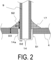
- FIG. 2 is an enlarged cross-sectional view illustrating an example of a section T of FIG. 1 .
- the manifold 4 and the fuel gas supply pipe 9 can be manufactured from a heat resistant metal such as alumina-forming stainless steel or a chromia-forming stainless steel.
- the insertion portion 14 is a through hole provided in the manifold 4, and although it is provided in the upper face of the manifold 4 in the embodiment illustrated in FIG. 2 , the insertion portion 14 may be provided in either face of the manifold 4.
- the thickness of the fuel gas supply pipe 9 and the manifold can each be from 0.5 mm to 3 mm.
- a gap 14a is provided between the insertion portion 14 of the manifold 4 and the fuel gas supply pipe 9.
- the fuel gas supply pipe 9 is allowed to move more easily inside the insertion portion 14, thereby enabling stress on a first joining portion 17 (hereinafter referred to as a "first joining portion") between the fuel gas supply pipe 9 and the manifold 4 to be alleviated.
- first joining portion a first joining portion 17
- the gap 14a may be provided over the entire circumference of the insertion portion 14 and the fuel gas supply pipe 9, or may be provided over a part of the circumference.
- the gap 14a can be from 0.05 mm to 1.0 mm.
- the cell stack device 1 of the present embodiment includes the first joining portion 17 that seals one end of the gap 14a as a result of joining the insertion portion 14 and the fuel gas supply pipe 9.
- the first joining portion has a meniscus shape, and a joint length D1 between the first joining portion 17 and the fuel gas supply pipe 9 in the insertion direction is longer than a thickness D2 of the fuel gas supply pipe 9.
- the toughness of the first joining portion 17 between the fuel gas supply pipe 9 and the manifold 4 can be maintained at a high level, and cracks in the first joining portion 17 can be inhibited.
- the long-term reliability of the cell stack device 1, a module 20, and a module housing device 40 can be improved.
- sealing one end of the gap means that the one end of the gap 14a on the inner side of the manifold 4 may be sealed, or the one end of the gap 14a on the outer side of the manifold 4 may be sealed.
- the first joining portion 17 is provided in the interior of the manifold 4.
- both the ends of the gap 14a may be sealed, and in this case, a surface of the first joining portion 17 exposed to a hydrogen-containing gas is referred to as a first surface S1, and a surface on the opposite side is referred to as a second surface S2.
- first joining portion means a region surrounded, in the arbitrarily defined cross-section along the insertion direction of the fuel gas supply pipe 9, by the first surface S 1, the second surface S2, a line connecting ends of the first surface S1 and the second surface S2 on the manifold 4 side and a line connecting ends of the first surface S1 and the second surface S2 on the fuel gas supply pipe 9 side.
- meniscus shape may be a concave meniscus shape as illustrated in FIGS. 2 and 3 , or may be a convex meniscus shape.
- the "thickness of the fuel gas supply pipe" D2 is a thickness of a part of the fuel gas supply pipe having the smallest thickness. However, the thickness of a part of the first joining portion 9 that is in contact with the first joining portion 17 is excluded.
- the second surface S2 may be formed as a part in which a structure of a crystal close to the surface is a dendritic structure, or may be formed as a part that has a different material composition from each of the manifold 4 and the fuel gas supply pipe 9.
- the joint length D1 may be shorter than double the thickness of the fuel gas supply pipe 9. In this way, the manifold 4 and the fuel gas supply pipe 9 is joined via the first joining portion 17 more strongly than necessary, and the freedom of movement of the first joining portion 17 is reduced; as a result, a concentration of the stress on the first joining portion 17 can be inhibited.
- the joint length D1 in the insertion direction may be longer than a thickness D3 of the manifold 4.
- the "thickness of the manifold" D3 is a thickness of a part having the smallest thickness of the wall of the manifold 4 in which the insertion portion 14 is provided, but the thickness of a part of the manifold 4 that is in contact with the first joining portion 17 is excluded.
- FIG. 3 is an enlarged cross-sectional view illustrating another example of the section T of FIG. 1 .
- a length D4 of the gap 14a in the insertion direction of the fuel gas supply pipe 9 is longer than the thickness D3 of the manifold 4.
- the embodiment illustrated in FIG. 3 can be realized by providing a first bent portion 14b, which extends toward the reformer 6 side along the fuel gas supply pipe 9, around a peripheral edge of the insertion portion 14 on the outer side of the manifold 4.
- a height H1 of the first bent portion 14b can be from 2 mm to 5 mm, for example.
- annular member which extends toward the reformer 6 side along the fuel gas supply pipe 9, may separately be provided around an outer periphery of the insertion portion 14.
- the bent portion or the annular member may be provided around the peripheral edge of the insertion portion on the inner side of the manifold.
- the first joining portion 17 is provided on a leading end of the first bent portion 14b, and the first bent portion 14b and the fuel gas supply pipe 9 are joined via the first joining portion 17. Meanwhile, as another embodiment, the first joining portion 17 may be provided on the first bent portion 14b on the manifold 4 side.
- FIG. 4 is a scanning electron microscope (SEM) photograph of a cross-section near the surface of the first joining portion 17. Note that, FIG. 4 illustrates a state of a result obtained by measuring crystal areas to be described below.
- an average crystal area of the first joining portion 17 can be 10000 ⁇ m 2 or less with respect to crystals present in a region (hereinafter referred to as an "analysis region") that is surrounded by a portion of an analysis surface A having a length of 500 ⁇ m in the first joining portion 17, two vertical lines B1 and B2 each having a length of 500 ⁇ m and having respective start points a1 and a2 at both ends of the analysis surface A, and a line C joining two end points c1 and c2 of the vertical lines.
- an analysis region that is surrounded by a portion of an analysis surface A having a length of 500 ⁇ m in the first joining portion 17, two vertical lines B1 and B2 each having a length of 500 ⁇ m and having respective start points a1 and a2 at both ends of the analysis surface A, and a line C joining two end points c1 and c2 of the vertical lines.
- the average crystal area may be 4000 ⁇ m 2 or less. Further, of the crystals in the analysis region of the first joining portion 17, the crystal area of all of the crystals (of each individual crystal), may be 40000 ⁇ m 2 or less. Note that "...crystals present in a region that is surrounded by” does not only refer to the crystals entirely included in the analysis region, but also refers to the crystals that are partially included in the analysis region.
- the average crystal area of the crystals positioned on the analysis surface A, of the first joining portion 17, having the length of 500 ⁇ m can be 5000 ⁇ m 2 or less. In this way, since the strength can be increased in the vicinity of the second surface in which cracks easily occur, the strength of the first joining portion 17 can be further increased.
- a method will be described for identifying the crystal area of the crystals in a cross-section of the first joining portion 17. Firstly, the scanning electron microscope is used to obtain a channeling contrast image in a cross section of the first joining portion 17 that includes the second surface. Next, the crystals appearing in the obtained channeling contrast image are identified. Lastly, of the identified crystals, the crystal areas of the crystals surrounded by the above-described analysis region are identified using an image analysis method or the like.
- the first joining portion 17 that joins the fuel gas supply pipe 9 and the manifold 4 can be provided by joining the manifold 4 and the fuel gas supply pipe 9 using a metallurgical joining method.
- the metallurgical joining methods are methods to perform joining through fusion welding, pressure welding, or soldering.
- Examples of the fusion welding include laser welding, plasma arc welding, inert gas arc welding, MAG welding, gas welding, or the like.
- Examples of the pressure welding include ultrasonic welding, friction welding, explosive welding, or the like.
- Adjustment of the joint length D1 between the first joining portion 17 and the fuel gas supply pipe 9, in the arbitrarily defined cross-section of the first joining portion 17 along the insertion direction of the fuel gas supply pipe 9, and adjustment of the crystal area of the crystals of the second surface of the first joining portion 17 can be realized by adjusting, as appropriate, various conditions of the joining method of the metallurgical joining methods.
- the adjustments can be realized by adjusting an irradiation angle and an irradiation output of a heat source.
- FIG. 5 is an enlarged cross-sectional view illustrating an example of the section T of FIG. 1 .
- an angle ⁇ 1 of the first joining portion 17 can be 30° or less. In this way, even if the fuel gas supply pipe 9 is deformed or moves, stress acting on the first joining portion 17, particularly stress acting on a first leading end portion 17b, can be alleviated, and the reliability of the joint between the fuel gas supply pipe 9 and the manifold 4 can be improved.
- the angle ⁇ 1 is an angle formed between a vertical line drawn from the first leading end portion 17b of the first joining portion 17 toward the manifold 4, and a first straight line L1 joining a first point 17c and the first leading end portion 17b, the first point 17c being in a first contour line S3 of the first joining portion 17 and positioned at a height that is half of a height from a first bottom portion 17a to the first leading end portion 17b of the first joining portion 17.
- the first joining portion 17 can be a concave meniscus shape, or a linear shape. In this way, it is possible to inhibit the stress acting on the first joining portion 17 from concentrating on a single point, and the stress acting on the first joining portion 17 can be alleviated.
- FIG. 6 is an external perspective view illustrating another example of the cell stack device of the present embodiment
- FIG. 7 is a plan view of the cell stack device illustrated in FIG. 6 with a part thereof not illustrated
- FIG. 8 is a cross-sectional view of the fuel gas supply pipe 9, the manifold 4, and a straightening plate 16 taken along a line X-X in FIG. 7 , and other members are illustrated in a side view.
- the manifold 4 of a cell stack device 111 illustrated in FIG. 6 to FIG. 8 includes a main body portion 4a including a space that is communicated with the gas flow passages, and a flange portion 4b that protrudes from the main body portion 4a.
- the gas is supplied to the fuel cells 3 via the space in the main body portion 4a.
- the other end of the fuel gas supply pipe 9 is joined to the manifold 4 by being inserted from the side of a first face n1 into a first through hole 14d, which is the insertion portion 14, configured to penetrate through the flange portion 4b.
- the other end of the fuel gas supply pipe 9 is joined to the manifold 4 by being inserted from the side of a second face n2 into the second through hole 14e, which is the insertion portion 14, configured to penetrate through the main body portion 4a.
- the manifold 4 includes the straightening plate 16 that is separated from the other end of the fuel gas supply pipe 9 and covers the other end.
- the straightening plate 16 is provided perpendicularly to a flow-out direction of gas flowing out from the second through hole 14e.
- the straightening plate 16 includes an opening portion. The opening portion may be provided such that the gas flows toward the fuel cell 3 at the end of the cell stack 5 that is separated from the straightening plate 16.
- the surface on the side on which the cell stack 5 is joined and mounted is the first face n1
- the surface on the opposite side to the first face n1 is the second face n2.
- FIG. 9 is an enlarged cross-sectional view illustrating an example of a section B of FIG. 8 .
- the other end of the fuel gas supply pipe 9 and the manifold 4 are joined via a second joining portion 18.
- an angle ⁇ 2 of the second joining portion 18 can be 30° or less. In this way, even if the fuel gas supply pipe 9 is deformed or moves, stress acting on the second joining portion 18, particularly stress acting on a second leading end portion 18b, can be alleviated, and the reliability of the joint between the fuel gas supply pipe 9 and the manifold 4 can be improved.
- the angle ⁇ 2 is an angle formed between a vertical line drawn from the second leading end portion 18b of the second joining portion 18 toward the manifold 4, and a second straight line L2 joining a second point 18c and the second leading end portion 18b, the second point 18c being in a second contour line S4 of the second joining portion 18 and positioned at a height that is half of a height from a second bottom portion 18a to the second leading end portion 18b of the second joining portion 18.
- the second joining portion 18 can be the concave meniscus shape, or the linear shape. In this way, it is possible to inhibit the stress acting on the second joining portion 18 from concentrating on a single point, and the stress acting on the second joining portion 18 can be alleviated.
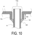
- FIG. 10 is an enlarged cross-sectional view illustrating another example of the section B of FIG. 8 .
- a second bent portion 14c is provided which extends toward the reformer 6 along the fuel gas supply pipe 9, around an outer periphery of the second through hole 14e in the manifold 4, and an upper end portion of the second bent portion 14c and the fuel gas supply pipe 9 are joined via the second joining portion 18.
- a height H2 of the second bent portion 14c can be from 2 mm to 5 mm, for example.
- the first through hole 14d is formed by penetrating the flange portion 4b through a processing method, such as a punching process.
- the second through hole 14e is formed by penetrating the main body portion 4a through a processing method, such as the punching process.
- the first joining portion 17 and the second joining portion 18 to which the fuel gas supply pipe 9 and the manifold 4 are joined can be provided by joining an outer surface of the manifold 4 and the fuel gas supply pipe 9 using a metallurgical joining method.
- the metallurgical joining methods are the methods to perform joining through the fusion welding, the pressure welding, or the soldering.
- the fusion welding include the laser welding, the plasma arc welding, the inert gas arc welding, the MAG welding, the gas welding, or the like.
- examples of the pressure welding include the ultrasonic welding, the friction welding, the explosive welding, or the like.
- the first bent portion 14b and the second bent portion 14c can be manufactured by a processing method such as the pressing process using dies having the shapes of the first bent portion 14b and the second bent portion 14c.
- first bent portion 14b and the second bent portion 14c are provided separately from the outer peripheries of the first through hole 14d and the second through hole 14e, respectively.
- members having the shapes of the first bent portion 14b and the second bent portion 14c may be prepared, and the respective members may be joined to the outer peripheries of the first through hole 14d and the second through hole 14e using the above-described metallurgical joining method.
- the fuel electrode layer can be formed of a porous electrically conductive ceramic, such as ZrO 2 solid solution with a rare earth element oxide (referred to as a stabilized zirconia that also includes partially stabilized zirconia), and at least one of Ni and NiO.
- a porous electrically conductive ceramic such as ZrO 2 solid solution with a rare earth element oxide (referred to as a stabilized zirconia that also includes partially stabilized zirconia), and at least one of Ni and NiO.
- the solid electrolyte layer functions as an electrolyte that allows electron transfer between the electrodes, and has a gas blocking property that prevents leaks of the fuel gas and the oxygen-containing gas.
- the solid electrolyte layer is formed of ZrO 2 solid solution containing 3 to 15 mol% of the rare earth element oxide. Note that the solid electrolyte layer may be formed from another material as long as that material exhibits the above-described properties.
- the material for an oxygen electrode layer is not particularly limited, and any well-known general material may be used.
- the oxygen electrode layer can be formed of an electrically conductive ceramic made from a so-called ABO 3 perovskite oxide.
- the oxygen electrode layer is gas permeable, and the open porosity thereof is in a range of 20% or more, and particularly in a range from 30 to 50%.
- the interconnector can be formed from an electrically conductive ceramic, but since the interconnector comes contact with the fuel gas (the hydrogen-containing gas) and the oxygen-containing gas (air or the like), a lanthanum chromite perovskite oxide (LaCrO 3 based oxide) that is reduction resistant and oxidation resistant can be used.
- the interconnector is dense and has a relative density of 93% or greater, and particularly 95% or greater.
- the support body is gas permeable to allow the fuel gas to permeate therethrough and arrive at the fuel electrode layer, and further, is electrically conductive to allow current collection via the interconnector.
- a material that satisfies these requirements such as an electrically conductive ceramic or cermet can be used as the support body.
- the column-shaped support body is an elongated plate that extends in the erecting direction of the fuel cells 3, and has a shape of a hollow flat plate that includes a pair of opposing flat surfaces and two semicircular side surfaces. Then, lower end portions of the fuel cells 3 and a lower end portion of the above-described electrically conductive member are fixed to the manifold 4 that supplies the fuel gas to the fuel cells 3, by the insulating adhesive, such as the glass sealing material, and the gas flow passages provided in the support body communicate with a fuel gas chamber inside the manifold 4.
- the insulating adhesive such as the glass sealing material
- the support body can be made from an iron group metal, such as Ni, and a specific rare earth oxide, such as Y 2 O 3 .
- the support body has an open porosity of 20% or more, and particularly in a range from 25 to 50%.
- the support body also has an electrical conductivity of 300 S/cm or more, and particularly 440 S/cm or more.
- a portion in which the fuel electrode layer and the oxygen electrode layer face each other via the solid electrolyte layer functions as a power generating element. That is, the oxygen-containing gas, such as air, flows outside the oxygen electrode layer and the fuel gas (the hydrogen-containing gas) flows in the gas flow passages inside the support body, and the gases are heated to a predetermined actuation temperature, generating power as a result. Then, current generated by this power generation is collected by the above-described electrically conductive member, via the interconnector disposed on the support body.
- FIG. 11 is an external perspective view illustrating, in an exploded manner, the module 20 configured by the cell stack illustrated in FIG. 1 being contained inside a housing container.
- the module 20 is configured by the cell stack device 1 illustrated in FIG. 1 being contained inside a rectangular cuboid-shaped housing container 21.
- FIG. 11 illustrates a state in which parts (front and back faces) of the housing container 21 are detached and the cell stack device 1 and the reformer 6 contained inside have been removed to the rear.
- the cell stack device 1 can be contained in the housing container 21 by being slid thereinto.
- the module 20 of the present embodiment since the above-described cell stack device 1 is contained in the housing container 21, the module 20 with improved durability can be obtained.
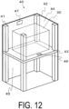
- FIG. 12 is a perspective view illustrating an example of a fuel cell device that is the module housing device 40 in which the module 20 illustrated in FIG. 11 and an auxiliary device configured to operate the cell stack device 1 are contained inside an external casing. Note that a part of the configuration is omitted in FIG. 12 .
- the external casing configured by supports 41 and exterior plates 42 is divided into an upper side and a lower side by a dividing plate 43.
- the upper side forms a module housing chamber 44 that contains the above-described module 20, and the lower side forms an auxiliary device housing chamber 45 that contains the auxiliary device configured to operate the module 20. Note that the auxiliary device contained in the auxiliary device housing chamber 45 is not illustrated.
- an airflow hole 46 is formed in the dividing plate 43.
- the air flow hole 46 allows air in the auxiliary device housing chamber 45 to flow into the module housing chamber 44.
- An exhaust hole 47 is formed in a part of the outer plates 42 that configure the module housing chamber 44. Air inside the module housing chamber 44 is discharged through the exhaust hole 47.
- the module housing device 40 As described above, by configuring the module 20 having improved durability to be contained in the module housing chamber 44, it is possible to obtain the module housing device 40 having improved durability.
- the fuel cells 3, the cell stack device 1, the module 20, and the module housing device 40 are described in the above-described embodiment.
- the present disclosure can also be applied to electrolytic cells (SOEC) that generate hydrogen and oxygen (O 2 ) as a result of electrolyzing water vapor (water) by applying water vapor and voltage to a cell, an electrolytic cell stack device and an electrolytic module that are provided with the electrolytic cells, and an electrolytic device that is a module housing device.
- SOEC electrolytic cells
- O 2 hydrogen and oxygen
- the manifold and the fuel gas supply pipe were welded using the laser welding method, and samples shown in Tables 1 to 4 were manufactured.
- the various members of the cell stack device were the same as those illustrated in FIG. 1 .
- the cell stack device included the reformer.
- the thickness of the fuel gas supply pipe was 0.9 mm. Then, the samples having different joint lengths between the first joining portion and the fuel gas supply pipe, or different crystal areas of the crystals in the vicinity of the second surface of the first joining portion were manufactured.
- Hydrogen-containing gas was caused to flow through the gas flow passages of the fuel cells of the cell stack device, and further, air was caused to flow on the outer side of the fuel cells (on the outer face of the air electrode layer). Then, power was generated for 24 hours at 850°C. After that, the hydrogen-containing gas was stopped and the cell stack device was naturally cooled. The above procedure was repeatedly performed up to a predetermined number of repetitions, the test was stopped, and the presence or absence of cracks was verified. The results are shown in Tables 1 to 4.
- Tables 1 to 4 The test results are shown in Tables 1 to 4. Note that, in Tables 1 to 4, the joint length between the first joining portion and the fuel gas supply pipe, an average crystal area value, a maximum crystal area value, a value of the average crystal area of the crystals positioned on the surface of the first joining portion, and a number of cycles of a thermal cycling test are listed. [Table 1] Sample No.
Landscapes
- Chemical & Material Sciences (AREA)
- Engineering & Computer Science (AREA)
- Electrochemistry (AREA)
- Chemical Kinetics & Catalysis (AREA)
- Sustainable Development (AREA)
- Sustainable Energy (AREA)
- Life Sciences & Earth Sciences (AREA)
- Manufacturing & Machinery (AREA)
- General Chemical & Material Sciences (AREA)
- Materials Engineering (AREA)
- Metallurgy (AREA)
- Organic Chemistry (AREA)
- Fuel Cell (AREA)
- Inorganic Chemistry (AREA)
- Electrolytic Production Of Non-Metals, Compounds, Apparatuses Therefor (AREA)
Claims (14)
- Zellenstapelvorrichtung, aufweisend:einen Zellenstapel, der durch eine Mehrzahl von Zellen konfiguriert ist, wobei jede aus der Mehrzahl von Zellen eine Säulenform hat und im Inneren einen Gasströmungsdurchgang aufweist, wobei die Mehrzahl von Zellen vertikal angeordnet und elektrisch verbunden ist,einen Verteiler, der konfiguriert ist, um untere Enden der Mehrzahl von Zellen zu fixieren und ein Reaktionsgas in die Gasströmungsdurchgänge der Mehrzahl von Zellen zuzuführen, undein Reaktionsgaszuführrohr, das mit dem Verteiler verbunden und konfiguriert ist, um das Reaktionsgas dem Verteiler zuzuführen, wobeider Verteiler und das Reaktionsgaszuführrohr aus Metall hergestellt sind,der Verteiler aufweist:einen Einsetzabschnitt, der konfiguriert ist, um das Reaktionsgaszuführrohr mit dem Verteiler zu verbinden,einen Spalt zwischen dem Einsetzabschnitt und dem Reaktionsgaszuführrohr, undeinen ersten Verbindungsabschnitt, der konfiguriert ist, um den Einsetzabschnitt und das Reaktionsgaszuführrohr zu verbinden und ein Ende des Spalts an der Außenseite des Verteilers abzudichten,wobei der erste Verbindungsabschnitt in einem beliebig definierten Querschnitt entlang einer Einsetzrichtung des Reaktionsgaszuführrohrs eine Meniskusform hat,eine Verbindungslänge in der Einsetzrichtung zwischen dem ersten Verbindungsabschnitt und dem Reaktionsgaszuführrohr länger als eine Dicke des Reaktionsgaszuführrohrs ist, undeine Länge des Spalts in der Einsetzrichtung länger als die Dicke des Verteilers ist.
- Zellenstapelvorrichtung gemäß Anspruch 1, wobei die Verbindungslänge kürzer als die doppelte Dicke des Reaktionsgaszuführrohrs ist.
- Zellenstapelvorrichtung gemäß Anspruch 1 oder 2, wobei
in dem beliebig definierten Querschnitt entlang der Einsetzrichtung des Reaktionsgaszuführrohrs die Verbindungslänge in der Einsetzrichtung länger als die Dicke des Verteilers ist. - Zellenstapelvorrichtung gemäß irgendeinem der Ansprüche 1 bis 3, wobei
in dem beliebig definierten Querschnitt entlang der Einsetzrichtung eine durchschnittliche Kristallfläche 10000 µm2 oder weniger beträgt, bezogen auf Kristalle, die in einem Bereich vorliegen, der umgeben ist von einem Abschnitt einer Fläche des ersten Verbindungsabschnitts mit einer Länge von 500 pm, wobei zwei vertikale Linien jeweils eine Länge von 500 µm haben und mit jeweiligen Startpunkten an beiden Enden der Fläche, und einer Linie, die zwei Endpunkte der vertikalen Linien verbindet. - Zellenstapelvorrichtung gemäß Anspruch 4, wobei
die durchschnittliche Kristallfläche 4000 µm2 oder weniger beträgt, bezogen auf die Kristalle, die im Bereich des ersten Verbindungsabschnitts vorliegen. - Zellenstapelvorrichtung gemäß Anspruch 4 oder 5,
wobei
eine Kristallfläche aller Kristalle, die in dem Bereich des ersten Verbindungsabschnitts vorliegen, 40000 µm2 oder weniger beträgt. - Zellenstapelvorrichtung gemäß irgendeinem der Ansprüche 4 bis 6, wobei
in dem Bereich des ersten Verbindungsabschnitts eine durchschnittliche Kristallfläche von Kristallen, die auf der Fläche des ersten Verbindungsabschnitts angeordnet sind, 2000 µm2 oder weniger beträgt. - Zellenstapelvorrichtung gemäß irgendeinem der Ansprüche 1 bis 7, wobeidas Reaktionsgaszuführrohr an einem Ende des Reaktionsgaszuführrohrs mit einer Reaktionsgaszuführquelle verbunden ist, wobei das andere Ende des Reaktionsgaszuführrohrs in ein erstes Durchgangsloch, das in dem Verteiler vorgesehen ist, eingesetzt und über den ersten Verbindungsabschnitt mit dem Verteiler verbunden ist, undin dem beliebig definierten Querschnitt entlang der Einsetzrichtung des Reaktionsgaszuführrohrs ein Winkel θ1 30° oder weniger beträgt, wobei der Winkel θ1 zwischen einer vertikalen Linie, die von einem ersten vorderen Endabschnitt des ersten Verbindungsabschnitts zu dem Verteiler gezogen wird, und einer ersten geraden Linie gebildet wird, die den ersten vorderen Endabschnitt mit einem ersten Punkt verbindet, der in einer ersten Konturlinie des ersten Verbindungsabschnitts liegt und auf halber Höhe von einem ersten Bodenabschnitt zu dem ersten vorderen Endabschnitt des ersten Verbindungsabschnitts positioniert ist.
- Zellenstapelvorrichtung gemäß irgendeinem der Ansprüche 1 bis 8, wobei
der erste Verbindungsabschnitt eines von einer konkaven Meniskusform und einer linearen Form hat. - Zellenstapelvorrichtung gemäß irgendeinem der Ansprüche 1 bis 9, wobeiein erster Biegeabschnitt, der sich in Richtung zu einer Seite der Reaktionsgaszuführquelle entlang des Reaktionsgaszuführrohrs erstreckt, um einen Außenumfang des ersten Durchgangslochs in dem Verteiler vorgesehen ist, undein oberer Endabschnitt des ersten Biegeabschnitts und das Reaktionsgaszuführrohr über den ersten Verbindungsabschnitt verbunden sind.
- Zellenstapelvorrichtung gemäß irgendeinem der Ansprüche 1 bis 10, wobeider Verteiler aufweist:einen Hauptkörperabschnitt, aufweisend einen Raum, der mit den Gasströmungsdurchgängen kommuniziert, undeinen Flanschabschnitt, der von dem Hauptkörperabschnitt aus hervorsteht,wobei der Flanschabschnitt das erste Durchgangsloch aufweist und der Hauptkörperabschnitt ein zweites Durchgangsloch aufweist,das andere Ende des Reaktionsgaszuführrohrs in das zweite Durchgangsloch eingesetzt ist und das andere Ende und der Verteiler über einen zweiten Verbindungsabschnitt verbunden sind, undin dem beliebig definierten Querschnitt entlang der Einsetzrichtung des Reaktionsgaszuführrohrs ein Winkel θ2 30° oder weniger beträgt, wobei der Winkel θ2 zwischen einer vertikalen Linie, die von einem zweiten vorderen Endabschnitt des zweiten Verbindungsabschnitts zu dem Verteiler gezogen wird, und einer zweiten geraden Linie gebildet wird, die den zweiten vorderen Endabschnitt mit einem zweiten Punkt verbindet, der in einer zweiten Konturlinie des zweiten Verbindungsabschnitts liegt und auf halber Höhe von einem zweiten Bodenabschnitt zu dem zweiten vorderen Endabschnitt des zweiten Verbindungsabschnitts positioniert ist,wobei optional der zweite Verbindungsabschnitt eines von einer konkaven Meniskusform und einer linearen Form hat.
- Zellenstapelvorrichtung gemäß Anspruch 10 oder 11, wobeiein zweiter Biegeabschnitt, der sich in Richtung zu der Seite der Reaktionsgaszuführquelle entlang des Reaktionsgaszuführrohrs erstreckt, um einen Außenumfang des zweiten Durchgangslochs in dem Verteiler vorgesehen ist, undein oberer Endabschnitt des zweiten Biegeabschnitts und das Reaktionsgaszuführrohr miteinander verbunden sind.
- Modul, aufweisend:
die Zellenstapelvorrichtung gemäß irgendeinem der Ansprüche 1 bis 12, die in einem Gehäusebehälter enthalten ist. - Modulgehäusevorrichtung, aufweisend:das Modul gemäß Anspruch 13,eine Hilfsvorrichtung, die zum Betätigen des Moduls konfiguriert ist, undein Außengehäuse, das konfiguriert ist, um das Modul und die Hilfsvorrichtung darin zu enthalten.
Applications Claiming Priority (3)
| Application Number | Priority Date | Filing Date | Title |
|---|---|---|---|
| JP2016210735 | 2016-10-27 | ||
| JP2017057653 | 2017-03-23 | ||
| PCT/JP2017/038732 WO2018079665A1 (ja) | 2016-10-27 | 2017-10-26 | セルスタック装置、モジュールおよびモジュール収納装置 |
Publications (3)
| Publication Number | Publication Date |
|---|---|
| EP3534449A1 EP3534449A1 (de) | 2019-09-04 |
| EP3534449A4 EP3534449A4 (de) | 2020-05-27 |
| EP3534449B1 true EP3534449B1 (de) | 2023-05-10 |
Family
ID=62023662
Family Applications (1)
| Application Number | Title | Priority Date | Filing Date |
|---|---|---|---|
| EP17866128.6A Active EP3534449B1 (de) | 2016-10-27 | 2017-10-26 | Zellenstapelvorrichtung, modul und modulspeichervorrichtung |
Country Status (5)
| Country | Link |
|---|---|
| US (2) | US11309573B2 (de) |
| EP (1) | EP3534449B1 (de) |
| JP (1) | JP6818763B2 (de) |
| CN (1) | CN109845013B (de) |
| WO (1) | WO2018079665A1 (de) |
Families Citing this family (7)
| Publication number | Priority date | Publication date | Assignee | Title |
|---|---|---|---|---|
| JP6527917B2 (ja) * | 2017-07-07 | 2019-06-12 | 日本碍子株式会社 | セルスタック装置 |
| CN112602220A (zh) * | 2018-09-07 | 2021-04-02 | 日本碍子株式会社 | 分流器、电池堆装置以及电化学单电池 |
| KR102140468B1 (ko) * | 2018-12-26 | 2020-08-03 | 한국과학기술연구원 | 스택 내부의 열분포가 개선된 연료전지 |
| JP7360276B2 (ja) | 2019-08-30 | 2023-10-12 | 太陽誘電株式会社 | 固体酸化物型燃料電池およびその製造方法 |
| JP7377051B2 (ja) | 2019-10-07 | 2023-11-09 | 太陽誘電株式会社 | 固体酸化物型燃料電池およびその製造方法 |
| JP7429568B2 (ja) * | 2020-03-10 | 2024-02-08 | 太陽誘電株式会社 | 固体酸化物型燃料電池およびその製造方法 |
| JP7484048B2 (ja) | 2020-03-10 | 2024-05-16 | 太陽誘電株式会社 | 固体酸化物型燃料電池およびその製造方法 |
Family Cites Families (21)
| Publication number | Priority date | Publication date | Assignee | Title |
|---|---|---|---|---|
| JP2002336990A (ja) * | 2001-05-11 | 2002-11-26 | Daido Steel Co Ltd | 高温引張り強さ、伸び、耐割れ性および靭性の優れたフェライト系ステンレス鋼の溶接部および溶接方法 |
| JP2005000971A (ja) * | 2003-06-13 | 2005-01-06 | Daido Steel Co Ltd | 衝撃特性にすぐれた溶接部を与えるフェライト系ステンレス鋼溶接ワイヤおよび溶接方法 |
| JP4587659B2 (ja) * | 2003-11-26 | 2010-11-24 | 京セラ株式会社 | 燃料電池セルスタックの製法 |
| US8026011B2 (en) * | 2004-01-28 | 2011-09-27 | Kyocera Corporation | Fuel cell assembly |
| JP5033324B2 (ja) * | 2005-11-30 | 2012-09-26 | 京セラ株式会社 | 燃料電池スタック及び燃料電池 |
| JP4969880B2 (ja) * | 2005-11-30 | 2012-07-04 | 京セラ株式会社 | 燃料電池 |
| US20080138665A1 (en) * | 2006-12-06 | 2008-06-12 | 3M Innovative Properties Company | Compact fuel cell stack with gas ports |
| US9246184B1 (en) * | 2007-11-13 | 2016-01-26 | Bloom Energy Corporation | Electrolyte supported cell designed for longer life and higher power |
| WO2009119615A1 (ja) * | 2008-03-26 | 2009-10-01 | 京セラ株式会社 | 燃料電池モジュールおよび燃料電池装置 |
| JP5116185B1 (ja) * | 2011-10-14 | 2013-01-09 | 日本碍子株式会社 | 接合材、及び、その接合材を用いた燃料電池のスタック構造体 |
| EP2787570B1 (de) * | 2011-11-28 | 2017-04-19 | Kyocera Corporation | Verfahren zur herstellung einer brennstoffzellenstapelvorrichtung |
| JP2014143162A (ja) | 2012-12-26 | 2014-08-07 | Kyocera Corp | セルスタック装置および燃料電池装置 |
| CN103996868B (zh) * | 2013-02-18 | 2016-06-15 | 本田技研工业株式会社 | 燃料电池堆 |
| CN103143799B (zh) * | 2013-03-12 | 2015-07-08 | 嵊州市致远焊接制品有限公司 | 一种连接管件的加工工艺 |
| US20140295303A1 (en) * | 2013-03-28 | 2014-10-02 | Toto Ltd. | Solid oxide fuel cell |
| DE102013209970B3 (de) * | 2013-05-28 | 2014-07-24 | Schott Ag | Glasiges oder zumindest teilkristallines Fügematerial und dessen Verwendung sowie Fügeverbindung |
| EP2822075A1 (de) * | 2013-07-03 | 2015-01-07 | Toto Ltd. | Festoxid-Brennstoffzelleneinheit |
| JP6162542B2 (ja) * | 2013-08-22 | 2017-07-12 | 日本特殊陶業株式会社 | 燃料電池 |
| CN106233519B (zh) * | 2014-04-21 | 2019-04-05 | 京瓷株式会社 | 电池堆装置、模块以及模块收容装置 |
| JP6198674B2 (ja) * | 2014-05-19 | 2017-09-20 | 本田技研工業株式会社 | 燃料電池スタック |
| JP5873949B1 (ja) * | 2014-10-21 | 2016-03-01 | 日本碍子株式会社 | 燃料マニホールド |
-
2017
- 2017-10-26 WO PCT/JP2017/038732 patent/WO2018079665A1/ja not_active Ceased
- 2017-10-26 CN CN201780063888.5A patent/CN109845013B/zh active Active
- 2017-10-26 US US16/345,280 patent/US11309573B2/en active Active
- 2017-10-26 EP EP17866128.6A patent/EP3534449B1/de active Active
- 2017-10-26 JP JP2018547758A patent/JP6818763B2/ja active Active
-
2022
- 2022-03-14 US US17/693,464 patent/US11742510B2/en active Active
Also Published As
| Publication number | Publication date |
|---|---|
| JP6818763B2 (ja) | 2021-01-20 |
| US11742510B2 (en) | 2023-08-29 |
| US11309573B2 (en) | 2022-04-19 |
| EP3534449A4 (de) | 2020-05-27 |
| WO2018079665A1 (ja) | 2018-05-03 |
| US20220200036A1 (en) | 2022-06-23 |
| US20190296385A1 (en) | 2019-09-26 |
| JPWO2018079665A1 (ja) | 2019-06-24 |
| CN109845013B (zh) | 2022-05-24 |
| EP3534449A1 (de) | 2019-09-04 |
| CN109845013A (zh) | 2019-06-04 |
Similar Documents
| Publication | Publication Date | Title |
|---|---|---|
| US11742510B2 (en) | Cell stack device, module, and module housing device | |
| US10497949B2 (en) | Electro-chemical reaction unit and fuel cell stack | |
| JP2020009744A (ja) | 電気化学反応単位および電気化学反応セルスタック | |
| US10763516B2 (en) | Interconnector-electrochemical reaction single cell composite body, and electrochemical reaction cell stack | |
| US9876250B2 (en) | Cell stack device, module, and module housing device | |
| US11394039B2 (en) | Electro-chemical reaction unit having glass seal member composed of vertically long crystal grains, and electro-chemical reaction cell stack, and electro-chemical reaction unit production method comprising same | |
| US10476087B2 (en) | Fuel-cell power generation unit and fuel-cell stack | |
| JP6667278B2 (ja) | 電気化学反応セルスタック | |
| US11271221B2 (en) | Electrochemical reaction cell stack, interconnector-electrochemical reaction unit cell composite, and method for manufacturing electrochemical reaction cell stack | |
| JP2019003795A (ja) | 電気化学反応単位および電気化学反応セルスタック | |
| JP2022073494A (ja) | 電気化学反応セルスタック | |
| KR101934082B1 (ko) | 통합된 가스 분포 튜브가 장착된 얇은 엔드플레이트를 갖는 연료 전지 스택 | |
| JP7169333B2 (ja) | 電気化学反応セルスタック | |
| US11027982B2 (en) | Mica-made member, electrochemical reaction unit, and electrochemical reaction cell stack |
Legal Events
| Date | Code | Title | Description |
|---|---|---|---|
| STAA | Information on the status of an ep patent application or granted ep patent |
Free format text: STATUS: THE INTERNATIONAL PUBLICATION HAS BEEN MADE |
|
| PUAI | Public reference made under article 153(3) epc to a published international application that has entered the european phase |
Free format text: ORIGINAL CODE: 0009012 |
|
| STAA | Information on the status of an ep patent application or granted ep patent |
Free format text: STATUS: REQUEST FOR EXAMINATION WAS MADE |
|
| 17P | Request for examination filed |
Effective date: 20190425 |
|
| AK | Designated contracting states |
Kind code of ref document: A1 Designated state(s): AL AT BE BG CH CY CZ DE DK EE ES FI FR GB GR HR HU IE IS IT LI LT LU LV MC MK MT NL NO PL PT RO RS SE SI SK SM TR |
|
| AX | Request for extension of the european patent |
Extension state: BA ME |
|
| DAV | Request for validation of the european patent (deleted) | ||
| DAX | Request for extension of the european patent (deleted) | ||
| A4 | Supplementary search report drawn up and despatched |
Effective date: 20200429 |
|
| RIC1 | Information provided on ipc code assigned before grant |
Ipc: H01M 8/0282 20160101ALN20200422BHEP Ipc: C25B 1/10 20060101ALI20200422BHEP Ipc: H01M 8/12 20160101ALI20200422BHEP Ipc: H01M 8/0276 20160101ALI20200422BHEP Ipc: H01M 8/2485 20160101AFI20200422BHEP Ipc: H01M 8/243 20160101ALI20200422BHEP Ipc: H01M 8/124 20160101ALN20200422BHEP |
|
| GRAP | Despatch of communication of intention to grant a patent |
Free format text: ORIGINAL CODE: EPIDOSNIGR1 |
|
| STAA | Information on the status of an ep patent application or granted ep patent |
Free format text: STATUS: GRANT OF PATENT IS INTENDED |
|
| RIC1 | Information provided on ipc code assigned before grant |
Ipc: H01M 8/124 20160101ALN20221129BHEP Ipc: H01M 8/0282 20160101ALN20221129BHEP Ipc: C25B 9/73 20210101ALI20221129BHEP Ipc: C25B 1/04 20060101ALI20221129BHEP Ipc: H01M 8/243 20160101ALI20221129BHEP Ipc: H01M 8/0276 20160101ALI20221129BHEP Ipc: H01M 8/12 20160101ALI20221129BHEP Ipc: H01M 8/2485 20160101AFI20221129BHEP |
|
| INTG | Intention to grant announced |
Effective date: 20221220 |
|
| GRAS | Grant fee paid |
Free format text: ORIGINAL CODE: EPIDOSNIGR3 |
|
| GRAA | (expected) grant |
Free format text: ORIGINAL CODE: 0009210 |
|
| STAA | Information on the status of an ep patent application or granted ep patent |
Free format text: STATUS: THE PATENT HAS BEEN GRANTED |
|
| AK | Designated contracting states |
Kind code of ref document: B1 Designated state(s): AL AT BE BG CH CY CZ DE DK EE ES FI FR GB GR HR HU IE IS IT LI LT LU LV MC MK MT NL NO PL PT RO RS SE SI SK SM TR |
|
| REG | Reference to a national code |
Ref country code: GB Ref legal event code: FG4D |
|
| REG | Reference to a national code |
Ref country code: AT Ref legal event code: REF Ref document number: 1567622 Country of ref document: AT Kind code of ref document: T Effective date: 20230515 Ref country code: CH Ref legal event code: EP |
|
| REG | Reference to a national code |
Ref country code: DE Ref legal event code: R096 Ref document number: 602017068730 Country of ref document: DE |
|
| REG | Reference to a national code |
Ref country code: IE Ref legal event code: FG4D |
|
| P01 | Opt-out of the competence of the unified patent court (upc) registered |
Effective date: 20230505 |
|
| REG | Reference to a national code |
Ref country code: LT Ref legal event code: MG9D |
|
| REG | Reference to a national code |
Ref country code: NL Ref legal event code: MP Effective date: 20230510 |
|
| REG | Reference to a national code |
Ref country code: AT Ref legal event code: MK05 Ref document number: 1567622 Country of ref document: AT Kind code of ref document: T Effective date: 20230510 |
|
| PG25 | Lapsed in a contracting state [announced via postgrant information from national office to epo] |
Ref country code: SE Free format text: LAPSE BECAUSE OF FAILURE TO SUBMIT A TRANSLATION OF THE DESCRIPTION OR TO PAY THE FEE WITHIN THE PRESCRIBED TIME-LIMIT Effective date: 20230510 Ref country code: PT Free format text: LAPSE BECAUSE OF FAILURE TO SUBMIT A TRANSLATION OF THE DESCRIPTION OR TO PAY THE FEE WITHIN THE PRESCRIBED TIME-LIMIT Effective date: 20230911 Ref country code: NO Free format text: LAPSE BECAUSE OF FAILURE TO SUBMIT A TRANSLATION OF THE DESCRIPTION OR TO PAY THE FEE WITHIN THE PRESCRIBED TIME-LIMIT Effective date: 20230810 Ref country code: NL Free format text: LAPSE BECAUSE OF FAILURE TO SUBMIT A TRANSLATION OF THE DESCRIPTION OR TO PAY THE FEE WITHIN THE PRESCRIBED TIME-LIMIT Effective date: 20230510 Ref country code: ES Free format text: LAPSE BECAUSE OF FAILURE TO SUBMIT A TRANSLATION OF THE DESCRIPTION OR TO PAY THE FEE WITHIN THE PRESCRIBED TIME-LIMIT Effective date: 20230510 Ref country code: AT Free format text: LAPSE BECAUSE OF FAILURE TO SUBMIT A TRANSLATION OF THE DESCRIPTION OR TO PAY THE FEE WITHIN THE PRESCRIBED TIME-LIMIT Effective date: 20230510 |
|
| PG25 | Lapsed in a contracting state [announced via postgrant information from national office to epo] |
Ref country code: RS Free format text: LAPSE BECAUSE OF FAILURE TO SUBMIT A TRANSLATION OF THE DESCRIPTION OR TO PAY THE FEE WITHIN THE PRESCRIBED TIME-LIMIT Effective date: 20230510 Ref country code: PL Free format text: LAPSE BECAUSE OF FAILURE TO SUBMIT A TRANSLATION OF THE DESCRIPTION OR TO PAY THE FEE WITHIN THE PRESCRIBED TIME-LIMIT Effective date: 20230510 Ref country code: LV Free format text: LAPSE BECAUSE OF FAILURE TO SUBMIT A TRANSLATION OF THE DESCRIPTION OR TO PAY THE FEE WITHIN THE PRESCRIBED TIME-LIMIT Effective date: 20230510 Ref country code: LT Free format text: LAPSE BECAUSE OF FAILURE TO SUBMIT A TRANSLATION OF THE DESCRIPTION OR TO PAY THE FEE WITHIN THE PRESCRIBED TIME-LIMIT Effective date: 20230510 Ref country code: IS Free format text: LAPSE BECAUSE OF FAILURE TO SUBMIT A TRANSLATION OF THE DESCRIPTION OR TO PAY THE FEE WITHIN THE PRESCRIBED TIME-LIMIT Effective date: 20230910 Ref country code: HR Free format text: LAPSE BECAUSE OF FAILURE TO SUBMIT A TRANSLATION OF THE DESCRIPTION OR TO PAY THE FEE WITHIN THE PRESCRIBED TIME-LIMIT Effective date: 20230510 Ref country code: GR Free format text: LAPSE BECAUSE OF FAILURE TO SUBMIT A TRANSLATION OF THE DESCRIPTION OR TO PAY THE FEE WITHIN THE PRESCRIBED TIME-LIMIT Effective date: 20230811 |
|
| PG25 | Lapsed in a contracting state [announced via postgrant information from national office to epo] |
Ref country code: SK Free format text: LAPSE BECAUSE OF FAILURE TO SUBMIT A TRANSLATION OF THE DESCRIPTION OR TO PAY THE FEE WITHIN THE PRESCRIBED TIME-LIMIT Effective date: 20230510 |
|
| PG25 | Lapsed in a contracting state [announced via postgrant information from national office to epo] |
Ref country code: SM Free format text: LAPSE BECAUSE OF FAILURE TO SUBMIT A TRANSLATION OF THE DESCRIPTION OR TO PAY THE FEE WITHIN THE PRESCRIBED TIME-LIMIT Effective date: 20230510 Ref country code: SK Free format text: LAPSE BECAUSE OF FAILURE TO SUBMIT A TRANSLATION OF THE DESCRIPTION OR TO PAY THE FEE WITHIN THE PRESCRIBED TIME-LIMIT Effective date: 20230510 Ref country code: RO Free format text: LAPSE BECAUSE OF FAILURE TO SUBMIT A TRANSLATION OF THE DESCRIPTION OR TO PAY THE FEE WITHIN THE PRESCRIBED TIME-LIMIT Effective date: 20230510 Ref country code: EE Free format text: LAPSE BECAUSE OF FAILURE TO SUBMIT A TRANSLATION OF THE DESCRIPTION OR TO PAY THE FEE WITHIN THE PRESCRIBED TIME-LIMIT Effective date: 20230510 Ref country code: DK Free format text: LAPSE BECAUSE OF FAILURE TO SUBMIT A TRANSLATION OF THE DESCRIPTION OR TO PAY THE FEE WITHIN THE PRESCRIBED TIME-LIMIT Effective date: 20230510 Ref country code: CZ Free format text: LAPSE BECAUSE OF FAILURE TO SUBMIT A TRANSLATION OF THE DESCRIPTION OR TO PAY THE FEE WITHIN THE PRESCRIBED TIME-LIMIT Effective date: 20230510 |
|
| REG | Reference to a national code |
Ref country code: DE Ref legal event code: R097 Ref document number: 602017068730 Country of ref document: DE |
|
| PLBE | No opposition filed within time limit |
Free format text: ORIGINAL CODE: 0009261 |
|
| STAA | Information on the status of an ep patent application or granted ep patent |
Free format text: STATUS: NO OPPOSITION FILED WITHIN TIME LIMIT |
|
| 26N | No opposition filed |
Effective date: 20240213 |
|
| PG25 | Lapsed in a contracting state [announced via postgrant information from national office to epo] |
Ref country code: SI Free format text: LAPSE BECAUSE OF FAILURE TO SUBMIT A TRANSLATION OF THE DESCRIPTION OR TO PAY THE FEE WITHIN THE PRESCRIBED TIME-LIMIT Effective date: 20230510 |
|
| PG25 | Lapsed in a contracting state [announced via postgrant information from national office to epo] |
Ref country code: SI Free format text: LAPSE BECAUSE OF FAILURE TO SUBMIT A TRANSLATION OF THE DESCRIPTION OR TO PAY THE FEE WITHIN THE PRESCRIBED TIME-LIMIT Effective date: 20230510 Ref country code: IT Free format text: LAPSE BECAUSE OF FAILURE TO SUBMIT A TRANSLATION OF THE DESCRIPTION OR TO PAY THE FEE WITHIN THE PRESCRIBED TIME-LIMIT Effective date: 20230510 Ref country code: MC Free format text: LAPSE BECAUSE OF FAILURE TO SUBMIT A TRANSLATION OF THE DESCRIPTION OR TO PAY THE FEE WITHIN THE PRESCRIBED TIME-LIMIT Effective date: 20230510 |
|
| REG | Reference to a national code |
Ref country code: CH Ref legal event code: PL |
|
| REG | Reference to a national code |
Ref country code: BE Ref legal event code: MM Effective date: 20231031 |
|
| PG25 | Lapsed in a contracting state [announced via postgrant information from national office to epo] |
Ref country code: LU Free format text: LAPSE BECAUSE OF NON-PAYMENT OF DUE FEES Effective date: 20231026 |
|
| PG25 | Lapsed in a contracting state [announced via postgrant information from national office to epo] |
Ref country code: LU Free format text: LAPSE BECAUSE OF NON-PAYMENT OF DUE FEES Effective date: 20231026 |
|
| PG25 | Lapsed in a contracting state [announced via postgrant information from national office to epo] |
Ref country code: CH Free format text: LAPSE BECAUSE OF NON-PAYMENT OF DUE FEES Effective date: 20231031 |
|
| PG25 | Lapsed in a contracting state [announced via postgrant information from national office to epo] |
Ref country code: FR Free format text: LAPSE BECAUSE OF NON-PAYMENT OF DUE FEES Effective date: 20231031 Ref country code: CH Free format text: LAPSE BECAUSE OF NON-PAYMENT OF DUE FEES Effective date: 20231031 |
|
| PG25 | Lapsed in a contracting state [announced via postgrant information from national office to epo] |
Ref country code: BE Free format text: LAPSE BECAUSE OF NON-PAYMENT OF DUE FEES Effective date: 20231031 |
|
| PG25 | Lapsed in a contracting state [announced via postgrant information from national office to epo] |
Ref country code: IE Free format text: LAPSE BECAUSE OF NON-PAYMENT OF DUE FEES Effective date: 20231026 |
|
| PG25 | Lapsed in a contracting state [announced via postgrant information from national office to epo] |
Ref country code: IE Free format text: LAPSE BECAUSE OF NON-PAYMENT OF DUE FEES Effective date: 20231026 |
|
| PG25 | Lapsed in a contracting state [announced via postgrant information from national office to epo] |
Ref country code: BG Free format text: LAPSE BECAUSE OF FAILURE TO SUBMIT A TRANSLATION OF THE DESCRIPTION OR TO PAY THE FEE WITHIN THE PRESCRIBED TIME-LIMIT Effective date: 20230510 |
|
| PG25 | Lapsed in a contracting state [announced via postgrant information from national office to epo] |
Ref country code: BG Free format text: LAPSE BECAUSE OF FAILURE TO SUBMIT A TRANSLATION OF THE DESCRIPTION OR TO PAY THE FEE WITHIN THE PRESCRIBED TIME-LIMIT Effective date: 20230510 |
|
| PG25 | Lapsed in a contracting state [announced via postgrant information from national office to epo] |
Ref country code: FI Free format text: LAPSE BECAUSE OF FAILURE TO SUBMIT A TRANSLATION OF THE DESCRIPTION OR TO PAY THE FEE WITHIN THE PRESCRIBED TIME-LIMIT Effective date: 20230510 |
|
| PG25 | Lapsed in a contracting state [announced via postgrant information from national office to epo] |
Ref country code: CY Free format text: LAPSE BECAUSE OF FAILURE TO SUBMIT A TRANSLATION OF THE DESCRIPTION OR TO PAY THE FEE WITHIN THE PRESCRIBED TIME-LIMIT; INVALID AB INITIO Effective date: 20171026 |
|
| PG25 | Lapsed in a contracting state [announced via postgrant information from national office to epo] |
Ref country code: HU Free format text: LAPSE BECAUSE OF FAILURE TO SUBMIT A TRANSLATION OF THE DESCRIPTION OR TO PAY THE FEE WITHIN THE PRESCRIBED TIME-LIMIT; INVALID AB INITIO Effective date: 20171026 |
|
| PGFP | Annual fee paid to national office [announced via postgrant information from national office to epo] |
Ref country code: GB Payment date: 20250904 Year of fee payment: 9 |
|
| PG25 | Lapsed in a contracting state [announced via postgrant information from national office to epo] |
Ref country code: TR Free format text: LAPSE BECAUSE OF FAILURE TO SUBMIT A TRANSLATION OF THE DESCRIPTION OR TO PAY THE FEE WITHIN THE PRESCRIBED TIME-LIMIT Effective date: 20230510 |
|
| PGFP | Annual fee paid to national office [announced via postgrant information from national office to epo] |
Ref country code: DE Payment date: 20250902 Year of fee payment: 9 |