EP3533639B1 - Reifen - Google Patents
Reifen Download PDFInfo
- Publication number
- EP3533639B1 EP3533639B1 EP19157939.0A EP19157939A EP3533639B1 EP 3533639 B1 EP3533639 B1 EP 3533639B1 EP 19157939 A EP19157939 A EP 19157939A EP 3533639 B1 EP3533639 B1 EP 3533639B1
- Authority
- EP
- European Patent Office
- Prior art keywords
- tire
- projection
- groove
- width
- outer side
- Prior art date
- Legal status (The legal status is an assumption and is not a legal conclusion. Google has not performed a legal analysis and makes no representation as to the accuracy of the status listed.)
- Active
Links
Images




Classifications
-
- B—PERFORMING OPERATIONS; TRANSPORTING
- B60—VEHICLES IN GENERAL
- B60C—VEHICLE TYRES; TYRE INFLATION; TYRE CHANGING; CONNECTING VALVES TO INFLATABLE ELASTIC BODIES IN GENERAL; DEVICES OR ARRANGEMENTS RELATED TO TYRES
- B60C11/00—Tyre tread bands; Tread patterns; Anti-skid inserts
- B60C11/01—Shape of the shoulders between tread and sidewall, e.g. rounded, stepped or cantilevered
-
- B—PERFORMING OPERATIONS; TRANSPORTING
- B29—WORKING OF PLASTICS; WORKING OF SUBSTANCES IN A PLASTIC STATE IN GENERAL
- B29D—PRODUCING PARTICULAR ARTICLES FROM PLASTICS OR FROM SUBSTANCES IN A PLASTIC STATE
- B29D30/00—Producing pneumatic or solid tyres or parts thereof
- B29D30/06—Pneumatic tyres or parts thereof (e.g. produced by casting, moulding, compression moulding, injection moulding, centrifugal casting)
- B29D30/0601—Vulcanising tyres; Vulcanising presses for tyres
- B29D30/0606—Vulcanising moulds not integral with vulcanising presses
-
- B—PERFORMING OPERATIONS; TRANSPORTING
- B29—WORKING OF PLASTICS; WORKING OF SUBSTANCES IN A PLASTIC STATE IN GENERAL
- B29D—PRODUCING PARTICULAR ARTICLES FROM PLASTICS OR FROM SUBSTANCES IN A PLASTIC STATE
- B29D30/00—Producing pneumatic or solid tyres or parts thereof
- B29D30/06—Pneumatic tyres or parts thereof (e.g. produced by casting, moulding, compression moulding, injection moulding, centrifugal casting)
- B29D30/0601—Vulcanising tyres; Vulcanising presses for tyres
- B29D30/0606—Vulcanising moulds not integral with vulcanising presses
- B29D30/0629—Vulcanising moulds not integral with vulcanising presses with radially movable sectors
-
- B—PERFORMING OPERATIONS; TRANSPORTING
- B29—WORKING OF PLASTICS; WORKING OF SUBSTANCES IN A PLASTIC STATE IN GENERAL
- B29D—PRODUCING PARTICULAR ARTICLES FROM PLASTICS OR FROM SUBSTANCES IN A PLASTIC STATE
- B29D30/00—Producing pneumatic or solid tyres or parts thereof
- B29D30/06—Pneumatic tyres or parts thereof (e.g. produced by casting, moulding, compression moulding, injection moulding, centrifugal casting)
- B29D30/08—Building tyres
-
- B—PERFORMING OPERATIONS; TRANSPORTING
- B29—WORKING OF PLASTICS; WORKING OF SUBSTANCES IN A PLASTIC STATE IN GENERAL
- B29D—PRODUCING PARTICULAR ARTICLES FROM PLASTICS OR FROM SUBSTANCES IN A PLASTIC STATE
- B29D30/00—Producing pneumatic or solid tyres or parts thereof
- B29D30/06—Pneumatic tyres or parts thereof (e.g. produced by casting, moulding, compression moulding, injection moulding, centrifugal casting)
- B29D30/72—Side-walls
-
- B—PERFORMING OPERATIONS; TRANSPORTING
- B60—VEHICLES IN GENERAL
- B60C—VEHICLE TYRES; TYRE INFLATION; TYRE CHANGING; CONNECTING VALVES TO INFLATABLE ELASTIC BODIES IN GENERAL; DEVICES OR ARRANGEMENTS RELATED TO TYRES
- B60C13/00—Tyre sidewalls; Protecting, decorating, marking, or the like, thereof
-
- B—PERFORMING OPERATIONS; TRANSPORTING
- B60—VEHICLES IN GENERAL
- B60C—VEHICLE TYRES; TYRE INFLATION; TYRE CHANGING; CONNECTING VALVES TO INFLATABLE ELASTIC BODIES IN GENERAL; DEVICES OR ARRANGEMENTS RELATED TO TYRES
- B60C13/00—Tyre sidewalls; Protecting, decorating, marking, or the like, thereof
- B60C13/002—Protection against exterior elements
-
- B—PERFORMING OPERATIONS; TRANSPORTING
- B60—VEHICLES IN GENERAL
- B60C—VEHICLE TYRES; TYRE INFLATION; TYRE CHANGING; CONNECTING VALVES TO INFLATABLE ELASTIC BODIES IN GENERAL; DEVICES OR ARRANGEMENTS RELATED TO TYRES
- B60C13/00—Tyre sidewalls; Protecting, decorating, marking, or the like, thereof
- B60C13/02—Arrangement of grooves or ribs
-
- B—PERFORMING OPERATIONS; TRANSPORTING
- B29—WORKING OF PLASTICS; WORKING OF SUBSTANCES IN A PLASTIC STATE IN GENERAL
- B29D—PRODUCING PARTICULAR ARTICLES FROM PLASTICS OR FROM SUBSTANCES IN A PLASTIC STATE
- B29D30/00—Producing pneumatic or solid tyres or parts thereof
- B29D30/06—Pneumatic tyres or parts thereof (e.g. produced by casting, moulding, compression moulding, injection moulding, centrifugal casting)
- B29D30/0601—Vulcanising tyres; Vulcanising presses for tyres
- B29D30/0606—Vulcanising moulds not integral with vulcanising presses
- B29D2030/0607—Constructional features of the moulds
- B29D2030/0618—Annular elements, e.g. rings, for moulding the tyre shoulder areas
-
- B—PERFORMING OPERATIONS; TRANSPORTING
- B60—VEHICLES IN GENERAL
- B60C—VEHICLE TYRES; TYRE INFLATION; TYRE CHANGING; CONNECTING VALVES TO INFLATABLE ELASTIC BODIES IN GENERAL; DEVICES OR ARRANGEMENTS RELATED TO TYRES
- B60C11/00—Tyre tread bands; Tread patterns; Anti-skid inserts
- B60C11/01—Shape of the shoulders between tread and sidewall, e.g. rounded, stepped or cantilevered
- B60C2011/013—Shape of the shoulders between tread and sidewall, e.g. rounded, stepped or cantilevered provided with a recessed portion
Definitions
- Cut resistance can be enhanced by enlarging the projection.
- a large projection can contribute to enhancing of outer appearance.
- deformation is great in the side surface between the tread end and the maximum width position.
- the greater the projection is the greater distortion in the outer side surface of the projection is.
- a projection which is prevented from being damaged due to this distortion while contributing to good cut resistance and outer appearance is required.
- the projection is disposed between the tread end and the maximum width position on the side surface in a region in which a distance from an outer side end of the tire is 15% to 45% of a cross-sectional height H1 of the tire in a radial direction.
- the projection has a groove that extends through the outer side surface in the circumferential direction.
- a width of the groove is not less than 1.5 mm and not greater than 3.0 mm.
- a depth of the groove is not less than 15% of a thickness of the projection and not greater than 30% of the thickness of the projection.
- the groove effectively reduces distortion of the outer side surface of the projection.
- the large projection contributes to good cut resistance and outer appearance. In the tire, damage is prevented while good cut resistance and outer appearance are obtained.
- a ratio (Wi/Wo) of a width Wi of a portion, of the projection, which is disposed inward of the groove in a radial direction relative to a width Wo of a portion, of the projection, which is disposed outward of the groove in the radial direction is preferably not less than 1.5 and preferably not greater than 2.5.
- the tire is preferably produced by using a mold which has a first part and a second part and has a dividing line, between the first part and the second part, which extends in the circumferential direction and comes into contact with the side surface.
- the groove preferably overlaps an imaginary line, on the side surface, corresponding to the dividing line.
- the present invention is also directed to a method for producing the tire.
- the method includes: (1) a step of forming a raw cover for the tire; and (2) a step of vulcanizing the raw cover.
- the raw cover is pressurized and heated in a mold that has a first part and a second part which come into contact with the side surface, that has a dividing line, between the first part and the second part, which extends in a circumferential direction, that has a protrusion extending in the circumferential direction for forming, on an outer side surface of the projection, a groove extending in the circumferential direction, and that has the dividing line disposed such that the dividing line overlaps the protrusion.
- FIG. 2 is a perspective view of a part of a tread surface 4 and a part of a side surface 6 in the tire 2.
- the side surface 6 represents a region, on the outer surface of the tire 2, which can be viewed in the axial direction.
- a double-headed arrow A represents the circumferential direction of the tire 2
- an arrow X represents the radial direction of the tire 2.
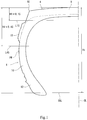
- FIG. 1 shows an outline of the cross-section, of the tire 2, obtained when the tire 2 is cut, at a position represented by a line I in FIG. 2 , by the plane perpendicular to the circumferential direction.
- the tire 2 includes a tread 8, sidewalls 10, clinches 12, beads, a carcass, a belt, and an inner line, which are not shown in detail in FIG. 1 .
- the tread surface 4 is formed from the outer surface of the tread 8.
- the side surface 6 is mainly formed from the outer surface of the sidewall 10.
- the side surface 6 is also formed from a part of the outer surface of each of the clinch 12 and the tread 8.
- the tire 2 is of a tubeless type.
- the tire 2 is mounted to a passenger car.
- the tread surface 4 has grooves 14.
- the groove 14 extends in the axial direction and the circumferential direction so as to be curved.
- a portion, of the tread 8, surrounded by the grooves 14 is referred to as a block 16.
- the tread 8 has multiple blocks 16.
- reference character TE represents a tread end.
- the tread end TE is an outer side end, in the axial direction, of an imaginary tread surface 4 on the assumption that the grooves 14 are not provided.
- reference character PW represents a position on the side surface 6. At the position PW, the tire 2 has the maximum width in the axial direction. The position PW is the maximum width position.
- the tire 2 has a projection 18 on the side surface 6.
- the projection 18 is disposed between the tread end TE and the maximum width position PW.
- a plurality of the projections 18 are aligned in the circumferential direction.
- the projection 18 has a small projection 20 on the outer side surface thereof.
- a raised portion 22 that is tapered is disposed between the projections 18 adjacent to each other. In FIG. 1 , the small projection 20 is not shown.
- the projection 18 includes a groove 29 in an outer side surface 27.
- the groove 29 extends in the circumferential direction.
- the groove 29 extends from one end of the projection 18 to the other end thereof in the circumferential direction.
- the groove 29 extends through the outer side surface 27 in the circumferential direction.
- an alternate long and two short dashes line represents the side surface 6 on the assumption that the projection 18 is not provided.
- a method for producing the tire 2 includes a step of forming a raw cover, and a step of vulcanizing the raw cover.
- the step of forming the raw cover components of the tire 2 are assembled to form the raw cover.
- the step of vulcanizing the raw cover the raw cover is vulcanized in a mold.
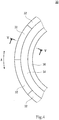
- FIGS. 4 and 5 illustrate an example of a mold 30.
- FIG. 4 is a plan view of the mold 30.
- the direction perpendicular to the surface of the drawing sheet represents the axial direction
- a direction indicated by a double-headed arrow A represents the circumferential direction.
- FIG. 5 is a cross-sectional view taken along a line V-V in FIG. 4 .
- a direction indicated by an arrow X represents the radial direction
- a direction indicated by an arrow Y represents the axial direction
- the direction perpendicular to the surface of the drawing sheet represents the circumferential direction.
- a raw cover R in the mold 30 is also shown.
- the mold 30 includes a plurality of segments 32, a pair of side plates 34, and a pair of bead rings 36. These are referred to as constituent elements of the mold 30.
- the planar shape of the segment 32 is a substantially arc-shape.
- the plurality of segments 32 are arranged so as to be ring-shaped.
- the side plates 34 and the bead rings 36 are each substantially ring-shaped.
- FIG. 5 the mold 30 is closed. In this state, inner surfaces of the segments 32, inner surfaces of the side plates 34, and inner surfaces of the bead rings 36 are combined to form a cavity surface.
- the cavity surface contacts with the raw cover R, to form an outer surface of the tire 2.
- a boundary between adjacent constituent elements on the cavity surface is referred to as a dividing line.
- the projection 18 is disposed between the tread end TE and the maximum width position PW on the side surface 6.
- the projection 18 disposed between the tread end TE and the maximum width position PW contributes to protection of the side surface 6.
- the projection 18 contributes to outer appearance of the tire 2.
- Distortion of the outer side surface 27 of the projection 18 disposed in this region tends to increase.
- the groove 29 effectively reduces distortion of the outer side surface 27 of the projection 18.
- the outer side surface 27 of the projection 18 is prevented from becoming an originating point of damage.
- a ratio (GD/T) of the depth GD to the thickness T is not less than 15%.
- the groove 29 effectively reduces distortion of the outer side surface 27 of the projection 18.
- the ratio (GD/T) is not less than 15%, distortion at the bottom of the groove 29 is inhibited when the side portion is deformed. In the tire 2, the outer side surface 27 and the bottom of the groove 29 in the projection 18 are prevented from becoming originating points of damage.
- the ratio (GD/T) is preferably not less than 20%.
- the ratio (GD/T) is not greater than 30%.
- the ratio (GD/T) is not greater than 30%, the projection 18 can have sufficient cut resistance. When collision against an obstacle or the like occurs, damage to the projection 18 is reduced.
- the ratio (GD/T) is preferably not greater than 25%.
- the thickness T is preferably not less than 4.0 mm.
- the projection 18 effectively contributes to protection of the side surface 6.
- the tire 2 can have excellent cut resistance.
- the projection 18 is likely to be conspicuous.
- the projection 18 effectively contributes to outer appearance of the tire 2.
- the thickness T is more preferably not less than 5.0 mm.
- the thickness T is preferably not greater than 8.0 mm.
- the thickness T is more preferably not greater than 7.0 mm.
- a tire shown in FIG. 1 was produced.
- the size of the tire was 285/70R17.
- the specifications of the projection disposed on the side surface of the tire are indicated in Table 1.
- the tire was produced using the mold shown in FIGS. 4 to 6 .
- the ratio (W/H1) was 15%, and the thickness T was 6 mm.
- a tire of comparative example 1 (abbreviated as "Comp. Ex. 1") was obtained in the same manner as for example 1 except that the projection had no grooves. Since the projection had no grooves, the imaginary line, on the side surface, corresponding to the dividing line did not overlap a groove.
Landscapes
- Engineering & Computer Science (AREA)
- Mechanical Engineering (AREA)
- Tires In General (AREA)
- Moulds For Moulding Plastics Or The Like (AREA)
Claims (5)
- Reifen (2) mit:einem Vorsprung (18), der auf einer Seitenfläche (6) des Reifens (2) zwischen einem Laufflächenende (TE) und einer Position maximaler Breite (PW) angeordnet ist, wobeider Vorsprung (18) eine einzelne Nut (29) aufweist, die sich in einer Umfangsrichtung (A) durch eine äußere Seitenfläche (27) des Vorsprungs (18) erstreckt, unddie Nut (29) in einem Bereich angeordnet ist, in dem ein Abstand von einem äußeren Seitenende des Reifens (2) 15% bis 45% einer Querschnittshöhe (H1) des Reifens (2) in einer radialen Richtung (X) beträgt,dadurch gekennzeichnet, dasseine Breite (GW) der Nut (29) nicht weniger als 1,5 mm und nicht mehr als 3,0 mm beträgt undeine Tiefe (GD) der Nut (29) nicht weniger als 15% einer Dicke (T) des Vorsprungs (18) und nicht mehr als 30% der Dicke (T) des Vorsprungs (18) beträgt.
- Reifen (2) nach Anspruch 1, wobei ein Verhältnis (Wi/Wo) einer Breite Wi eines Abschnitts des Vorsprungs (18), der in einer radialen Richtung (X) innerhalb der Nut (29) angeordnet ist, bezogen auf eine Breite Wo eines Abschnitts des Vorsprungs (18), der in der radialen Richtung (X) außerhalb der Nut (29) angeordnet ist, nicht weniger als 1,5 und nicht mehr als 2,5 beträgt.
- Reifen (2) nach Anspruch 1, wobei ein Verhältnis (Ti/To) einer Dicke Ti eines Abschnitts des Vorsprungs (18), der in einer radialen Richtung (X) innerhalb der Nut (29) angeordnet ist, bezogen auf eine Dicke To eines Abschnitts des Vorsprungs (18), der in der radialen Richtung (X) außerhalb der Nut (29) angeordnet ist, nicht weniger als 0,95 und nicht mehr als 1,05 beträgt.
- Reifen (2) nach Anspruch 1, wobei
der Reifen (2) unter Verwendung einer Form (30) hergestellt ist, die einen ersten Teil (32) und einen zweiten Teil (34) hat und zwischen dem ersten Teil (32) und dem zweiten Teil (34) eine Trennlinie (42) hat, die sich in der Umfangsrichtung (A) erstreckt und mit der Seitenfläche (6) in Kontakt kommt, und
die Nut (29) eine gedachte Linie auf der Seitenfläche (6) überlappt, die der Trennlinie (42) entspricht. - Verfahren zur Herstellung des Reifens (2) gemäß Anspruch 1, wobei das Verfahren Folgendes umfasst:(1) einen Schritt, in dem eine Rohdecke (R) für den Reifen (2) ausgebildet wird; und(2) einen Schritt, in dem die Rohdecke (R) vulkanisiert wird, wobeidie Rohdecke (R) in dem Schritt (2) in einer Form (30) unter Druck gesetzt und erhitzt wird, welche einen ersten Teil (32) und einen zweiten Teil (34) hat, die mit der Seitenfläche (6) in Kontakt kommen, welche zwischen dem ersten Teil (32) und dem zweiten Teil (34) eine Trennlinie (42) hat, die sich in einer Umfangsrichtung (A) erstreckt, welche einen Überstand (48) hat, der sich in der Umfangsrichtung (A) erstreckt, um auf der äußere Seitenfläche (27) des Vorsprungs (18) die Nut (29) auszubilden, die sich in der Umfangsrichtung (A) erstreckt, und welche die Trennlinie (42) derart angeordnet hat, dass die Trennlinie (42) den Überstand (48) überlappt.
Applications Claiming Priority (1)
| Application Number | Priority Date | Filing Date | Title |
|---|---|---|---|
| JP2018037221A JP7091715B2 (ja) | 2018-03-02 | 2018-03-02 | タイヤ |
Publications (2)
| Publication Number | Publication Date |
|---|---|
| EP3533639A1 EP3533639A1 (de) | 2019-09-04 |
| EP3533639B1 true EP3533639B1 (de) | 2020-12-30 |
Family
ID=65494000
Family Applications (1)
| Application Number | Title | Priority Date | Filing Date |
|---|---|---|---|
| EP19157939.0A Active EP3533639B1 (de) | 2018-03-02 | 2019-02-19 | Reifen |
Country Status (4)
| Country | Link |
|---|---|
| US (1) | US11400761B2 (de) |
| EP (1) | EP3533639B1 (de) |
| JP (1) | JP7091715B2 (de) |
| CN (1) | CN110217053A (de) |
Families Citing this family (2)
| Publication number | Priority date | Publication date | Assignee | Title |
|---|---|---|---|---|
| DE102019217828A1 (de) * | 2019-11-19 | 2021-05-20 | Continental Reifen Deutschland Gmbh | Nutzfahrzeugreifen |
| JP7619881B2 (ja) * | 2021-04-26 | 2025-01-22 | Toyo Tire株式会社 | 空気入りタイヤ |
Citations (1)
| Publication number | Priority date | Publication date | Assignee | Title |
|---|---|---|---|---|
| US20120073719A1 (en) * | 2010-09-24 | 2012-03-29 | Hiroyuki Kurosawa | Pneumatic tire |
Family Cites Families (31)
| Publication number | Priority date | Publication date | Assignee | Title |
|---|---|---|---|---|
| GB1188287A (en) * | 1966-07-13 | 1970-04-15 | Dunlop Co Ltd | Improvements in or relating to Tyres |
| US4144921A (en) * | 1976-03-03 | 1979-03-20 | Nissan Motor Company, Limited | Pneumatic tire with an internal damage indicator |
| JPS599361B2 (ja) * | 1976-04-23 | 1984-03-02 | 日産自動車株式会社 | 空気入りタイヤ |
| JP2955202B2 (ja) * | 1995-02-13 | 1999-10-04 | 住友ゴム工業株式会社 | 空気入りタイヤ |
| AU6135699A (en) * | 1999-09-03 | 2001-04-10 | Goodyear Tire And Rubber Company, The | Farm implement tire |
| JP3337453B2 (ja) * | 2000-02-15 | 2002-10-21 | 住友ゴム工業株式会社 | 空気入りタイヤ |
| US6920906B2 (en) * | 2001-08-31 | 2005-07-26 | Bridgestone/Firestone North American Tire, Llc | Pneumatic tire with sidewall projections |
| JP4048058B2 (ja) * | 2002-01-25 | 2008-02-13 | 株式会社ブリヂストン | 空気入りタイヤ |
| US20040055683A1 (en) * | 2002-09-19 | 2004-03-25 | Feider Georges Gaston | Truck steer tire, a mold and a method of molding |
| JP4293427B2 (ja) * | 2003-04-09 | 2009-07-08 | 東洋ゴム工業株式会社 | 空気入りタイヤ |
| JP4826110B2 (ja) * | 2005-03-16 | 2011-11-30 | 横浜ゴム株式会社 | 空気入りラジアルタイヤ |
| JP2007022367A (ja) * | 2005-07-19 | 2007-02-01 | Yokohama Rubber Co Ltd:The | 空気入りタイヤ |
| JP2007050825A (ja) * | 2005-08-19 | 2007-03-01 | Toyo Tire & Rubber Co Ltd | 空気入りタイヤ |
| JP5027549B2 (ja) * | 2007-04-06 | 2012-09-19 | 住友ゴム工業株式会社 | 空気入りタイヤ、及びそれに作用する力の検出方法 |
| JP2010125886A (ja) * | 2008-11-25 | 2010-06-10 | Bridgestone Corp | 空気入りタイヤ |
| KR20110006462A (ko) * | 2009-07-14 | 2011-01-20 | 금호타이어 주식회사 | 중하중용 공기입 타이어 |
| DE102010015845A1 (de) * | 2010-03-08 | 2011-09-08 | Continental Reifen Deutschland Gmbh | Fahrzeugluftreifen |
| JP2012006499A (ja) | 2010-06-25 | 2012-01-12 | Yokohama Rubber Co Ltd:The | 空気入りタイヤ及びその製造方法 |
| JP6050568B2 (ja) * | 2011-06-20 | 2016-12-21 | 株式会社ブリヂストン | 空気入りタイヤ |
| JP2013082262A (ja) * | 2011-10-06 | 2013-05-09 | Toyo Tire & Rubber Co Ltd | 空気入りタイヤ |
| JP2013159233A (ja) * | 2012-02-06 | 2013-08-19 | Bridgestone Corp | タイヤ |
| JP6035935B2 (ja) * | 2012-07-18 | 2016-11-30 | 横浜ゴム株式会社 | プレキュア更生タイヤおよびプレキュア更生タイヤの製造方法 |
| JP6085940B2 (ja) * | 2012-10-11 | 2017-03-01 | 横浜ゴム株式会社 | 更生タイヤ |
| DE102014206912A1 (de) * | 2014-04-10 | 2015-10-15 | Continental Reifen Deutschland Gmbh | Fahrzeugluftreifen |
| DE102014214988A1 (de) * | 2014-07-30 | 2016-02-04 | Continental Reifen Deutschland Gmbh | Reifen in Diagonalbauart |
| FR3027256A1 (fr) * | 2014-10-21 | 2016-04-22 | Michelin & Cie | Dispositif de protection dun flanc de pneu |
| JP6487758B2 (ja) * | 2015-04-14 | 2019-03-20 | 住友ゴム工業株式会社 | タイヤ加硫金型、それを用いた空気入りタイヤの製造方法、及び、空気入りタイヤ |
| FR3044970A1 (fr) * | 2015-12-10 | 2017-06-16 | Michelin & Cie | Dispositif continu de protection dun flanc de pneu. |
| JP6786962B2 (ja) | 2016-08-30 | 2020-11-18 | 株式会社豊田自動織機 | 電池パックの端子取付構造 |
| JP6946641B2 (ja) * | 2016-12-12 | 2021-10-06 | 住友ゴム工業株式会社 | 空気入りタイヤ |
| JP6347293B1 (ja) * | 2017-01-17 | 2018-06-27 | 横浜ゴム株式会社 | 空気入りタイヤ |
-
2018
- 2018-03-02 JP JP2018037221A patent/JP7091715B2/ja active Active
-
2019
- 2019-02-19 EP EP19157939.0A patent/EP3533639B1/de active Active
- 2019-02-20 CN CN201910125294.3A patent/CN110217053A/zh active Pending
- 2019-02-21 US US16/281,664 patent/US11400761B2/en active Active
Patent Citations (1)
| Publication number | Priority date | Publication date | Assignee | Title |
|---|---|---|---|---|
| US20120073719A1 (en) * | 2010-09-24 | 2012-03-29 | Hiroyuki Kurosawa | Pneumatic tire |
Also Published As
| Publication number | Publication date |
|---|---|
| JP7091715B2 (ja) | 2022-06-28 |
| EP3533639A1 (de) | 2019-09-04 |
| US20190270343A1 (en) | 2019-09-05 |
| JP2019151192A (ja) | 2019-09-12 |
| US11400761B2 (en) | 2022-08-02 |
| CN110217053A (zh) | 2019-09-10 |
Similar Documents
| Publication | Publication Date | Title |
|---|---|---|
| EP2700513B1 (de) | Notlaufreifen | |
| EP3556573B1 (de) | Reifen | |
| EP3318424B1 (de) | Luftreifen | |
| EP3202594B1 (de) | Luftreifen | |
| EP2939854B1 (de) | Luftreifen | |
| EP3219515B1 (de) | Luftreifen | |
| EP3202595B1 (de) | Luftreifen | |
| EP3293018B1 (de) | Reifen für schwerlastfahrzeug | |
| EP3332991B1 (de) | Luftreifen | |
| EP3231634B1 (de) | Luftreifen | |
| EP3173257B1 (de) | Notlaufreifen | |
| EP3695988B1 (de) | Luftreifen, reifenform und verfahren zur herstellung eines luftreifens unter verwendung davon | |
| EP3360699B1 (de) | Schwerlastreifen und verfahren zur herstellung davon | |
| EP3521068B1 (de) | Reifen für zweirädriges fahrzeug | |
| EP3533639B1 (de) | Reifen | |
| EP3501850B1 (de) | Reifen | |
| EP3315325B1 (de) | Luftreifen | |
| EP2562008A2 (de) | LKW-Luftreifen | |
| EP3315324B1 (de) | Luftreifen | |
| EP3769974B1 (de) | Schwerlastluftreifen | |
| EP3132949A1 (de) | Luftreifen | |
| EP3251876B1 (de) | Luftreifen | |
| EP3613613B1 (de) | Luftreifen | |
| EP3189988B1 (de) | Luftreifen | |
| EP4321351B1 (de) | Reifen |
Legal Events
| Date | Code | Title | Description |
|---|---|---|---|
| PUAI | Public reference made under article 153(3) epc to a published international application that has entered the european phase |
Free format text: ORIGINAL CODE: 0009012 |
|
| STAA | Information on the status of an ep patent application or granted ep patent |
Free format text: STATUS: THE APPLICATION HAS BEEN PUBLISHED |
|
| AK | Designated contracting states |
Kind code of ref document: A1 Designated state(s): AL AT BE BG CH CY CZ DE DK EE ES FI FR GB GR HR HU IE IS IT LI LT LU LV MC MK MT NL NO PL PT RO RS SE SI SK SM TR |
|
| AX | Request for extension of the european patent |
Extension state: BA ME |
|
| STAA | Information on the status of an ep patent application or granted ep patent |
Free format text: STATUS: REQUEST FOR EXAMINATION WAS MADE |
|
| 17P | Request for examination filed |
Effective date: 20190919 |
|
| STAA | Information on the status of an ep patent application or granted ep patent |
Free format text: STATUS: EXAMINATION IS IN PROGRESS |
|
| 17Q | First examination report despatched |
Effective date: 20200225 |
|
| GRAP | Despatch of communication of intention to grant a patent |
Free format text: ORIGINAL CODE: EPIDOSNIGR1 |
|
| STAA | Information on the status of an ep patent application or granted ep patent |
Free format text: STATUS: GRANT OF PATENT IS INTENDED |
|
| INTG | Intention to grant announced |
Effective date: 20201014 |
|
| GRAS | Grant fee paid |
Free format text: ORIGINAL CODE: EPIDOSNIGR3 |
|
| GRAA | (expected) grant |
Free format text: ORIGINAL CODE: 0009210 |
|
| STAA | Information on the status of an ep patent application or granted ep patent |
Free format text: STATUS: THE PATENT HAS BEEN GRANTED |
|
| AK | Designated contracting states |
Kind code of ref document: B1 Designated state(s): AL AT BE BG CH CY CZ DE DK EE ES FI FR GB GR HR HU IE IS IT LI LT LU LV MC MK MT NL NO PL PT RO RS SE SI SK SM TR |
|
| REG | Reference to a national code |
Ref country code: GB Ref legal event code: FG4D |
|
| REG | Reference to a national code |
Ref country code: DE Ref legal event code: R096 Ref document number: 602019001911 Country of ref document: DE |
|
| REG | Reference to a national code |
Ref country code: AT Ref legal event code: REF Ref document number: 1349574 Country of ref document: AT Kind code of ref document: T Effective date: 20210115 |
|
| REG | Reference to a national code |
Ref country code: IE Ref legal event code: FG4D |
|
| PG25 | Lapsed in a contracting state [announced via postgrant information from national office to epo] |
Ref country code: GR Free format text: LAPSE BECAUSE OF FAILURE TO SUBMIT A TRANSLATION OF THE DESCRIPTION OR TO PAY THE FEE WITHIN THE PRESCRIBED TIME-LIMIT Effective date: 20210331 Ref country code: NO Free format text: LAPSE BECAUSE OF FAILURE TO SUBMIT A TRANSLATION OF THE DESCRIPTION OR TO PAY THE FEE WITHIN THE PRESCRIBED TIME-LIMIT Effective date: 20210330 Ref country code: FI Free format text: LAPSE BECAUSE OF FAILURE TO SUBMIT A TRANSLATION OF THE DESCRIPTION OR TO PAY THE FEE WITHIN THE PRESCRIBED TIME-LIMIT Effective date: 20201230 Ref country code: RS Free format text: LAPSE BECAUSE OF FAILURE TO SUBMIT A TRANSLATION OF THE DESCRIPTION OR TO PAY THE FEE WITHIN THE PRESCRIBED TIME-LIMIT Effective date: 20201230 |
|
| REG | Reference to a national code |
Ref country code: AT Ref legal event code: MK05 Ref document number: 1349574 Country of ref document: AT Kind code of ref document: T Effective date: 20201230 |
|
| PG25 | Lapsed in a contracting state [announced via postgrant information from national office to epo] |
Ref country code: LV Free format text: LAPSE BECAUSE OF FAILURE TO SUBMIT A TRANSLATION OF THE DESCRIPTION OR TO PAY THE FEE WITHIN THE PRESCRIBED TIME-LIMIT Effective date: 20201230 Ref country code: SE Free format text: LAPSE BECAUSE OF FAILURE TO SUBMIT A TRANSLATION OF THE DESCRIPTION OR TO PAY THE FEE WITHIN THE PRESCRIBED TIME-LIMIT Effective date: 20201230 Ref country code: BG Free format text: LAPSE BECAUSE OF FAILURE TO SUBMIT A TRANSLATION OF THE DESCRIPTION OR TO PAY THE FEE WITHIN THE PRESCRIBED TIME-LIMIT Effective date: 20210330 |
|
| REG | Reference to a national code |
Ref country code: NL Ref legal event code: MP Effective date: 20201230 |
|
| PG25 | Lapsed in a contracting state [announced via postgrant information from national office to epo] |
Ref country code: HR Free format text: LAPSE BECAUSE OF FAILURE TO SUBMIT A TRANSLATION OF THE DESCRIPTION OR TO PAY THE FEE WITHIN THE PRESCRIBED TIME-LIMIT Effective date: 20201230 |
|
| REG | Reference to a national code |
Ref country code: LT Ref legal event code: MG9D |
|
| PG25 | Lapsed in a contracting state [announced via postgrant information from national office to epo] |
Ref country code: CZ Free format text: LAPSE BECAUSE OF FAILURE TO SUBMIT A TRANSLATION OF THE DESCRIPTION OR TO PAY THE FEE WITHIN THE PRESCRIBED TIME-LIMIT Effective date: 20201230 Ref country code: SK Free format text: LAPSE BECAUSE OF FAILURE TO SUBMIT A TRANSLATION OF THE DESCRIPTION OR TO PAY THE FEE WITHIN THE PRESCRIBED TIME-LIMIT Effective date: 20201230 Ref country code: EE Free format text: LAPSE BECAUSE OF FAILURE TO SUBMIT A TRANSLATION OF THE DESCRIPTION OR TO PAY THE FEE WITHIN THE PRESCRIBED TIME-LIMIT Effective date: 20201230 Ref country code: LT Free format text: LAPSE BECAUSE OF FAILURE TO SUBMIT A TRANSLATION OF THE DESCRIPTION OR TO PAY THE FEE WITHIN THE PRESCRIBED TIME-LIMIT Effective date: 20201230 Ref country code: RO Free format text: LAPSE BECAUSE OF FAILURE TO SUBMIT A TRANSLATION OF THE DESCRIPTION OR TO PAY THE FEE WITHIN THE PRESCRIBED TIME-LIMIT Effective date: 20201230 Ref country code: PT Free format text: LAPSE BECAUSE OF FAILURE TO SUBMIT A TRANSLATION OF THE DESCRIPTION OR TO PAY THE FEE WITHIN THE PRESCRIBED TIME-LIMIT Effective date: 20210430 |
|
| PG25 | Lapsed in a contracting state [announced via postgrant information from national office to epo] |
Ref country code: AT Free format text: LAPSE BECAUSE OF FAILURE TO SUBMIT A TRANSLATION OF THE DESCRIPTION OR TO PAY THE FEE WITHIN THE PRESCRIBED TIME-LIMIT Effective date: 20201230 Ref country code: PL Free format text: LAPSE BECAUSE OF FAILURE TO SUBMIT A TRANSLATION OF THE DESCRIPTION OR TO PAY THE FEE WITHIN THE PRESCRIBED TIME-LIMIT Effective date: 20201230 |
|
| PG25 | Lapsed in a contracting state [announced via postgrant information from national office to epo] |
Ref country code: IS Free format text: LAPSE BECAUSE OF FAILURE TO SUBMIT A TRANSLATION OF THE DESCRIPTION OR TO PAY THE FEE WITHIN THE PRESCRIBED TIME-LIMIT Effective date: 20210430 Ref country code: MC Free format text: LAPSE BECAUSE OF FAILURE TO SUBMIT A TRANSLATION OF THE DESCRIPTION OR TO PAY THE FEE WITHIN THE PRESCRIBED TIME-LIMIT Effective date: 20201230 |
|
| REG | Reference to a national code |
Ref country code: DE Ref legal event code: R097 Ref document number: 602019001911 Country of ref document: DE |
|
| REG | Reference to a national code |
Ref country code: BE Ref legal event code: MM Effective date: 20210228 |
|
| PG25 | Lapsed in a contracting state [announced via postgrant information from national office to epo] |
Ref country code: IT Free format text: LAPSE BECAUSE OF FAILURE TO SUBMIT A TRANSLATION OF THE DESCRIPTION OR TO PAY THE FEE WITHIN THE PRESCRIBED TIME-LIMIT Effective date: 20201230 Ref country code: LU Free format text: LAPSE BECAUSE OF NON-PAYMENT OF DUE FEES Effective date: 20210219 Ref country code: AL Free format text: LAPSE BECAUSE OF FAILURE TO SUBMIT A TRANSLATION OF THE DESCRIPTION OR TO PAY THE FEE WITHIN THE PRESCRIBED TIME-LIMIT Effective date: 20201230 |
|
| PLBE | No opposition filed within time limit |
Free format text: ORIGINAL CODE: 0009261 |
|
| STAA | Information on the status of an ep patent application or granted ep patent |
Free format text: STATUS: NO OPPOSITION FILED WITHIN TIME LIMIT |
|
| PG25 | Lapsed in a contracting state [announced via postgrant information from national office to epo] |
Ref country code: DK Free format text: LAPSE BECAUSE OF FAILURE TO SUBMIT A TRANSLATION OF THE DESCRIPTION OR TO PAY THE FEE WITHIN THE PRESCRIBED TIME-LIMIT Effective date: 20201230 |
|
| 26N | No opposition filed |
Effective date: 20211001 |
|
| PG25 | Lapsed in a contracting state [announced via postgrant information from national office to epo] |
Ref country code: ES Free format text: LAPSE BECAUSE OF FAILURE TO SUBMIT A TRANSLATION OF THE DESCRIPTION OR TO PAY THE FEE WITHIN THE PRESCRIBED TIME-LIMIT Effective date: 20201230 Ref country code: IE Free format text: LAPSE BECAUSE OF NON-PAYMENT OF DUE FEES Effective date: 20210219 |
|
| PG25 | Lapsed in a contracting state [announced via postgrant information from national office to epo] |
Ref country code: SI Free format text: LAPSE BECAUSE OF FAILURE TO SUBMIT A TRANSLATION OF THE DESCRIPTION OR TO PAY THE FEE WITHIN THE PRESCRIBED TIME-LIMIT Effective date: 20201230 |
|
| PG25 | Lapsed in a contracting state [announced via postgrant information from national office to epo] |
Ref country code: IS Free format text: LAPSE BECAUSE OF FAILURE TO SUBMIT A TRANSLATION OF THE DESCRIPTION OR TO PAY THE FEE WITHIN THE PRESCRIBED TIME-LIMIT Effective date: 20210430 |
|
| PG25 | Lapsed in a contracting state [announced via postgrant information from national office to epo] |
Ref country code: BE Free format text: LAPSE BECAUSE OF NON-PAYMENT OF DUE FEES Effective date: 20210228 |
|
| REG | Reference to a national code |
Ref country code: CH Ref legal event code: PL |
|
| PG25 | Lapsed in a contracting state [announced via postgrant information from national office to epo] |
Ref country code: LI Free format text: LAPSE BECAUSE OF NON-PAYMENT OF DUE FEES Effective date: 20220228 Ref country code: CH Free format text: LAPSE BECAUSE OF NON-PAYMENT OF DUE FEES Effective date: 20220228 |
|
| PG25 | Lapsed in a contracting state [announced via postgrant information from national office to epo] |
Ref country code: NL Free format text: LAPSE BECAUSE OF NON-PAYMENT OF DUE FEES Effective date: 20201230 Ref country code: CY Free format text: LAPSE BECAUSE OF FAILURE TO SUBMIT A TRANSLATION OF THE DESCRIPTION OR TO PAY THE FEE WITHIN THE PRESCRIBED TIME-LIMIT Effective date: 20201230 |
|
| PG25 | Lapsed in a contracting state [announced via postgrant information from national office to epo] |
Ref country code: SM Free format text: LAPSE BECAUSE OF FAILURE TO SUBMIT A TRANSLATION OF THE DESCRIPTION OR TO PAY THE FEE WITHIN THE PRESCRIBED TIME-LIMIT Effective date: 20201230 Ref country code: HU Free format text: LAPSE BECAUSE OF FAILURE TO SUBMIT A TRANSLATION OF THE DESCRIPTION OR TO PAY THE FEE WITHIN THE PRESCRIBED TIME-LIMIT; INVALID AB INITIO Effective date: 20190219 |
|
| GBPC | Gb: european patent ceased through non-payment of renewal fee |
Effective date: 20230219 |
|
| PG25 | Lapsed in a contracting state [announced via postgrant information from national office to epo] |
Ref country code: GB Free format text: LAPSE BECAUSE OF NON-PAYMENT OF DUE FEES Effective date: 20230219 |
|
| PG25 | Lapsed in a contracting state [announced via postgrant information from national office to epo] |
Ref country code: GB Free format text: LAPSE BECAUSE OF NON-PAYMENT OF DUE FEES Effective date: 20230219 |
|
| PG25 | Lapsed in a contracting state [announced via postgrant information from national office to epo] |
Ref country code: MK Free format text: LAPSE BECAUSE OF FAILURE TO SUBMIT A TRANSLATION OF THE DESCRIPTION OR TO PAY THE FEE WITHIN THE PRESCRIBED TIME-LIMIT Effective date: 20201230 |
|
| PG25 | Lapsed in a contracting state [announced via postgrant information from national office to epo] |
Ref country code: TR Free format text: LAPSE BECAUSE OF FAILURE TO SUBMIT A TRANSLATION OF THE DESCRIPTION OR TO PAY THE FEE WITHIN THE PRESCRIBED TIME-LIMIT Effective date: 20201230 |
|
| PG25 | Lapsed in a contracting state [announced via postgrant information from national office to epo] |
Ref country code: MT Free format text: LAPSE BECAUSE OF FAILURE TO SUBMIT A TRANSLATION OF THE DESCRIPTION OR TO PAY THE FEE WITHIN THE PRESCRIBED TIME-LIMIT Effective date: 20201230 |
|
| PGFP | Annual fee paid to national office [announced via postgrant information from national office to epo] |
Ref country code: FR Payment date: 20251231 Year of fee payment: 8 |
|
| PGFP | Annual fee paid to national office [announced via postgrant information from national office to epo] |
Ref country code: DE Payment date: 20251230 Year of fee payment: 8 |