EP3533596A1 - Verfahren und vorrichtung zum aufkleben eines bandartigen elements auf eine reifeninnenfläche - Google Patents
Verfahren und vorrichtung zum aufkleben eines bandartigen elements auf eine reifeninnenfläche Download PDFInfo
- Publication number
- EP3533596A1 EP3533596A1 EP17864610.5A EP17864610A EP3533596A1 EP 3533596 A1 EP3533596 A1 EP 3533596A1 EP 17864610 A EP17864610 A EP 17864610A EP 3533596 A1 EP3533596 A1 EP 3533596A1
- Authority
- EP
- European Patent Office
- Prior art keywords
- tire
- band
- attaching
- rotary drum
- outer circumferential
- Prior art date
- Legal status (The legal status is an assumption and is not a legal conclusion. Google has not performed a legal analysis and makes no representation as to the accuracy of the status listed.)
- Withdrawn
Links
- 238000000034 method Methods 0.000 title claims abstract description 14
- 238000005096 rolling process Methods 0.000 claims abstract description 8
- 238000004804 winding Methods 0.000 claims abstract description 5
- 239000000463 material Substances 0.000 description 5
- 238000010586 diagram Methods 0.000 description 4
- 238000005520 cutting process Methods 0.000 description 3
- 239000011347 resin Substances 0.000 description 2
- 229920005989 resin Polymers 0.000 description 2
- 230000000694 effects Effects 0.000 description 1
- 239000002184 metal Substances 0.000 description 1
- 239000011148 porous material Substances 0.000 description 1
Images


Classifications
-
- B—PERFORMING OPERATIONS; TRANSPORTING
- B29—WORKING OF PLASTICS; WORKING OF SUBSTANCES IN A PLASTIC STATE IN GENERAL
- B29D—PRODUCING PARTICULAR ARTICLES FROM PLASTICS OR FROM SUBSTANCES IN A PLASTIC STATE
- B29D30/00—Producing pneumatic or solid tyres or parts thereof
- B29D30/06—Pneumatic tyres or parts thereof (e.g. produced by casting, moulding, compression moulding, injection moulding, centrifugal casting)
- B29D30/0681—Parts of pneumatic tyres; accessories, auxiliary operations
- B29D2030/0682—Inner liners
-
- B—PERFORMING OPERATIONS; TRANSPORTING
- B29—WORKING OF PLASTICS; WORKING OF SUBSTANCES IN A PLASTIC STATE IN GENERAL
- B29D—PRODUCING PARTICULAR ARTICLES FROM PLASTICS OR FROM SUBSTANCES IN A PLASTIC STATE
- B29D30/00—Producing pneumatic or solid tyres or parts thereof
- B29D30/0061—Accessories, details or auxiliary operations not otherwise provided for
-
- B—PERFORMING OPERATIONS; TRANSPORTING
- B60—VEHICLES IN GENERAL
- B60C—VEHICLE TYRES; TYRE INFLATION; TYRE CHANGING; CONNECTING VALVES TO INFLATABLE ELASTIC BODIES IN GENERAL; DEVICES OR ARRANGEMENTS RELATED TO TYRES
- B60C5/00—Inflatable pneumatic tyres or inner tubes
Definitions
- the present invention relates to an attaching apparatus and an attaching method for attaching a band-like member to a tire inner surface, and specifically relates to an attaching apparatus and an attaching method capable of efficiently attaching a band-like member such as a sound absorbing member to a tire inner surface.
- cavernous resonance caused by the vibration of the air in the tire is one cause of tire noise.
- uneven road surfaces cause a tread portion to vibrate.
- the vibrations of the tread portion cause the air inside the tire to vibrate which causes cavernous resonance to be generated.
- a band-like sound absorbing member made of a porous material is attached in a tire circumferential direction of a tire inner surface (see, for example, Patent Document 1).
- Patent Document 1 JP 2007-168243 A
- An object of the present invention is to provide an attaching apparatus and an attaching method capable of efficiently attaching a band-like member such as a sound absorbing member to a tire inner surface.
- an attaching apparatus for attaching a band-like member to a tire inner surface of an embodiment of the present invention comprises: a traveling roller that rolls on the inner surface of the tire in a circumferential direction; a rotary drum disposed on an inner side of the tire, whose outer circumferential surface is opposed to the inner surface of the tire with an interval therebetween; a guide portion that introduces and winds a band-like member supplied from an outside of the tire onto the outer circumferential surface of the rotary drum in rotation; the rotary drum being rotationally driven by rotation of the rolling traveling roller; and the band-like member being compression-bonded and attached to the inner surface of the tire by the outer circumferential surface of the rotary drum.
- An attaching method of a band-like member to a tire inner surface of an embodiment of the present invention comprises: disposing, on an inner side of the tire, a traveling roller, and a rotary drum whose outer circumferential surface is opposed to the inner surface of the tire with an interval therebetween; rotationally driving the rotary drum by rotation of the rolling traveling roller; introducing and winding a band-like member supplied from an outside of the tire onto the outer circumferential surface of the rotary drum in rotation via a guide portion; and compression-bonding and attaching the band-like member to the inner surface of the tire by the outer circumferential surface of the rotary drum.
- a band-like member can be continuously introduced and wound from an outside of a tire via a guide portion onto an outer circumferential surface of a rotary drum rotationally driven by the rotation of a traveling roller rotating on an inner surface of the tire.
- the band-like member can be continuously compression-bonded and attached to the inner surface of the tire by the outer circumferential surface of the rotary drum in rotation. Accordingly, it is unnecessary to cut by the attaching length and to wind the band-like member for each tire in advance. Accordingly, it is possible to improve the efficiency of attaching work while reducing man-hours.
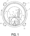
- An attaching apparatus 1 for attaching a band-like member to a tire inner surface of an embodiment of the present invention exemplified in FIGS. 1 to 4 is used when a band-like member B such as a sound absorbing member is attached to an inner surface Ta of a tire T (hereinafter, referred to as the "tire inner surface Ta").
- the tire inner surface Ta is a surface corresponding to an inner circumferential side of a tread surface of the tire T.
- an adhering surface disposed on one surface of the band-like member B is covered with a release paper P.
- CL in the drawing indicates a tire axis extending in a tire lateral direction with respect to the center of the tire T in a side view.
- the attaching apparatus 1 includes a traveling roller 2 and a rotary drum 3 disposed on an inner side of the tire T, and a guide portion 6.
- the attaching apparatus 1 includes a case 8 covering the rotary drum 3.
- the shape of the case 8 is not particularly limited, but is, for example, a shaped formed along the outer shape of the rotary drum 3 as in this embodiment.
- An inlet 8a for receiving the band-like member B into the case 8 is formed on an upper portion of the case 8.
- An outlet 8b for feeding the band-like member B from the inside to the outside of the case 8 is formed on a lower portion of the case 8.
- a support arm 9 extending in the tire axial direction is attached to an upper end portion of the case 8.
- the traveling roller 2 is attached to a support shaft 2a extending outward in the tire axial direction of the case 8 from one side surface in the tire axial direction. Accordingly, the traveling roller 2 is rotatably supported with respect to the case 8 on the outer side of the one side surface of the case 8.
- the traveling roller 2 rotates on the tire inner surface Ta in a circumferential direction with an outer circumferential surface thereof in contact with the tire inner surface Ta.
- a traveling roller gear 2b having a smaller diameter than the traveling roller 2 is connected to one side of the traveling roller 2 in the width direction. The traveling roller 2 and the traveling roller gear 2b integrally rotate.
- the outer circumferential surface of the traveling roller 2 may be made of a material unlikely to slip with respect to the tire inner surface Ta, such as rubber or resin.
- the traveling roller 2 is provided only on the outer side of the one side surface of the case 8, but the traveling roller 2 may be provided on the outer sides of both side surfaces of the case 8.
- the rotary drum 3 is a cylindrical body or a columnar body formed of metal, resin, or the like.
- a center shaft 3a of the rotary drum 3 extends in the tire axial direction and is supported by both side surfaces of the case 8.
- the rotary drum 3 supported by the case 8 in this manner rotates about the center shaft 3a.
- An outer circumferential surface of the rotary drum 3 is opposed to the tire inner surface Ta with an interval therebetween.
- a lower portion of the rotary drum 3 protrudes downward and is exposed from the case 8.
- the band-like member B supplied from the outside of the tire T is introduced and wound onto the outer circumferential surface of the rotary drum 3 via the guide portion 6.
- One end side of the center shaft 3a extends to the outside of the case 8, and a rotary drive gear 4 is attached to the one end side. Accordingly, the rotary drive gear 4 disposed on the outer side of one side surface of the case 8 rotates about the center shaft 3a together with the rotary drum 3.
- a transfer gear 5 is rotatably supported on the outer side of the one side surface of the case 8.
- the transfer gear 5 is interposed between the rotary drive gear 4 and the traveling roller gear 2b and meshes with each. Accordingly, rotation directions of the traveling roller 2 and the transfer gear 5 are opposite directions, and rotation directions of the traveling roller 2 and the rotation drum 3 are the same direction.
- the rotary drum 3 is rotationally driven by rotation of the traveling roller 2 rolling on the tire inner surface Ta.
- the gear ratio between each of the rotary drive gear 4, the traveling roller gear 2b, and the transfer gear 5 is determined as appropriate.
- the rotary drive gear 4, the traveling roller gear 2b, and the transfer gear 5 may be, for example, prepared in plurality.
- the plurality of prepared gears have respectively different numbers of teeth, and the ratio of the rotational speed of the rotary drum 3 to the rotational speed of the traveling roller 2 (the rotation ratio) can be changed by changing the combination of the respective gears used together (the gear ratio).
- the rotary drive gear 4, the traveling roller gear 2b, and the transfer gear 5 function as an adjustment unit for adjusting a tension of the band-like member B supplied from the outside of the tire T.
- a large number of projection portions 3b are provided on the outer circumferential surface of the rotary drum 3 at an interval in the circumferential direction.
- the projection portions 3b are provided in plurality and in parallel in the width direction of the rotary drum 3 (the tire axial direction).
- Each of the projection portions 3b bites one surface of the band-like member B introduced onto the outer circumferential surface of the rotary drum 3. Since the projection height of the projection portions 3b from the outer circumferential surface of the rotary drum 3 is set to be smaller than the thickness of the band-like member B, the projection portions 3b do not penetrate the band-like member B in the thickness direction.
- the projection height of the projection portions 3b is, for example, about 1 mm to 5 mm.
- the number of the projection portions 3b is determined as appropriate, but a large number of projections 3b are preferably arranged at an equal interval in the circumferential direction.
- the number of parallel projection portions 3b is set in accordance with the width of the rotary drum 3 or the band-like member B, and thus may be either one row or a plurality of rows.
- the shape of the projection portions 3b is, for example, a conical shape, or a polygonal pyramid shape such as a triangular pyramid shape or a quadrangular pyramid shape.
- the guide portion 6 is attached in the vicinity of the introduction port 8a so as to project to the outside of the case 8.
- the guide portion 6 is a guide member through which the band-like member B passes.
- the guide portion 6 has a function of forcibly changing the advancement direction of the band-like member B sent in the longitudinal direction from the outside of the tire T so as to introduce the band-like member B toward the outer circumferential surface of the rotary drum 3.
- the guide portion 6 can be completely fixed to the case 8, and can also be made movable so that the receiving direction and the introducing direction onto the rotary drum 3 of the band-like member B can be changed.
- a disc-shaped positioning plate 7 attached to the center shaft 3a is disposed between each side surface of the rotary drum 3 and each side surface of the case 8.
- Each of the positioning plates 7 has a larger diameter than the rotary drum 3, and the outer circumferential surface of the positioning plate 7 is opposed to the tire inner surface Ta.
- the interval between the positioning plates 7 in the tire axial direction is slightly larger than the width of the band-like member B.
- Each of the positioning plates 7 has a function of positioning the position of the band-like member B in the width direction by interposing the band-like member B therebetween.
- the interval of the positioning plates 7 in the tire axial direction is preferably capable of changing in accordance with the width of the band-like member B. Note that the positioning plates 7 can be provided optionally.
- the attaching apparatus 1 is disposed on the inner side of the tire T.
- the support shaft 2a of the traveling roller 2 and the center shaft 3a of the rotary drum 3 are set in a direction parallel to the tire axis CL direction so as to dispose the attaching apparatus 1.
- the outer circumferential surface of the traveling roller 2 is in contact with the tire inner surface Ta.
- both end portions of the support arm 9 are fixed to a fixing member on the outer side of the tire T, so that the outer circumferential surface of the rotary drum 3 is disposed so as to oppose the tire inner surface Ta with an interval therebetween.
- the outer circumferential surface of each of the positioning plates 7 is also disposed so as to oppose the tire inner surface Ta.
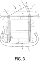
- the band-like member B is set on the attaching apparatus 1. Specifically, one end portion of the band-like member B, which is wound onto a winding core or the like disposed outside the tire T, is introduced between the inner surface of the case 8 and the outer circumferential surface of the rotary drum 3 via the guide portion 6 as exemplified in FIGS. 2 and 3 , and is disposed between the positioning plates 7.
- the band-like member B is wound around the outer circumferential surface of the rotary drum 3 with the surface of the release paper P facing the inner surface of the case 8.
- the release paper P is peeled from the band-like member B and the band-like member B is attached to the tire inner surface Ta.
- the band-like member B from which the release paper P is peeled is inserted between the tire inner surface Ta and the outer circumferential surface of the rotary drum 3, and the one end portion of the band-like member B is compression-bonded to the tire inner surface Ta by the outer circumferential surface of the rotary drum 3. In this state, setting of the attaching apparatus 1 and the band-like member B with respect to the tire T is completed.
- the traveling roller 2 is relatively moved in the circumferential direction of the tire T.
- the tire T is rotated about the tire axis CL by the drive roller 13 that is in contact with the outer surface of the tire T so as to perform rotational drive. Since the attaching apparatus 1 is fixed at a constant position by the support arm 9, when the tire T is rotated in the circumferential direction, the traveling roller 2 rolls on the tire inner surface Ta and moves relative to the tire T in the circumferential direction.
- the band-like member B wound onto the outer circumferential surface of the rotary drum 3 is sent toward the outlet 8b, and is sequentially fed from the outlet 8b to the outside of the case 8.
- the fed band-like member B is pressed by the outer circumferential surface of the rotary drum 3 and is compression-bonded and attached to the inner surface Ta of the tire.
- the band-like member B When the tire T is rotated one round, the band-like member B is attached to the entire circumference of the tire inner surface Ta. Thereafter, the band-like member B is cut at a position overlapping an end surface serving as an adhesion start point, and the band-like member B set on the attaching apparatus 1 and the band-like member B attached to the tire inner surface Ta are separated from each other. Cutting operation of the band-like member B is performed by, for example, an operator using a cutter or the like. A cutting tool for cutting the band-like member B may be provided on the attaching apparatus 1 as well.
- the band-like member B can be continuously introduced from the outside of the tire T and wound onto the outer circumferential surface of the rotary drum 3 that is rotationally driven by rotation of the traveling roller 2 rolling on the tire inner surface Ta. Since the band-like member is continuously compression-bonded to the tire inner surface Ta by the outer circumferential surface of the rotary drum 3 in rotation, it is unnecessary to cut the band-like member B by the attaching length or to wind the band-like member B for each tire T in advance. Accordingly, it is advantageous for improving the efficiency of attachment work while reducing the man-hours.
- the band-like member B Since the projection portions 3b provided on the outer circumferential surface of the rotary drum 3 bite into the wound band-like member B, the band-like member B is unlikely to be displaced with respect to the outer circumferential surface of the rotary drum 3. Accordingly, the band-like member B can be smoothly attached to the tire inner surface Ta.
- the tension of the band-like member B supplied from the outside of the tire T can be adjusted by changing the gear ratio of the rotary drive gear 4, the traveling roller gear 2b, and the transfer gear 5 used together.
- the tension By appropriately adjusting the tension, it is possible to prevent the band-like member B from being stretched or wrinkled, so that the band-like member B can be accurately attached to the tire inner surface Ta regardless of the skill of the operator.
- the band-like member B fed out from the rotary drum 3 can be positioned at an appropriate position in the tire lateral direction. Accordingly, it is advantageous for accurately attaching the band-like member B to the tire inner surface Ta.
- a plurality of rotating drums 3 are coaxially provided in parallel at an interval in the tire axial direction.
- the position of each rotary drum 3 in the tire lateral direction is adjusted and set at a desired position.
- Positioning plates 7 are disposed on both sides of each rotary drum 3.
- a plurality of band-like members B can be attached to desired positions in parallel in the width direction of the tire inner surface Ta at one time.
- Each rotary drum 3 has an appropriate width in accordance with the width of the band-like member B to be attached.
- rotating drums 3 having different outer diameters are provided coaxially in parallel at intervals in the tire axial direction.
- the position of each rotary drum 3 in the tire lateral direction is adjusted and set at a desired position.
- Positioning plates 7 are disposed on both sides of each rotary drum 3.
- a plurality of band-like members B having different thicknesses can be attached to desired positions in parallel in the width direction of the tire inner surface Ta at one time.
- Each rotary drum 3 has an appropriate width in accordance with the width of the band-like member B to be attached. In this manner, the outer diameter of at least one rotary drum 3 may differ from the outer diameter of another rotating drum 3 among the rotary drums 3.
- a method of relatively moving the attaching apparatus 1 in the circumferential direction of the tire T is not particularly limited.
- a drive unit such as a motor to the rotary drum 3 or the traveling roller 2 and rotationally driving the traveling roller 2 by the drive unit, it is also possible to relatively move the attaching apparatus 1 in the circumferential direction in a state in which the tire T is rotated while maintaining the attaching apparatus 1 in is maintained at a constant position.
- the attaching apparatus 1 can be relatively moved in the circumferential direction of the tire T.
- the case 8 is not essential, and thus can be omitted.
- a frame or the like for supporting the rotary drum 3 is provided instead of the case 8.
- Embodiments of the present invention can be used when attaching another band-like member B without being limited to a sound absorbing member.
Landscapes
- Engineering & Computer Science (AREA)
- Mechanical Engineering (AREA)
- Tyre Moulding (AREA)
- Tires In General (AREA)
Applications Claiming Priority (2)
| Application Number | Priority Date | Filing Date | Title |
|---|---|---|---|
| JP2016212443A JP6447612B2 (ja) | 2016-10-31 | 2016-10-31 | タイヤ内面への帯状部材の貼付け装置および方法 |
| PCT/JP2017/036671 WO2018079247A1 (ja) | 2016-10-31 | 2017-10-10 | タイヤ内面への帯状部材の貼付け装置および方法 |
Publications (2)
| Publication Number | Publication Date |
|---|---|
| EP3533596A1 true EP3533596A1 (de) | 2019-09-04 |
| EP3533596A4 EP3533596A4 (de) | 2020-07-01 |
Family
ID=62023488
Family Applications (1)
| Application Number | Title | Priority Date | Filing Date |
|---|---|---|---|
| EP17864610.5A Withdrawn EP3533596A4 (de) | 2016-10-31 | 2017-10-10 | Verfahren und vorrichtung zum aufkleben eines bandartigen elements auf eine reifeninnenfläche |
Country Status (5)
| Country | Link |
|---|---|
| EP (1) | EP3533596A4 (de) |
| JP (1) | JP6447612B2 (de) |
| KR (1) | KR102003672B1 (de) |
| CN (1) | CN109906143B (de) |
| WO (1) | WO2018079247A1 (de) |
Cited By (2)
| Publication number | Priority date | Publication date | Assignee | Title |
|---|---|---|---|---|
| IT202000015739A1 (it) * | 2020-06-30 | 2021-12-30 | Bridgestone Europe Nv Sa | Metodo e unita' di applicazione per applicare un materiale fonoassorbente in una cavita' interna di uno pneumatico |
| JP2023030592A (ja) * | 2021-08-23 | 2023-03-08 | 住友ゴム工業株式会社 | 吸音材貼付装置、吸音材貼付方法及びこれを含む空気入りタイヤの製造方法 |
Families Citing this family (3)
| Publication number | Priority date | Publication date | Assignee | Title |
|---|---|---|---|---|
| JP6551580B1 (ja) * | 2018-06-25 | 2019-07-31 | 横浜ゴム株式会社 | タイヤ内面への帯状部材の貼付け装置および方法 |
| IT202000015748A1 (it) * | 2020-06-30 | 2021-12-30 | Bridgestone Europe Nv Sa | Metodo e unita' di applicazione per applicare un materiale fonoassorbente in una cavita' interna di uno pneumatico |
| KR102456912B1 (ko) * | 2021-10-12 | 2022-10-21 | 금호타이어 주식회사 | 타이어 흡음재 압착장치 |
Family Cites Families (14)
| Publication number | Priority date | Publication date | Assignee | Title |
|---|---|---|---|---|
| JP3199641B2 (ja) * | 1996-08-28 | 2001-08-20 | 住友ゴム工業株式会社 | 帯状部材の貼付方法及び貼付装置 |
| JP4746421B2 (ja) | 2005-12-21 | 2011-08-10 | 住友ゴム工業株式会社 | トレッド内面への帯状スポンジ材の貼付け方法、及びその貼付け装置 |
| JP4755543B2 (ja) * | 2006-06-30 | 2011-08-24 | 住友ゴム工業株式会社 | 帯状スポンジ材の貼付け方法、及びその貼付け装置 |
| JP2008254337A (ja) * | 2007-04-05 | 2008-10-23 | Bridgestone Corp | タイヤの製造方法およびその装置 |
| JP2008254338A (ja) * | 2007-04-05 | 2008-10-23 | Bridgestone Corp | タイヤの製造方法およびその装置 |
| JP2009160762A (ja) * | 2007-12-28 | 2009-07-23 | Bridgestone Corp | タイヤ製造方法 |
| JP5052388B2 (ja) * | 2008-04-07 | 2012-10-17 | 株式会社ブリヂストン | 未加硫タイヤの製造装置及び方法 |
| KR100971729B1 (ko) * | 2008-10-20 | 2010-07-22 | 금호타이어 주식회사 | 타이어의 흡음재 부착 장치 |
| JP5353254B2 (ja) * | 2009-01-13 | 2013-11-27 | 横浜ゴム株式会社 | 未加硫タイヤの製造方法 |
| JP5808896B2 (ja) * | 2010-09-02 | 2015-11-10 | 株式会社ブリヂストン | シート状部材貼り付け用ロールおよびそれを用いたタイヤ製造装置 |
| JP5797448B2 (ja) * | 2011-05-02 | 2015-10-21 | 株式会社ブリヂストン | ローラ |
| JP5952963B2 (ja) * | 2013-05-07 | 2016-07-13 | 住友ゴム工業株式会社 | ゴムストリップ貼付け方法、それを用いた空気入りタイヤの製造方法、及び、貼付け装置 |
| JP6303456B2 (ja) * | 2013-12-03 | 2018-04-04 | 横浜ゴム株式会社 | 空気入りタイヤ及びその製造方法 |
| CN104309414B (zh) * | 2014-09-30 | 2017-02-01 | 杭州绿奇科技有限公司 | 一种防刺扎轮胎的贴片方法、贴片机及其使用方法 |
-
2016
- 2016-10-31 JP JP2016212443A patent/JP6447612B2/ja active Active
-
2017
- 2017-10-10 KR KR1020197008168A patent/KR102003672B1/ko active Active
- 2017-10-10 WO PCT/JP2017/036671 patent/WO2018079247A1/ja not_active Ceased
- 2017-10-10 EP EP17864610.5A patent/EP3533596A4/de not_active Withdrawn
- 2017-10-10 CN CN201780065149.XA patent/CN109906143B/zh not_active Expired - Fee Related
Cited By (4)
| Publication number | Priority date | Publication date | Assignee | Title |
|---|---|---|---|---|
| IT202000015739A1 (it) * | 2020-06-30 | 2021-12-30 | Bridgestone Europe Nv Sa | Metodo e unita' di applicazione per applicare un materiale fonoassorbente in una cavita' interna di uno pneumatico |
| WO2022002796A1 (en) * | 2020-06-30 | 2022-01-06 | Bridgestone Europe Nv/Sa | Method and application unit for applying a sound-absorbing material in an inner cavity of a pneumatic tyre |
| US12409624B2 (en) | 2020-06-30 | 2025-09-09 | Bridgestone Europe Nv/Sa | Method and application unit for applying a sound-absorbing material in an inner cavity of a pneumatic tire |
| JP2023030592A (ja) * | 2021-08-23 | 2023-03-08 | 住友ゴム工業株式会社 | 吸音材貼付装置、吸音材貼付方法及びこれを含む空気入りタイヤの製造方法 |
Also Published As
| Publication number | Publication date |
|---|---|
| KR102003672B1 (ko) | 2019-07-25 |
| CN109906143A (zh) | 2019-06-18 |
| CN109906143B (zh) | 2020-02-28 |
| KR20190034351A (ko) | 2019-04-01 |
| EP3533596A4 (de) | 2020-07-01 |
| JP2018069582A (ja) | 2018-05-10 |
| JP6447612B2 (ja) | 2019-01-09 |
| WO2018079247A1 (ja) | 2018-05-03 |
Similar Documents
| Publication | Publication Date | Title |
|---|---|---|
| EP3533596A1 (de) | Verfahren und vorrichtung zum aufkleben eines bandartigen elements auf eine reifeninnenfläche | |
| JP6551580B1 (ja) | タイヤ内面への帯状部材の貼付け装置および方法 | |
| TWI751342B (zh) | 保護膠帶黏貼方法以及保護膠帶黏貼裝置 | |
| JP2002535219A (ja) | ファイバ設置・巻付機用オーバーラップテープエンドエフェクタ | |
| CN1254359A (zh) | 双面胶带、双面胶带的制造方法与制造装置 | |
| JP6790587B2 (ja) | タイヤ内面への帯状部材の貼付け装置および方法 | |
| JP5508508B1 (ja) | シートの貼付装置 | |
| JP5074057B2 (ja) | 巻取方法 | |
| JP4205055B2 (ja) | タイヤ構成部材の貼着装置および貼着方法 | |
| WO2014103621A1 (ja) | ゴムストリップの貼付装置 | |
| US10215657B2 (en) | Automated balance-weight applicator | |
| JP4517979B2 (ja) | エッジワイズコイルの巻線装置 | |
| US20090151875A1 (en) | Sheet cutting table | |
| KR20120000604A (ko) | 웨이퍼 링의 테이핑 방법과 그 장치 | |
| US10518494B2 (en) | Bleeder cord affixing device and method | |
| JP7137515B2 (ja) | ロール型離型紙剥離装置 | |
| GB2147236A (en) | Label cutting machine | |
| CN112744631B (zh) | 一种薄膜分切装置及分切方法 | |
| WO2018110227A1 (ja) | テープ巻付装置 | |
| JPS63231927A (ja) | タイヤ部材の供給装置 | |
| CN221625289U (zh) | 一种医疗敷料生产用分条卷料装置 | |
| CN210734633U (zh) | 一种合成革成品检查机的连动包膜机构 | |
| JP5016082B2 (ja) | トイレットペーパーロール及びトイレットペーパーロールの製造方法 | |
| JP2013166295A (ja) | タイヤ成形用ゴム部材の貼付装置 | |
| JPH02143844A (ja) | タイヤサイドウオールへの未加硫ゴム貼着装置 |
Legal Events
| Date | Code | Title | Description |
|---|---|---|---|
| STAA | Information on the status of an ep patent application or granted ep patent |
Free format text: STATUS: THE INTERNATIONAL PUBLICATION HAS BEEN MADE |
|
| PUAI | Public reference made under article 153(3) epc to a published international application that has entered the european phase |
Free format text: ORIGINAL CODE: 0009012 |
|
| STAA | Information on the status of an ep patent application or granted ep patent |
Free format text: STATUS: REQUEST FOR EXAMINATION WAS MADE |
|
| 17P | Request for examination filed |
Effective date: 20190529 |
|
| AK | Designated contracting states |
Kind code of ref document: A1 Designated state(s): AL AT BE BG CH CY CZ DE DK EE ES FI FR GB GR HR HU IE IS IT LI LT LU LV MC MK MT NL NO PL PT RO RS SE SI SK SM TR |
|
| AX | Request for extension of the european patent |
Extension state: BA ME |
|
| DAV | Request for validation of the european patent (deleted) | ||
| DAX | Request for extension of the european patent (deleted) | ||
| A4 | Supplementary search report drawn up and despatched |
Effective date: 20200529 |
|
| RIC1 | Information provided on ipc code assigned before grant |
Ipc: B29D 30/00 20060101AFI20200525BHEP Ipc: B60C 5/00 20060101ALI20200525BHEP Ipc: B29D 30/06 20060101ALI20200525BHEP |
|
| STAA | Information on the status of an ep patent application or granted ep patent |
Free format text: STATUS: THE APPLICATION IS DEEMED TO BE WITHDRAWN |
|
| 18D | Application deemed to be withdrawn |
Effective date: 20210112 |