EP3532714B1 - High power density insulated exhaust heating system - Google Patents
High power density insulated exhaust heating system Download PDFInfo
- Publication number
- EP3532714B1 EP3532714B1 EP17711476.6A EP17711476A EP3532714B1 EP 3532714 B1 EP3532714 B1 EP 3532714B1 EP 17711476 A EP17711476 A EP 17711476A EP 3532714 B1 EP3532714 B1 EP 3532714B1
- Authority
- EP
- European Patent Office
- Prior art keywords
- heater element
- heating apparatus
- strip
- support member
- heater
- Prior art date
- Legal status (The legal status is an assumption and is not a legal conclusion. Google has not performed a legal analysis and makes no representation as to the accuracy of the status listed.)
- Active
Links
Images


Classifications
-
- F—MECHANICAL ENGINEERING; LIGHTING; HEATING; WEAPONS; BLASTING
- F01—MACHINES OR ENGINES IN GENERAL; ENGINE PLANTS IN GENERAL; STEAM ENGINES
- F01N—GAS-FLOW SILENCERS OR EXHAUST APPARATUS FOR MACHINES OR ENGINES IN GENERAL; GAS-FLOW SILENCERS OR EXHAUST APPARATUS FOR INTERNAL-COMBUSTION ENGINES
- F01N3/00—Exhaust or silencing apparatus having means for purifying, rendering innocuous, or otherwise treating exhaust
- F01N3/08—Exhaust or silencing apparatus having means for purifying, rendering innocuous, or otherwise treating exhaust for rendering innocuous
- F01N3/10—Exhaust or silencing apparatus having means for purifying, rendering innocuous, or otherwise treating exhaust for rendering innocuous by thermal or catalytic conversion of noxious components of exhaust
- F01N3/18—Exhaust or silencing apparatus having means for purifying, rendering innocuous, or otherwise treating exhaust for rendering innocuous by thermal or catalytic conversion of noxious components of exhaust characterised by methods of operation; Control
- F01N3/20—Exhaust or silencing apparatus having means for purifying, rendering innocuous, or otherwise treating exhaust for rendering innocuous by thermal or catalytic conversion of noxious components of exhaust characterised by methods of operation; Control specially adapted for catalytic conversion
- F01N3/2006—Periodically heating or cooling catalytic reactors, e.g. at cold starting or overheating
- F01N3/2013—Periodically heating or cooling catalytic reactors, e.g. at cold starting or overheating using electric or magnetic heating means
-
- F—MECHANICAL ENGINEERING; LIGHTING; HEATING; WEAPONS; BLASTING
- F01—MACHINES OR ENGINES IN GENERAL; ENGINE PLANTS IN GENERAL; STEAM ENGINES
- F01N—GAS-FLOW SILENCERS OR EXHAUST APPARATUS FOR MACHINES OR ENGINES IN GENERAL; GAS-FLOW SILENCERS OR EXHAUST APPARATUS FOR INTERNAL-COMBUSTION ENGINES
- F01N3/00—Exhaust or silencing apparatus having means for purifying, rendering innocuous, or otherwise treating exhaust
- F01N3/02—Exhaust or silencing apparatus having means for purifying, rendering innocuous, or otherwise treating exhaust for cooling, or for removing solid constituents of, exhaust
- F01N3/021—Exhaust or silencing apparatus having means for purifying, rendering innocuous, or otherwise treating exhaust for cooling, or for removing solid constituents of, exhaust by means of filters
- F01N3/023—Exhaust or silencing apparatus having means for purifying, rendering innocuous, or otherwise treating exhaust for cooling, or for removing solid constituents of, exhaust by means of filters using means for regenerating the filters, e.g. by burning trapped particles
- F01N3/027—Exhaust or silencing apparatus having means for purifying, rendering innocuous, or otherwise treating exhaust for cooling, or for removing solid constituents of, exhaust by means of filters using means for regenerating the filters, e.g. by burning trapped particles using electric or magnetic heating means
-
- F—MECHANICAL ENGINEERING; LIGHTING; HEATING; WEAPONS; BLASTING
- F23—COMBUSTION APPARATUS; COMBUSTION PROCESSES
- F23G—CREMATION FURNACES; CONSUMING WASTE PRODUCTS BY COMBUSTION
- F23G7/00—Incinerators or other apparatus for consuming industrial waste, e.g. chemicals
-
- H—ELECTRICITY
- H05—ELECTRIC TECHNIQUES NOT OTHERWISE PROVIDED FOR
- H05B—ELECTRIC HEATING; ELECTRIC LIGHT SOURCES NOT OTHERWISE PROVIDED FOR; CIRCUIT ARRANGEMENTS FOR ELECTRIC LIGHT SOURCES, IN GENERAL
- H05B3/00—Ohmic-resistance heating
-
- H—ELECTRICITY
- H05—ELECTRIC TECHNIQUES NOT OTHERWISE PROVIDED FOR
- H05B—ELECTRIC HEATING; ELECTRIC LIGHT SOURCES NOT OTHERWISE PROVIDED FOR; CIRCUIT ARRANGEMENTS FOR ELECTRIC LIGHT SOURCES, IN GENERAL
- H05B3/00—Ohmic-resistance heating
- H05B3/02—Details
-
- H—ELECTRICITY
- H05—ELECTRIC TECHNIQUES NOT OTHERWISE PROVIDED FOR
- H05B—ELECTRIC HEATING; ELECTRIC LIGHT SOURCES NOT OTHERWISE PROVIDED FOR; CIRCUIT ARRANGEMENTS FOR ELECTRIC LIGHT SOURCES, IN GENERAL
- H05B3/00—Ohmic-resistance heating
- H05B3/02—Details
- H05B3/06—Heater elements structurally combined with coupling elements or holders
-
- H—ELECTRICITY
- H05—ELECTRIC TECHNIQUES NOT OTHERWISE PROVIDED FOR
- H05B—ELECTRIC HEATING; ELECTRIC LIGHT SOURCES NOT OTHERWISE PROVIDED FOR; CIRCUIT ARRANGEMENTS FOR ELECTRIC LIGHT SOURCES, IN GENERAL
- H05B3/00—Ohmic-resistance heating
- H05B3/40—Heating elements having the shape of rods or tubes
- H05B3/42—Heating elements having the shape of rods or tubes non-flexible
- H05B3/48—Heating elements having the shape of rods or tubes non-flexible heating conductor embedded in insulating material
-
- F—MECHANICAL ENGINEERING; LIGHTING; HEATING; WEAPONS; BLASTING
- F01—MACHINES OR ENGINES IN GENERAL; ENGINE PLANTS IN GENERAL; STEAM ENGINES
- F01N—GAS-FLOW SILENCERS OR EXHAUST APPARATUS FOR MACHINES OR ENGINES IN GENERAL; GAS-FLOW SILENCERS OR EXHAUST APPARATUS FOR INTERNAL-COMBUSTION ENGINES
- F01N2240/00—Combination or association of two or more different exhaust treating devices, or of at least one such device with an auxiliary device, not covered by indexing codes F01N2230/00 or F01N2250/00, one of the devices being
- F01N2240/16—Combination or association of two or more different exhaust treating devices, or of at least one such device with an auxiliary device, not covered by indexing codes F01N2230/00 or F01N2250/00, one of the devices being an electric heater, i.e. a resistance heater
-
- F—MECHANICAL ENGINEERING; LIGHTING; HEATING; WEAPONS; BLASTING
- F01—MACHINES OR ENGINES IN GENERAL; ENGINE PLANTS IN GENERAL; STEAM ENGINES
- F01N—GAS-FLOW SILENCERS OR EXHAUST APPARATUS FOR MACHINES OR ENGINES IN GENERAL; GAS-FLOW SILENCERS OR EXHAUST APPARATUS FOR INTERNAL-COMBUSTION ENGINES
- F01N2450/00—Methods or apparatus for fitting, inserting or repairing different elements
- F01N2450/22—Methods or apparatus for fitting, inserting or repairing different elements by welding or brazing
-
- H—ELECTRICITY
- H05—ELECTRIC TECHNIQUES NOT OTHERWISE PROVIDED FOR
- H05B—ELECTRIC HEATING; ELECTRIC LIGHT SOURCES NOT OTHERWISE PROVIDED FOR; CIRCUIT ARRANGEMENTS FOR ELECTRIC LIGHT SOURCES, IN GENERAL
- H05B2203/00—Aspects relating to Ohmic resistive heating covered by group H05B3/00
- H05B2203/014—Heaters using resistive wires or cables not provided for in H05B3/54
-
- H—ELECTRICITY
- H05—ELECTRIC TECHNIQUES NOT OTHERWISE PROVIDED FOR
- H05B—ELECTRIC HEATING; ELECTRIC LIGHT SOURCES NOT OTHERWISE PROVIDED FOR; CIRCUIT ARRANGEMENTS FOR ELECTRIC LIGHT SOURCES, IN GENERAL
- H05B2203/00—Aspects relating to Ohmic resistive heating covered by group H05B3/00
- H05B2203/022—Heaters specially adapted for heating gaseous material
-
- Y—GENERAL TAGGING OF NEW TECHNOLOGICAL DEVELOPMENTS; GENERAL TAGGING OF CROSS-SECTIONAL TECHNOLOGIES SPANNING OVER SEVERAL SECTIONS OF THE IPC; TECHNICAL SUBJECTS COVERED BY FORMER USPC CROSS-REFERENCE ART COLLECTIONS [XRACs] AND DIGESTS
- Y02—TECHNOLOGIES OR APPLICATIONS FOR MITIGATION OR ADAPTATION AGAINST CLIMATE CHANGE
- Y02T—CLIMATE CHANGE MITIGATION TECHNOLOGIES RELATED TO TRANSPORTATION
- Y02T10/00—Road transport of goods or passengers
- Y02T10/10—Internal combustion engine [ICE] based vehicles
- Y02T10/12—Improving ICE efficiencies
Definitions
- the present disclosure relates to exhaust systems for internal combustion engines, and more specifically to exhaust gas heating apparatuses installed in the exhaust systems.
- Heater systems are used in exhaust systems that are coupled to an internal combustion engine in order to assist in the reduction of the undesirable release of various gases and other pollutant emissions into the atmosphere.
- These exhaust systems typically include various after-treatment devices, such as diesel particulate filters (DPF); a catalytic converter; selective catalytic reducers (SCR) that capture carbon monoxide (CO), nitrogen oxides (NO x ), particulate matters (PMs), and unburned hydrocarbons (HCs) contained in the exhaust gas; a diesel oxidation catalyst (DOC); a lean NO x trap (LNT); an ammonia slip catalyst; or reformers, among others.
- DPF diesel particulate filters
- SCR selective catalytic reducers
- CO carbon monoxide
- NO x nitrogen oxides
- PMs particulate matters
- HCs unburned hydrocarbons
- DOC diesel oxidation catalyst
- LNT lean NO x trap
- ammonia slip catalyst or reformers, among others.
- the heaters may be activated periodically or at a predetermined time to increase the exhaust temperature and activate the catalysts and/or to burn the particulate matters or unburned hydrocarbons that have been captured in the exhaust system.
- Heating apparatuses have been disclosed in DE-202015103787U1 , DE-19943846 , JP-H0559939 , US-5672324 , US-2012/097659 .
- the electric heaters are generally installed in exhaust pipes or components such as containers of the exhaust system and are subjected to harsh environmental conditions, such as vibration, mechanical shock, temperature cycling, high heat, etc.
- the invention relates to a heating apparatus for a fluid flow system having a fluid conduit according to independent claim 1.
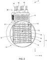
- the heating apparatus 1 generally includes a junction box 5, a perforated box assembly 10, a container body 14 including one or more separable container section components 15, and a heater flange component 20.
- Exhaust system coupling components 25 may be provided at opposing ends of the container body 14 to couple the heating apparatus 1 into an exhaust system (not shown).
- the flow of exhaust gases passes from the exhaust system into the heating apparatus 1 through an exhaust gas channel 29 formed in the heating apparatus 1.
- the exhaust gas channel 29 is defined jointly by the container body 14 and the heater flange component 20 and extends along an exhaust flow direction Z of the container body 14.
- the heater flange component 20 generally has a plate configuration in one form and may include a plurality of tabs 22 that are inserted into corresponding slots (not shown) in the container body 14.
- the modular design of the heating apparatus 1 allows the dimensions of the various components in the heating apparatus 1 to stay the same with only the length of each component being varied to accommodate the requirement(s) of the application.
- a junction box lid 7 may be incorporated into the heating apparatus 1.
- the container body 14 and the heater flange component 20 may be configured to fit inside an exhaust pipe (not shown) such that the container body 14 is disposed in an exhaust gas channel defined by the exhaust pipe.
- junction box 5 and the perforated box assembly 10 are merely exemplary and should not be construed as limiting the scope of the present disclosure.
- the heating apparatus 1 includes one or more heater elements 12 and a support member 16.
- the heater elements 12 may be disposed to be in a direction across the exhaust flow direction Z.
- the heater elements 12 may be a plurality of cartridge heaters extending along a vertical direction Y, perpendicular to the exhaust flow direction Z.
- the heater elements 12 may be disposed to be at an angle relative to the exhaust flow direction Z.
- the junction box 5 and the junction box lid 7 are removed to show proximal ends 30 and the power pins 40 of the heater elements 12.
- the heater elements 12 may be cartridge heaters, each including a resistive heating element 22 in the form of a metal wire, a core 28 around which the resistive heating element 22 is wound, an outer sheath 60 surrounding the core 28, and an insulating material 64.
- the core 28 may be a ceramic core defining two longitudinal bores 34, 36 in which a pair of power pins 40 inserted. A first end 50 of the resistive heating element 22 is electrically connected to one of the power pins 40 and the other end 52 of the resistive heating element 22 is electrically connected to the other one of the power pins 40.
- the outer sheath 60 may have an open end and a closed end, or two open ends, thus creating an annular space between the outer sheath 60 and the resistive heating element 22.
- the insulating material 64 fills in the annular space and may be any material that can provide electrical isolation between the resistive heating element 22 and the outer sheath 60.
- the insulating material 64 may be magnesium oxide (MgO) or the like and is poured into the open end of the sheath 60 to fill the annular space between the resistive heating element 22 and the inner surface of the sheath 60.
- the open end of the sheath 60 may be sealed, for example by using a potting compound and/or discrete sealing members 62.
- the entire assembly is then compacted or compressed, as by swaging or by other suitable processes, to reduce the diameter of the outer sheath 60 and to thus compact and compress the MgO and to at least partially crush the ceramic core 28 so as to collapse the core 28 about the power pins 40 to ensure good electrical contact and thermal transfer.
- the compacted MgO provides a relatively good heat transfer path between the resistive heating element 22 and the outer sheath 60 and it also electrically insulates the outer sheath 60 from the resistive heating element 22.
- the heater element 12 defines a proximal end 30 where the sealing member 62 is disposed and the power pins 40 protrudes outwardly, and a distal end 32 opposing the proximal end 30.
- the support member 16 includes a plurality of support sheets 18 parallel to one another and extending along a horizontal direction X perpendicular to the exhaust flow direction Z and the vertical direction Y to support the plurality of the heater elements 12 in the container body 14.
- the plurality of support sheets 18 may be spaced apart along the vertical direction Y at a spacing less than 7.62 cm (3 inches).
- the support member 16 further includes at least one cross member 19 extending in a vertical direction Y for connecting the support sheets 18.
- the support sheets 18 and the cross member 19 may be formed as an integral, one-piece component, or may be formed separately and later connected together.
- the support member 16 may include only one support sheet 18 to support the heating elements 12 inside the exhaust gas channel 29 while distributing the heat generated by the heater elements 12 to the exhaust gas flowing in the exhaust gas channel 29.
- the support member 16 may provide a combination of conductive, convective and radiative heat transfer to improve heat transfer from the heater elements 12 to the surrounding exhaust gas, thereby obtaining, without increasing the temperature of the heater, a higher power density than that obtained by a heater element without the support member 16.
- Power density is determined by dividing the power by the surface area.
- the surface area may be the sheath surface area or the resistive wire surface area.
- the maximum power density of the heater to avoid overheating is also affected by velocity of the exhaust gas, which, in turn, is affected by the engine speeds and the engine loads. When the velocity of the exhaust gas is higher, more heat from the heater element may be carried away by the exhaust gas per unit of time. Therefore, the heater element may generate a higher power density when the velocity of the exhaust gas is relatively high without overheating or damaging the heater element.
- the power density of the heater element may be limited when an engine is running at a lower engine speed and at lower engine load.
- the velocity of the exhaust gas flow is relatively low due to lower engine speed and lower engine load, less heat is carried away by the exhaust gas per unit of time.
- the heater element heats up faster, and thus a lower watt density is used in order to avoid over-heating.
- the durability of a heater element of a cartridge type, a cable type, or a tubular type depends, in part, on the temperature of the resistive heating element and the outer sheath. Therefore, the heater element should be configured based on the engine speed and the engine torque in order to properly heat the exhaust gas without compromising durability of the heater element.
- the mass flow could be about 0.04kg/s, and the exhaust temperature approximately 150°C.
- a typical single element heater in these exhaust conditions may allow a maximum power density of approximately 50 watts/in 2 for the sheath and approximately 120 watts/in 2 for the resistive heating wire in order to avoid damage to the heater.
- the heating apparatus including the heater element and the support member according to the present disclosure may allow a maximum power density of approximately 84 watts/in 2 for the sheath and approximately 230 watts/in 2 for the resistance wire and result in the same heater temperature and durability. Therefore, the heating apparatus enable higher power density than that of a typical heater element.
- the support member of the heating apparatus of the prior art not only stiffens or restricts the movement of the insulated heater element, but also improves heat transfer from the heater element to the surrounding exhaust gas. Therefore, the power density of the heating apparatus can be increased without increasing the target heating temperature of the heater element.
- the heater elements 12 may be securely disposed inside the the exhaust gas channel 29, for example, by perforated box assembly 10 and/or other mounting structure provided at the proximal ends 32 of the heater elements 12. In this case, restricting movement of the heater element 12 by a support member may not be necessary. Therefore, the heating apparatus 1 may include one or more fins attached to the heater element 12 for the sole purpose of providing conductive, convective and radiative heat transfer to improve heat transfer from the heater element 12 to the surrounding exhaust gas. The fins may be configured to be structurally similar to the support sheets 18 as shown in FIG. 2 , but are not used to support the heater elements 12.
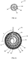
- a heating apparatus 70 includes a heater element 72 and a support member 74.
- the heater element 72 is a cable heater and bent into a shape selected from a group consisting of a spiral shape, a sinuated shape, a coil shape, a tortuous shape, a zig-zag shape or any of the combinations thereof.
- the support member 74 may include a corrugated strip 74 and a peripheral wall 76 surrounding the corrugated strip 74.
- the corrugated strip 74 is bent into a spiral shape conforming to the spiral shape of the heater element 72 such that heater element 72 may be sandwiched between portions of the corrugated strip 74.
- the heater element 72 includes a plurality of sections arranged along a radial direction of the peripheral wall 76 which has a tubular shape and which defines a hollow space.
- the corrugated strip 74 incudes a plurality of sections disposed between adjacent two of the sections of the heater element 72 and between an outermost section of the heater element 72 and the peripheral wall 76.
- the corrugated strip 74 may be wrapped back to have some overlap portions A. Shapes other than the spiral shape may also be employed, such as by way of example, sinuated bends (not shown) while remaining within the scope of the present disclosure.
- the corrugated strip 74 includes alternate ridges 80 and grooves 82.
- the corrugated strip 74 may be brazed or welded to the heater element 72 at a plurality of contact points to increase stiffness of the heater element 72.
- the plurality of contact points are spaced at a spacing along a length of the corrugated strip 74. The spacing is less than ten times an outerside diameter of the heater element 72.
- the natural frequency of vibration for the sections of the heater element between adjacent two contact points may be greater than 400 Hz.
- the heater transfer characteristics are optimized but it is relatively difficult to secure the heater element 72 to the corrugated strip 74.
- the number of the contact points is selected such that a temperature variation across the heating apparatus is less than 200°C.
- the heater element 72 may be disposed loosely between portions of the corrugated strip 74, or not even contact the heater element 72.
- the corrugated strip 74 acts as both a stiffener and a vibration dampener.
- the outer wall 72 may be a part of the container body 14 or a separate component from the container body 14 and completely disposed in the exhaust gas channel.
- the corrugated strip 74 provides a combination of conductive, convective and radiative heat transfer that improves heater transfer from the heater element 72 to the surrounding exhaust gas, thereby achieving a higher power density without increasing the temperature of the heater element than that provided by a typical heater element.
- the heater element 72 may be a cable heater including a resistive heating element 84, an outer sheath 86, and an insulating material 88 filling in a space between the resistive heating element 84 and the outer sheath 86. It is understood that the heater element 72 may be a cartridge heater, a tubular heater, or any heater that can be bent into a desired shape.
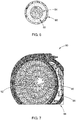
- FIG. 7 another form of a heating apparatus 90 is shown to include a heater element 92 and a support member 94.
- the support member 94 includes a corrugated sheet 96 wrapped into a spiral shape, and an outer peripheral wall 98 surrounding the corrugated sheet 96.
- the corrugated sheet 96 may be bent into a spiral shape conforming to the spiral shape of the heater element 92 so that the heater element 92 is sandwiched between portions of the corrugated sheet 94.
- the use of a junction box and perforated box assembly is eliminated and thus a simpler and lower cost assembly is provided.
- the heating apparatus 100 includes a heater element 102 and a support member 104, which may be welded or brazed for joining.
- the support member 104 includes a corrugated strip 106 and an outer peripheral wall 108. Similar to the corrugated strip 74 of FIG. 5 , the corrugated strip 106 is bent into a spiral shape conforming to the spiral shape of the heater element 102 and includes a plurality of ridges 110 and grooves 112. The outermost portion of the corrugated strip 106 is welded to an inner surface of the outer peripheral wall 108 at the ridges 110.
- the outer peripheral wall 108 may be a part of the container body 14 and defines the exhaust gas channel 29 or may be component separate from the container body 14. The outer peripheral wall 108 may be loosely disposed inside the container body 14 or fixed to the container body 14.
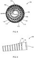
- the corrugated strip 106 is shown to be in an original, unbent state.
- the corrugated strip 106 further defines a plurality of indentations 114 at the ridges 110 and grooves 112 to facilitate engagement between the heater element 102 and the corrugated strip 106. Portions of the heater element 102 corresponding to the indentations 114 may be inserted into the indentations 114 to improve engagement between the heater element 102 and the corrugated strip 106.
- one row of indentations 114 is illustrated, it should be understood that multiple rows of indentations may be employed while remaining within the scope of the present disclosure.
- the outer peripheral wall 108 may define a mounting feature for mounting the corrugated strip 106 onto the outer peripheral wall 108.
- the mounting feature may be a plurality of annular grooves 118 formed on an inner surface of the outer peripheral wall 108 to facilitate engagement between the corrugated strip 106 and the outer peripheral wall 108. It is understood that the mounting feature is not limited to the annular grooves 118 shown in FIGS. 10 and 11 , and may be any structure that can engage and secure the corrugated strip 106 to the outer peripheral wall 108.
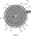
- FIG. 12 another form of a heating apparatus 120 constructed in accordance with the teachings of the present disclosure is structurally similar to that of FIG. 5 except that the heating apparatus 120 has a smaller size to fit in any part of the after-treatment container or component to heat the exhaust gas, while generating the same amount or close to the amount of heat generated by a larger size of the heating apparatus.
- the heating apparatus 120 includes a heater element 122, and a support member 124.
- the support member 124 which may be a single component or an assembly of pieces, includes a corrugated strip 126, and a peripheral wall 128 surrounding the corrugated strip 126.
- the support member 124 defines a tortuous geometry and in one form flanks opposed sides of the heater element 122 along a majority of a length of the heater element 122 as shown.
- the term "tortuous” should be construed to mean a shape that changes direction a plurality of times, in a regular or irregular manner, in order to increase heat transfer from the heater element 122 to the fluid flow, e.g. exhaust flow.
- the heater element 122 is formed into a shape selected from a group consisting of a spiral shape, a sinuated shape, a coil shape, a zig-zag shape or any of the combinations thereof. To increase the total amount of heat generated by the small-size heating apparatus 120, the heater element 122 is formed into more turns and is more compact.
- the corrugated strip 126 can be formed into more turns and includes alternate ridges 130 and grooves 132 to form a tortuous geometry.
- the corrugated strip 126 may be brazed, welded, or secured by any means to the heater element 122 at the alternate ridges 130 and grooves 132.
- the corrugated strip 126 may be configured to form a wavy surface 134 between adjacent ridges 130 and grooves 132, and/or the ridges 130 and the grooves 132 may be configured to have a wider contact area with the adjacent sections of the heater element 122. As a result, the total surface area of the corrugated strip 126 may be further increased to increase the heat transfer from the heater element 122 to the surrounding exhaust gas.
- the heating apparatus 120 may further include one or more spacers 136 and an end piece 138.
- the spacer 136 may be used to fill any gap that may be present between the peripheral wall 128 and the outermost section of the corrugated strip 126 to more tightly secure the corrugated strip 126 inside the peripheral wall 128.
- the end piece 138 is disposed at an end of the heater element 122 so that the end of the corrugated strip 126 disposed proximate the center of the outer may be secured to the end piece 138.
- the heating apparatus has the advantages of providing more power in a smaller area, thereby reducing the size and weight of the heating apparatus without compromising heater durability.
- the heating apparatus can provide a relatively faster heat-up during engine cold start and during transient conditions.
- the supports as described herein may be arranged in order to block what is known as a "view factor," or a line of sight between parts that could radiate heat to each other.
- the supports may be arranged to block a direct line of sight between heating elements or portions of the same heating element to create a line of sight to a cooler support.
Landscapes
- Engineering & Computer Science (AREA)
- Chemical & Material Sciences (AREA)
- Mechanical Engineering (AREA)
- General Engineering & Computer Science (AREA)
- Chemical Kinetics & Catalysis (AREA)
- Combustion & Propulsion (AREA)
- Health & Medical Sciences (AREA)
- Toxicology (AREA)
- Environmental & Geological Engineering (AREA)
- Exhaust Gas After Treatment (AREA)
- Resistance Heating (AREA)
Applications Claiming Priority (2)
| Application Number | Priority Date | Filing Date | Title |
|---|---|---|---|
| US201662415042P | 2016-10-31 | 2016-10-31 | |
| PCT/US2017/020530 WO2018080578A1 (en) | 2016-10-31 | 2017-03-02 | High power density insulated exhaust heating system |
Publications (2)
| Publication Number | Publication Date |
|---|---|
| EP3532714A1 EP3532714A1 (en) | 2019-09-04 |
| EP3532714B1 true EP3532714B1 (en) | 2020-11-25 |
Family
ID=58347965
Family Applications (1)
| Application Number | Title | Priority Date | Filing Date |
|---|---|---|---|
| EP17711476.6A Active EP3532714B1 (en) | 2016-10-31 | 2017-03-02 | High power density insulated exhaust heating system |
Country Status (7)
| Country | Link |
|---|---|
| US (7) | US10598064B2 (enExample) |
| EP (1) | EP3532714B1 (enExample) |
| JP (3) | JP7077315B2 (enExample) |
| CN (2) | CN110139972B (enExample) |
| CA (1) | CA3042226C (enExample) |
| MX (6) | MX2019005020A (enExample) |
| WO (1) | WO2018080578A1 (enExample) |
Cited By (1)
| Publication number | Priority date | Publication date | Assignee | Title |
|---|---|---|---|---|
| US12049839B2 (en) | 2020-12-09 | 2024-07-30 | Purem GmbH | Exhaust gas heating unit |
Families Citing this family (21)
| Publication number | Priority date | Publication date | Assignee | Title |
|---|---|---|---|---|
| US11268415B2 (en) * | 2017-06-02 | 2022-03-08 | Volvo Truck Corporation | Method for controlling the temperature of a NOx controlling component and an exhaust after treatment system |
| US11261776B2 (en) * | 2018-03-29 | 2022-03-01 | Emissol Llc | Methods and devices for controlling urea mixers to reduce NOx emission from combustion engines |
| GB2604235B (en) * | 2018-11-06 | 2023-01-04 | Cummins Emission Solutions Inc | Systems and Methods for Reducing Reductant Deposit Formation in a Decomposition Reactor of an Exhaust Gas Aftertreatment System for an internal combustion eng |
| DE102019101679A1 (de) * | 2019-01-24 | 2020-07-30 | Eberspächer Exhaust Technology GmbH & Co. KG | Abgasheizelement |
| DE102019107384A1 (de) * | 2019-03-22 | 2020-09-24 | Eberspächer Exhaust Technology GmbH & Co. KG | Abgasheizelement |
| US10961887B2 (en) * | 2019-07-03 | 2021-03-30 | Deere & Company | Integrated reductant mixer and heater apparatus for exhaust treatment systems |
| DE102019129322A1 (de) * | 2019-10-30 | 2021-05-06 | Faurecia Emissions Control Technologies, Germany Gmbh | Elektrische Gasströmungsheizung und Fahrzeug |
| DE102020121414A1 (de) * | 2020-08-14 | 2022-02-17 | Purem GmbH | Abgasheizanordnung |
| DE202020104976U1 (de) * | 2020-08-28 | 2020-10-06 | Hjs Emission Technology Gmbh & Co. Kg | Elektrisches Heizaggregat zum Einschalten in den Abgasstrang einer Brennkraftmaschine sowie damit ausgerüstetes Abgasreinigungsaggregat |
| FR3119418A1 (fr) * | 2021-02-04 | 2022-08-05 | Faurecia Systemes D'echappement | Dispositif de chauffage pour gaz d’échappement |
| DE102021103283A1 (de) | 2021-02-11 | 2022-08-11 | Benteler Automobiltechnik Gmbh | Halter für eine elektrische Heizscheibe in eine Abgasnachbehandlungsvorrichtung |
| EP4060169B1 (de) * | 2021-03-15 | 2024-04-03 | Purem GmbH | Abgasheizer |
| DE102021202901B4 (de) * | 2021-03-24 | 2022-10-27 | Vitesco Technologies GmbH | Vorrichtung zur Abgasnachbehandlung und Verfahren zum Herstellen dieser |
| EP4098853A1 (en) * | 2021-06-01 | 2022-12-07 | Volvo Truck Corporation | An exhaust aftertreatment system |
| FR3125846A1 (fr) * | 2021-08-02 | 2023-02-03 | Faurecia Systemes D'echappement | Dispositif de chauffage électrique pour ligne d’échappement |
| DE102021122083A1 (de) * | 2021-08-26 | 2023-03-02 | Purem GmbH | Abgasheizer |
| DE102021122085A1 (de) * | 2021-08-26 | 2023-03-02 | Purem GmbH | Abgasheizer |
| FR3128485A1 (fr) * | 2021-10-25 | 2023-04-28 | Faurecia Systemes D'echappement | Elément chauffant pour ligne d’échappement |
| CN115134953A (zh) * | 2022-06-20 | 2022-09-30 | 无锡威孚力达催化净化器有限责任公司 | 一种电加热器 |
| EP4455463B1 (en) * | 2023-04-24 | 2025-12-03 | Hidria d.o.o. | Heating device |
| CN116576468A (zh) * | 2023-05-19 | 2023-08-11 | 中冶焦耐(大连)工程技术有限公司 | 一种污泥干化焚烧处理设备 |
Citations (2)
| Publication number | Priority date | Publication date | Assignee | Title |
|---|---|---|---|---|
| JPH0559939A (ja) * | 1991-06-19 | 1993-03-09 | Ngk Spark Plug Co Ltd | ヒータ付き触媒式排気浄化装置 |
| DE202015103787U1 (de) * | 2015-07-17 | 2015-08-06 | Türk & Hillinger GmbH | Gaskanal mit beheizter poröser Metallstruktur |
Family Cites Families (37)
| Publication number | Priority date | Publication date | Assignee | Title |
|---|---|---|---|---|
| US2831951A (en) | 1954-07-06 | 1958-04-22 | Watlow Electric Mfg | Cartridge heater and method of making same |
| US3970822A (en) | 1975-03-17 | 1976-07-20 | Watlow Electric Manufacturing Company | Electric cartridge heater |
| JPS6053165B2 (ja) * | 1981-03-16 | 1985-11-25 | 株式会社豊田中央研究所 | 内燃機関排気吐煙の捕集装置 |
| US4505107A (en) * | 1981-10-26 | 1985-03-19 | Nippondenso Co., Ltd. | Exhaust gas cleaning apparatus |
| US4588423A (en) * | 1982-06-30 | 1986-05-13 | Donaldson Company, Inc. | Electrostatic separator |
| KR920009120B1 (ko) * | 1988-07-06 | 1992-10-13 | 우스이 고꾸사이 산교 가부시끼가이샤 | 배기가스 정화용 촉매를 담지하기 위한 금속제 담지모체(擔持母體) |
| JPH02172538A (ja) * | 1988-12-23 | 1990-07-04 | Matsushita Electric Ind Co Ltd | 排気ガス浄化触媒体 |
| US5101095A (en) * | 1989-03-30 | 1992-03-31 | Donaldson Company, Inc. | Diesel engine gas filter with electrical heater |
| JP2512594Y2 (ja) * | 1989-04-18 | 1996-10-02 | 株式会社キクチ | ラインヒ―タ― |
| JPH03104023U (enExample) * | 1990-02-07 | 1991-10-29 | ||
| DE59107491D1 (de) * | 1990-03-19 | 1996-04-04 | Emitec Emissionstechnologie | Katalysator mit mindestens einem Temperaturfühler |
| JPH04370360A (ja) * | 1991-06-17 | 1992-12-22 | Ngk Spark Plug Co Ltd | 温度センサー付フィンヒーター |
| DE4129893A1 (de) * | 1991-09-09 | 1993-03-11 | Emitec Emissionstechnologie | Anordnung zur temperaturmessung und/oder heizung und deren verwendung in einem wabenkoerper, insbesondere katalysator-traegerkoerper |
| DE4132439A1 (de) * | 1991-09-28 | 1993-04-01 | Behr Gmbh & Co | Abgaskatalysator |
| US5409669A (en) * | 1993-01-25 | 1995-04-25 | Minnesota Mining And Manufacturing Company | Electrically regenerable diesel particulate filter cartridge and filter |
| JPH08103664A (ja) * | 1994-10-04 | 1996-04-23 | Nippondenso Co Ltd | ハニカム体およびこのハニカム体よりなる触媒担体を有する触媒コンバータ |
| JP2701192B2 (ja) * | 1993-04-23 | 1998-01-21 | 坂口電熱株式会社 | シーズヒータ及びその製造方法 |
| JP3277655B2 (ja) * | 1993-12-21 | 2002-04-22 | トヨタ自動車株式会社 | 電気加熱式触媒装置 |
| JPH08131848A (ja) * | 1994-11-15 | 1996-05-28 | Toyo Radiator Co Ltd | 排気ガス浄化用触媒担持体 |
| JP2903103B2 (ja) * | 1995-01-13 | 1999-06-07 | 株式会社デンソー | 排気ガス浄化装置 |
| JPH08218846A (ja) * | 1995-02-17 | 1996-08-27 | Nippon Soken Inc | 内燃機関の排気浄化装置用電気ヒータ |
| DE19943846A1 (de) * | 1999-09-13 | 2001-03-15 | Emitec Emissionstechnologie | Vorrichtung mit Heizelement zur Abgasreinigung |
| US6540816B2 (en) * | 2001-08-23 | 2003-04-01 | Fleetguard, Inc. | Regenerable filter with localized and efficient heating |
| US20060177358A1 (en) * | 2005-02-07 | 2006-08-10 | Tzong-Yih Lee | Active catalytic converter |
| CN100436635C (zh) * | 2006-03-24 | 2008-11-26 | 江苏常发制冷股份有限公司 | 吹胀式铝板的连续退火方法 |
| US8409516B2 (en) * | 2007-09-18 | 2013-04-02 | Amo Co., Ltd. | Monolith, catalyst convertor for purifying exhaust gas using the same and method for manufacturing the catalyst convertor |
| DE102009018182A1 (de) * | 2009-04-22 | 2010-10-28 | Emitec Gesellschaft Für Emissionstechnologie Mbh | Mehrstufig beheizbarer Wabenkörper |
| JP5624865B2 (ja) * | 2010-12-06 | 2014-11-12 | 日本特殊陶業株式会社 | 排気ガス加熱装置 |
| EP2717649B1 (en) * | 2012-03-22 | 2016-07-27 | NGK Insulators, Ltd. | Heater |
| JP6240682B2 (ja) * | 2012-12-18 | 2017-11-29 | ワトロー エレクトリック マニュファクチュアリング カンパニー | 改良排気ガス加熱装置 |
| DE102014115923A1 (de) * | 2014-10-31 | 2016-05-04 | Continental Automotive Gmbh | Wabenkörper mit elektrischer Heizvorrichtung |
| DE102015111689C5 (de) * | 2015-07-17 | 2022-09-01 | Türk & Hillinger GmbH | Elektrisch beheizbarer Katalysator und Verfahren zu dessen Herstellung |
| DE102019107384A1 (de) * | 2019-03-22 | 2020-09-24 | Eberspächer Exhaust Technology GmbH & Co. KG | Abgasheizelement |
| DE102019121382A1 (de) * | 2019-08-07 | 2021-02-11 | Faurecia Emissions Control Technologies, Germany Gmbh | Abgasbehandlungseinrichtung und Fahrzeug |
| DE102020123376A1 (de) * | 2020-09-08 | 2022-03-10 | Purem GmbH | Abgasheizer |
| US11988127B2 (en) * | 2020-10-26 | 2024-05-21 | Advanced Technology Emission Solutions Inc. | Gas flow treatment unit with turbulence generation |
| DE102020132800A1 (de) * | 2020-12-09 | 2022-06-09 | Purem GmbH | Abgasheizeinheit |
-
2017
- 2017-03-02 MX MX2019005020A patent/MX2019005020A/es unknown
- 2017-03-02 JP JP2019522958A patent/JP7077315B2/ja active Active
- 2017-03-02 CN CN201780067828.0A patent/CN110139972B/zh active Active
- 2017-03-02 CN CN202111238268.5A patent/CN113958391B/zh active Active
- 2017-03-02 US US15/448,200 patent/US10598064B2/en active Active
- 2017-03-02 CA CA3042226A patent/CA3042226C/en active Active
- 2017-03-02 EP EP17711476.6A patent/EP3532714B1/en active Active
- 2017-03-02 WO PCT/US2017/020530 patent/WO2018080578A1/en not_active Ceased
-
2019
- 2019-04-29 MX MX2024008106A patent/MX2024008106A/es unknown
- 2019-04-29 MX MX2022012731A patent/MX2022012731A/es unknown
- 2019-04-29 MX MX2022012734A patent/MX2022012734A/es unknown
- 2019-04-29 MX MX2022012732A patent/MX2022012732A/es unknown
- 2019-04-29 MX MX2022012733A patent/MX2022012733A/es unknown
-
2020
- 2020-03-02 US US16/806,175 patent/US11131227B2/en active Active
-
2021
- 2021-08-25 US US17/411,352 patent/US11408314B2/en active Active
- 2021-11-24 US US17/535,096 patent/US11585252B2/en active Active
-
2022
- 2022-05-18 JP JP2022081371A patent/JP2022116090A/ja active Pending
- 2022-05-18 JP JP2022081372A patent/JP7395648B2/ja active Active
- 2022-07-26 US US17/873,224 patent/US11686232B2/en active Active
- 2022-07-26 US US17/873,227 patent/US11913365B2/en active Active
-
2024
- 2024-01-19 US US18/417,448 patent/US12286917B2/en active Active
Patent Citations (2)
| Publication number | Priority date | Publication date | Assignee | Title |
|---|---|---|---|---|
| JPH0559939A (ja) * | 1991-06-19 | 1993-03-09 | Ngk Spark Plug Co Ltd | ヒータ付き触媒式排気浄化装置 |
| DE202015103787U1 (de) * | 2015-07-17 | 2015-08-06 | Türk & Hillinger GmbH | Gaskanal mit beheizter poröser Metallstruktur |
Cited By (1)
| Publication number | Priority date | Publication date | Assignee | Title |
|---|---|---|---|---|
| US12049839B2 (en) | 2020-12-09 | 2024-07-30 | Purem GmbH | Exhaust gas heating unit |
Also Published As
Similar Documents
| Publication | Publication Date | Title |
|---|---|---|
| US11913365B2 (en) | High power density insulated exhaust heating system | |
| CA2894700C (en) | Improved exhaust gas heating apparatus | |
| US5413767A (en) | Mechanically stabilized heating catalyst configuration | |
| US20120117956A1 (en) | Latent Heat Storage Catalyst For An Exhaust System In An Internal Combustion Engine | |
| JP2019510917A (ja) | 流体流システムに使用されるサセプタ | |
| CN111472869A (zh) | 排气加热元件 | |
| CN114320542A (zh) | 感应加热装置和方法 | |
| JP5815036B2 (ja) | テーパに切断された縁部を有するマット | |
| US20030003031A1 (en) | Thermally insulated exhaust-gas cleaning installation | |
| JP2014526011A (ja) | 排気装置の断熱方法 | |
| JPH08103663A (ja) | 電気加熱式触媒装置用金属担体 |
Legal Events
| Date | Code | Title | Description |
|---|---|---|---|
| STAA | Information on the status of an ep patent application or granted ep patent |
Free format text: STATUS: UNKNOWN |
|
| STAA | Information on the status of an ep patent application or granted ep patent |
Free format text: STATUS: THE INTERNATIONAL PUBLICATION HAS BEEN MADE |
|
| PUAI | Public reference made under article 153(3) epc to a published international application that has entered the european phase |
Free format text: ORIGINAL CODE: 0009012 |
|
| STAA | Information on the status of an ep patent application or granted ep patent |
Free format text: STATUS: REQUEST FOR EXAMINATION WAS MADE |
|
| 17P | Request for examination filed |
Effective date: 20190425 |
|
| AK | Designated contracting states |
Kind code of ref document: A1 Designated state(s): AL AT BE BG CH CY CZ DE DK EE ES FI FR GB GR HR HU IE IS IT LI LT LU LV MC MK MT NL NO PL PT RO RS SE SI SK SM TR |
|
| AX | Request for extension of the european patent |
Extension state: BA ME |
|
| DAV | Request for validation of the european patent (deleted) | ||
| DAX | Request for extension of the european patent (deleted) | ||
| STAA | Information on the status of an ep patent application or granted ep patent |
Free format text: STATUS: EXAMINATION IS IN PROGRESS |
|
| 17Q | First examination report despatched |
Effective date: 20200311 |
|
| GRAP | Despatch of communication of intention to grant a patent |
Free format text: ORIGINAL CODE: EPIDOSNIGR1 |
|
| STAA | Information on the status of an ep patent application or granted ep patent |
Free format text: STATUS: GRANT OF PATENT IS INTENDED |
|
| INTG | Intention to grant announced |
Effective date: 20200806 |
|
| RIN1 | Information on inventor provided before grant (corrected) |
Inventor name: EVERLY, MARK, D. Inventor name: WILSON, JACOB Inventor name: WILLIAMS, RICHARD, T. Inventor name: CULBERTSON, DAVID, P. Inventor name: JAMBOR, GEORGE Inventor name: OHSE, JEREMY |
|
| GRAS | Grant fee paid |
Free format text: ORIGINAL CODE: EPIDOSNIGR3 |
|
| GRAA | (expected) grant |
Free format text: ORIGINAL CODE: 0009210 |
|
| STAA | Information on the status of an ep patent application or granted ep patent |
Free format text: STATUS: THE PATENT HAS BEEN GRANTED |
|
| AK | Designated contracting states |
Kind code of ref document: B1 Designated state(s): AL AT BE BG CH CY CZ DE DK EE ES FI FR GB GR HR HU IE IS IT LI LT LU LV MC MK MT NL NO PL PT RO RS SE SI SK SM TR |
|
| REG | Reference to a national code |
Ref country code: GB Ref legal event code: FG4D |
|
| REG | Reference to a national code |
Ref country code: CH Ref legal event code: EP |
|
| REG | Reference to a national code |
Ref country code: DE Ref legal event code: R096 Ref document number: 602017028216 Country of ref document: DE |
|
| REG | Reference to a national code |
Ref country code: AT Ref legal event code: REF Ref document number: 1338565 Country of ref document: AT Kind code of ref document: T Effective date: 20201215 |
|
| REG | Reference to a national code |
Ref country code: NL Ref legal event code: FP |
|
| REG | Reference to a national code |
Ref country code: IE Ref legal event code: FG4D |
|
| REG | Reference to a national code |
Ref country code: AT Ref legal event code: MK05 Ref document number: 1338565 Country of ref document: AT Kind code of ref document: T Effective date: 20201125 |
|
| PG25 | Lapsed in a contracting state [announced via postgrant information from national office to epo] |
Ref country code: GR Free format text: LAPSE BECAUSE OF FAILURE TO SUBMIT A TRANSLATION OF THE DESCRIPTION OR TO PAY THE FEE WITHIN THE PRESCRIBED TIME-LIMIT Effective date: 20210226 Ref country code: FI Free format text: LAPSE BECAUSE OF FAILURE TO SUBMIT A TRANSLATION OF THE DESCRIPTION OR TO PAY THE FEE WITHIN THE PRESCRIBED TIME-LIMIT Effective date: 20201125 Ref country code: NO Free format text: LAPSE BECAUSE OF FAILURE TO SUBMIT A TRANSLATION OF THE DESCRIPTION OR TO PAY THE FEE WITHIN THE PRESCRIBED TIME-LIMIT Effective date: 20210225 Ref country code: PT Free format text: LAPSE BECAUSE OF FAILURE TO SUBMIT A TRANSLATION OF THE DESCRIPTION OR TO PAY THE FEE WITHIN THE PRESCRIBED TIME-LIMIT Effective date: 20210325 Ref country code: RS Free format text: LAPSE BECAUSE OF FAILURE TO SUBMIT A TRANSLATION OF THE DESCRIPTION OR TO PAY THE FEE WITHIN THE PRESCRIBED TIME-LIMIT Effective date: 20201125 |
|
| PG25 | Lapsed in a contracting state [announced via postgrant information from national office to epo] |
Ref country code: SE Free format text: LAPSE BECAUSE OF FAILURE TO SUBMIT A TRANSLATION OF THE DESCRIPTION OR TO PAY THE FEE WITHIN THE PRESCRIBED TIME-LIMIT Effective date: 20201125 Ref country code: PL Free format text: LAPSE BECAUSE OF FAILURE TO SUBMIT A TRANSLATION OF THE DESCRIPTION OR TO PAY THE FEE WITHIN THE PRESCRIBED TIME-LIMIT Effective date: 20201125 Ref country code: IS Free format text: LAPSE BECAUSE OF FAILURE TO SUBMIT A TRANSLATION OF THE DESCRIPTION OR TO PAY THE FEE WITHIN THE PRESCRIBED TIME-LIMIT Effective date: 20210325 Ref country code: LV Free format text: LAPSE BECAUSE OF FAILURE TO SUBMIT A TRANSLATION OF THE DESCRIPTION OR TO PAY THE FEE WITHIN THE PRESCRIBED TIME-LIMIT Effective date: 20201125 Ref country code: BG Free format text: LAPSE BECAUSE OF FAILURE TO SUBMIT A TRANSLATION OF THE DESCRIPTION OR TO PAY THE FEE WITHIN THE PRESCRIBED TIME-LIMIT Effective date: 20210225 Ref country code: AT Free format text: LAPSE BECAUSE OF FAILURE TO SUBMIT A TRANSLATION OF THE DESCRIPTION OR TO PAY THE FEE WITHIN THE PRESCRIBED TIME-LIMIT Effective date: 20201125 |
|
| REG | Reference to a national code |
Ref country code: LT Ref legal event code: MG9D |
|
| PG25 | Lapsed in a contracting state [announced via postgrant information from national office to epo] |
Ref country code: HR Free format text: LAPSE BECAUSE OF FAILURE TO SUBMIT A TRANSLATION OF THE DESCRIPTION OR TO PAY THE FEE WITHIN THE PRESCRIBED TIME-LIMIT Effective date: 20201125 |
|
| PG25 | Lapsed in a contracting state [announced via postgrant information from national office to epo] |
Ref country code: SK Free format text: LAPSE BECAUSE OF FAILURE TO SUBMIT A TRANSLATION OF THE DESCRIPTION OR TO PAY THE FEE WITHIN THE PRESCRIBED TIME-LIMIT Effective date: 20201125 Ref country code: RO Free format text: LAPSE BECAUSE OF FAILURE TO SUBMIT A TRANSLATION OF THE DESCRIPTION OR TO PAY THE FEE WITHIN THE PRESCRIBED TIME-LIMIT Effective date: 20201125 Ref country code: SM Free format text: LAPSE BECAUSE OF FAILURE TO SUBMIT A TRANSLATION OF THE DESCRIPTION OR TO PAY THE FEE WITHIN THE PRESCRIBED TIME-LIMIT Effective date: 20201125 Ref country code: CZ Free format text: LAPSE BECAUSE OF FAILURE TO SUBMIT A TRANSLATION OF THE DESCRIPTION OR TO PAY THE FEE WITHIN THE PRESCRIBED TIME-LIMIT Effective date: 20201125 Ref country code: EE Free format text: LAPSE BECAUSE OF FAILURE TO SUBMIT A TRANSLATION OF THE DESCRIPTION OR TO PAY THE FEE WITHIN THE PRESCRIBED TIME-LIMIT Effective date: 20201125 Ref country code: LT Free format text: LAPSE BECAUSE OF FAILURE TO SUBMIT A TRANSLATION OF THE DESCRIPTION OR TO PAY THE FEE WITHIN THE PRESCRIBED TIME-LIMIT Effective date: 20201125 |
|
| REG | Reference to a national code |
Ref country code: DE Ref legal event code: R097 Ref document number: 602017028216 Country of ref document: DE |
|
| PG25 | Lapsed in a contracting state [announced via postgrant information from national office to epo] |
Ref country code: DK Free format text: LAPSE BECAUSE OF FAILURE TO SUBMIT A TRANSLATION OF THE DESCRIPTION OR TO PAY THE FEE WITHIN THE PRESCRIBED TIME-LIMIT Effective date: 20201125 |
|
| PLBE | No opposition filed within time limit |
Free format text: ORIGINAL CODE: 0009261 |
|
| STAA | Information on the status of an ep patent application or granted ep patent |
Free format text: STATUS: NO OPPOSITION FILED WITHIN TIME LIMIT |
|
| PG25 | Lapsed in a contracting state [announced via postgrant information from national office to epo] |
Ref country code: IT Free format text: LAPSE BECAUSE OF FAILURE TO SUBMIT A TRANSLATION OF THE DESCRIPTION OR TO PAY THE FEE WITHIN THE PRESCRIBED TIME-LIMIT Effective date: 20201125 Ref country code: MC Free format text: LAPSE BECAUSE OF FAILURE TO SUBMIT A TRANSLATION OF THE DESCRIPTION OR TO PAY THE FEE WITHIN THE PRESCRIBED TIME-LIMIT Effective date: 20201125 Ref country code: AL Free format text: LAPSE BECAUSE OF FAILURE TO SUBMIT A TRANSLATION OF THE DESCRIPTION OR TO PAY THE FEE WITHIN THE PRESCRIBED TIME-LIMIT Effective date: 20201125 |
|
| REG | Reference to a national code |
Ref country code: CH Ref legal event code: PL |
|
| 26N | No opposition filed |
Effective date: 20210826 |
|
| PG25 | Lapsed in a contracting state [announced via postgrant information from national office to epo] |
Ref country code: SI Free format text: LAPSE BECAUSE OF FAILURE TO SUBMIT A TRANSLATION OF THE DESCRIPTION OR TO PAY THE FEE WITHIN THE PRESCRIBED TIME-LIMIT Effective date: 20201125 |
|
| REG | Reference to a national code |
Ref country code: BE Ref legal event code: MM Effective date: 20210331 |
|
| PG25 | Lapsed in a contracting state [announced via postgrant information from national office to epo] |
Ref country code: IE Free format text: LAPSE BECAUSE OF NON-PAYMENT OF DUE FEES Effective date: 20210302 Ref country code: ES Free format text: LAPSE BECAUSE OF FAILURE TO SUBMIT A TRANSLATION OF THE DESCRIPTION OR TO PAY THE FEE WITHIN THE PRESCRIBED TIME-LIMIT Effective date: 20201125 Ref country code: LU Free format text: LAPSE BECAUSE OF NON-PAYMENT OF DUE FEES Effective date: 20210302 Ref country code: LI Free format text: LAPSE BECAUSE OF NON-PAYMENT OF DUE FEES Effective date: 20210331 Ref country code: CH Free format text: LAPSE BECAUSE OF NON-PAYMENT OF DUE FEES Effective date: 20210331 |
|
| PG25 | Lapsed in a contracting state [announced via postgrant information from national office to epo] |
Ref country code: IS Free format text: LAPSE BECAUSE OF FAILURE TO SUBMIT A TRANSLATION OF THE DESCRIPTION OR TO PAY THE FEE WITHIN THE PRESCRIBED TIME-LIMIT Effective date: 20210325 |
|
| PG25 | Lapsed in a contracting state [announced via postgrant information from national office to epo] |
Ref country code: BE Free format text: LAPSE BECAUSE OF NON-PAYMENT OF DUE FEES Effective date: 20210331 |
|
| PG25 | Lapsed in a contracting state [announced via postgrant information from national office to epo] |
Ref country code: CY Free format text: LAPSE BECAUSE OF FAILURE TO SUBMIT A TRANSLATION OF THE DESCRIPTION OR TO PAY THE FEE WITHIN THE PRESCRIBED TIME-LIMIT Effective date: 20201125 |
|
| P01 | Opt-out of the competence of the unified patent court (upc) registered |
Effective date: 20230526 |
|
| PG25 | Lapsed in a contracting state [announced via postgrant information from national office to epo] |
Ref country code: HU Free format text: LAPSE BECAUSE OF FAILURE TO SUBMIT A TRANSLATION OF THE DESCRIPTION OR TO PAY THE FEE WITHIN THE PRESCRIBED TIME-LIMIT; INVALID AB INITIO Effective date: 20170302 |
|
| PG25 | Lapsed in a contracting state [announced via postgrant information from national office to epo] |
Ref country code: MK Free format text: LAPSE BECAUSE OF FAILURE TO SUBMIT A TRANSLATION OF THE DESCRIPTION OR TO PAY THE FEE WITHIN THE PRESCRIBED TIME-LIMIT Effective date: 20201125 |
|
| PG25 | Lapsed in a contracting state [announced via postgrant information from national office to epo] |
Ref country code: TR Free format text: LAPSE BECAUSE OF FAILURE TO SUBMIT A TRANSLATION OF THE DESCRIPTION OR TO PAY THE FEE WITHIN THE PRESCRIBED TIME-LIMIT Effective date: 20201125 |
|
| PG25 | Lapsed in a contracting state [announced via postgrant information from national office to epo] |
Ref country code: MT Free format text: LAPSE BECAUSE OF FAILURE TO SUBMIT A TRANSLATION OF THE DESCRIPTION OR TO PAY THE FEE WITHIN THE PRESCRIBED TIME-LIMIT Effective date: 20201125 |
|
| PGFP | Annual fee paid to national office [announced via postgrant information from national office to epo] |
Ref country code: NL Payment date: 20250327 Year of fee payment: 9 |
|
| PGFP | Annual fee paid to national office [announced via postgrant information from national office to epo] |
Ref country code: GB Payment date: 20260327 Year of fee payment: 10 |
|
| PGFP | Annual fee paid to national office [announced via postgrant information from national office to epo] |
Ref country code: DE Payment date: 20260327 Year of fee payment: 10 |
|
| PGFP | Annual fee paid to national office [announced via postgrant information from national office to epo] |
Ref country code: FR Payment date: 20260325 Year of fee payment: 10 |