EP3530893A1 - Ölzufuhrstruktur für steuerkettensystem - Google Patents
Ölzufuhrstruktur für steuerkettensystem Download PDFInfo
- Publication number
- EP3530893A1 EP3530893A1 EP17873839.9A EP17873839A EP3530893A1 EP 3530893 A1 EP3530893 A1 EP 3530893A1 EP 17873839 A EP17873839 A EP 17873839A EP 3530893 A1 EP3530893 A1 EP 3530893A1
- Authority
- EP
- European Patent Office
- Prior art keywords
- timing chain
- oil jet
- engine body
- oil
- output shaft
- Prior art date
- Legal status (The legal status is an assumption and is not a legal conclusion. Google has not performed a legal analysis and makes no representation as to the accuracy of the status listed.)
- Withdrawn
Links
- 238000003825 pressing Methods 0.000 claims abstract description 81
- 230000005540 biological transmission Effects 0.000 claims description 14
- 239000000446 fuel Substances 0.000 description 13
- 230000005855 radiation Effects 0.000 description 8
- 230000009471 action Effects 0.000 description 5
- 238000002347 injection Methods 0.000 description 5
- 239000007924 injection Substances 0.000 description 5
- 238000006073 displacement reaction Methods 0.000 description 2
- 238000004519 manufacturing process Methods 0.000 description 2
- 238000000034 method Methods 0.000 description 2
- 230000002093 peripheral effect Effects 0.000 description 2
- 238000006243 chemical reaction Methods 0.000 description 1
- 238000002485 combustion reaction Methods 0.000 description 1
- 230000000694 effects Effects 0.000 description 1
- 230000006872 improvement Effects 0.000 description 1
- 239000000314 lubricant Substances 0.000 description 1
- 230000007246 mechanism Effects 0.000 description 1
- 230000008569 process Effects 0.000 description 1
- 239000000243 solution Substances 0.000 description 1
Images



Classifications
-
- F—MECHANICAL ENGINEERING; LIGHTING; HEATING; WEAPONS; BLASTING
- F01—MACHINES OR ENGINES IN GENERAL; ENGINE PLANTS IN GENERAL; STEAM ENGINES
- F01M—LUBRICATING OF MACHINES OR ENGINES IN GENERAL; LUBRICATING INTERNAL COMBUSTION ENGINES; CRANKCASE VENTILATING
- F01M9/00—Lubrication means having pertinent characteristics not provided for in, or of interest apart from, groups F01M1/00 - F01M7/00
- F01M9/10—Lubrication of valve gear or auxiliaries
- F01M9/105—Lubrication of valve gear or auxiliaries using distribution conduits
-
- F—MECHANICAL ENGINEERING; LIGHTING; HEATING; WEAPONS; BLASTING
- F01—MACHINES OR ENGINES IN GENERAL; ENGINE PLANTS IN GENERAL; STEAM ENGINES
- F01L—CYCLICALLY OPERATING VALVES FOR MACHINES OR ENGINES
- F01L1/00—Valve-gear or valve arrangements, e.g. lift-valve gear
- F01L1/02—Valve drive
- F01L1/022—Chain drive
-
- F—MECHANICAL ENGINEERING; LIGHTING; HEATING; WEAPONS; BLASTING
- F01—MACHINES OR ENGINES IN GENERAL; ENGINE PLANTS IN GENERAL; STEAM ENGINES
- F01M—LUBRICATING OF MACHINES OR ENGINES IN GENERAL; LUBRICATING INTERNAL COMBUSTION ENGINES; CRANKCASE VENTILATING
- F01M1/00—Pressure lubrication
- F01M1/06—Lubricating systems characterised by the provision therein of crankshafts or connecting rods with lubricant passageways, e.g. bores
-
- F—MECHANICAL ENGINEERING; LIGHTING; HEATING; WEAPONS; BLASTING
- F01—MACHINES OR ENGINES IN GENERAL; ENGINE PLANTS IN GENERAL; STEAM ENGINES
- F01M—LUBRICATING OF MACHINES OR ENGINES IN GENERAL; LUBRICATING INTERNAL COMBUSTION ENGINES; CRANKCASE VENTILATING
- F01M1/00—Pressure lubrication
- F01M1/08—Lubricating systems characterised by the provision therein of lubricant jetting means
-
- F—MECHANICAL ENGINEERING; LIGHTING; HEATING; WEAPONS; BLASTING
- F01—MACHINES OR ENGINES IN GENERAL; ENGINE PLANTS IN GENERAL; STEAM ENGINES
- F01M—LUBRICATING OF MACHINES OR ENGINES IN GENERAL; LUBRICATING INTERNAL COMBUSTION ENGINES; CRANKCASE VENTILATING
- F01M11/00—Component parts, details or accessories, not provided for in, or of interest apart from, groups F01M1/00 - F01M9/00
- F01M11/02—Arrangements of lubricant conduits
-
- F—MECHANICAL ENGINEERING; LIGHTING; HEATING; WEAPONS; BLASTING
- F01—MACHINES OR ENGINES IN GENERAL; ENGINE PLANTS IN GENERAL; STEAM ENGINES
- F01L—CYCLICALLY OPERATING VALVES FOR MACHINES OR ENGINES
- F01L2250/00—Camshaft drives characterised by their transmission means
- F01L2250/02—Camshaft drives characterised by their transmission means the camshaft being driven by chains
-
- F—MECHANICAL ENGINEERING; LIGHTING; HEATING; WEAPONS; BLASTING
- F01—MACHINES OR ENGINES IN GENERAL; ENGINE PLANTS IN GENERAL; STEAM ENGINES
- F01L—CYCLICALLY OPERATING VALVES FOR MACHINES OR ENGINES
- F01L2810/00—Arrangements solving specific problems in relation with valve gears
- F01L2810/02—Lubrication
-
- F—MECHANICAL ENGINEERING; LIGHTING; HEATING; WEAPONS; BLASTING
- F01—MACHINES OR ENGINES IN GENERAL; ENGINE PLANTS IN GENERAL; STEAM ENGINES
- F01M—LUBRICATING OF MACHINES OR ENGINES IN GENERAL; LUBRICATING INTERNAL COMBUSTION ENGINES; CRANKCASE VENTILATING
- F01M11/00—Component parts, details or accessories, not provided for in, or of interest apart from, groups F01M1/00 - F01M9/00
- F01M11/02—Arrangements of lubricant conduits
- F01M2011/021—Arrangements of lubricant conduits for lubricating auxiliaries, e.g. pumps or turbo chargers
Definitions
- the present invention relates to an oil supply structure for a timing chain system provided to an engine or the like.
- Patent Document 1 As described in the following Patent Document 1, there has been known, as a means for fixing an oil jet without using bolts, a configuration in which a pressing part extending along an output shaft of an engine is provided to a timing chain cover so as to press a portion opposite to a cylinder block-side end of the oil jet.
- Patent Document 2 describes a configuration in which an oil jet is arranged in the vicinity of a meshing point between a crankshaft sprocket wheel and a timing chain, and an end of the oil jet that is remote from a cylinder block is supported on a timing chain cover.
- the end portion of the oil jet that is adjacent to the cylinder block (hereinafter, also simply referred to as a block) is attached to an engine body. Consequently, a vibration generated when the engine is in operation may be transmitted to the timing chain cover via the oil jet, and the timing chain cover may emit a radiation sound.
- a vibration source i.e., the peripheral portion of the pressing part in Patent Document 1 that transmits a vibration to the timing chain cover.
- the oil jet is intended to be arranged close to the timing chain in order to reliably supply the oil injected from the oil jet to the timing chain, it is difficult to provide a boss hole for bolt fastening in the proximity of the oil jet due to the positional relation between the timing chain and the sprocket wheel.
- the pressing part if the pressing part is intended to be elongated from the timing chain cover, the pressing part needs to be formed from a radially outer side of a plate support, undesirably resulting in not only complication of the shape of the pressing part, but also an increase in the overall length of the engine body.
- the present invention has been made to overcome the above-mentioned conventional drawbacks. It is an object of the present invention to enable an oil jet to be supported without using a bolt while reducing emission of a radiation sound from a timing chain cover. It is also an object of the present invention to achieve an oil supply structure for a timing chain system that is capable of supporting the oil jet, while avoiding dependence on a structure in a vicinity of the timing chain and the oil jet, and an increase in an overall length of an engine body.
- the present invention provides a configuration in which: a timing chain cover is arranged in a spaced apart manner from a side, of an engine body, where a timing chain is arranged; a pressing part is arranged at a predetermined distance from the timing chain cover; and an end portion, of an oil jet, which is remote from a cylinder block is pressed by the pressing part.
- the present invention is directed to an oil supply structure for a timing chain system, and takes the following measures.
- a first aspect of the present invention is directed to an oil supply structure for a timing chain system including: a timing chain configured to be driven by an output shaft of an engine body; and an oil jet configured to supply oil to the timing chain.
- the engine body is provided with a timing chain cover covering a side, of the engine body, where the timing chain is arranged, the timing chain cover being spaced apart from the side of the engine body.
- the oil jet is a hollow member extending in an output shaft direction in which the output shaft of the engine body extends, the oil jet including therein an oil passage.
- One end portion of the oil jet in the output shaft direction of the engine body is supported in a support hole formed in the engine body, whereas an other end portion of the oil jet in the output shaft direction of the engine body extends toward the timing chain cover to an extent that the other end portion of the oil jet does not come into contact with the timing chain cover.
- a pressing part spaced apart from the timing chain cover in the output shaft direction is arranged between the other end portion of the oil jet and the timing chain cover in the output shaft direction, and the pressing part is in contact with the other end portion of the oil jet.
- the timing chain cover covers an engine while being arranged in a spaced apart manner from the side where the timing chain is arranged, and at the same time, the pressing part spaced apart from the timing chain cover in the output shaft direction is arranged between the outer end portion of the oil jet and the timing chain cover, the pressing part being in contact with the outer end portion of the oil jet. Consequently, a vibration generated when the engine is in operation can be prevented from being transmitted to the timing chain cover via the oil jet, thereby reducing emission of a radiation sound from the timing chain cover. Furthermore, the pressing part is in contact with the other end portion (outer end portion) of the oil jet, and hence, the number of working processes of the assembly of the engine is not increased.
- the other end portion of the oil jet is in contact with, and supported on, the pressing part arranged in a spaced apart manner from the timing chain cover in the output shaft direction.
- the oil jet can be supported without depending on a structure in the vicinity of the timing chain and the oil jet, and without increasing the overall length of the engine body.
- a second aspect of present invention is an embodiment of in the first aspect.
- the engine body has a chain guide configured to guide traveling of the timing chain, and the pressing part is formed integrally with the chain guide.
- a third aspect of the present invention is an embodiment of the second aspect.
- one end, of the pressing part, which is adjacent to the chain guide is more spaced apart from the engine body than an other end of the pressing part is.
- the pressing part is in contact with the other end portion of the oil jet, while being displaced relative to the other end portion of the oil jet in the direction away from the engine body (in an outward direction).
- a pressing force that acts on the oil jet in the axial direction of the oil jet is easily generated, enabling the oil jet to be supported appropriately.
- a fourth aspect of the present invention is an embodiment of the second or third aspect.
- the pressing part is comprised of a plate member.
- the pressing part acts as a leaf spring. That is, the pressing part uses the action of leaf spring to press the other end portion of the oil jet with a suitable force.
- a fifth aspect of the present invention is an embodiment of the fourth aspect.
- the other end of the pressing part is displaced toward the timing chain cover in the output shaft direction relative to the one end of the pressing part.
- the pressing part is in contact with the other end portion of the oil jet at an angle corresponding to the displacement toward the timing chain cover side in the output shaft direction.
- a pressing force that acts on the oil jet in the axial direction of the oil jet is easily generated, enabling the oil jet to be supported appropriately.
- a sixth aspect of the present invention is an embodiment of any one of the second to fifth aspects.
- the chain guide has a bolt hole via which the chain guide is fastened to the engine body, the bolt hole is arranged in a portion of the chain guide, the portion is close to the other end portion of the oil jet, and the pressing part extends from a part close to the bolt hole.
- a seventh aspect of the present invention is an embodiment of any one of the second to sixth aspect.
- the pressing part has a width substantially equal to a width of the other end portion of the oil jet.
- the pressing part can be formed in a compact shape. Even when the area surrounded by the timing chain is narrow, the pressing part having such a compact shape can be arranged outside an area where the timing chain flutters.
- An eighth aspect of the present invention is an embodiment of any one of the first to seventh aspects.
- the timing chain meshes with a first sprocket wheel arranged on the output shaft, and the oil jet is arranged in a vicinity of a meshing point between the timing chain and the first sprocket wheel.
- This configuration in which the distance from the oil jet to the first sprocket wheel and the timing chain can be reduced, makes it possible to lower the hydraulic pressure of an oil pump. As a result, improvement of the fuel consumption of the engine can be achieved.
- a ninth aspect of the present invention is an embodiment of any one of the first to eighth aspects.
- the timing chain system is arranged on a transmission attaching side provided on one end of the engine body in the output shaft direction, the side of the engine body where the timing chain is arranged has a first sprocket wheel arranged on one end of the output shaft, and a flywheel fastening plate arranged on the output shaft and being closer to a transmission than the first sprocket wheel is, the first sprocket wheel and the flywheel fastening plate being located between the engine body and the timing chain cover in the output shaft direction, and the oil jet is arranged to overlap with the flywheel fastening plate as viewed in the output shaft direction.
- the present invention is also applicable to the so-called rear chain system in which the timing chain system is arranged on a side adjacent to the transmission.
- a tenth aspect of the present invention is an embodiment of the ninth aspect.
- a second sprocket wheel coaxial with the first sprocket wheel is arranged between the first sprocket wheel and the flywheel fastening plate, and in the output shaft direction of the engine body, the other end portion of the oil jet is located closer to the engine body than the second sprocket wheel is.
- the other end portion of the oil jet that is located outward is not positioned above the second sprocket wheel remote from the engine body, but positioned above the first sprocket wheel close to the engine body.
- the oil jet can be formed to have a small length. As a result, the durability of the oil jet pressed by the pressing part and the engine body can be ensured.
- an oil supply structure for a timing chain system can be achieved, the oil supply structure being capable of supporting the oil jet without using a bolt while reducing emission of a radiation sound from the timing chain cover and, at the same time, being capable of supporting the oil jet without depending on the structure in the vicinity of the timing chain, the oil jet, and the like, and without increasing the overall length of the engine body.
- FIG. 1 illustrates a transmission-facing side of an engine for vehicle, the engine including an oil supply structure for a timing chain system. Note that a timing chain cover that covers driving chains such as a timing chain is not illustrated in FIG. 1 .
- the engine 1 is an example of an engine body, and configured as, for example, a spark ignition internal combustion engine.
- the engine 1 is transversely mounted in an engine compartment located in a front portion of a vehicle.
- the engine 1 may be a longitudinally mounted.
- the engine 1 may include any number of cylinders.
- the engine 1 is a four-cylinder in-line engine.
- the engine 1 includes a cylinder block 2 and a crankshaft 10 that is arranged in a lower portion of the cylinder block 2 and functions as an output shaft.
- the crankshaft 10 is coupled to driving wheels via a transmission (not illustrated).
- the crankshaft 10 is provided, on an end portion thereof, with the following components sequentially arranged from the engine 1: a crankshaft sprocket wheel 11 (see FIG. 6 ) as a first sprocket wheel around which a timing chain 30 is wrapped, an oil pump chain sprocket wheel 12 as a second sprocket wheel around which an oil pump chain 31 is wrapped, and a flywheel fastening plate 13 fastened to a flywheel (not illustrated) with a plurality of bolts, the flywheel being coupled to the transmission and other components.
- a crankshaft sprocket wheel 11 as a first sprocket wheel around which a timing chain 30 is wrapped
- an oil pump chain sprocket wheel 12 as a second sprocket wheel around which an oil pump chain 31 is wrapped
- a flywheel fastening plate 13 fastened to a flywheel (not illustrated) with a plurality of bolts, the flywheel being coupled to the transmission and other components.
- a cylinder head 3 coupled to the upper side of the cylinder block 2 is provided with an inlet camshaft 14 and an exhaust camshaft 15 that extend parallel to each other in the axial direction of the crankshaft 10.
- An inlet cam sprocket wheel 16 and an exhaust cam sprocket wheel 17 are attached to an end of the inlet camshaft 14 and an end of the exhaust camshaft 15, respectively.
- At least one of the inlet cam sprocket wheel 16 or the exhaust cam sprocket wheel 17 may be provided with a variable valve timing (VVT) mechanism.
- VVT variable valve timing
- the cylinder block 2 is provided, in a side portion thereof, with a fuel pump drive shaft 18, a fuel pump sprocket wheel 19 attached to a portion, of the fuel pump drive shaft 18, which is adjacent to the cylinder block 2, and a cam chain sprocket wheel 20 attached to a portion, of the fuel pump drive shaft 18, which is located outside with respect to the fuel pump sprocket wheel 19.
- the timing chain 30 is wrapped around the crankshaft sprocket wheel 11 and the fuel pump sprocket wheel 19. Furthermore, a cam chain 32 is wrapped around the inlet cam sprocket wheel 16, the exhaust cam sprocket wheel 17, and the cam chain sprocket wheel 20.
- a lower cylinder block 4 is coupled to the lower side of the cylinder block 2.
- An oil pump drive shaft 21, and an oil pump sprocket wheel 22 attached to the oil pump drive shaft 21 are arranged below the lower cylinder block 4.
- a timing chain guide 33 that guides the traveling of the timing chain 30 in a tension-side span between the crankshaft 10 and the fuel pump drive shaft 18 is attached to the cylinder block 2.
- the timing chain guide 33 has, at its end close to a bolt 43 located adjacent to the crankshaft 10, a pressing part 33a extending from the end to the vicinity of a meshing point between the timing chain 30 and the crankshaft sprocket wheel 11.
- An oil jet 50 is provided adjacent to the back side (the side adjacent to the engine body) of the pressing part 33a.
- the oil jet 50 includes therein an oil passage, and injects a lubricant (oil) to the meshing point between the timing chain 30 and the crankshaft sprocket wheel 11.
- the pressing part 33a of the timing chain guide 33 is in contact with an outer end portion of the oil jet 50 (the end remote from the cylinder block 2) so as to support the oil jet 50. Therefore, the end portion of the oil jet 50 that is located outside in the output shaft direction of the engine 1 is out of contact with a timing chain cover 42 (see FIG. 6 ).
- the details of configurations of the pressing part 33a provided to the timing chain guide 33 and the oil jet 50 according to this embodiment will be described later.
- timing chain tensioner (hydraulic auto-tensioner) 35 that gives a tension to a loose side of the timing chain 30 via a timing chain tensioner arm 34 is held on the cylinder block 2.
- a cam chain guide 36 that guides the traveling of the cam chain 32 in a tension-side span between the fuel pump drive shaft 18 and the inlet camshaft 14 is held on the cylinder block 2.
- a cam chain tensioner (hydraulic auto-tensioner) 38 that gives a tension to a loose side of the cam chain 32 via a cam chain tensioner arm 37 is held on the cylinder block 2.
- An oil pump chain guide 39 that guides the traveling of the oil pump chain 31 in a tension-side span between the crankshaft 10 and the oil pump drive shaft 21 is held on the lower cylinder block 4. Furthermore, in a loose-side span of the oil pump chain 31 between the crankshaft 10 and the oil pump drive shaft 21, an oil pump chain tensioner arm 40 that gives a tension to a loose side of the oil pump chain 31 is held on the lower cylinder block 4.
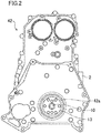
- the engine 1 illustrated in FIG. 1 is usually provided with the timing chain cover 42 illustrated in FIG. 2 .
- the timing chain cover 42 is attached to a side of the engine 1 adjacent to the transmission (transmission attaching side) where the timing chain system is provided, so that the timing chain cover 42 covers the transmission attaching side.
- the timing chain cover 42 is arranged so as not to be in contact with the chains 30, 31, 32 as well as the chain guides 33, 36, 39, the chain tensioner arms 34, 37, 40, and the chain tensioners 35, 38.
- the timing chain cover 42 has an opening from which the flywheel fastening plate 13 is exposed.
- a plate support 42a that supports the outer peripheral surface of the flywheel fastening plate 13 in a rotatable manner is arranged on the inner wall surface of the opening.
- FIG. 3 illustrates the configuration of the timing chain guide according to this embodiment.
- FIG. 4 illustrates the configuration of the oil jet according to this embodiment.
- FIG. 5 is an enlarged perspective view illustrating an area including the timing chain guide 33 and the oil jet 50 that are illustrated in FIG. 1 .
- FIG. 6 is a cross-sectional view taken along line VI-VI in FIG. 5 .
- the timing chain guide 33 has a sliding part 33c that is formed separately from the timing chain guide 33, and guides the traveling of the chain. Furthermore, the timing chain guide 33 has the pressing part 33a that extends in a bent manner from an end, of the timing chain guide 33, which is adjacent to the crankshaft 10 toward the back side (side adjacent to the cylinder block 2) of the timing chain guide 33.
- the pressing part 33a has a plate shape and is formed integrally with the timing chain guide 33.
- the pressing part 33a is in contact with the end surface (second end portion 50c) of the oil jet 50 at the back surface (surface adjacent to cylinder block 2) of the distal end portion thereof. This configuration makes it possible to prevent the oil jet 50 from falling off from the cylinder block 2 due to a hydraulic pressure.
- the timing chain guide 33 is attached to the cylinder block 2 of the engine 1 with two bolts 43.
- the oil jet 50 has, for example, the shape of a bottomed cylinder, and includes a first end portion 50b having an opening 50a communicating with an inner oil passage formed in the cylinder block 2; and a second end portion 50c located opposite to the first end portion 50b and supported on the pressing part 33a of the timing chain guide 33.
- An oil injection opening 50d is formed in a lower surface of the vicinity of the second end portion 50c of the oil jet 50, i.e., in the side surface, of the oil jet 50a, which is adjacent to the lower cylinder block 4, and oil 55 is injected through the oil injection opening 50d.
- the oil jet 50 has, for example, an anti-rotation holder 50f that is formed at an intermediate portion of the side surface of the oil jet 50, extends in the direction in which the oil injection opening 50d opens, and holds anti-rotation projection 50e.
- the anti-rotation projection 50e is a projection that prevents the rotation of the oil jet 50 having a cylindrical shape and positions the oil jet 50.
- the anti-rotation projection 50e is fitted in a hole of the cylinder block 2.
- FIG. 5 is a perspective view illustrating, on an enlarged scale, an area including the timing chain guide 33 in FIG. 1 .
- FIG. 6 is a cross-sectional view taken along line VI-VI in FIG. 5 as viewed in the downward direction of the cylinder axis.
- the oil jet 50 according to this embodiment is arranged above the meshing point between the timing chain 30 and the crankshaft sprocket wheel 11.
- the oil injection opening 50d of the oil jet 50 is directed toward the meshing point between the timing chain 30 and the crankshaft sprocket wheel 11.
- the pressing part 33a of the timing chain guide 33 is in contact with the second end portion 50c, of the oil jet 50, which is remote from the cylinder block 2 so as to support the oil jet 50.
- the flywheel fastening plate 13 arranged on the crankshaft 10 is not illustrated.
- FIG. 6 illustrates the flywheel fastening plate 13 and the timing chain cover 42.
- the proximal portion of the pressing part 33a (the body of the timing chain guide 33; the other end of the pressing part 33a) is, as viewed in the cylinder axial direction, displaced outward with respect to the cylinder block 2 (i.e., displaced in a direction away from the engine 1), relative to the distal end (one end) of the pressing part 33a.
- the pressing part 33a is in contact with the second end portion 50c of the oil jet 50 at an angle corresponding to the outward displacement.
- the pressing part 33a is comprised of a plate member that laterally presses the second end portion 50c of the oil jet 50.
- the pressing part 33a acts as a leaf spring. This makes it possible to press the second end portion 50c of the oil jet 50 with a suitable force.
- a hydraulic pressure is applied to the inside of the oil jet 50, generating a force causing the oil jet 50 to be detached in the direction toward the pressing part 33a and a case where the oil jet 50 has a length longer than the nominal length due to manufacturing variations.
- the action of leaf spring can substantially prevent an excessive reaction force that acts on the oil jet 50.
- the pressing part 33a is formed so as to extend from a part close to the bolt 43, making it possible to effectively obtain the action of leaf spring described above.
- the portion that substantially acts as a leaf spring can be formed to have a small length, and a bolt axial force can be efficiently transmitted to the second end portion 50c. This makes it possible to support the oil jet 50 with an appropriate force, in cooperation with the advantageous effect of the leaf spring action.
- the pressing part 33a is formed to have a width substantially equal to the width of the second end portion 50c of the oil jet 50. Consequently, the pressing part 33a can be formed in a compact shape. As a result, even when the area surrounded by the timing chain 30 and the crankshaft sprocket wheel 11 is narrow, the pressing part 33a can be arranged outside an area where the timing chain 30 flutters. Note that the tops of the bolts 43 of the timing chain guide 33 according to this embodiment are kept out of contact with the timing chain cover 42.
- the crankshaft 10 is provided with the crankshaft sprocket wheel 11 as the first sprocket wheel located adjacent to the engine 1, and the oil pump chain sprocket wheel 12 as the second sprocket wheel located outside with respect to the crankshaft sprocket wheel 11.
- the oil jet 50 according to this embodiment is arranged in the vicinity of the meshing point of the crankshaft sprocket wheel 11 that is located inward (adjacent to the engine 1). This arrangement reduces the distance from the oil jet 50 to the crankshaft sprocket wheel 11 and the timing chain 30.
- oil can be supplied to where the oil is needed more reliably in this embodiment than in a case where the distance from the oil jet 50 to the crankshaft sprocket wheel 11 and the timing chain 30 is long. Consequently, an amount of oil to be supplied to the oil jet 50 can be relatively reduced, thereby lowering the hydraulic pressure of the oil pump.
- the oil supply structure for the timing chain 30 can be achieved, the oil supply structure being capable of supporting the oil jet 50 without using a bolt or the like, that is, without a dedicated boss hole formed in the cylinder block 2, while reducing emission of a radiation sound from the timing chain cover 42 due to the oil jet 50.
- FIG. 7 is a partial perspective view illustrating, on an enlarged scale, an area including a timing chain guide according to the second embodiment.
- components that are the same as those of the first embodiment will be identified by the corresponding reference characters, and detailed description thereof will be omitted herein.
- a timing chain guide 33A has a pressing part 33b that is in contact with the outer end portion of the oil jet 50 (the end portion of the oil jet 50 remote from the cylinder block 2), the pressing part 33b being formed in an area between two bolts 43.
- the inward surface (which is adjacent to the cylinder block 2) of the area between two bolts 43 in the timing chain guide 33A functions as the pressing part 33b for pressing the oil jet 50.
- an oil supply structure for the timing chain 30 can be achieved, the oil supply structure being capable of supporting the oil jet 50 without using a bolt or the like, while reducing emission of a radiation sound from the timing chain cover 42 due to the oil jet 50.
- the oil supply structure for the timing chain system includes the timing chain 30 on the transmission-facing side of the engine for vehicle.
- the present invention is also applicable to an oil supply system for a timing chain of the so-called front chain system, in which the timing chain 30 is arranged on a side remote from a transmission, i.e., on the front side of the engine.
- the oil supply structure for the timing chain system is useful as an oil supply structure capable of reducing a radiation sound generated due to the supporting structure of an oil jet and, at the same time, capable of supporting easily the oil jet without depending on the structure of surrounding components such as the timing chain and the oil jet and without increasing the overall length of an engine body.
Landscapes
- Engineering & Computer Science (AREA)
- Mechanical Engineering (AREA)
- General Engineering & Computer Science (AREA)
- Devices For Conveying Motion By Means Of Endless Flexible Members (AREA)
- Lubrication Of Internal Combustion Engines (AREA)
- General Details Of Gearings (AREA)
Applications Claiming Priority (3)
| Application Number | Priority Date | Filing Date | Title |
|---|---|---|---|
| JP2016229050A JP6299849B1 (ja) | 2016-11-25 | 2016-11-25 | タイミングチェーンシステムのオイル供給構造 |
| JP2016229049A JP6264434B1 (ja) | 2016-11-25 | 2016-11-25 | タイミングチェーンシステムのオイル供給構造 |
| PCT/JP2017/037529 WO2018096842A1 (ja) | 2016-11-25 | 2017-10-17 | タイミングチェーンシステムのオイル供給構造 |
Publications (2)
| Publication Number | Publication Date |
|---|---|
| EP3530893A1 true EP3530893A1 (de) | 2019-08-28 |
| EP3530893A4 EP3530893A4 (de) | 2019-11-06 |
Family
ID=62195441
Family Applications (1)
| Application Number | Title | Priority Date | Filing Date |
|---|---|---|---|
| EP17873839.9A Withdrawn EP3530893A4 (de) | 2016-11-25 | 2017-10-17 | Ölzufuhrstruktur für steuerkettensystem |
Country Status (4)
| Country | Link |
|---|---|
| US (1) | US11371398B2 (de) |
| EP (1) | EP3530893A4 (de) |
| CN (1) | CN109983205A (de) |
| WO (1) | WO2018096842A1 (de) |
Cited By (1)
| Publication number | Priority date | Publication date | Assignee | Title |
|---|---|---|---|---|
| FR3128246A1 (fr) * | 2021-10-18 | 2023-04-21 | Renault S.A.S. | Elément de moteur à combustion interne comprenant un moyen de diffusion d’huile. |
Families Citing this family (1)
| Publication number | Priority date | Publication date | Assignee | Title |
|---|---|---|---|---|
| USD1066147S1 (en) * | 2023-07-17 | 2025-03-11 | ZZ Performance, LLC | Timing chain guide |
Family Cites Families (14)
| Publication number | Priority date | Publication date | Assignee | Title |
|---|---|---|---|---|
| JPS631855A (ja) * | 1986-06-20 | 1988-01-06 | Enuma Chain Seisakusho:Kk | 給油機能を備えたスプロケツト |
| JPH04134107A (ja) | 1990-09-26 | 1992-05-08 | Toyota Motor Corp | 可変バルブタイミング装置付内燃機関 |
| JP3092457B2 (ja) | 1994-08-24 | 2000-09-25 | スズキ株式会社 | エンジンのタイミングチェーン装架装置 |
| JPH0893890A (ja) | 1994-09-29 | 1996-04-12 | Nissan Motor Co Ltd | エンジンのチェーン潤滑装置 |
| JP2000282829A (ja) * | 1999-03-30 | 2000-10-10 | Suzuki Motor Corp | タイミングチェーンの潤滑装置 |
| DE10021220A1 (de) | 2000-04-29 | 2001-10-31 | Porsche Ag | Brennkraftmaschine mit einem Kettentrieb |
| JP2004346895A (ja) | 2003-05-26 | 2004-12-09 | Honda Motor Co Ltd | エンジン |
| DE102004005797A1 (de) * | 2004-02-06 | 2006-05-04 | Daimlerchrysler Ag | Schmiervorrichtung für eine Steuerkette an einer Brennkraftmaschine |
| JP4719624B2 (ja) | 2006-05-31 | 2011-07-06 | 本田技研工業株式会社 | 船外機 |
| JP4583338B2 (ja) | 2006-06-05 | 2010-11-17 | 本田技研工業株式会社 | ベルト式伝動機構を備えるバーチカル内燃機関 |
| JP4999470B2 (ja) * | 2007-01-18 | 2012-08-15 | 本田技研工業株式会社 | エンジン |
| US9109690B2 (en) * | 2011-10-26 | 2015-08-18 | Ford Global Technologies, Llc | Pivot pin with internal oil passage |
| JP2013142318A (ja) | 2012-01-10 | 2013-07-22 | Suzuki Motor Corp | オイルジェット構造 |
| JP6298350B2 (ja) * | 2014-04-26 | 2018-03-20 | ボーグワーナー インコーポレーテッド | オイルジェットアームおよび当該オイルジェットアームを用いたチェーンスパンの潤滑方法、ならびにチェーンテンショニング装置および当該チェーンテンショニング装置を用いたチェーンスパンの潤滑方法 |
-
2017
- 2017-10-17 CN CN201780072168.5A patent/CN109983205A/zh active Pending
- 2017-10-17 EP EP17873839.9A patent/EP3530893A4/de not_active Withdrawn
- 2017-10-17 US US16/463,036 patent/US11371398B2/en active Active
- 2017-10-17 WO PCT/JP2017/037529 patent/WO2018096842A1/ja not_active Ceased
Cited By (1)
| Publication number | Priority date | Publication date | Assignee | Title |
|---|---|---|---|---|
| FR3128246A1 (fr) * | 2021-10-18 | 2023-04-21 | Renault S.A.S. | Elément de moteur à combustion interne comprenant un moyen de diffusion d’huile. |
Also Published As
| Publication number | Publication date |
|---|---|
| US11371398B2 (en) | 2022-06-28 |
| WO2018096842A1 (ja) | 2018-05-31 |
| US20200063615A1 (en) | 2020-02-27 |
| CN109983205A (zh) | 2019-07-05 |
| EP3530893A4 (de) | 2019-11-06 |
Similar Documents
| Publication | Publication Date | Title |
|---|---|---|
| US11408311B2 (en) | Lubricant supply apparatus for chain in internal combustion engine | |
| US6336881B1 (en) | Chain drive for internal-combustion engines | |
| JP6107874B2 (ja) | エンジンの補機レイアウト | |
| US20180334928A1 (en) | Timing chain device of engine | |
| US11371398B2 (en) | Oil supply structure for timing chain system | |
| KR102810915B1 (ko) | 텐셔너 | |
| KR100652523B1 (ko) | 내연기관의 캠 체인 탈락 방지 구조 | |
| CN107849974B (zh) | 发动机的附属机件安装结构 | |
| US6447416B1 (en) | Cam drive system tensioner | |
| JP5120212B2 (ja) | 内燃機関 | |
| BR102012017547A2 (pt) | motor de combustço interna e veÍculo tipo moto equipado com o motor | |
| JP6264434B1 (ja) | タイミングチェーンシステムのオイル供給構造 | |
| JP6299849B1 (ja) | タイミングチェーンシステムのオイル供給構造 | |
| JP4543329B2 (ja) | エンジンの前部構造 | |
| JP5580026B2 (ja) | 内燃機関の動弁駆動装置 | |
| EP2589772A1 (de) | Motor und sattelfahrzeug | |
| JP4996557B2 (ja) | エンジン | |
| EP1741920A2 (de) | Verbindungsstruktur für eine Brennstoffpumpe einer Brennkraftmaschine | |
| JP4230255B2 (ja) | 内燃機関のカムチェーン脱落防止構造 | |
| EP3578788B1 (de) | Zylinderblockaufbau für motor | |
| JP2008280993A (ja) | 燃料ポンプの駆動装置 | |
| DE602005022960D1 (de) | Brennkraftmaschine | |
| JP2025115678A (ja) | 内燃機関 | |
| JP2000282829A (ja) | タイミングチェーンの潤滑装置 | |
| US20150267577A1 (en) | Oil passage structure for internal combustion engine |
Legal Events
| Date | Code | Title | Description |
|---|---|---|---|
| STAA | Information on the status of an ep patent application or granted ep patent |
Free format text: STATUS: THE INTERNATIONAL PUBLICATION HAS BEEN MADE |
|
| PUAI | Public reference made under article 153(3) epc to a published international application that has entered the european phase |
Free format text: ORIGINAL CODE: 0009012 |
|
| STAA | Information on the status of an ep patent application or granted ep patent |
Free format text: STATUS: REQUEST FOR EXAMINATION WAS MADE |
|
| 17P | Request for examination filed |
Effective date: 20190523 |
|
| AK | Designated contracting states |
Kind code of ref document: A1 Designated state(s): AL AT BE BG CH CY CZ DE DK EE ES FI FR GB GR HR HU IE IS IT LI LT LU LV MC MK MT NL NO PL PT RO RS SE SI SK SM TR |
|
| A4 | Supplementary search report drawn up and despatched |
Effective date: 20191004 |
|
| RIC1 | Information provided on ipc code assigned before grant |
Ipc: F01M 1/08 20060101AFI20190927BHEP Ipc: F01L 1/02 20060101ALI20190927BHEP Ipc: F01M 1/06 20060101ALI20190927BHEP |
|
| STAA | Information on the status of an ep patent application or granted ep patent |
Free format text: STATUS: THE APPLICATION HAS BEEN WITHDRAWN |
|
| 18W | Application withdrawn |
Effective date: 20210426 |