EP3530463B1 - Vorrichtung und verfahren zur erzeugung eines steuerparameters einer siebdruckmaschine - Google Patents
Vorrichtung und verfahren zur erzeugung eines steuerparameters einer siebdruckmaschine Download PDFInfo
- Publication number
- EP3530463B1 EP3530463B1 EP18215551.5A EP18215551A EP3530463B1 EP 3530463 B1 EP3530463 B1 EP 3530463B1 EP 18215551 A EP18215551 A EP 18215551A EP 3530463 B1 EP3530463 B1 EP 3530463B1
- Authority
- EP
- European Patent Office
- Prior art keywords
- control parameters
- inspection information
- algorithm
- candidate control
- processor
- Prior art date
- Legal status (The legal status is an assumption and is not a legal conclusion. Google has not performed a legal analysis and makes no representation as to the accuracy of the status listed.)
- Active
Links
Images


Classifications
-
- G—PHYSICS
- G06—COMPUTING OR CALCULATING; COUNTING
- G06F—ELECTRIC DIGITAL DATA PROCESSING
- G06F30/00—Computer-aided design [CAD]
- G06F30/20—Design optimisation, verification or simulation
- G06F30/27—Design optimisation, verification or simulation using machine learning, e.g. artificial intelligence, neural networks, support vector machines [SVM] or training a model
-
- B—PERFORMING OPERATIONS; TRANSPORTING
- B41—PRINTING; LINING MACHINES; TYPEWRITERS; STAMPS
- B41F—PRINTING MACHINES OR PRESSES
- B41F15/00—Screen printers
- B41F15/08—Machines
- B41F15/0881—Machines for printing on polyhedral articles
-
- B—PERFORMING OPERATIONS; TRANSPORTING
- B41—PRINTING; LINING MACHINES; TYPEWRITERS; STAMPS
- B41F—PRINTING MACHINES OR PRESSES
- B41F33/00—Indicating, counting, warning, control or safety devices
- B41F33/0036—Devices for scanning or checking the printed matter for quality control
-
- B—PERFORMING OPERATIONS; TRANSPORTING
- B41—PRINTING; LINING MACHINES; TYPEWRITERS; STAMPS
- B41M—PRINTING, DUPLICATING, MARKING, OR COPYING PROCESSES; COLOUR PRINTING
- B41M1/00—Inking and printing with a printer's forme
- B41M1/12—Stencil printing; Silk-screen printing
-
- B—PERFORMING OPERATIONS; TRANSPORTING
- B41—PRINTING; LINING MACHINES; TYPEWRITERS; STAMPS
- B41M—PRINTING, DUPLICATING, MARKING, OR COPYING PROCESSES; COLOUR PRINTING
- B41M3/00—Printing processes to produce particular kinds of printed work, e.g. patterns
-
- G—PHYSICS
- G06—COMPUTING OR CALCULATING; COUNTING
- G06F—ELECTRIC DIGITAL DATA PROCESSING
- G06F30/00—Computer-aided design [CAD]
- G06F30/30—Circuit design
-
- G—PHYSICS
- G06—COMPUTING OR CALCULATING; COUNTING
- G06F—ELECTRIC DIGITAL DATA PROCESSING
- G06F30/00—Computer-aided design [CAD]
- G06F30/30—Circuit design
- G06F30/32—Circuit design at the digital level
- G06F30/33—Design verification, e.g. functional simulation or model checking
- G06F30/3308—Design verification, e.g. functional simulation or model checking using simulation
-
- G—PHYSICS
- G06—COMPUTING OR CALCULATING; COUNTING
- G06F—ELECTRIC DIGITAL DATA PROCESSING
- G06F30/00—Computer-aided design [CAD]
- G06F30/30—Circuit design
- G06F30/32—Circuit design at the digital level
- G06F30/337—Design optimisation
-
- G—PHYSICS
- G06—COMPUTING OR CALCULATING; COUNTING
- G06F—ELECTRIC DIGITAL DATA PROCESSING
- G06F30/00—Computer-aided design [CAD]
- G06F30/30—Circuit design
- G06F30/39—Circuit design at the physical level
- G06F30/398—Design verification or optimisation, e.g. using design rule check [DRC], layout versus schematics [LVS] or finite element methods [FEM]
-
- H—ELECTRICITY
- H05—ELECTRIC TECHNIQUES NOT OTHERWISE PROVIDED FOR
- H05K—PRINTED CIRCUITS; CASINGS OR CONSTRUCTIONAL DETAILS OF ELECTRIC APPARATUS; MANUFACTURE OF ASSEMBLAGES OF ELECTRICAL COMPONENTS
- H05K3/00—Apparatus or processes for manufacturing printed circuits
- H05K3/0005—Apparatus or processes for manufacturing printed circuits for designing circuits by computer
-
- H—ELECTRICITY
- H05—ELECTRIC TECHNIQUES NOT OTHERWISE PROVIDED FOR
- H05K—PRINTED CIRCUITS; CASINGS OR CONSTRUCTIONAL DETAILS OF ELECTRIC APPARATUS; MANUFACTURE OF ASSEMBLAGES OF ELECTRICAL COMPONENTS
- H05K3/00—Apparatus or processes for manufacturing printed circuits
- H05K3/10—Apparatus or processes for manufacturing printed circuits in which conductive material is applied to the insulating support in such a manner as to form the desired conductive pattern
- H05K3/12—Apparatus or processes for manufacturing printed circuits in which conductive material is applied to the insulating support in such a manner as to form the desired conductive pattern using thick film techniques, e.g. printing techniques to apply the conductive material or similar techniques for applying conductive paste or ink patterns
- H05K3/1216—Apparatus or processes for manufacturing printed circuits in which conductive material is applied to the insulating support in such a manner as to form the desired conductive pattern using thick film techniques, e.g. printing techniques to apply the conductive material or similar techniques for applying conductive paste or ink patterns by screen printing or stencil printing
-
- H—ELECTRICITY
- H05—ELECTRIC TECHNIQUES NOT OTHERWISE PROVIDED FOR
- H05K—PRINTED CIRCUITS; CASINGS OR CONSTRUCTIONAL DETAILS OF ELECTRIC APPARATUS; MANUFACTURE OF ASSEMBLAGES OF ELECTRICAL COMPONENTS
- H05K3/00—Apparatus or processes for manufacturing printed circuits
- H05K3/30—Assembling printed circuits with electric components, e.g. with resistors
- H05K3/32—Assembling printed circuits with electric components, e.g. with resistors electrically connecting electric components or wires to printed circuits
- H05K3/34—Assembling printed circuits with electric components, e.g. with resistors electrically connecting electric components or wires to printed circuits by soldering
- H05K3/341—Surface mounted components
-
- B—PERFORMING OPERATIONS; TRANSPORTING
- B41—PRINTING; LINING MACHINES; TYPEWRITERS; STAMPS
- B41P—INDEXING SCHEME RELATING TO PRINTING, LINING MACHINES, TYPEWRITERS, AND TO STAMPS
- B41P2215/00—Screen printing machines
- B41P2215/50—Screen printing machines for particular purposes
-
- G—PHYSICS
- G01—MEASURING; TESTING
- G01N—INVESTIGATING OR ANALYSING MATERIALS BY DETERMINING THEIR CHEMICAL OR PHYSICAL PROPERTIES
- G01N21/00—Investigating or analysing materials by the use of optical means, i.e. using sub-millimetre waves, infrared, visible or ultraviolet light
- G01N21/84—Systems specially adapted for particular applications
- G01N21/88—Investigating the presence of flaws or contamination
- G01N21/95—Investigating the presence of flaws or contamination characterised by the material or shape of the object to be examined
- G01N21/956—Inspecting patterns on the surface of objects
- G01N2021/95638—Inspecting patterns on the surface of objects for PCB's
- G01N2021/95646—Soldering
-
- G—PHYSICS
- G01—MEASURING; TESTING
- G01N—INVESTIGATING OR ANALYSING MATERIALS BY DETERMINING THEIR CHEMICAL OR PHYSICAL PROPERTIES
- G01N21/00—Investigating or analysing materials by the use of optical means, i.e. using sub-millimetre waves, infrared, visible or ultraviolet light
- G01N21/84—Systems specially adapted for particular applications
- G01N21/88—Investigating the presence of flaws or contamination
- G01N21/95—Investigating the presence of flaws or contamination characterised by the material or shape of the object to be examined
- G01N21/956—Inspecting patterns on the surface of objects
- G01N2021/95638—Inspecting patterns on the surface of objects for PCB's
- G01N2021/95661—Inspecting patterns on the surface of objects for PCB's for leads, e.g. position, curvature
- G01N2021/95669—Inspecting patterns on the surface of objects for PCB's for leads, e.g. position, curvature for solder coating, coverage
-
- G—PHYSICS
- G06—COMPUTING OR CALCULATING; COUNTING
- G06F—ELECTRIC DIGITAL DATA PROCESSING
- G06F2119/00—Details relating to the type or aim of the analysis or the optimisation
-
- G—PHYSICS
- G06—COMPUTING OR CALCULATING; COUNTING
- G06F—ELECTRIC DIGITAL DATA PROCESSING
- G06F2119/00—Details relating to the type or aim of the analysis or the optimisation
- G06F2119/18—Manufacturability analysis or optimisation for manufacturability
-
- H—ELECTRICITY
- H05—ELECTRIC TECHNIQUES NOT OTHERWISE PROVIDED FOR
- H05K—PRINTED CIRCUITS; CASINGS OR CONSTRUCTIONAL DETAILS OF ELECTRIC APPARATUS; MANUFACTURE OF ASSEMBLAGES OF ELECTRICAL COMPONENTS
- H05K13/00—Apparatus or processes specially adapted for manufacturing or adjusting assemblages of electric components
- H05K13/08—Monitoring manufacture of assemblages
- H05K13/081—Integration of optical monitoring devices in assembly lines; Processes using optical monitoring devices specially adapted for controlling devices or machines in assembly lines
- H05K13/0817—Monitoring of soldering processes
-
- H—ELECTRICITY
- H05—ELECTRIC TECHNIQUES NOT OTHERWISE PROVIDED FOR
- H05K—PRINTED CIRCUITS; CASINGS OR CONSTRUCTIONAL DETAILS OF ELECTRIC APPARATUS; MANUFACTURE OF ASSEMBLAGES OF ELECTRICAL COMPONENTS
- H05K2203/00—Indexing scheme relating to apparatus or processes for manufacturing printed circuits covered by H05K3/00
- H05K2203/16—Inspection; Monitoring; Aligning
- H05K2203/163—Monitoring a manufacturing process
-
- H—ELECTRICITY
- H05—ELECTRIC TECHNIQUES NOT OTHERWISE PROVIDED FOR
- H05K—PRINTED CIRCUITS; CASINGS OR CONSTRUCTIONAL DETAILS OF ELECTRIC APPARATUS; MANUFACTURE OF ASSEMBLAGES OF ELECTRICAL COMPONENTS
- H05K3/00—Apparatus or processes for manufacturing printed circuits
- H05K3/30—Assembling printed circuits with electric components, e.g. with resistors
- H05K3/32—Assembling printed circuits with electric components, e.g. with resistors electrically connecting electric components or wires to printed circuits
- H05K3/34—Assembling printed circuits with electric components, e.g. with resistors electrically connecting electric components or wires to printed circuits by soldering
- H05K3/3465—Application of solder
- H05K3/3485—Application of solder paste, slurry or powder
Definitions
- the present disclosure relates to an apparatus, a recording medium, and a method for generating a control parameter of a screen printer that prints solder paste on a substrate.
- the present disclosure is derived from research conducted under the Robot Industry Fusion Core Technology Development Project of the Ministry of Trade, Industry, and Energy of Korea [Project number: 10077589, Project title: Development of technology for machine learning-based SMT optimization system].
- a process of mounting electronic components on a printed circuit board is performed in such an order that a solder is applied to a pad of a printed circuit board through a solder printer (i.e., a screen printer), the state of the applied solder is inspected using a solder inspection device, and then electronic components are mounted on the printed circuit board with the solder applied.
- a solder printer i.e., a screen printer
- the screen printer positions the printed circuit board on a table for fixing the printed circuit board (bare board) and arranges a stencil mask on the printed circuit board so that an opening of the stencil mask is located on the corresponding pad of the printed circuit board.
- the screen printer moves a squeegee blade by controlling a pressure and moving speed of the squeegee blade based on a control parameter, and separates the stencil mask from the printed circuit board by controlling a separation speed between the stencil mask and the printed circuit board.
- US 2004244613 discloses a method for implementing hybrid, closed-loop control that generates control values for processes, wherein a first, coarse algorithm is used to rapidly produce the value of a stencil printer control value resulting in a solder paste deposit having a volume within predetermined acceptable limits, and after the coarse algorithm no longer produces solder paste deposits closer to a desired volume, a second, more refined estimator is used to fine tune the process. An additional transitional algorithm may be added between the coarse algorithm and refined estimator.
- US 6587580 B1 discloses a system for determining the optimal settings for parameter of a stencil printing machine, wherein the system generates a model mapping parameter inputs to output results, and the model is then used to determine the optimal settings of parameter inputs in order to produce the desired results.
- solder paste In printing the solder paste using the screen printer, a larger or smaller amount of solder paste than a reference amount may be printed on pads of a printed circuit board or solder paste may be printed at an inappropriate position depending on control parameters. Further, a defect may occur in a solder printed on pads of the printed circuit board depending on the ambient conditions (e.g., temperature or humidity) of the screen printer or the type of the stencil mask.
- ambient conditions e.g., temperature or humidity
- an apparatus for generating a control parameter for a screen printer includes: a memory that stores a simulation model that is trained to derive predictive inspection information on printed states of a plurality of virtual solder pastes based on a plurality of control parameters of the screen printer; and at least two algorithms among an optimization algorithm, a search algorithm, and a machine learning-based reinforcement learning algorithm for generating a plurality of candidate control parameters for the screen printer; a communication circuit configured to receive first inspection information on printed states of a plurality of solder pastes, the plurality of solder pastes being printed by the screen printer based on a first control parameter; and a processor electrically connected to the memory and the communication circuit, wherein the processor is configured to: obtain first predictive inspection information on a printed state of a first virtual solder paste by applying the first control parameter to the simulation model; generate a plurality of first candidate control parameters based on the first predictive inspection information and a first algorithm of the at least two algorithms; generate a plurality of second candidate control parameters based on the first predictive
- Each of the first control parameter and the plurality of second control parameters include s at least one of a pressure applied to a squeegee blade of the screen printer, a moving speed of the squeegee blade, and a separation speed between a stencil mask of the screen printer and a substrate.
- the first inspection information includes at least one of a volume, an area, a height, a width, and a slope of each of the solder pastes.
- the first predictive inspection information includes at least one of the volume, the area, the height, the width, and the slope of each of the first virtual solder pastes.
- the processor is further configured to: calculate the difference between the first inspection information and the first predictive inspection information; compare the calculated difference with the predetermined threshold value; update the simulation model using the first inspection information and the first predictive inspection information if it is determined that the calculated difference is greater than the predetermined threshold value.
- the simulation model includes a machine learning-based regression model.
- the memory further stores an optimization algorithm and a search algorithm to generate the plurality of candidate control parameters for the screen printer, and the processor is further configured to: generate a plurality of first candidate control parameters by applying the first predictive inspection information to the optimization algorithm; and generate a plurality of second candidate control parameters by applying the first predictive inspection information to the search algorithm.
- the processor is further configured to: calculate a difference between the first inspection information and the first predictive inspection information; and compare the calculated difference with a predetermined threshold value.
- the processor is further configured to, if the calculated difference is greater than the predetermined threshold value: select a first number of first candidate control parameters from among the plurality of first candidate control parameters; select a second number of second candidate control parameters from the plurality of second candidate control parameters, wherein the second number is greater than the first number; and determine the plurality of second control parameters among the selected first candidate control parameters and the selected second candidate control parameters.
- the processor is further configured to, if the calculated difference is less than or equal to the predetermined threshold value: select a first number of first candidate control parameters from the plurality of first candidate control parameters; select a second number of second candidate control parameters from the plurality of second candidate control parameters, wherein the second number is smaller than the first number; and determine the plurality of second control parameters among the selected first candidate control parameters and the selected second candidate control parameters.
- the memory further stores an optimization algorithm and a machine learning-based reinforcement learning algorithm to generate the plurality of candidate control parameters for the screen printer, and the processor is further configured to: generate a plurality of first candidate control parameters by applying the first predictive inspection information to the optimization algorithm; and generate a plurality of second candidate control parameters by applying the first control parameter and the first predictive inspection information to the machine learning-based reinforcement learning algorithm.
- the processor is further configured to: calculate a difference between the first inspection information and the first predictive inspection information; compare the calculated difference with a predetermined threshold value to generate a comparison result.
- the processor is further configured to: select a first number of first candidate control parameters from among the plurality of first candidate control parameters. if it is determined that the calculated difference is greater than a predetermined threshold value; select a second number of second candidate control parameters from among the plurality of second candidate control parameters, where the second number is greater than the first number; and determine the plurality of second control parameters based on the selected first candidate control parameters and the selected second candidate control parameters.
- the communication circuit is configured to receive second inspection information corresponding to each of the plurality of second control parameters, and the processor is further configured to obtain second predictive inspection information on a printed state of a second virtual solder paste by applying each of the plurality of second control parameters to the simulation model.
- the processor is further configured to: calculate an average value of the differences between the second inspection information and the second predictive inspection information; select one of the plurality of second control parameters if the calculated average value corresponds to a predetermined value; and transmit the selected second control parameter to the screen printer through the communication circuit.
- unit refers to a software element or a hardware element, such as a Field-Programmable Gate Array (FPGA) or an Application-Specific Integrated Circuit (ASIC).
- FPGA Field-Programmable Gate Array
- ASIC Application-Specific Integrated Circuit
- the "unit” is not limited to software or hardware.
- the “unit” may be configured either to be stored in an addressable storage medium or to execute one or more processors. Therefore, the “unit” includes, for example, software elements, object-oriented software elements, class elements or task elements, processes, functions, properties, procedures, sub-routines, segments of a program code, drivers, firmware, micro-codes, circuits, data, database, data structures, tables, arrays, and parameters.
- the elements and functions provided by the "unit” may be either combined into a smaller number of elements or “unit”, or divided into additional elements or "unit”.
- the expression "based on” used herein is used to describe one or more factors that affect a decision, a judgment, or an operation described in a phrase or sentence including this expression and does not exclude the existence of an additional factor that affects the decision, the judgment, or the operation.
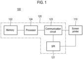
- FIG. 1 is a block diagram schematically illustrating a configuration of an inspection system according to one exemplary embodiment of the present disclosure.
- an inspection system 100 includes a screen printer 110 and a control parameter generation device 120.
- the screen printer 110 When a substrate (bare substrate, hereinafter referred to as a "printed circuit board") is transferred from the outside, the screen printer 110 prints solder paste on a plurality of pads of the transferred printed circuit board.
- the screen printer 110 includes a squeegee blade and a stencil mask. The screen printer 110 prints the solder paste on the printed circuit board located below the stencil mask through a plurality of openings of the stencil mask by moving the squeegee blade.
- the screen printer 110 prints the solder paste on the plurality of pads of the printed circuit board according to control parameters.
- the control parameters include at least one of a pressure applied to the squeegee blade, a moving speed of the squeegee blade, and a separation speed between the stencil mask and the printed circuit board.
- the control parameters are not necessarily limited thereto.
- the control parameters include various parameters related to printing of the solder paste.
- the control parameter generation device 120 is connected to the screen printer 110 through a network (not shown) via wireless communication or wired communication.
- the wireless communication includes, for example, cellular communication (e.g., LTE, LTE Advanced (LTE-A), Code Division Multiple Access (CDMA), Wideband CDMA (WCDMA), Universal Mobile Telecommunications System (UMTS), and Wireless Broadband (WiBro)).
- the wireless communication also includes short-range wireless communication (e.g., Wireless Fidelity (Wi-Fi), Light Fidelity (Li-Fi), Bluetooth, Bluetooth Low Energy (BLE), ZigBee, and Near-Field Communication (NFC).
- the screen printer 110 is connected with an inspection device 121 and a processor 124 via communication lines, thereby setting up a connection so that data communication is performed therebetween.
- the control parameter generation device 120 includes the inspection device 121, a memory 122, a communication circuit 123, and the processor 124.
- the inspection device 121 is illustrated as being included in the control parameter generation device 120 in FIG. 1 but is not necessarily limited thereto.
- the inspection device 121 is configured separately from the control parameter generation device 120.
- the memory 122 and the processor 124 are illustrated as being configured separately from the inspection device 121 in FIG. 1 but are not necessarily limited thereto.
- the memory 122 and the processor 124 are included in the inspection device 121.
- the memory 122 and the processor 124 may be present on a surface mount technology (SMT) line as an integrated server and may be located externally via a wired or wireless communication.
- SMT surface mount technology
- the inspection device (SPI, solder paste inspection) 121 inspects the printed state of the solder paste on the transferred printed circuit board. For example, the inspection device 121 irradiates light to the printed circuit board on which the solder paste is printed, and receives light reflected from the printed circuit board, thereby obtaining image data on the printed circuit board.
- the inspection device 121 compares the image data on the printed circuit board with reference data for determining whether the printed state of the solder paste is good or bad, thereby inspecting whether the solder paste printed on the printed circuit board is defective. For example, the inspection device 121 checks whether the solder paste printed on the printed circuit board is printed in a proper amount at a proper position, thereby inspecting whether the solder paste is defective, and generates inspection information indicating an inspection result.
- the inspection information includes at least one of a volume, an area, a height, a width, and a slope of the solder paste printed by the screen printer 110.
- the memory 122 stores a simulation model for deriving predictive inspection information about the printed state of the solder paste based on a plurality of control parameters of the screen printer 110.
- the solder paste associated with the predictive inspection information is a virtual solder paste generated by the simulation model.
- the simulation model includes a machine learning-based regression model that is trained to derive the predictive inspection information indicating a predicted printed state of the solder paste based on the plurality of control parameters of the screen printer 110.
- the machine learning-based regression model is a machine learning-based model that simulates the actual conditions of the screen printer 110 and is a model that adaptively changes depending on changes in the environment.
- the machine learning-based regression model is trained based on the control parameters of the screen printer 110 and the inspection information by the inspection device 121, and generates predictive information on the printed state of the solder paste as a result of learning.
- the machine learning-based regression model may be trained based on print parameter information in addition to the control parameters and the inspection information.
- the predictive inspection information includes at least one of a volume, an area, a height, a width, and a slope of the first virtual solder paste.
- the present disclosure is not limited thereto. Instead, various information related to the solder paste, which can be inspected by the inspection device 121, may be used as the predictive inspection information.
- the print parameter information indicates a parameter for printing the solder paste by the screen printer 110 and includes at least one of an ambient temperature of the screen printer 110, an ambient humidity of the screen printer 110, a shape of each of the pads of the printed circuit board, an area ratio of each of the pads of the printed circuit board, and an aspect ratio of each of the pads of the printed circuit board.
- these are provided merely for illustration, and the present disclosure is not limited thereto. Instead, various parameters that affect the printing of the solder paste by the screen printer 110 may be used as the print parameter information.
- the memory 122 further stores at least two algorithms among an optimization algorithm, a search algorithm, and a machine learning-based reinforcement learning algorithm for generating a plurality of candidate control parameters for the screen printer 110.
- the memory 122 stores the optimization algorithm and the search algorithm.
- the memory 122 stores the optimization algorithm and the machine learning-based reinforcement learning algorithm.
- the memory 122 stores the search algorithm and the machine learning-based reinforcement learning algorithm.
- the memory 122 stores the optimization algorithm, the search algorithm, and the machine learning-based reinforcement learning algorithm.
- the memory 122 is a magnetic disk (e.g., a magnetic tape, a flexible disk, and a hard disk), an optical disk (e.g., a CD and a DVD), and a semiconductor memory (e.g., an RAM, an ROM, a flash memory, and a USB or SD card including a flash memory).
- a magnetic disk e.g., a magnetic tape, a flexible disk, and a hard disk
- an optical disk e.g., a CD and a DVD
- a semiconductor memory e.g., an RAM, an ROM, a flash memory, and a USB or SD card including a flash memory.
- the communication circuit 123 is connected to the screen printer 110 and the inspection device 121 via the network. In one exemplary embodiment, the communication circuit 123 receives inspection information from the inspection device 121. In addition, the communication circuit 123 transmits a control parameter generated by the processor 124 to the screen printer 110.
- the processor 124 is electrically connected to the memory 122 and the communication circuit 123.
- the processor 124 loads the simulation model stored in the memory 122 and applies a control parameter to the loaded simulation model, thereby obtaining predictive inspection information indicating a predicted printed state of the solder paste.
- the solder paste associated with the predictive inspection information is a virtual solder paste generated by the simulation model.
- the processor 124 generates a plurality of candidate control parameters based on the predictive inspection information, and selects a plurality of control parameters from among the plurality of candidate control parameters based on the inspection information and the predictive inspection information.
- the plurality of control parameters is transmitted to the screen printer 110 via the communication circuit 123.
- the processor 124 includes a simulation model unit 210, an optimization algorithm unit 220, a search algorithm unit 230, a reinforcement learning algorithm unit 240, and a parameter determination unit 250.
- the simulation model unit 210 loads the simulation model stored in the memory 122, and applies a first control parameter to the simulation model, thereby generating predictive inspection information (hereinafter, referred to as "first predictive inspection information").
- first predictive inspection information includes at least one of the pressure applied to the squeegee blade of the screen printer 110, the moving speed of the squeegee blade, and the separation speed between the stencil mask and the printed circuit board.
- the simulation model unit 210 updates the simulation model stored in the memory 122 based on inspection information corresponding to the first control parameter (hereinafter, referred to as "first inspection information”) and the first predictive inspection information.
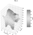
- FIG. 3 illustrates an example of first predictive inspection information according to one exemplary embodiment of the present disclosure.
- FIG. 3 shows the first predictive inspection information (e.g., the volume of the solder paste) generated when a first control parameter including the moving speed (print speed) of the squeegee blade and the pressure applied to the squeegee blade is applied to the machine learning-based regression model according to the present embodiment.
- This first predictive inspection information is used to generate control parameters for the screen printer 110 along with the inspection information by the inspection device 121.
- a reward refers to a print quality index of the solder paste, and the quality index includes a volume, an average volume, a volume standard deviation, a process capability index (CPIK), a Z-score, cumulative distribution function of solder applied.
- FIG. 3 shows the volume of lead applied as the reward.
- the optimization algorithm unit 220 loads the optimization algorithm stored in the memory 122, and applies the first predictive inspection information generated by the simulation model unit 210 to the optimization algorithm, thereby generating a plurality of candidate control parameters (hereinafter, "first candidate control parameters").
- the optimization algorithm includes a mathematical optimization method, for example, a gradient descent method, a simulated annealing method or the like.
- the optimization algorithm generates a first candidate control parameter that is close to an optimal control parameter as the match rate between the machine learning-based regression model and an actual solder paste print process is higher.
- the search algorithm unit 230 loads the search algorithm stored in the memory 122, and applies the first predictive inspection information generated by the simulation model unit 210 to the search algorithm, thereby generating a plurality of candidate control parameters (hereinafter, "second candidate control parameters").
- the search algorithm is an algorithm for finding data that meets a certain condition or property from a given data set. For example, as shown in FIG.
- the search algorithm unit 230 applies first predictive inspection information 420 to the search algorithm, thereby selecting four pieces of predictive inspection information 410 based on the first predictive inspection information 420, detecting predictive inspection information 430 positioned at the center of the four pieces of selected predictive inspection information 410, and generating a control parameter corresponding to the detected predictive inspection information 430 as a second candidate control parameter corresponding to the first predictive inspection information 420.
- the reinforcement learning algorithm unit 240 loads the machine learning-based reinforcement learning algorithm stored in the memory 122, and applies the first control parameter and the first predictive inspection information to the machine learning-based reinforcement learning algorithm, thereby generating a plurality of candidate controls parameters (hereinafter, referred to as "third candidate control parameters").
- the machine learning-based reinforcement learning algorithm is an algorithm of selecting and conducting one of the possible actions in a condition and receiving a reward resulting from the action, which can recommend a candidate control parameter corresponding to the first predictive inspection information by learning a tuning policy of the control parameter.
- the machine learning-based reinforcement learning algorithm includes a Q-leaming algorithm, a Deep-Q-Network (DQN) algorithm or the like.
- the parameter determination unit 250 generates a plurality of control parameters (hereinafter, referred to as "second control parameters") based on the plurality of first candidate control parameters, the plurality of second candidate control parameters, and the plurality of third candidate control parameters.
- second control parameters a plurality of control parameters
- the parameter determination unit 250 generates the plurality of second control parameters among the plurality of first candidate control parameters, the plurality of second candidate control parameters, and the plurality of third candidate control parameters based on the first inspection information and the first predictive inspection information.
- the processor 124 includes the simulation model unit 210, the optimization algorithm unit 220, the search algorithm unit 230, and the parameter determination unit 250.
- the parameter determination unit 250 generates the plurality of second control parameters based on the plurality of first candidate control parameters generated by the optimization algorithm unit 220 and the plurality of second candidate control parameters generated by the search algorithm unit 230.
- the processor 124 includes the simulation model unit 210, the optimization algorithm unit 220, the reinforcement learning algorithm unit 240, and the parameter determination unit 250.
- the parameter determination unit 250 generates the plurality of second control parameters based on the plurality of first candidate control parameters generated by the optimization algorithm unit 220 and the plurality of third candidate control parameters generated by the reinforcement learning algorithm unit 240.
- the processor 124 includes the simulation model unit 210, the search algorithm unit 230, the reinforcement learning algorithm unit 240, and the parameter determination unit 250.
- the parameter determination unit 250 generates the plurality of second control parameters based on the plurality of second candidate control parameters generated by the search algorithm unit 230 and the plurality of third candidate control parameters generated by the reinforcement learning algorithm unit 240.
- FIG. 5 is a flowchart illustrating a method of providing a plurality of control parameters according to one exemplary embodiment of the present disclosure.
- step S502 the processor 124 obtains first predictive inspection information based on a first control parameter. For example, the processor 124 applies the first control parameter to the simulation model, thereby obtaining the first predictive inspection information.
- the processor 124 receives first inspection information corresponding to the first control parameter.
- the first inspection information includes at least one of the volume, area, height, width, and slope of the solder paste.
- the processor 124 receives the first inspection information corresponding to the first control parameter from the inspection device 121 via the communication circuit 123.
- the processor 124 generates a plurality of candidate control parameters based on the first predictive inspection information.
- the processor 124 applies the first predictive inspection information to an optimization algorithm and a search algorithm, which are stored in the memory 122, thereby generating the plurality of candidate control parameters.
- the processor 124 applies the first predictive inspection information to the optimization algorithm and a machine learning-based reinforcement learning algorithm, which are stored in memory 122, thereby generating the plurality of candidate control parameters.
- the processor 124 applies the first predictive inspection information to the search algorithm and the machine learning-based reinforcement learning algorithm, which are stored in memory 122, thereby generating the plurality of candidate control parameters.
- the processor 124 applies the first predictive inspection information to the optimization algorithm, the search algorithm, and the machine learning-based reinforcement learning algorithm, which are stored in memory 122, thereby generating the plurality of candidate control parameters.
- step S508 the processor 124 generates a plurality of second control parameters from the plurality of candidate control parameters based on the first inspection information and the first predictive inspection information. For example, the processor 124 selects the plurality of second control parameters from among the plurality of candidate control parameters based on the first inspection information and the first predictive inspection information.
- step S510 the processor 124 transmits the plurality of second control parameters to the screen printer 110.
- the processor 124 transmits the plurality of second control parameters to the screen printer 110 via the communication circuit 123.
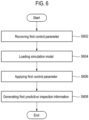
- FIG. 6 is a flowchart illustrating a method of generating first predictive inspection information according to one exemplary embodiment of the present disclosure.
- step S602 the processor 124 receives a first control parameter.
- the first control parameter is received via a user input unit (not shown) of the inspection system 100.
- the first control parameter is received from the screen printer 110 via the communication circuit 123.
- step S604 the processor 124 loads a simulation model.
- the simulation model unit 210 of the processor 124 connects to the memory 122 upon receipt of the first control parameter, and loads the simulation model stored in the memory 122.
- step S606 the processor 124 applies the first control parameter to the loaded simulation model.
- the simulation model unit 210 of the processor 124 applies the first control parameter to the simulation model.
- step S608 the processor 124 generates first predictive inspection information about the printed state of solder paste corresponding to the first control parameter.
- the solder paste associated with the predictive inspection information is a virtual solder paste generated by the simulation model.
- the first predictive inspection information is generated as an output from the simulation model.
- the simulation model unit 210 of the processor 124 inputs the first control parameter to the simulation model, thereby generating the first predictive inspection information corresponding to the first control parameter, as shown in FIG. 3 .
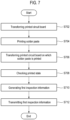
- FIG. 7 is a flowchart illustrating a method of generating first inspection information according to one exemplary embodiment of the present disclosure.
- step S702 the screen printer 110 receives a printed circuit board.
- the printed circuit board on which solder paste is to be printed is transferred from the outside to the screen printer 110.
- step S704 the screen printer 110 prints the solder paste on the transferred printed circuit board based on a first control parameter.
- the screen printer 110 sets the first control parameter as a control parameter of the screen printer 110, and prints the solder paste on each of a plurality of pads of the printed circuit board according to the set first control parameter.
- step S706 the inspection device 121 receives the printed circuit board on which the solder paste is printed.
- the printed circuit board on which the screen printer 110 has completed printing the solder paste is transferred to the inspection device 121.
- the inspection device 121 checks the printed state of the printed circuit board on which the solder paste is printed.
- the inspection device 121 irradiates light to the printed circuit board on which the solder paste is printed, and receives light reflected from the printed circuit board, thereby obtaining image data corresponding to the printed circuit board.
- the inspection device 121 inspects the printed state (for example, at least one of the volume, area, height, width, and slope) of the solder paste with reference to the image data based on reference data for determining whether the printed state of the solder paste is good or bad.
- the inspection device 121 generates first inspection information corresponding to the first control parameter.
- the inspection device 121 generates the first inspection information (for example, inspection information about at least one of the volume, area, height, width, and slope of the solder paste) obtained by inspecting the printed state of the solder paste printed on the printed circuit board by the screen printer 110 according to the first control parameter.
- step S712 the inspection device 121 transmits the first inspection information via the communication circuit 123.
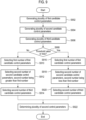
- FIG. 8 is a flowchart illustrating a method of updating a simulation model and a reinforcement learning algorithm according to one exemplary embodiment of the present disclosure.
- step S802 the processor 124 receives first inspection information.
- the parameter determination unit 250 of the processor 124 receives the first inspection information from the inspection device 121 via the communication circuit 123.
- step S804 the processor 124 calculates a difference between the first inspection information and the first predictive inspection information.
- Equation 1 E represents the difference, B R represents inspection information, R(B P ) represents predictive information, n represents the number of control parameters (i.e., the number of printed circuit boards on which solder paste is printed by the screen printer 110).
- step S806 the processor 124 compares the difference between the first inspection information and the first predictive inspection information with a predetermined threshold value.
- the processor 124 determines whether the difference between the first inspection information and the first predictive inspection information is less than or equal to the predetermined threshold value. For example, the parameter determination unit 250 of the processor 124 compares the calculated difference with the predetermined threshold value, and determines whether the calculated difference is less than or equal to the predetermined threshold value.
- the processor 124 updates a simulation model based on the first inspection information and the first predictive inspection information in step S810. For example, the parameter determination unit 250 of the processor 124 updates the first predictive inspection information corresponding to the first control parameter to the first inspection information for the simulation model stored in the memory 122.
- the processor 124 updates a machine learning-based reinforcement learning algorithm based on the simulation model in step S812.
- the parameter determination unit 250 of the processor 124 applies a plurality of control parameters of the simulation model stored in the memory 122 and the predictive inspection information corresponding to the control parameters to the machine learning-based reinforcement learning algorithm stored in the memory 122, thereby updating the machine learning-based reinforcement learning algorithm.
- FIG. 9 is a flowchart illustrating a method of determining a plurality of second control parameters according to one exemplary embodiment of the present disclosure.
- step S902 the processor 124 generates a plurality of candidate control parameters (hereinafter, referred to as "first candidate control parameters”) by applying first predictive inspection information to an optimization algorithm.
- step S904 the processor 124 generates a plurality of candidate control parameters (hereinafter, referred to as "second candidate control parameters”) by applying the first predictive inspection information to a search algorithm.
- step S906 the processor 124 generates a plurality of candidate control parameters (hereinafter, referred to as "third candidate control parameters”) by applying a first control parameter and the first predictive inspection information to a machine learning-based reinforcement learning algorithm.
- the optimization algorithm unit 220 of the processor 124 loads the optimization algorithm from the memory 122, and applies the first predictive inspection information generated by the simulation model unit 210 to the optimization algorithm, thereby generating the plurality of first candidate control parameters.
- the search algorithm unit 230 of the processor 124 loads the search algorithm from the memory 122, and applies the first predictive inspection information generated by the simulation model unit 210 to the search algorithm, thereby generating the plurality of second candidate control parameters.
- the reinforcement learning algorithm unit 240 of the processor 124 loads the machine learning-based reinforcement learning algorithm from the memory 122, and applies the first control parameter and the first predictive inspection information generated by the simulation model unit 210 to the machine learning-based reinforcement learning algorithm, thereby generating the plurality of third candidate control parameters.
- step S908 the processor 124 compares the difference between first inspection information and the first predictive inspection information with a predetermined threshold value, thereby determining whether the difference between the first inspection information and the first predictive inspection information is less than or equal to the predetermined threshold value.
- step S908 the processor 124 selects a first number of first candidate control parameters from among the plurality of first candidate control parameters in operation S910. In step S912, the processor 124 selects a second number of second candidate control parameters from among the plurality of second candidate control parameters, where the second number is greater than the first number, in operation S912. In step S914, the processor 124 selects the second number of third candidate control parameters from among the plurality of third candidate control parameters in operation.
- the parameter determination unit 250 of the processor 124 arranges the plurality of first candidate control parameters as shown in FIG. 10 .
- the parameter determination unit 250 obtains a process capability index (CPK) for each of the plurality of first candidate control parameters, calculates aZ-score of the obtained process capability index, and arranges the plurality of first candidate control parameters according to the calculated Z-score.
- the parameter determination unit 250 selects the first number (e.g., two) of first candidate control parameters (P O1 and P O2 ) from among the plurality of first candidate control parameters (P O1 to P O10 ) illustrated in FIG. 10 .
- the parameter determination unit 250 obtains the process capability index for each of the plurality of second candidate control parameters, calculates the Z-score of the obtained process capability index, and arranges the plurality of second candidate control parameters according to the calculated Z-score as shown in FIG. 10 .
- the parameter determination unit 250 selects the second number (e.g., four) of second candidate control parameters (P L1 to P L4 ) from among the plurality of second candidate control parameters (P L1 to P L10 ) illustrated in FIG. 10 , where the second number is greater than the first number.
- the parameter determination unit 250 obtains the process capability index for each of the plurality of third candidate control parameters, calculates the Z-score of the obtained process capability index, and arranges the plurality of third candidate control parameters according to the calculated Z-score as shown in FIG. 10 .
- the parameter determination unit 250 selects the second number (for example, four) of third candidate control parameters (P R1 to P R4 ) from among the plurality of third candidate control parameters (P R1 to P R10 ) illustrated in FIG. 10 .
- step S908 If it is determined that the difference between the first inspection information and the first predictive inspection information is less than or equal to the predetermined threshold value in step S908, the processor 124 selects a first number of first candidate control parameters from among the plurality of first candidate control parameters in step S916. Further, in step S918, the processor 124 selects a second number of second candidate control parameters from among the plurality of second candidate control parameters, where the second number is less than the first number. In addition, in step S920, the processor 124 selects a second number of third candidate control parameters from among the plurality of third candidate control parameters.
- the parameter determination unit 250 of the processor 124 obtains the process capability index for each of the plurality of first candidate control parameters, calculates the Z-score of the obtained process capability index, and arranges the plurality of first candidate control parameters according to the calculated Z-score as shown in FIG. 10 .
- the parameter determination unit 250 selects the first number (for example, eight) of first candidate control parameters (Poi to Pos) from among the plurality of first candidate control parameters (P O1 to P O10 ) shown in FIG. 10 .
- the parameter determination unit 250 obtains the process capability index for each of the plurality of second candidate control parameters, calculates the Z-score of the obtained process capability index, and arranges the plurality of second candidate control parameters according to the calculated Z-score as shown in FIG. 10 .
- the parameter determination unit 250 selects the second number (for example, one) of second candidate control parameter (P L1 ) from among the plurality of second candidate control parameters (P L1 to P L10 ) shown in FIG. 10 , where the second number is less than the first number.
- the parameter determination unit 250 obtains the process capability index for each of the plurality of third candidate control parameters, calculates the Z-score of the obtained process capability index, and arranges the plurality of third candidate control parameters according to the calculated Z-score as shown in FIG. 10 .
- the parameter determination unit 250 selects the second number (for example, one) of third candidate control parameter (P R1 ) from among the plurality of third candidate control parameters (P R1 to P R10 ) shown in FIG. 10 .
- the processor 124 determines a plurality of second control parameters based on the selected first candidate control parameters, the selected second candidate control parameters, and the selected third candidate control parameters.
- the parameter determination unit 250 of the processor 124 determines a plurality of second control parameters (P 01 , P 02 , P L1 , P L2 , P L3 , P L4 , P R1 , P R2 , P R3 , and P R4 ) based on the selected first candidate control parameters (P O1 and P O2 ), the selected second candidate control parameters (P L1 to P L4 ), and the selected third candidate control parameters (P R1 to P R4 ).
- the parameter determination unit 250 determines a plurality of second control parameters (P O1 , P O2 , P O3 , P O4 , P O5 , P O6 , P O7 , P O8 , P L1 , P R1 ) based on the selected first candidate control parameters (P O1 to P O8 ), the selected second candidate control parameter (P L1 ), and the selected third candidate control parameter (P R1 ).
- the present disclosure may not be limited thereto.
- the processor 124 generates a plurality of first candidate control parameters by applying the first predictive inspection information to the optimization algorithm, and generates a plurality of second candidate control parameters by applying the first predictive inspection information to the search algorithm. If it is determined that the difference between first inspection information and the first predictive inspection information exceeds the predetermined threshold value, the processor 124 selects a first number of first candidate control parameters from among the plurality of first candidate control parameters, and selects a second number of second candidate control parameters from among the plurality of second candidate control parameters, where the second number is greater than the first number.
- the processor 124 selects a first number of first candidate control parameters from among the plurality of first candidate control parameters, and selects a second number of second candidate control parameters from among the plurality of second candidate control parameters, where the second number is less than the first number.
- the processor 124 generates the plurality of second control parameters based on the selected first candidate control parameters and the selected second candidate control parameters.
- the processor 124 generates a plurality of first candidate control parameters by applying the first predictive inspection information to the optimization algorithm, and generates a plurality of third candidate control parameters by applying the first control parameter and the first predictive inspection information to the machine learning-based reinforcement learning algorithm. If it is determined that the difference between first inspection information and the first predictive inspection information exceeds the predetermined threshold value, the processor 124 selects a first number of first candidate control parameters from among the plurality of first candidate control parameters, and selects a second number of third candidate control parameters from among the plurality of third candidate control parameters, where the second number is greater than the first number.
- the processor 124 selects a first number of first candidate control parameters from among the plurality of first candidate control parameters, and selects a second number of third candidate control parameters from among the plurality of third candidate control parameters, where the second number is less than the first number.
- the processor 124 generates the plurality of second control parameters based on the selected first candidate control parameters and the selected third candidate control parameters.
- the processor 124 generates a plurality of second candidate control parameters by applying the first predictive inspection information to the search algorithm, and generates a plurality of third candidate control parameters by applying the first control parameter and the first predictive inspection information to the machine learning-based reinforcement learning algorithm. If it is determined that the difference between first inspection information and the first predictive inspection information exceeds the predetermined threshold value, the processor 124 selects a first number of second candidate control parameters from among the plurality of second candidate control parameters, and selects a second number of third candidate control parameters from among the plurality of third candidate control parameters, where the second number is greater than the first number.
- the processor 124 selects a first number of second candidate control parameters from among the plurality of second candidate control parameters, and selects a second number of third candidate control parameters from among the plurality of third candidate control parameters, where the second number is less than the first number.
- the processor 124 generates the plurality of second control parameters based on the selected second candidate control parameters and the selected third candidate control parameters.
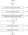
- FIG. 11 is a flowchart illustrating a method of selecting one control parameter from among a plurality of control parameters according to one exemplary embodiment of the present disclosure.
- step S 1102 the processor 124 generates second predictive inspection information corresponding to each of the plurality of second control parameters based on the simulation model.
- the simulation model unit 210 of the processor 124 loads the simulation model from the memory 122, and applies each of the plurality of second parameters to the simulation model, thereby generating the second predictive inspection information on printed states of a plurality of second virtual solder pastes.
- the processor 124 receives second inspection information corresponding to each of the plurality of second control parameters.
- the parameter determination unit 250 of the processor 124 receives the second inspection information corresponding to each of the plurality of second parameters from the inspection device 121 via the communication circuit 123.
- the screen printer 110 prints solder paste on a printed circuit board based on each of the plurality of second control parameters.
- the inspection device 121 inspects the solder paste on each of a plurality of printed circuit boards, thereby generating the second inspection information corresponding to each of the plurality of second control parameters.
- the inspection device 121 transmits the generated second inspection information to the communication circuit 123. Therefore, the parameter determination unit 250 receives the second inspection information corresponding to each of the plurality of second control parameters via the communication circuit 123.
- the processor 124 calculates an average value of differences between the second inspection information and the second predictive inspection information.
- the average value of the differences between the second inspection information and the second predictive inspection information is calculated using Equation 1.
- the parameter determination unit 250 of the processor 124 applies the second inspection information corresponding to each of the plurality of second control parameters to B R in Equation 1, applies the second predictive inspection information corresponding to each of the plurality of second control parameters in R(B P ) in Equation 1, and applies the number of second control parameters to n in Equation 1, thereby calculating the average value of the differences between the second inspection information and the second predictive inspection information.
- step S1108 the processor 124 determines whether the calculated average value of the differences corresponds to a predetermined value.
- the parameter determination unit 250 of the processor 124 determines whether the calculated average value of the differences converges to the predetermined value.
- the predetermined value is 0 but is not necessarily limited thereto.
- the processor 124 selects one control parameter (hereinafter, referred to as an "optimal control parameter") from among the plurality of second control parameters in step S1110.
- the parameter determination unit 250 of the processor 124 selects, as an optimal control parameter, a control parameter (P O1 ) having the highest Z-score from among the plurality of second control parameters (P O1 , P O1 , P O3 , P O4 , P O5 , P O6 , P O7 , P O8 , P L1 , P R1 ).
- step S1112 the processor 124 transmits the selected optimal control parameter to the screen printer 110.
- the parameter determination unit 250 of the processor 124 transmits the optimal control parameters to the screen printer 110 via the communication circuit 123. Therefore, the screen printer 110 prints the solder paste on the printed circuit board based on the optimal control parameter, thereby reducing the occurrence of defects on the printed circuit board.
- steps S908 to S922 in FIG. 9 are performed for each of the plurality of second control parameters.
- the computer-readable recording medium includes any type of recording devices that store data which can be read by a computer system. Examples of the computer-readable recording medium include ROM, RAM, CD-ROM, a magnetic tape, a floppy disk, an optical data storage device, and the like.
- the computer-readable recording medium can be distributed over a network-connected computer system so that the computer-readable codes can be stored and executed in a distributed manner. Further, functional programs, codes, and code segments for implementing the above embodiments can be easily deduced by programmers of the art to which the present disclosure belongs.
- a control parameter for a screen printer may be generated using a regression model that simulates the actual conditions of the screen printer. Therefore, the screen printer may print solder paste on a printed circuit board (bare board) based on the generated control parameter, thereby reducing the occurrence of defects in the solder paste printed on the printed circuit board.
Landscapes
- Engineering & Computer Science (AREA)
- Computer Hardware Design (AREA)
- Theoretical Computer Science (AREA)
- Physics & Mathematics (AREA)
- Evolutionary Computation (AREA)
- Geometry (AREA)
- General Engineering & Computer Science (AREA)
- General Physics & Mathematics (AREA)
- Manufacturing & Machinery (AREA)
- Microelectronics & Electronic Packaging (AREA)
- Mechanical Engineering (AREA)
- Artificial Intelligence (AREA)
- Computer Vision & Pattern Recognition (AREA)
- Medical Informatics (AREA)
- Software Systems (AREA)
- Quality & Reliability (AREA)
- Electric Connection Of Electric Components To Printed Circuits (AREA)
Claims (19)
- Gerät zum Generieren eines Steuerparameters eines Siebdruckers, wobei das Gerät umfasst:
einen Speicher (122), der Folgendes speichert:ein Simulationsmodell, das eingelernt wird, um prädiktive Inspektionsinformationen über gedruckte Zustände einer Vielzahl von virtuellen Lötpasten basierend auf einer Vielzahl von Steuerparametern des Siebdruckers abzuleiten; undmindestens zwei Algorithmen von einem Optimierungsalgorithmus, einem Suchalgorithmus und einem auf maschinellem Lernen basierten Verstärkungslernalgorithmus zum Generieren einer Vielzahl von möglichen Steuerparametern für den Siebdrucker;eine Kommunikationsschaltung (123), die dazu konfiguriert ist, erste Inspektionsinformationen über eine Vielzahl von Lötpasten zu empfangen, wobei die Vielzahl von Lötpasten von dem Siebdrucker basierend auf einem ersten Steuerparameter gedruckt wird; undeinen Prozessor (124), der mit dem Speicher (122) und der Kommunikationsschaltung (123) elektrisch verbunden ist,wobei der Prozessor (124) konfiguriert ist zum:Erzielen von ersten prädiktiven Inspektionsinformationen über einen gedruckten Zustand einer ersten virtuellen Lötpaste durch Anwenden des ersten Steuerparameters auf das Simulationsmodell;Generieren einer Vielzahl von ersten möglichen Steuerparametern basierend auf den ersten prädiktiven Inspektionsinformationen und einem ersten Algorithmus der mindestens zwei Algorithmen;Generieren einer Vielzahl von zweiten möglichen Steuerparametern basierend auf den ersten prädiktiven Inspektionsinformationen und einem zweiten Algorithmus der mindestens zwei Algorithmen, wobei der zweite Algorithmus anders als der erste Algorithmus ist;Bestimmen einer Vielzahl von zweiten Steuerparametern aus der Vielzahl von ersten möglichen Steuerparametern und der Vielzahl von zweiten möglichen Steuerparametern basierend auf den ersten Inspektionsinformationen und den ersten prädiktiven Inspektionsinformationen; undSenden der Vielzahl von zweiten Steuerparametern an den Siebdrucker über die Kommunikationsschaltung (123). - Gerät nach Anspruch 1, wobei jeder von dem ersten Steuerparameter und der Vielzahl von zweiten Steuerparametern mindestens eines von einem Druck, der auf eine Rakel des Siebdruckers ausgeübt wird, einer Bewegungsgeschwindigkeit der Rakel und einer Trenngeschwindigkeit zwischen einer Schablone des Siebdruckers und einem Substrat umfasst.
- Gerät nach Anspruch 1, wobei die ersten Inspektionsinformationen mindestens eines von einem Volumen, einer Fläche, einer Höhe, einer Breite und einer Neigung jeder der Vielzahl von Lötpasten, die von dem Siebdrucker gedruckt werden, umfassen.
- Gerät nach Anspruch 1, wobei die ersten prädiktiven Inspektionsinformationen mindestens eines von einem Volumen, einer Fläche, einer Höhe, einer Breite und einer Neigung der ersten virtuellen Lötpaste umfassen.
- Gerät nach Anspruch 1, wobei der Prozessor (124) ferner konfiguriert ist zum:Berechnen der Differenz zwischen den ersten Inspektionsinformationen und den ersten prädiktiven Inspektionsinformationen;Vergleichen der berechneten Differenz mit dem vorbestimmten Schwellenwert; undAktualisieren des Simulationsmodells unter Verwendung der ersten Inspektionsinformationen und der ersten prädiktiven Inspektionsinformationen, falls bestimmt wird, dass die berechnete Differenz größer als der vorbestimmte Schwellenwert ist.
- Gerät nach Anspruch 5, wobei das Simulationsmodell ein auf maschinellem Lernen basiertes Regressionsmodell umfasst.
- Gerät nach Anspruch 1, wobei der erste Algorithmus der Optimierungsalgorithmus ist und der zweite Algorithmus der Suchalgorithmus ist, und
wobei der Prozessor (124) ferner konfiguriert ist zum:Generieren der Vielzahl von ersten möglichen Steuerparametern durch Anwenden der ersten prädiktiven Inspektionsinformationen auf den Optimierungsalgorithmus; undGenerieren der Vielzahl von zweiten möglichen Steuerparametern durch Anwenden der ersten prädiktiven Inspektionsinformationen auf den Suchalgorithmus. - Gerät nach Anspruch 7, wobei der Prozessor (124) ferner konfiguriert ist zum:Berechnen der Differenz zwischen den ersten Inspektionsinformationen und den ersten prädiktiven Inspektionsinformationen; undVergleichen der berechneten Differenz mit dem vorbestimmten Schwellenwert.
- Gerät nach Anspruch 8, wobei, falls die berechnete Differenz größer als der vorbestimmte Schwellenwert ist, der Prozessor (124) ferner konfiguriert ist zum:Auswählen einer ersten Anzahl von ersten möglichen Steuerparametern aus der Vielzahl von ersten möglichen Steuerparametern;Auswählen einer zweiten Anzahl von zweiten möglichen Steuerparametern aus der Vielzahl von zweiten möglichen Steuerparametern, wobei die zweite Anzahl größer als die erste Anzahl ist; undBestimmen der Vielzahl von zweiten Steuerparametern aus den ausgewählten ersten möglichen Steuerparametern und den ausgewählten zweiten möglichen Steuerparametern.
- Gerät nach Anspruch 8, wobei, falls die berechnete Differenz kleiner oder gleich dem vorbestimmten Schwellenwert ist, der Prozessor (124) ferner konfiguriert ist zum:Auswählen einer ersten Anzahl von ersten möglichen Steuerparametern aus der Vielzahl von ersten möglichen Steuerparametern;Auswählen einer zweiten Anzahl von zweiten möglichen Steuerparametern aus der Vielzahl von zweiten möglichen Steuerparametern, wobei die zweite Anzahl kleiner als die erste Anzahl ist; undBestimmen der Vielzahl von zweiten Steuerparametern aus den ausgewählten ersten möglichen Steuerparametern und den ausgewählten zweiten möglichen Steuerparametern.
- Gerät nach Anspruch 1, wobei der erste Algorithmus der Optimierungsalgorithmus ist und der zweite Algorithmus der auf maschinellem Lernen basierte Verstärkungslernalgorithmus ist, und
wobei der Prozessor (124) ferner konfiguriert ist zum:Generieren der Vielzahl von ersten möglichen Steuerparametern durch Anwenden der ersten prädiktiven Inspektionsinformationen auf den Optimierungsalgorithmus; undGenerieren der Vielzahl von zweiten möglichen Steuerparametern durch Anwenden der ersten Steuerparameter und der ersten prädiktiven Inspektionsinformationen auf den auf maschinellem Lernen basierten Verstärkungslernalgorithmus. - Gerät nach Anspruch 11, wobei der Prozessor (124) ferner konfiguriert ist zum:Berechnen der Differenz zwischen den ersten Inspektionsinformationen und den ersten prädiktiven Inspektionsinformationen; undVergleichen der berechneten Differenz mit dem vorbestimmten Schwellenwert.
- Gerät nach Anspruch 1, wobei der erste Algorithmus der Suchalgorithmus ist und der zweite Algorithmus der auf maschinellem Lernen basierte Verstärkungslernalgorithmus ist, und
wobei der Prozessor (124) ferner konfiguriert ist zum:Generieren der Vielzahl von ersten möglichen Steuerparametern durch Anwenden der ersten prädiktiven Inspektionsinformationen auf den Suchalgorithmus; undGenerieren der Vielzahl von zweiten möglichen Steuerparametern durch Anwenden der ersten Steuerparameter und der ersten prädiktiven Inspektionsinformationen auf den auf maschinellem Lernen basierten Verstärkungslernalgorithmus. - Gerät nach Anspruch 13, wobei der Prozessor (124) konfiguriert ist zum:Berechnen der Differenz zwischen den ersten Inspektionsinformationen und den ersten prädiktiven Inspektionsinformationen; undVergleichen der berechneten Differenz mit dem vorbestimmten Schwellenwert.
- Gerät nach Anspruch 1, wobei der erste Algorithmus der Optimierungsalgorithmus ist und der zweite Algorithmus der Suchalgorithmus ist, und
wobei der Prozessor (124) ferner konfiguriert ist zum:Generieren der Vielzahl von ersten möglichen Steuerparametern durch Anwenden der ersten prädiktiven Inspektionsinformationen auf den Optimierungsalgorithmus;Generieren der Vielzahl von zweiten möglichen Steuerparametern durch Anwenden der ersten prädiktiven Inspektionsinformationen auf den Suchalgorithmus; undGenerieren einer Vielzahl von dritten möglichen Steuerparametern durch Anwenden der ersten Steuerparameter und der ersten prädiktiven Inspektionsinformationen auf den auf maschinellem Lernen basierten Verstärkungslernalgorithmus der mindestens zwei Algorithmen. - Gerät nach Anspruch 15, wobei der Prozessor (124) ferner konfiguriert ist zum:Berechnen der Differenz zwischen den ersten Inspektionsinformationen und den ersten prädiktiven Inspektionsinformationen;Vergleichen der berechneten Differenz mit dem vorbestimmten Schwellenwert; undBestimmen der Vielzahl von zweiten Steuerparametern aus der Vielzahl von ersten möglichen Steuerparametern, der Vielzahl von zweiten möglichen Steuerparametern und der Vielzahl von dritten möglichen Steuerparametern basierend darauf, ob die berechnete Differenz größer als der vorbestimmte Schwellenwert ist.
- Gerät nach Anspruch 1, wobei die Kommunikationsschaltung (123) ferner dazu konfiguriert ist, zweite Inspektionsinformationen zu empfangen, die jedem der Vielzahl von zweiten Steuerparametern entsprechen, und
wobei der Prozessor (124) ferner dazu konfiguriert ist, zweite prädiktive Inspektionsinformationen über die gedruckten Zustände einer Vielzahl von zweiten virtuellen Lötpasten durch Anwenden jedes der Vielzahl von zweiten Steuerparametern auf das Simulationsmodell zu erzielen. - Gerät nach Anspruch 17, wobei der Prozessor (124) ferner konfiguriert ist zum:Berechnen eines Mittelwertes der Differenzen zwischen den zweiten Inspektionsinformationen und den zweiten prädiktiven Inspektionsinformationen;Auswählen eines der Vielzahl von zweiten Steuerparametern, falls der berechnete Mittelwert einem vorbestimmten Wert entspricht; undSenden des ausgewählten zweiten Steuerparameters an den Siebdrucker über die Kommunikationsschaltung (123).
- Verfahren zum Generieren eines Steuerparameters eines Siebdruckers, wobei das Verfahren umfasst:Erzielen von ersten prädiktiven Inspektionsinformationen über einen gedruckten Zustand einer virtuellen Lötpaste durch Anwenden eines ersten Steuerparameters des Siebdruckers auf ein Simulationsmodell, wobei das Simulationsmodell eingelernt wird, um prädiktive Inspektionsinformationen über gedruckte Zustände einer Vielzahl von virtuellen Lötpasten basierend auf einer Vielzahl von Steuerparametern des Siebdruckers abzuleiten;Empfangen von ersten Inspektionsinformationen über gedruckte Zustände einer Vielzahl von Lötpasten, wobei die Vielzahl von Lötpasten von dem Siebdrucker basierend auf dem ersten Steuerparameter gedruckt werden;Generieren einer Vielzahl von ersten möglichen Steuerparametern basierend auf den ersten prädiktiven Inspektionsinformationen und einem ersten Algorithmus von mindestens zwei Algorithmen, wobei die mindestens zwei Algorithmen Algorithmen von einem Optimierungsalgorithmus, einem Suchalgorithmus und einem auf maschinellem Lernen basierten Verstärkungslernalgorithmus zum Generieren einer Vielzahl von möglichen Steuerparametern für den Siebdrucker sind;Generieren einer Vielzahl von zweiten möglichen Steuerparametern basierend auf den ersten prädiktiven Inspektionsinformationen und einem zweiten Algorithmus der mindestens zwei Algorithmen, wobei der zweite Algorithmus anders als der erste Algorithmus ist;Bestimmen einer Vielzahl von zweiten Steuerparametern aus der Vielzahl von ersten möglichen Steuerparametern und der Vielzahl von zweiten möglichen Steuerparametern basierend auf den ersten Inspektionsinformationen und den ersten prädiktiven Inspektionsinformationen; undSenden der Vielzahl von zweiten Steuerparametern an den Siebdrucker.
Applications Claiming Priority (2)
| Application Number | Priority Date | Filing Date | Title |
|---|---|---|---|
| KR20180023093 | 2018-02-26 | ||
| KR1020180154834A KR102167564B1 (ko) | 2018-02-26 | 2018-12-05 | 스크린 프린터의 제어 파라미터를 생성하는 장치 및 방법 |
Publications (3)
| Publication Number | Publication Date |
|---|---|
| EP3530463A1 EP3530463A1 (de) | 2019-08-28 |
| EP3530463B1 true EP3530463B1 (de) | 2024-09-11 |
| EP3530463C0 EP3530463C0 (de) | 2024-09-11 |
Family
ID=64900822
Family Applications (1)
| Application Number | Title | Priority Date | Filing Date |
|---|---|---|---|
| EP18215551.5A Active EP3530463B1 (de) | 2018-02-26 | 2018-12-21 | Vorrichtung und verfahren zur erzeugung eines steuerparameters einer siebdruckmaschine |
Country Status (3)
| Country | Link |
|---|---|
| US (1) | US11379639B2 (de) |
| EP (1) | EP3530463B1 (de) |
| CN (1) | CN110194003B (de) |
Families Citing this family (15)
| Publication number | Priority date | Publication date | Assignee | Title |
|---|---|---|---|---|
| KR20190084167A (ko) * | 2017-12-21 | 2019-07-16 | 주식회사 고영테크놀러지 | 인쇄 회로 기판 검사 장치, 스크린 프린터의 결함 유형 결정 방법 및 컴퓨터 판독 가능한 기록 매체 |
| KR102106349B1 (ko) * | 2017-12-21 | 2020-05-04 | 주식회사 고영테크놀러지 | 인쇄 회로 기판 검사 장치, 솔더 페이스트 이상 감지 방법 및 컴퓨터 판독 가능한 기록 매체 |
| WO2020217510A1 (ja) * | 2019-04-26 | 2020-10-29 | 株式会社Fuji | 印刷パラメータ取得装置および印刷パラメータ取得方法 |
| WO2021081213A1 (en) * | 2019-10-23 | 2021-04-29 | Lam Research Corporation | Determination of recipe for manufacturing semiconductor |
| CN112801328B (zh) * | 2019-11-14 | 2023-10-31 | 富联精密电子(天津)有限公司 | 产品印刷参数设定装置、方法及计算机可读存储介质 |
| US12344019B2 (en) * | 2020-03-31 | 2025-07-01 | Fuji Corporation | Printing control device and printing control method |
| CN111634108B (zh) * | 2020-04-25 | 2020-12-08 | 湖南省美程陶瓷科技有限公司 | 一种磁控管陶瓷金属化涂浆系统及装置 |
| WO2021242062A1 (ko) * | 2020-05-29 | 2021-12-02 | 주식회사 고영테크놀러지 | 솔더 인쇄 장치의 제어 파라미터를 최적화하기 위한 장치 및 방법 |
| CN112261866A (zh) * | 2020-09-28 | 2021-01-22 | 西南电子技术研究所(中国电子科技集团公司第十研究所) | 智能决策pcb质量的smt工艺预测工具 |
| US12275232B1 (en) * | 2022-03-08 | 2025-04-15 | Applied Materials Italia S.R.L. | Method of dispensing paste for a printer using a paste dispensing apparatus and paste dispensing apparatus for dispensing paste for a printer |
| CN118094785A (zh) * | 2022-11-21 | 2024-05-28 | 北京小米移动软件有限公司 | 锡膏印刷参数确定方法、装置及存储介质 |
| DE102023132866A1 (de) * | 2023-11-24 | 2025-05-28 | Manroland Goss Web Systems Gmbh | Verfahren zum Inline-Regeln eines Druckparameters |
| CN117312802B (zh) * | 2023-11-29 | 2024-03-22 | 安徽大学 | 基于人机融合的smt产线关键工艺参数优化方法及存储介质 |
| CN119348289B (zh) * | 2024-12-23 | 2025-04-25 | 远东幕墙(珠海)有限公司 | 彩釉玻璃丝印设备、方法、装置、控制器及介质 |
| CN120716305B (zh) * | 2025-06-17 | 2025-12-05 | 乔科科技(广东)有限公司 | 一种锡膏印刷参数的确定方法及系统 |
Family Cites Families (16)
| Publication number | Priority date | Publication date | Assignee | Title |
|---|---|---|---|---|
| JPH01141739A (ja) | 1987-11-30 | 1989-06-02 | Toshiba Corp | スクリーン印刷装置 |
| JPH0444848A (ja) | 1990-06-12 | 1992-02-14 | Matsushita Electric Ind Co Ltd | スクリーン印刷機 |
| US5751910A (en) * | 1995-05-22 | 1998-05-12 | Eastman Kodak Company | Neural network solder paste inspection system |
| US6587580B1 (en) | 1999-05-06 | 2003-07-01 | Avaya Technology Corp. | Stencil printing process optimization for circuit pack assembly using neural network modeling |
| JP2001347645A (ja) | 2000-06-09 | 2001-12-18 | Dainippon Screen Mfg Co Ltd | 印刷パラメータ決定装置および印刷パラメータ決定方法 |
| JP2004351624A (ja) | 2003-05-27 | 2004-12-16 | Matsushita Electric Ind Co Ltd | クリーム半田のスクリーン印刷装置およびスクリーン印刷方法 |
| US7171897B2 (en) * | 2003-06-05 | 2007-02-06 | Georgia Tech Research Corporation | System and methods for data-driven control of manufacturing processes |
| US20070177789A1 (en) | 2006-01-31 | 2007-08-02 | Jeffrey Harrell | Solder paste inspection system and method |
| JP4893056B2 (ja) | 2006-03-28 | 2012-03-07 | 株式会社日立プラントテクノロジー | スクリーン印刷装置 |
| US20080083816A1 (en) * | 2006-10-04 | 2008-04-10 | Leinbach Glen E | Statistical process control of solder paste stenciling using a replicated solder paste feature distributed across a printed circuit board |
| JP2010008587A (ja) | 2008-06-25 | 2010-01-14 | Canon Inc | キャリブレーション装置 |
| JP5732023B2 (ja) | 2012-10-31 | 2015-06-10 | ヤマハ発動機株式会社 | 半田供給方法、半田供給装置 |
| CN105073423B (zh) | 2013-03-22 | 2017-06-20 | 富士机械制造株式会社 | 丝网印刷机 |
| EP2790473A1 (de) | 2013-04-09 | 2014-10-15 | ASM Assembly Systems GmbH & Co. KG | Optimierung von Parametern zum Drucken von Lötpaste auf ein PCB |
| HUE046480T2 (hu) | 2013-08-19 | 2020-03-30 | Asm Assembly Sys Gmbh & Co Kg | Nyomtatás szabályozási paraméterek megváltoztatása a mért forrasztó kenõcs lerakódásokra alapozva nyomtatott áramköri kártya bizonyos al-területeiben |
| EP2881256A1 (de) | 2013-12-03 | 2015-06-10 | Applied Materials Italia S.R.L. | Vorrichtung und Verfahren für Siebdruck auf einem Substrat |
-
2018
- 2018-12-21 US US16/229,421 patent/US11379639B2/en active Active
- 2018-12-21 EP EP18215551.5A patent/EP3530463B1/de active Active
- 2018-12-24 CN CN201811582073.0A patent/CN110194003B/zh active Active
Also Published As
| Publication number | Publication date |
|---|---|
| CN110194003B (zh) | 2021-08-10 |
| CN110194003A (zh) | 2019-09-03 |
| US20190269017A1 (en) | 2019-08-29 |
| EP3530463A1 (de) | 2019-08-28 |
| US11379639B2 (en) | 2022-07-05 |
| EP3530463C0 (de) | 2024-09-11 |
Similar Documents
| Publication | Publication Date | Title |
|---|---|---|
| EP3530463B1 (de) | Vorrichtung und verfahren zur erzeugung eines steuerparameters einer siebdruckmaschine | |
| EP3501828B1 (de) | Leiterplatteninspektionsvorrichtung, verfahren zur erkennung einer anomalie in lotpaste und computerlesbares aufzeichnungsmedium | |
| JP6871842B2 (ja) | 加工シミュレーションの条件の適正化方法、加工シミュレーション装置、加工シミュレーションシステム及びプログラム | |
| TWI748242B (zh) | 掃描晶圓的系統及方法 | |
| EP3501829B1 (de) | Leiterplattenprüfgerät, verfahren zur bestimmung einer fehlerart einer siebdruckmachine und computerlesbares datenspeichermedium | |
| KR102167564B1 (ko) | 스크린 프린터의 제어 파라미터를 생성하는 장치 및 방법 | |
| CN107094349B (zh) | 印制电路板及其制作方法 | |
| US11635743B2 (en) | Parameters suggestion system of solder paste screen printer including method, device employing method, and non-transitory storage | |
| CN113056742B (zh) | 设计辅助装置、设计辅助方法及机器学习装置 | |
| EP3582599B1 (de) | Vorrichtung zur inspektion von auf einer leiterplatte montierten komponenten, betriebsverfahren dafür und computerlesbares aufzeichnungsmedium | |
| CN111311485B (zh) | 图像处理方法及相关装置 | |
| CN110525073A (zh) | 用于补正丝网印刷机的装置及方法 | |
| CN112183627A (zh) | 生成预测密度图网络的方法和车辆年检标数量检测方法 | |
| CN117015150B (zh) | 一种电路板智能生产工艺、控制系统、装置及存储介质 | |
| US10176288B1 (en) | System and method for placing components in an electronic circuit design | |
| JP7395000B2 (ja) | ソルダー印刷装置の制御パラメータを最適化するための装置及び方法 | |
| US10747198B2 (en) | Solder inspection apparatus and method of generating feedback information of solder inspection apparatus | |
| TW201800177A (zh) | 測長控制裝置、製造系統、測長控制方法以及測長控制程式產品 | |
| CN116702695A (zh) | 一种走线阻抗检测方法、系统、电子设备及可读存储介质 | |
| US20240053278A1 (en) | Method and system for detecting a false error on a component of a board inspected by an aoi machine | |
| JP2007033765A (ja) | パターン製造システム、露光装置、及び露光方法 | |
| KR101444258B1 (ko) | 기판 검사 시의 보상 매트릭스의 유효성 판단 방법 | |
| KR102024809B1 (ko) | 임피던스 매칭을 위한 방법 및 그 전자 장치 | |
| CN113869001B (zh) | 一种pcb模型提取方法、装置、设备及介质 | |
| JP4946753B2 (ja) | 多層回路基板解析システム、多層回路基板解析方法及び多層回路基板解析プログラム |
Legal Events
| Date | Code | Title | Description |
|---|---|---|---|
| PUAI | Public reference made under article 153(3) epc to a published international application that has entered the european phase |
Free format text: ORIGINAL CODE: 0009012 |
|
| STAA | Information on the status of an ep patent application or granted ep patent |
Free format text: STATUS: REQUEST FOR EXAMINATION WAS MADE |
|
| 17P | Request for examination filed |
Effective date: 20190118 |
|
| AK | Designated contracting states |
Kind code of ref document: A1 Designated state(s): AL AT BE BG CH CY CZ DE DK EE ES FI FR GB GR HR HU IE IS IT LI LT LU LV MC MK MT NL NO PL PT RO RS SE SI SK SM TR |
|
| AX | Request for extension of the european patent |
Extension state: BA ME |
|
| RBV | Designated contracting states (corrected) |
Designated state(s): AL AT BE BG CH CY CZ DE DK EE ES FI FR GB GR HR HU IE IS IT LI LT LU LV MC MK MT NL NO PL PT RO RS SE SI SK SM TR |
|
| STAA | Information on the status of an ep patent application or granted ep patent |
Free format text: STATUS: EXAMINATION IS IN PROGRESS |
|
| 17Q | First examination report despatched |
Effective date: 20211221 |
|
| GRAP | Despatch of communication of intention to grant a patent |
Free format text: ORIGINAL CODE: EPIDOSNIGR1 |
|
| STAA | Information on the status of an ep patent application or granted ep patent |
Free format text: STATUS: GRANT OF PATENT IS INTENDED |
|
| INTG | Intention to grant announced |
Effective date: 20240410 |
|
| GRAS | Grant fee paid |
Free format text: ORIGINAL CODE: EPIDOSNIGR3 |
|
| GRAA | (expected) grant |
Free format text: ORIGINAL CODE: 0009210 |
|
| STAA | Information on the status of an ep patent application or granted ep patent |
Free format text: STATUS: THE PATENT HAS BEEN GRANTED |
|
| AK | Designated contracting states |
Kind code of ref document: B1 Designated state(s): AL AT BE BG CH CY CZ DE DK EE ES FI FR GB GR HR HU IE IS IT LI LT LU LV MC MK MT NL NO PL PT RO RS SE SI SK SM TR |
|
| REG | Reference to a national code |
Ref country code: GB Ref legal event code: FG4D |
|
| REG | Reference to a national code |
Ref country code: CH Ref legal event code: EP |
|
| REG | Reference to a national code |
Ref country code: DE Ref legal event code: R096 Ref document number: 602018074202 Country of ref document: DE |
|
| REG | Reference to a national code |
Ref country code: IE Ref legal event code: FG4D |
|
| U01 | Request for unitary effect filed |
Effective date: 20240927 |
|
| U07 | Unitary effect registered |
Designated state(s): AT BE BG DE DK EE FI FR IT LT LU LV MT NL PT RO SE SI Effective date: 20241023 |
|
| PG25 | Lapsed in a contracting state [announced via postgrant information from national office to epo] |
Ref country code: NO Free format text: LAPSE BECAUSE OF FAILURE TO SUBMIT A TRANSLATION OF THE DESCRIPTION OR TO PAY THE FEE WITHIN THE PRESCRIBED TIME-LIMIT Effective date: 20241211 |
|
| PG25 | Lapsed in a contracting state [announced via postgrant information from national office to epo] |
Ref country code: GR Free format text: LAPSE BECAUSE OF FAILURE TO SUBMIT A TRANSLATION OF THE DESCRIPTION OR TO PAY THE FEE WITHIN THE PRESCRIBED TIME-LIMIT Effective date: 20241212 |
|
| PG25 | Lapsed in a contracting state [announced via postgrant information from national office to epo] |
Ref country code: HR Free format text: LAPSE BECAUSE OF FAILURE TO SUBMIT A TRANSLATION OF THE DESCRIPTION OR TO PAY THE FEE WITHIN THE PRESCRIBED TIME-LIMIT Effective date: 20240911 |
|
| PG25 | Lapsed in a contracting state [announced via postgrant information from national office to epo] |
Ref country code: ES Free format text: LAPSE BECAUSE OF FAILURE TO SUBMIT A TRANSLATION OF THE DESCRIPTION OR TO PAY THE FEE WITHIN THE PRESCRIBED TIME-LIMIT Effective date: 20240911 Ref country code: RS Free format text: LAPSE BECAUSE OF FAILURE TO SUBMIT A TRANSLATION OF THE DESCRIPTION OR TO PAY THE FEE WITHIN THE PRESCRIBED TIME-LIMIT Effective date: 20241211 |
|
| PG25 | Lapsed in a contracting state [announced via postgrant information from national office to epo] |
Ref country code: RS Free format text: LAPSE BECAUSE OF FAILURE TO SUBMIT A TRANSLATION OF THE DESCRIPTION OR TO PAY THE FEE WITHIN THE PRESCRIBED TIME-LIMIT Effective date: 20241211 Ref country code: NO Free format text: LAPSE BECAUSE OF FAILURE TO SUBMIT A TRANSLATION OF THE DESCRIPTION OR TO PAY THE FEE WITHIN THE PRESCRIBED TIME-LIMIT Effective date: 20241211 Ref country code: HR Free format text: LAPSE BECAUSE OF FAILURE TO SUBMIT A TRANSLATION OF THE DESCRIPTION OR TO PAY THE FEE WITHIN THE PRESCRIBED TIME-LIMIT Effective date: 20240911 Ref country code: GR Free format text: LAPSE BECAUSE OF FAILURE TO SUBMIT A TRANSLATION OF THE DESCRIPTION OR TO PAY THE FEE WITHIN THE PRESCRIBED TIME-LIMIT Effective date: 20241212 Ref country code: ES Free format text: LAPSE BECAUSE OF FAILURE TO SUBMIT A TRANSLATION OF THE DESCRIPTION OR TO PAY THE FEE WITHIN THE PRESCRIBED TIME-LIMIT Effective date: 20240911 |
|
| U20 | Renewal fee for the european patent with unitary effect paid |
Year of fee payment: 7 Effective date: 20241230 |
|
| PG25 | Lapsed in a contracting state [announced via postgrant information from national office to epo] |
Ref country code: IS Free format text: LAPSE BECAUSE OF FAILURE TO SUBMIT A TRANSLATION OF THE DESCRIPTION OR TO PAY THE FEE WITHIN THE PRESCRIBED TIME-LIMIT Effective date: 20250111 |
|
| PG25 | Lapsed in a contracting state [announced via postgrant information from national office to epo] |
Ref country code: SM Free format text: LAPSE BECAUSE OF FAILURE TO SUBMIT A TRANSLATION OF THE DESCRIPTION OR TO PAY THE FEE WITHIN THE PRESCRIBED TIME-LIMIT Effective date: 20240911 |
|
| PG25 | Lapsed in a contracting state [announced via postgrant information from national office to epo] |
Ref country code: PL Free format text: LAPSE BECAUSE OF FAILURE TO SUBMIT A TRANSLATION OF THE DESCRIPTION OR TO PAY THE FEE WITHIN THE PRESCRIBED TIME-LIMIT Effective date: 20240911 Ref country code: CZ Free format text: LAPSE BECAUSE OF FAILURE TO SUBMIT A TRANSLATION OF THE DESCRIPTION OR TO PAY THE FEE WITHIN THE PRESCRIBED TIME-LIMIT Effective date: 20240911 |
|
| PG25 | Lapsed in a contracting state [announced via postgrant information from national office to epo] |
Ref country code: SK Free format text: LAPSE BECAUSE OF FAILURE TO SUBMIT A TRANSLATION OF THE DESCRIPTION OR TO PAY THE FEE WITHIN THE PRESCRIBED TIME-LIMIT Effective date: 20240911 |
|
| PG25 | Lapsed in a contracting state [announced via postgrant information from national office to epo] |
Ref country code: MC Free format text: LAPSE BECAUSE OF FAILURE TO SUBMIT A TRANSLATION OF THE DESCRIPTION OR TO PAY THE FEE WITHIN THE PRESCRIBED TIME-LIMIT Effective date: 20240911 |
|
| PLBE | No opposition filed within time limit |
Free format text: ORIGINAL CODE: 0009261 |
|
| STAA | Information on the status of an ep patent application or granted ep patent |
Free format text: STATUS: NO OPPOSITION FILED WITHIN TIME LIMIT |
|
| REG | Reference to a national code |
Ref country code: CH Ref legal event code: PL |
|
| 26N | No opposition filed |
Effective date: 20250612 |
|
| GBPC | Gb: european patent ceased through non-payment of renewal fee |
Effective date: 20241221 |
|
| PG25 | Lapsed in a contracting state [announced via postgrant information from national office to epo] |
Ref country code: GB Free format text: LAPSE BECAUSE OF NON-PAYMENT OF DUE FEES Effective date: 20241221 |
|
| PG25 | Lapsed in a contracting state [announced via postgrant information from national office to epo] |
Ref country code: CH Free format text: LAPSE BECAUSE OF NON-PAYMENT OF DUE FEES Effective date: 20241231 |
|
| PG25 | Lapsed in a contracting state [announced via postgrant information from national office to epo] |
Ref country code: IE Free format text: LAPSE BECAUSE OF NON-PAYMENT OF DUE FEES Effective date: 20241221 |
|
| U20 | Renewal fee for the european patent with unitary effect paid |
Year of fee payment: 8 Effective date: 20251219 |