EP3501829B1 - Leiterplattenprüfgerät, verfahren zur bestimmung einer fehlerart einer siebdruckmachine und computerlesbares datenspeichermedium - Google Patents
Leiterplattenprüfgerät, verfahren zur bestimmung einer fehlerart einer siebdruckmachine und computerlesbares datenspeichermedium Download PDFInfo
- Publication number
- EP3501829B1 EP3501829B1 EP17210436.6A EP17210436A EP3501829B1 EP 3501829 B1 EP3501829 B1 EP 3501829B1 EP 17210436 A EP17210436 A EP 17210436A EP 3501829 B1 EP3501829 B1 EP 3501829B1
- Authority
- EP
- European Patent Office
- Prior art keywords
- printed circuit
- anomaly
- circuit board
- screen printer
- detected
- Prior art date
- Legal status (The legal status is an assumption and is not a legal conclusion. Google has not performed a legal analysis and makes no representation as to the accuracy of the status listed.)
- Active
Links
Images


Classifications
-
- B—PERFORMING OPERATIONS; TRANSPORTING
- B41—PRINTING; LINING MACHINES; TYPEWRITERS; STAMPS
- B41F—PRINTING MACHINES OR PRESSES
- B41F15/00—Screen printers
- B41F15/14—Details
- B41F15/16—Printing tables
- B41F15/18—Supports for workpieces
- B41F15/26—Supports for workpieces for articles with flat surfaces
-
- G—PHYSICS
- G01—MEASURING; TESTING
- G01N—INVESTIGATING OR ANALYSING MATERIALS BY DETERMINING THEIR CHEMICAL OR PHYSICAL PROPERTIES
- G01N21/00—Investigating or analysing materials by the use of optical means, i.e. using sub-millimetre waves, infrared, visible or ultraviolet light
- G01N21/84—Systems specially adapted for particular applications
- G01N21/88—Investigating the presence of flaws or contamination
- G01N21/95—Investigating the presence of flaws or contamination characterised by the material or shape of the object to be examined
- G01N21/956—Inspecting patterns on the surface of objects
- G01N21/95607—Inspecting patterns on the surface of objects using a comparative method
-
- B—PERFORMING OPERATIONS; TRANSPORTING
- B41—PRINTING; LINING MACHINES; TYPEWRITERS; STAMPS
- B41F—PRINTING MACHINES OR PRESSES
- B41F33/00—Indicating, counting, warning, control or safety devices
- B41F33/0036—Devices for scanning or checking the printed matter for quality control
-
- B—PERFORMING OPERATIONS; TRANSPORTING
- B41—PRINTING; LINING MACHINES; TYPEWRITERS; STAMPS
- B41F—PRINTING MACHINES OR PRESSES
- B41F33/00—Indicating, counting, warning, control or safety devices
- B41F33/0036—Devices for scanning or checking the printed matter for quality control
- B41F33/0045—Devices for scanning or checking the printed matter for quality control for automatically regulating the ink supply
-
- G—PHYSICS
- G01—MEASURING; TESTING
- G01B—MEASURING LENGTH, THICKNESS OR SIMILAR LINEAR DIMENSIONS; MEASURING ANGLES; MEASURING AREAS; MEASURING IRREGULARITIES OF SURFACES OR CONTOURS
- G01B11/00—Measuring arrangements characterised by the use of optical techniques
- G01B11/24—Measuring arrangements characterised by the use of optical techniques for measuring contours or curvatures
- G01B11/25—Measuring arrangements characterised by the use of optical techniques for measuring contours or curvatures by projecting a pattern, e.g. one or more lines, moiré fringes on the object
-
- G—PHYSICS
- G01—MEASURING; TESTING
- G01N—INVESTIGATING OR ANALYSING MATERIALS BY DETERMINING THEIR CHEMICAL OR PHYSICAL PROPERTIES
- G01N21/00—Investigating or analysing materials by the use of optical means, i.e. using sub-millimetre waves, infrared, visible or ultraviolet light
- G01N21/84—Systems specially adapted for particular applications
- G01N21/88—Investigating the presence of flaws or contamination
- G01N21/95—Investigating the presence of flaws or contamination characterised by the material or shape of the object to be examined
- G01N21/956—Inspecting patterns on the surface of objects
-
- G—PHYSICS
- G06—COMPUTING OR CALCULATING; COUNTING
- G06T—IMAGE DATA PROCESSING OR GENERATION, IN GENERAL
- G06T7/00—Image analysis
- G06T7/0002—Inspection of images, e.g. flaw detection
- G06T7/0004—Industrial image inspection
-
- G—PHYSICS
- G06—COMPUTING OR CALCULATING; COUNTING
- G06T—IMAGE DATA PROCESSING OR GENERATION, IN GENERAL
- G06T7/00—Image analysis
- G06T7/0002—Inspection of images, e.g. flaw detection
- G06T7/0004—Industrial image inspection
- G06T7/001—Industrial image inspection using an image reference approach
-
- H—ELECTRICITY
- H05—ELECTRIC TECHNIQUES NOT OTHERWISE PROVIDED FOR
- H05K—PRINTED CIRCUITS; CASINGS OR CONSTRUCTIONAL DETAILS OF ELECTRIC APPARATUS; MANUFACTURE OF ASSEMBLAGES OF ELECTRICAL COMPONENTS
- H05K13/00—Apparatus or processes specially adapted for manufacturing or adjusting assemblages of electric components
- H05K13/08—Monitoring manufacture of assemblages
-
- G—PHYSICS
- G01—MEASURING; TESTING
- G01N—INVESTIGATING OR ANALYSING MATERIALS BY DETERMINING THEIR CHEMICAL OR PHYSICAL PROPERTIES
- G01N21/00—Investigating or analysing materials by the use of optical means, i.e. using sub-millimetre waves, infrared, visible or ultraviolet light
- G01N21/84—Systems specially adapted for particular applications
- G01N21/88—Investigating the presence of flaws or contamination
- G01N21/8851—Scan or image signal processing specially adapted therefor, e.g. for scan signal adjustment, for detecting different kinds of defects, for compensating for structures, markings, edges
- G01N2021/8854—Grading and classifying of flaws
-
- G—PHYSICS
- G01—MEASURING; TESTING
- G01N—INVESTIGATING OR ANALYSING MATERIALS BY DETERMINING THEIR CHEMICAL OR PHYSICAL PROPERTIES
- G01N21/00—Investigating or analysing materials by the use of optical means, i.e. using sub-millimetre waves, infrared, visible or ultraviolet light
- G01N21/84—Systems specially adapted for particular applications
- G01N21/88—Investigating the presence of flaws or contamination
- G01N21/95—Investigating the presence of flaws or contamination characterised by the material or shape of the object to be examined
- G01N21/956—Inspecting patterns on the surface of objects
- G01N2021/95638—Inspecting patterns on the surface of objects for PCB's
- G01N2021/95646—Soldering
-
- G—PHYSICS
- G06—COMPUTING OR CALCULATING; COUNTING
- G06T—IMAGE DATA PROCESSING OR GENERATION, IN GENERAL
- G06T2207/00—Indexing scheme for image analysis or image enhancement
- G06T2207/20—Special algorithmic details
- G06T2207/20081—Training; Learning
-
- G—PHYSICS
- G06—COMPUTING OR CALCULATING; COUNTING
- G06T—IMAGE DATA PROCESSING OR GENERATION, IN GENERAL
- G06T2207/00—Indexing scheme for image analysis or image enhancement
- G06T2207/20—Special algorithmic details
- G06T2207/20084—Artificial neural networks [ANN]
-
- H—ELECTRICITY
- H05—ELECTRIC TECHNIQUES NOT OTHERWISE PROVIDED FOR
- H05K—PRINTED CIRCUITS; CASINGS OR CONSTRUCTIONAL DETAILS OF ELECTRIC APPARATUS; MANUFACTURE OF ASSEMBLAGES OF ELECTRICAL COMPONENTS
- H05K3/00—Apparatus or processes for manufacturing printed circuits
- H05K3/10—Apparatus or processes for manufacturing printed circuits in which conductive material is applied to the insulating support in such a manner as to form the desired conductive pattern
- H05K3/12—Apparatus or processes for manufacturing printed circuits in which conductive material is applied to the insulating support in such a manner as to form the desired conductive pattern using thick film techniques, e.g. printing techniques to apply the conductive material or similar techniques for applying conductive paste or ink patterns
- H05K3/1216—Apparatus or processes for manufacturing printed circuits in which conductive material is applied to the insulating support in such a manner as to form the desired conductive pattern using thick film techniques, e.g. printing techniques to apply the conductive material or similar techniques for applying conductive paste or ink patterns by screen printing or stencil printing
-
- H—ELECTRICITY
- H05—ELECTRIC TECHNIQUES NOT OTHERWISE PROVIDED FOR
- H05K—PRINTED CIRCUITS; CASINGS OR CONSTRUCTIONAL DETAILS OF ELECTRIC APPARATUS; MANUFACTURE OF ASSEMBLAGES OF ELECTRICAL COMPONENTS
- H05K3/00—Apparatus or processes for manufacturing printed circuits
- H05K3/30—Assembling printed circuits with electric components, e.g. with resistors
- H05K3/32—Assembling printed circuits with electric components, e.g. with resistors electrically connecting electric components or wires to printed circuits
- H05K3/34—Assembling printed circuits with electric components, e.g. with resistors electrically connecting electric components or wires to printed circuits by soldering
- H05K3/3465—Application of solder
- H05K3/3485—Application of solder paste, slurry or powder
Definitions
- the present disclosure relates to a printed circuit board inspection apparatus and, more particularly, to a printed circuit board inspection apparatus for determining a fault type in a screen printer used for printing a printed circuit board.
- the present disclosure is derived from a research carried out as part of the Robot industry convergence core technology of the Ministry of Trade, Industry and Energy [Project No.: 10077589, Project title: Development of SMT optimization system based on machine learning].
- Solder paste is printed on a printed circuit board that is mounted on an electronic device by a screen printer and the process of printing solder paste on a printed circuit board using a screen printer is as follows.
- a screen printer loads a printed circuit board on a table for fixing the printed circuit board and aligns a stencil on the printed circuit board with the apertures of the stencil on the pad of the printed circuit board.
- the screen printer prints the solder paste onto the printed circuit board by depositing the solder paste through the apertures of the stencil using a squeegee. The screen printer then separates the stencil and the printed circuit board from each other.
- the shape of solder pastes printed on a printed circuit board may be inspected through SPI (Solder Paste Inspection).
- SPI is a technique that obtains a 2D or 3D image of the solder pastes printed on the printed circuit board through an optical technology and inspects the shape of solder pastes printed on the printed circuit board from the obtained image.
- WO 2012/164233 and Moganti et al are examples of known printed circuit board inspecting apparatus.
- the present disclosure provides a printed circuit board inspection apparatus that may determine, through the use of a machine-learning based model, fault type of a screen printer associated with an anomaly in a solder paste.
- the present disclosure provides a computer-readable recording medium having a program including executable instructions for enabling a printed circuit board inspection apparatus to determine, through the use of a machine-learning based model, fault type of a screen printer related to an anomaly in a solder paste.
- the present disclosure provides a method for determining a fault type of a screen printer related to an anomaly in a solder paste using a machine-learning based model in a printed circuit board inspection apparatus.
- a printed circuit board inspection apparatus includes a memory configured to store a machine-learning based model that derives at least one value indicating relevance between at least one fault type of a screen printer and an image indicating whether an anomaly associated with a plurality of solder pastes printed on a printed circuit board by a screen printer is detected and a processor electrically connected with the memory, the processor is configured to generate at least one image indicating whether an anomaly associated a plurality of solder pastes printed on a first printed circuit board by a first screen printer is detected, if an anomaly in at least one solder paste of the plurality of solder pastes is detected by using an image of the first printed circuit board, obtain at least one value indicating relevance between at least one fault type of the first printer and the generated at least one image, using the machine-learning based model, and determine a fault type of the first printer associated with the at least one solder paste in which the anomaly is detected from at least one fault type of the first printer, based on the obtained at least one value.
- the processor detects whether the anomaly in at least one solder paste of the plurality of solder pastes occurred using first measured information about the plurality of solder pastes obtained from the image of the first printed circuit board.
- the first measured information includes at least one of a volume, an area, a height, a shape, or a position of a solder paste.
- the memory further stores second measured information about a plurality of solder pastes respectively printed on a plurality of second printed circuit boards that have been inspected by the apparatus before the first printed circuit board is inspected, and the processor detects whether the anomaly in at least one solder paste of the plurality of solder pastes occurred by using the first measured information and the second measured information.
- the second measured information is generated by combining sequentially the measured information about the plurality of solder pastes respectively printed on the plurality of second printed circuit boards in accordance with an inspection sequence of the plurality of second printed circuit boards.
- the processor determines changes in the measured information about the plurality of solder pastes respectively printed on the plurality of second printed circuit boards according to the inspection sequence of the plurality of second printed circuit boards on the basis of the second measured information, and determines the fault type associated with at least one solder paste in which the anomaly is detected from at least one fault type based on the determined changes in the measured information.
- the at least one fault type includes a fault of a squeegee blade, a fault in fixing of the squeegee blade, a fault of a support part, a fault of a table, a fault due to poor setting of a grid lock, a fault due to negligence and poor kneading of a solder paste, a fault due to a deficit of a solder paste, and a fault due to poor contact of a stencil.
- the machine-learning based model is a CNN (Convolution Neural Network) model.
- the processor performs learning on the machine-learning based model through a plurality of images indicating whether an anomaly associated with a plurality of solder pastes printed on a printed circuit board is detected, classified in accordance with at least one fault type.
- the processor performs learning on the machine-learning based model through the generated at least one image, after the fault type associated with the at least one solder paste in which the anomaly is detected is determined.
- the processor determines a fault type corresponding to value over a predetermined threshold of the at least one obtained value as the fault type associated with the at least one solder paste in which the anomaly is detected.
- An embodiment of the present disclosure provides a non-transitory computer-readable recording medium having a program to be executed by a computer, wherein the program includes executable instructions that instruct a processor, when the program is executed by the processor, to perform generating at least one images indicating whether an anomaly associated with a plurality of solder pastes printed on a first printed circuit board is detected, if an anomaly in at least one solder paste of the plurality of solder pastes is detected by using an image of the first printed circuit board, obtaining at least one value indicating relevance between at least one fault type and the generated at least one image, using a machine-learning based model that derives at least one value indicating relevance between at least one fault type of the screen printer and an image indicating whether an anomaly in a plurality of solder pastes printed on a printed circuit board is detected and determining a fault type associated with the at least one solder paste in which the anomaly is detected from at least one fault type, based on the obtained at least one value.
- the executable instructions further instruct the processor to perform detecting whether the anomaly in at least one solder paste of the plurality of solder pastes occurred, using first measured information about the plurality of solder pastes obtained from the image of the first printed circuit board.
- the first measured information includes at least one of a volume, an area, a height, a shape, or a position of a solder paste.
- the detecting whether the anomaly in at least one solder paste of the plurality of solder pastes occurred includes detecting whether the anomaly in at least one solder paste of the plurality of solder pastes occurred by using the first measured information and second measured information, wherein the second measured information is generated by combining sequentially the measured information about a plurality of solder pastes respectively printed on a plurality of second printed circuit board in accordance with inspection sequence of the plurality of second printed circuit boards that have been inspected by a printed circuit board inspection apparatus before the first printed circuit board is inspected.
- the machine-learning based model is a CNN (Convolution Neural Network) model.
- the executable instructions further instruct the processor to perform learning on the machine-learning based model through a plurality of images indicating whether an anomaly in a plurality of solder pastes printed on a printed circuit board is detected, classified in accordance with at least one fault type.
- the determining fault type includes determining a fault type corresponding to value over a predetermined threshold of the obtained at least one value as the fault types associated with the at least one solder paste in which the anomaly is detected.
- An embodiment of the present disclosure provides a method for determining a fault type of a screen printer by a printed circuit board inspection apparatus, the method includes: generating at least one images indicating whether an anomaly associated with a plurality of solder pastes printed on a first printed circuit board is detected, if an anomaly in at least one solder paste of the plurality of solder pastes is detected by using an image of the first printed circuit board, obtaining at least one value indicating relevance between at least one fault type and the generated at least one image, using a machine-learning based model that derives at least one value indicating relevance between at least one fault type of the screen printer and an image indicating whether an anomaly associated with a plurality of solder pastes printed on a printed circuit board is detected and determining fault type associated with the at least one solder paste in which the anomaly is detected from at least one fault type, based on the obtained at least one value.
- a printed circuit board inspection apparatus may detect a fault type associated with the at least one solder paste in which an anomaly is detected from at least one fault type of a screen printer, using at least one image indicating whether an anomaly associated with a plurality of solder pastes printed on a first printed circuit board is detected. Accordingly, it is possible to quickly determine a fault type of the screen printer that causes an anomaly and make appropriate corrections.
- Embodiments described herein are provided as examples for explaining the present disclosure.
- the scope of the present disclosure is not limited to the following embodiments or the detailed description of the embodiments.
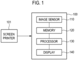
- FIG. 1 is a block diagram of a printed circuit board inspection apparatus according to various embodiments of the present disclosure.
- a printed circuit board inspection apparatus 100 may include an image sensor 110, a memory 120, and a processor 130. Further, the printed circuit board inspection apparatus 100 may further include a display 140 for outputting a result processed by the processor 130 and another output device (not shown) or a communication circuit (not shown) for transmitting the processed result to another electronic device.
- the image sensor 110, memory 120, processor 130, and display 140 are electrically connected to each other, so they may transmit/receive signals.
- the image sensor 110 may obtain an image of a printed circuit board printed with a plurality of solder pastes by a screen printer 101.
- the image obtained by the image sensor 110 may be a 2D or 3D image of the printed circuit board.
- the image of the printed circuit board obtained by the image sensor 110 may be used to measure information about the solder pastes printed on the printed circuit board.
- information including at least one of the volume, area, height, shape, and position of the solder pastes printed on the printed circuit board may be measured using the image of the printed circuit board.
- these examples are provided just for explanation and the information is not limited thereto, and various information that indicates the characteristics of the solder pastes may be measured from the image of the printed circuit board.
- 'measured information' may be defined as information about a plurality of pastes measured from an image of a printed circuit board.
- the memory 120 may store a machine-learning based model.
- the machine-learning based model may be learned to derive at least one value indicating relevance between at least one fault type of the screen printer 101 and an image indicating whether an anomaly in a plurality of solder pastes printed on a printed circuit board is detected.
- the machine-learning based model may be a CNN (Convolution Neutral Network) model.
- the machine-learning based model may be stored in a memory of an electronic apparatus (ex, external server, etc.) connected to the printed circuit board inspection apparatus 100. In this case, the printed circuit board inspection apparatus 100 may communicate information for determining the fault type associated with the at least one solder paste in which the anomaly is detected with the electronic apparatus connected to the printed circuit board inspection apparatus 100.
- the at least one value indicating relevance between the at least one fault type and the image indicating whether an anomaly in a plurality of solder pastes printed on a printed circuit board is detected may be probability value.
- the at least one value may indicates that the image indicating whether an anomaly in a plurality of solder pastes printed on a printed circuit board is detected may have relevance of a% with a first fault type of the screen printer 101 and relevance of b% with a second fault type of the screen printer 101.
- this example is provided only for explanation and the present disclosure is not limited thereto, and various values that may indicate relevance may be used.
- At least one fault type of the screen printer 101 may be at least one fault type that may cause a fault in a solder paste printed on a printed circuit board, of various fault types that may occurr in the screen printer 101.
- the at least one fault type of the screen printer 101 may include at least one of a fault of a squeegee blade of the screen printer 101, a fault in fixing of the squeegee blade (for example, a fault in fixing of a screw for fixing the squeegee blade), a fault of a support of the screen printer 101, a fault of a table of the screen printer 101, a fault due to poor setting of a grid lock when the grid lock is used as the support, a fault due to the state of a solder paste fed in the screen printer 101, for example, negligence of the solder paste and poor kneading of the solder paste, a fault due to a deficit of a solder paste fed in the screen printer 101, and a fault due to poor contact of
- the machine-learning based model stored in the memory 120 may be learned from a plurality of images indicating whether an anomaly in a plurality of solder pastes printed on a printed circuit board is detected, classified in accordance with the at least one fault type of the screen printer 101.
- the machine-learning based model may be learned from a plurality of first images indicating whether an anomaly in a plurality of solder pastes printed on a printed circuit board is detected, classified into a first fault type of the screen printer 101 and a plurality of second images indicating whether an anomaly in a plurality of solder pastes printed on a printed circuit board is detected, classified into a second fault type of the screen printer 101.
- the machine-learning based model may output a value indicating the relevance between the input image and at least one of the first fault type and second fault type.
- the processor 130 may detect whether an anomaly in at least one solder paste of the plurality of solder pastes printed on a first printed circuit board occurred, using an image of the first printed circuit board obtained by the image sensor 110.
- the first printed circuit board may be a printed circuit board that is printed with a plurality of solder pastes by the screen printer 101 and is then conveyed to the printed circuit board inspection apparatus 100 as an object to be inspected.
- the processor 130 may generate first measured information about the plurality of solder pastes using the image of the first printed circuit board.
- the processor 130 may detect whether an anomaly in the at least one solder paste of the plurality of solder pastes occurred using the generated first measured information.
- the memory 120 may store second measured information about a plurality of solder pastes respectively printed on a plurality of second printed circuit boards that have been inspected before the first printed circuit board is inspected.
- the processor 130 may store second measured information generated in the process of inspecting the plurality of second printed circuit boards in the memory 120.
- the second measured information may be used for detecting whether an anomaly in the plurality of solder pastes printed on the first printed circuit board occurred after the second printed circuit boards are inspected.
- the second measured information may be generated by combining sequentially the measured information about the solder pastes printed on the plurality of the second printed circuit boards in accordance with the inspection sequence of the plurality of second printed circuit boards. A detailed method of creating the second measured information will be described below.
- the processor 130 may detect whether an anomaly in at least one solder paste of the plurality of solder pastes printed on a first printed circuit board occurred by using the first measured information and the second measured information. For example, the processor 130 may determine the difference between the first measured information and the second measured information by comparing the first measured information and the second measured information with each other, and when the determined difference is outside a predetermined range, the processor 130 may detect that, in the plurality of solder pastes printed on the first printed circuit board, an anomaly in at least one solder paste outside the predetermined range occurred.
- the processor 130 may determine the difference between the first measured information and the second measured information, and when the determined difference is inside the predetermined range, the processor 130 may detect that an anomaly in the plurality of solder pastes printed on the first printed circuit board has not occurred.
- the processor 130 may detect whether an anomaly in at least one solder paste occurred by using the first measured information and the second measured information in various ways such as statistically analyzing the first measured information and the second measured information according to the inspection sequence of a plurality of printed circuit boards.
- the processor 130 may determine a change in the measured information about the solder pastes printed on the plurality of second printed circuit boards according to the inspection sequence of the second printed circuit boards on the basis of the second measured information. For example, the processor 130 may determine differences in the measured information about the solder pastes printed on the plurality of second printed circuit boards and determine how the differences change in accordance with the inspection sequence of the second printed circuit boards.
- the processor 130 may determine the fault types associated with the at least one solder paste in which the anomaly is detected of the at least one fault type of the screen printer 101 on the basis of the determined changes in the measured information about the solder pastes. For example, when an anomaly in at least one solder paste of the plurality of solder pastes is detected, the processor 130 may determine fault type associated with the at least one solder paste in which the anomaly is detected on the basis of the detected changes in the measured information about the solder pastes.
- the processor 130 may generate at least one image indicating whether an anomaly associated with the plurality of solder pastes is detected.
- the processor 130 may generate at least one image indicating whether an anomaly associated with the plurality of solder pastes is detected.
- At least one image indicating whether an anomaly associated with a plurality of solder pastes printed is detected may be at least one of an image indicating whether an anomaly associated with all of the plurality of solder pastes printed on a first printed circuit board is detected, an image indicating whether an excessive supply anomaly in a plurality of solder pastes printed on a first printed circuit board is detected, and an image indicating an insufficient supply anomaly associated with a plurality of solder pastes printed on a first printed circuit board is detected.
- the processor 130 may generate an image indicating whether an anomaly associated with all of a plurality of solder pastes printed on a first printed circuit board is detected, and may generate an image indicating whether an excessive supply anomaly in a plurality of solder pastes printed on a first printed circuit board is detected, and an image indicating an insufficient supply anomaly associated with a plurality of solder pastes printed on a first printed circuit board is detected.
- this example is provided just for explanation and the present invention is not limited thereto, and the processor 130 may generate images used for learning the machine-learning based model.
- the processor 130 may obtain at least one value indicating relevance between the at least one fault type of the screen printer 101 and at least one generated image, using the machine-learning based model stored in the memory 120.
- the processor 130 may determine the fault type associated with the at least one solder paste in which the anomaly is detected from at least one fault types based on the obtained at least one value.
- the processor 130 may output information about the determined fault type through the display 140 or another output device (not shown). Further, the processor 130 may transmit the information about the determined fault type to another electronic device through a communication circuit (not shown) included in the printed circuit board inspection apparatus 100.
- the processor 130 may determine the fault type corresponding to a value over a predetermined threshold of the obtained at least one value as the fault type associated with the at least one solder paste in which the anomaly is detected.
- the processor 130 may determine the fault type, which is associated with the at least one solder paste in which the anomaly is detected, of the screen printer 101 and then perform learning on the machine-learning based model through the at least one generated image. As described above, the processor 130 may more exactly determine the fault type, which is associated with the at least one solder paste in which the anomaly is detected, of the screen printer 101, by performing learning on the machine-learning based model every time printed circuit boards are inspected.
- FIG. 2 is a flowchart of a method of determining a fault type associated with at least one solder paste in which an anomaly is detected according to various embodiments of the present disclosure.
- Process steps, method steps, and algorithms are sequentially illustrated sequentially in the flowcharts of FIGS. 2 , 3 and 5 , but the processes, methods, and algorithms may be performed in any predetermined sequence as appropriate.
- the steps of processes, methods, and algorithms described in various embodiments of the present disclosure are not necessarily performed in the sequence described herein.
- steps are described as being non-simultaneously performed, they may be simultaneously performed in another embodiment.
- examples of processes shown in the drawings do not mean that the exemplary processes exclude other changes and modifications, do not mean that some of the exemplary processes or the steps of the processes are necessary in one of various embodiments of the present disclosure, and do not mean that the exemplary processes are preferable.
- the processor 130 of the printed circuit board inspection apparatus 100 may obtain an image of a first printed circuit board printed with a plurality of solder pastes through the image sensor 110.
- the processor 130 may further obtain measured information about the solder pastes using the obtained image.
- the measured information about the solder pastes may include at least one of the volume, area, height, shape, and position of the plurality of solder pastes.
- step S220 if an anomaly in at least one solder paste of the plurality of solder pastes printed on the first printed circuit board is detected by using an image of the first printed circuit board, the processor 130 may generate at least one image indicating whether an anomaly associated with a plurality of solder pastes printed on a first printed circuit board is detected, using the obtained image of the first printed circuit board.
- the processor 130 may generate at least one image indicating whether an anomaly associated with the plurality of solder pastes printed on a first printed circuit board is detected.
- the processor 130 may obtain at least one value indicating relevance between at least one fault type of the screen printer 101 and the at least one generated image, using the machine-learning based model stored in the memory 120.
- the machine-learning based model may extract characteristics of the at least one generated image and derive at least one value indicating relevance between the fault types of the screen printer 101 and the one or more generated images based on the extracted characteristics.
- the processor 130 may determine the fault types associated with the at least one solder paste in which the anomaly is detected from the at least one fault type of the screen printer 101 based on the obtained at least one value.
- the processor 130 may determine a fault type corresponding to value over a predetermined threshold of the obtained at least one value as the fault type associated with the at least one solder paste in which the anomaly is detected.
- the processor 130 may detect a plurality of fault types corresponding to upper n values based on the magnitudes of the obtained values as fault types associated with the at least one solder paste in which the anomaly is detected.
- the number corresponding to n may depend on the situation.
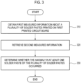
- FIG. 3 is a flowchart of a method of detecting an anomaly in at least one solder paste printed on a printed circuit board, according to various embodiments of the present disclosure.
- the processor 130 of the printed circuit board inspection apparatus 100 may obtain first measured information about a plurality of solder pastes printed on the first printed circuit board using an image of the first printed circuit board obtained by the image sensor 110.
- the processor 130 may measure information about at least one of the volume, area, height, shape, and position of the plurality of solder pastes from an image and generate first measured information on the basis of the measured information.
- the processor 130 may retrieve second measured information in the memory(120). Alternatively, the processor may receive the second measured information form an external server.
- the second measured information may be measured information about a plurality of solder pastes printed on a plurality of second printed circuit boards that have been inspected by the printed circuit board inspection apparatus 100 before the first printed circuit board is inspected.
- the processor 130 may measure information about at least one of the volume, area, height, shape, and position of the plurality of solder pastes printed on the plurality of second printed circuit boards from images of the second printed circuit boards in the process of inspecting the second printed circuit boards, and generate the second measured information on the basis of the measured information.
- the processor 130 may store the generated second measured information in the memory 120 or store the generated second measurement information in the external server. Further, the processor 130 may update the second measured information by adding the first measured information to the second measured information after the first printed circuit board is inspected.
- the processor 130 may determine whether the anomaly in at least one solder paste of the plurality of solder pastes occurred by using the first measured information and the second measured information. For example, the processor 130 may determine the difference between the first measured information and the second measured information by comparing the first measured information and the second measured information each other, and when the determined difference is outside a predetermined range, the processor 130 may detect that, in the plurality of solder pastes printed on the first printed circuit board, an anomaly in at least one solder paste outside the predetermined range occurred. Further, the processor 130 may determine the difference between the first measured information and the second measured information, and when the determined difference is inside the predetermined range, the processor 130 may detect that an anomaly in the plurality of solder pastes printed on the first printed circuit board has not occurred.
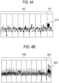
- FIGS. 4A to 4C indicate graphs indicating first measured information and second measured information and a printed circuit board printed with a solder paste having a problem, according to various embodiments of the present disclosure.
- second measured information 412, 422, and 432 may be generated by combining sequentially the measured information about a plurality of solder pastes respectively printed on a plurality of second printed circuit boards according to an inspection sequence by the printed circuit board inspection apparatus 100.
- the measurement information may include measured information for each of a plurality of solder pastes printed on each of the plurality second printed circuit boards or the first printed circuit board.
- first measured information 411, 421, and 431 and second measured information 412, 422, and 432 may include measured information about a plurality of solder pastes printed on one printed circuit board arranged in accordance with area ratios of pads on which the solder pastes are printed.
- this is provided juts as an example and the present disclosure is not limited thereto, and the measured information about a plurality of solder pastes included in the first measured information 411, 421, and 431 and the second measured information 412, 422, and 432 may be arranged in accordance with the ID information, the aspect ratios of the pads on which the solder pastes are printed or an inspection order of each of the plurality of solder pastes or may be randomly distributed without a specific reference.
- the processor 130 of the printed circuit board inspection apparatus 100 may compare the first measured information 411, 421, and 431 and the second measured information 412, 422, and 432 with each other.
- the processor 130 may determine differences between the first measured information 411, 421, and 431 and the second measured information 412, 422, and 432 by comparing the first measured information 411, 421, and 431 and the second measured information 412, 422, and 432 with each other. Further, the processor 130 may determine parts 413, 423, and 433 of the determined differences that are outside a predetermined range.
- the processor 130 may determine that an anomaly in at least one solder paste corresponding to the determined parts 413, 423, and 433 outside the predetermined range occurred.
- the processor 130 may update the second measured information 412, 422, and 432 by adding the first measured information 411, 421, and 431 to the second measured information 412, 422, and 432, after inspection on the first printed circuit board is finished. For example, the processor 130 may update the second measured information 412, 422, and 432 only when an anomaly in the solder pastes printed on the first circuit board does not occurred. Alternatively, the processor 130 may update the second measured information 412, 422, and 432 even if an anomaly at least one the solder paste printed on the first circuit board occurred.
- FIG. 5 is a flowchart of a method of determining a fault type of a screen printer that are associated with at least one solder paste in which an anomaly is detected, according to various embodiments of the present disclosure
- the processor 130 may determine fault type associated with the at least one solder paste in which an anomaly is detected of the at least one fault type of the screen printer 101 based on the determined changes in the measured information about the solder paste. For example, if an anomaly in at least one solder paste of the plurality of solder pastes is detected, the processor 130 may determine fault type associated with the at least one solder paste in which the anomaly is detected on the basis of the determined changes in the measured information about the solder pastes, before using the machine-learning based model. Alternatively, the processor 130 may simultaneously perform determination of the fault type through the machine-learning based model and determination of fault types on the basis of the changes in the measured information. In this case, the processor 130 may finally determine the fault types associated with the at least one solder paste in which the anomaly is detected, using the results of determination of the fault type through the machine-learning based model and determination of fault types on the basis of the changes in the measured information.
- the processor 130 may output information about the determined fault type through the display 140 or another output device. Further, the processor 130 may transmit information about the determined fault type to another electronic device.
- FIG. 6 is a graph indicating second measured information and a plurality of information decomposed from the second measured information, according to various embodiments of the present disclosure.
- second measured information may be generated by combining sequentially measured information about a plurality of solder pastes printed on a plurality of second printed circuit boards in accordance with the inspection sequence by the printed circuit board inspection apparatus 100.
- second measured information 610 may be generated by combining sequentially measured information about a plurality of solder pastes printed on the first to ninth PCBs according to the inspection sequence of the first to ninth PCBs.
- the second measured information 610 may be used for detecting whether an anomaly in a plurality of solder pastes printed on a printed circuit board, that is carried and inspected later by the printed circuit board inspection apparatus 100, occurred.
- the measured information about the solder pastes printed on the first to ninth PCBs may be arranged on the basis of information about a plurality of pads on which the solder paste is printed.
- the measured information about the solder pastes printed on the first to ninth PCBs may be combined sequentially according to the inspection sequence of the first to ninth PCBs.
- measured information about the solder pastes printed on the first to ninth PCBs may be arranged on the basis of the characteristics of the pads (for example, the area ratio, aspect ratio, position cluster group ID, or pad ID).
- the characteristics of the pads on the printed circuit boards may be different, so the second measured information 610 may be decomposed into, as in the following Equation 1, period information 620, tendency information 630, conditional distribution information 640, average movement tendency information 650, and error information 660.
- Yt St + Tt + ht + ⁇ t + Et
- Yt the second measured information 610
- St the period information 620
- It is the tendency information 630
- ht is the conditional distribution information 640
- ⁇ t is the average movement tendency information 650
- Et is the error information 660.
- the period information 620 may be the same in the first to ninth PCBs and the tendency information 630 may indicate the tendency of the measured information about the solder pastes printed on the first to ninth PCBs.
- the conditional distribution information 640 may be information indicating fluctuation according to the different characteristics of the pads and the average movement tendency information 650 may be information indicating the tendency of the measured information about solder pastes having different average values due to the different characteristics of the pads.
- the error information 660 may be noise except for the period information 620, tendency information 630, conditional distribution information 640, and average movement tendency information 650 in the second measured information 610.
- the second measured information 610 by decomposing the second measured information 610 in consideration of the different characteristics of the pads on the printed circuit boards, it is possible to more exactly analyze the second measured information 610 generated by combining sequentially the measured information about the solder pastes printed on the first to ninth PCBs according to the inspection sequence of the first to ninth PCBs. Further, it is possible to determine a fault in the screen printer 101 by determining changes in the measured information about the solder pastes printed on the first to ninth PCBs according to the analysis result.
- the first measured information about the solder pastes printed on the first printed circuit board may also be decomposed into period information, tendency information, conditional distribution information, average movement tendency information, and error information in accordance with the characteristics of a plurality of pads on the first printed circuit board.
- the processor 130 of the printed circuit board inspection apparatus 100 may compare the period information, tendency information, conditional distribution information, average movement tendency information, and error information decomposed from the first measured information with the period information 620, tendency information 630, conditional distribution information 640, average movement tendency information 650, and error information 660 decomposed from the second measured information 610.
- the processor 130 may detect whether the anomaly in at least one solder paste of the plurality of solder pastes occurred using the comparison result.
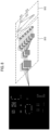
- FIGS. 7A and 7B illustrate images indicating whether an anomaly in a plurality of solder pastes printed on a printed circuit board is detected according to various embodiments of the present disclosure.
- the processor 130 of the printed circuit board inspection apparatus 100 may generate at least one image 720, 730, and 740 used for learning of the machine-learning based model from an image 710 of a first printed circuit board.
- the processor 130 may acquire at least one value indicating the relevance between the at least one fault type of the screen printer 101 and the generated at least one image, using the learned machine-learning based model.
- the processor 130 may generate the image 720 indicating whether an anomaly associated with all of a plurality of solder pastes printed on a first printed circuit board is detected. For example, at least one solder paste of which an anomaly is not detected may be marked as black and at least one solder paste of which the anomaly is detected may be marked as white. In addition, whether an anomaly in a plurality of solder pastes may be indicated by a value of 0 or 1. For example, a pixel value corresponding to at least one solder paste of which an anomaly is not detected may be set to 0 and a pixel value corresponding to at least one solder paste of which the anomaly is detected may be set to 1.
- the processor 130 may generate the image 730 and the image 740.
- the generated image 730 whether an excessive supply anomaly in a plurality of solder pastes printed on a first printed circuit board is detected is displayed.
- the generated image 740 whether an insufficient supply anomaly in a plurality of solder pastes printed on a first printed circuit board is detected is displayed.
- the processor 130 may generate one or more other images different from the images described above.
- FIG. 8 is a conceptual diagram indicating a machine-learning based model according to various embodiments of the present disclosure.
- the processor 130 of the printed circuit board inspection apparatus 100 may perform learning on the machine-learning based model through a plurality of images indicating whether an anomaly in a plurality of solder pastes printed on a printed circuit board is detected, classified in accordance with at least one fault type of the screen printer 101.
- a CNN model that is one of the machine-learning based models is exemplified in the following description for the convenience of description, but the present disclosure is not limited thereto and various machine-learning based models may be used.
- images that are used to perform learning on the CNN model at least one of an image indicating whether an anomaly associated with all of a plurality of solder pastes printed on a first printed circuit board is detected, an images indicating whether an excessive supply anomaly in a plurality of solder pastes printed on a first printed circuit board is detected, and an image indicating an insufficient supply anomaly in a plurality of solder pastes printed on a first printed circuit board is detected may be used.
- characteristic extraction layer 810 of CNN including one or more convolution layers and one or more pooling layers may extract the characteristics of the image indicating whether an anomaly in a plurality of solder pastes printed on a first printed circuit board is detected.
- the characteristic extraction layer 810 may use a 3x3 or 5x5 filter to extract the characteristics of an image.
- the coefficients of the 3x3 or 5x5 filter may be determined in the process of performing learning on the CNN through a plurality of images indicating whether an anomaly in a plurality of solder pastes printed on a first printed circuit board is detected, classified in accordance with at least on of fault type of the screen printer 101.
- a classifier 820 that is a fully connected layer of the CNN may classify images indicating whether an anomaly in a plurality of solder pastes printed on a first printed circuit board is detected, using the characteristics extracted by the characteristic extraction layer 810.
- the classification result acquired by the classifier 820 may include values indicating the relevance between an image indicating whether an anomaly in a plurality of solder pastes printed on a first printed circuit board is detected and the at least one fault type.
- the method may be implemented by computer-readable codes on a computer-readable recording medium.
- the computer-readable recording medium includes all kinds of recording devices that store data that may be read by a computer system.
- the computer-readable recording medium may include a ROM, a RAM, a CD-ROM, an optical data storage etc.
- the computer-readable recording mediums may be distributed to computer systems that are connected through a network and may store and execute codes that may be divisionally read by computers. Further, functional programs, codes, and code segments for implementing the embodiments may be easily inferred by programmers in the art.
Landscapes
- Engineering & Computer Science (AREA)
- Quality & Reliability (AREA)
- Physics & Mathematics (AREA)
- General Physics & Mathematics (AREA)
- Computer Vision & Pattern Recognition (AREA)
- Theoretical Computer Science (AREA)
- Chemical & Material Sciences (AREA)
- Pathology (AREA)
- Health & Medical Sciences (AREA)
- Life Sciences & Earth Sciences (AREA)
- Analytical Chemistry (AREA)
- Biochemistry (AREA)
- General Health & Medical Sciences (AREA)
- Immunology (AREA)
- Mechanical Engineering (AREA)
- Manufacturing & Machinery (AREA)
- Operations Research (AREA)
- Microelectronics & Electronic Packaging (AREA)
- Electric Connection Of Electric Components To Printed Circuits (AREA)
- Investigating Materials By The Use Of Optical Means Adapted For Particular Applications (AREA)
Claims (15)
- Leiterplatteninspektionsvorrichtung (100), umfassend:einen Speicher (120), der dafür konfiguriert ist, ein maschinenlernbasiertes Modell zu speichern, das mindestens einen Wert ableitet, der eine Relevanz zwischen mindestens einem Fehlertyp eines Siebdruckers und einem Bild angibt, das angibt, ob eine Anomalie im Zusammenhang mit mehreren Lotpasten, die durch den Siebdrucker auf eine Leiterplatte gedruckt wurden, detektiert wird; undeinen Prozessor (130), der elektrisch mit dem Speicher (120) verbunden ist,wobei der Prozessor (130) konfiguriert ist zum:Generieren mindestens eines Bildes, das angibt, ob eine Anomalie im Zusammenhang mit mehreren Lotpasten, die durch den Siebdrucker auf eine erste Leiterplatte gedruckt wurden, detektiert wird, falls eine Anomalie in mindestens einer Lotpaste der mehreren Lotpasten unter Verwendung eines Bildes der ersten Leiterplatte detektiert wird,Erhalten mindestens eines Wertes, der eine Relevanz zwischen mindestens einem Fehlertyp des Siebdruckers und dem generierten mindestens einen Bild angibt, unter Verwendung des maschinenlernbasierten Modells, undBestimmen eines Fehlertyps des Siebdruckers im Zusammenhang mit der mindestens einen Lotpaste, in der die Anomalie detektiert wird, aus dem mindestens einem Fehlertyp des Siebdruckers auf der Grundlage des erhaltenen mindestens einen Wertes,wobei das mindestens eine Bild zwischen mindestens einer ersten Lotpaste, in der die Anomalie detektiert wird, und mindestens einer zweiten Lotpaste, in der die Anomalie nicht detektiert wird, unterscheidet.
- Vorrichtung nach Anspruch 1, wobei der Prozessor (130) unter Verwendung erster gemessener Informationen über die mehreren Lotpasten, die aus dem Bild der ersten Leiterplatte erhalten wurden, detektiert, ob die Anomalie in der mindestens einen Lotpaste der mehreren Lotpasten aufgetreten ist.
- Vorrichtung nach Anspruch 2, wobei die ersten gemessenen Informationen mindestens eines von einem Volumen, einer Fläche, einer Höhe, einer Form und einer Position einer Lotpaste enthalten.
- Vorrichtung nach Anspruch 3, wobei der Speicher (120) des Weiteren zweite gemessene Informationen über mehrere Lotpasten speichert, die jeweils durch den Siebdrucker auf mehrere zweite Leiterplatten gedruckt wurden, wobei die mehreren zweiten Leiterplatten durch die Leiterplatteninspektionsvorrichtung (100) inspiziert wurden, bevor die erste Leiterplatte inspiziert wird, und
wobei der Prozessor (130) unter Verwendung der ersten gemessenen Informationen und der zweiten gemessenen Informationen detektiert, ob die Anomalie in der mindestens einen Lotpaste der mehreren Lotpasten aufgetreten ist. - Vorrichtung nach Anspruch 4, wobei die zweiten gemessenen Informationen durch sequenzielles Kombinieren gemessener Informationen über die mehreren Lotpasten, die jeweils durch den Siebdrucker auf die mehreren zweiten Leiterplatten gedruckt wurden, gemäß einer Inspektionssequenz der mehreren zweiten Leiterplatten generiert werden.
- Vorrichtung nach Anspruch 5, wobei der Prozessor (130) Änderungen in den gemessenen Informationen über die mehreren Lotpasten, die jeweils durch den Siebdrucker auf die mehreren zweiten Leiterplatten gedruckt werden, gemäß der Inspektionssequenz der mehreren zweiten Leiterplatten auf der Grundlage der zweiten gemessenen Informationen bestimmt und den Fehlertyp des Siebdruckers im Zusammenhang mit der mindestens einen Lotpaste, in der die Anomalie detektiert wird, aus dem mindestens einen Fehlertyp des Siebdruckers auf der Grundlage der bestimmten Änderungen in den gemessenen Informationen bestimmt.
- Vorrichtung nach Anspruch 1, wobei der mindestens eine Fehlertyp des Siebdruckers einen Fehler eines Rakelmessers, einen Fehler bei der Fixierung des Rakelmessers, einen Fehler eines Stützteils, einen Fehler eines Tisches, einen Fehler aufgrund einer schlechten Einstellung eines Grid-Locks, einen Fehler aufgrund von Nachlässigkeit bei einer Lotpaste und schlechtem Kneten einer Lotpaste, einen Fehler aufgrund eines Defizits einer Lotpaste, und einen Fehler aufgrund eines schlechten Kontakts einer Schablone umfasst.
- Vorrichtung nach Anspruch 1, wobei das maschinenlernbasierte Modell ein CNN (Convolution Neural Network)-Modell ist.
- Vorrichtung nach Anspruch 1, wobei der Prozessor (130) ein Lernen an dem maschinenlernbasierten Modell anhand mehrerer Bilder durchführt, die angeben, ob eine Anomalie in mehreren Lotpasten, die durch den Siebdrucker auf die Leiterplatte gedruckt werden, detektiert wird, die gemäß dem mindestens einen Fehlertyp des Siebdruckers klassifiziert wird.
- Vorrichtung nach Anspruch 9, wobei der Prozessor (130) ein Lernen an dem maschinenlernbasierten Modell anhand des generierten mindestens einen Bildes durchführt, nachdem der Fehlertyp des Siebdruckers im Zusammenhang mit der mindestens einen Lotpaste, in der die Anomalie detektiert wird, bestimmt wurde.
- Vorrichtung nach Anspruch 1, wobei der Prozessor (130) den Fehlertyp des Siebdruckers, der einem Wert über einer zuvor festgelegten Schwelle des erhaltenen mindestens einen Wertes entspricht, als den Fehlertyp des Siebdruckers im Zusammenhang mit der mindestens einen Lotpaste, in der die Anomalie detektiert wird, bestimmt.
- Nicht-transitorisches, computerlesbares Aufzeichnungsmedium, das ein Programm aufweist, das durch einen Computer auszuführen ist, wobei das Programm dadurch gekennzeichnet ist, dass es ausführbare Instruktionen enthält, die einen Prozessor (130) anweisen, wenn das Programm durch den Prozessor (130) ausgeführt wird, durchzuführen:Generieren (220) mindestens eines Bildes, das angibt, ob eine Anomalie im Zusammenhang mit mehreren Lotpasten, die durch einen Siebdrucker auf eine erste Leiterplatte gedruckt wurden, detektiert wird, falls eine Anomalie in mindestens einer Lotpaste der mehreren Lotpasten unter Verwendung eines Bildes der ersten Leiterplatte detektiert wird,Erhalten (230) mindestens eines Wertes, der eine Relevanz zwischen mindestens einem Fehlertyp des Siebdruckers und dem mindestens einen Bild angibt, unter Verwendung eines maschinenlernbasierten Modells, das mindestens einen Wert ableitet, der eine Relevanz zwischen mindestens einem Fehlertyp des Siebdruckers und einem Bild, das angibt, ob eine Anomalie in mehreren durch den Siebdrucker auf eine Leiterplatte gedruckten Lotpasten detektiert wird, angibt; undBestimmen (240) eines Fehlertyps des Siebdruckers im Zusammenhang mit der mindestens einen Lotpaste, in der die Anomalie detektiert wird, aus dem mindestens einem Fehlertyp des Siebdruckers auf der Grundlage des erhaltenen mindestens einen Wertes,wobei das mindestens eine Bild zwischen mindestens einer ersten Lotpaste, in der die Anomalie detektiert wird, und mindestens einer zweiten Lotpaste, in der die Anomalie nicht detektiert wird, unterscheidet.
- Computerlesbares Aufzeichnungsmedium nach Anspruch 12, wobei die ausführbaren Instruktionen den Prozessor (130) des Weiteren anweisen, unter Verwendung der ersten gemessenen Informationen über die mehreren Lotpasten, die aus dem Bild der ersten Leiterplatte erhalten werden, ein Detektieren durchzuführen, ob die Anomalie in der mindestens einen Lotpaste der mehreren Lotpasten aufgetreten ist.
- Computerlesbares Aufzeichnungsmedium nach Anspruch 13, wobei das Detektieren, ob die Anomalie in der mindestens einen Lotpaste der mehreren Lotpasten aufgetreten ist, das Detektieren (330), ob die Anomalie in der mindestens einen Lotpaste der mehreren Lotpasten aufgetreten ist, unter Verwendung der ersten gemessenen Informationen und der zweiten gemessenen Informationen umfasst,
wobei die zweiten gemessenen Informationen durch sequenzielles Kombinieren gemessener Informationen über mehrere Lotpasten, die jeweils durch den Siebdrucker auf mehrere zweite Leiterplatten gedruckt wurden, gemäß einer Inspektionssequenz der mehreren zweiten Leiterplatten generiert werden, die durch eine Leiterplatteninspektionsvorrichtung (100) inspiziert wurden, bevor die erste Leiterplatte inspiziert wird. - Verfahren zum Bestimmen eines Fehlertyps eines Siebdruckers durch eine Leiterplatteninspektionsvorrichtung, umfassend:Generieren (220) mindestens eines Bildes, das angibt, ob eine Anomalie im Zusammenhang mit mehreren Lotpasten, die durch den Siebdrucker auf eine erste Leiterplatte gedruckt wurden, detektiert wird, falls eine Anomalie in mindestens einer Lotpaste der mehreren Lotpasten unter Verwendung eines Bildes der ersten Leiterplatte detektiert wird,Erhalten (230) mindestens eines Wertes, der eine Relevanz zwischen mindestens einem Fehlertyp des Siebdruckers und dem generierten mindestens einen Bild angibt, unter Verwendung eines maschinenlernbasierten Modells, das mindestens einen Wert ableitet, der eine Relevanz zwischen mindestens einem Fehlertyp des Siebdruckers und einem Bild, das angibt, ob eine Anomalie im Zusammenhang mit den mehreren durch den Siebdrucker auf eine Leiterplatte gedruckten Lotpasten detektiert wird, angibt; undBestimmen (240) eines Fehlertyps des Siebdruckers im Zusammenhang mit der mindestens einen Lotpaste, in der die Anomalie detektiert wird, aus dem mindestens einem Fehlertyp des Siebdruckers auf der Grundlage des erhaltenen mindestens einen Wertes,wobei das mindestens eine Bild zwischen mindestens einer ersten Lotpaste, in der die Anomalie detektiert wird, und mindestens einer zweiten Lotpaste, in der die Anomalie nicht detektiert wird, unterscheidet.
Applications Claiming Priority (1)
| Application Number | Priority Date | Filing Date | Title |
|---|---|---|---|
| KR1020170177379A KR20190084167A (ko) | 2017-12-21 | 2017-12-21 | 인쇄 회로 기판 검사 장치, 스크린 프린터의 결함 유형 결정 방법 및 컴퓨터 판독 가능한 기록 매체 |
Publications (3)
| Publication Number | Publication Date |
|---|---|
| EP3501829A1 EP3501829A1 (de) | 2019-06-26 |
| EP3501829B1 true EP3501829B1 (de) | 2025-02-05 |
| EP3501829C0 EP3501829C0 (de) | 2025-02-05 |
Family
ID=60811932
Family Applications (1)
| Application Number | Title | Priority Date | Filing Date |
|---|---|---|---|
| EP17210436.6A Active EP3501829B1 (de) | 2017-12-21 | 2017-12-22 | Leiterplattenprüfgerät, verfahren zur bestimmung einer fehlerart einer siebdruckmachine und computerlesbares datenspeichermedium |
Country Status (4)
| Country | Link |
|---|---|
| US (1) | US10674651B2 (de) |
| EP (1) | EP3501829B1 (de) |
| KR (1) | KR20190084167A (de) |
| CN (1) | CN109946319B (de) |
Families Citing this family (24)
| Publication number | Priority date | Publication date | Assignee | Title |
|---|---|---|---|---|
| KR102106349B1 (ko) * | 2017-12-21 | 2020-05-04 | 주식회사 고영테크놀러지 | 인쇄 회로 기판 검사 장치, 솔더 페이스트 이상 감지 방법 및 컴퓨터 판독 가능한 기록 매체 |
| KR20190084167A (ko) * | 2017-12-21 | 2019-07-16 | 주식회사 고영테크놀러지 | 인쇄 회로 기판 검사 장치, 스크린 프린터의 결함 유형 결정 방법 및 컴퓨터 판독 가능한 기록 매체 |
| EP3736560A4 (de) * | 2019-01-22 | 2022-02-23 | Koh Young Technology Inc. | Substratinspektionsvorrichtung und verfahren zur bestimmung des fehlertyps oder siebdruckers |
| CN111766253A (zh) * | 2019-03-15 | 2020-10-13 | 鸿富锦精密电子(成都)有限公司 | 锡膏印刷品质检测方法、数据处理装置及计算机存储介质 |
| EP3996482B1 (de) * | 2019-07-04 | 2024-08-07 | Fuji Corporation | Komponentenmontagesystem |
| CN112557416A (zh) * | 2019-09-09 | 2021-03-26 | 英业达科技有限公司 | 使用深度学习模型检测焊点是否桥接的系统及方法 |
| CN112579810B (zh) * | 2019-09-30 | 2023-10-27 | 深圳市嘉立创科技发展有限公司 | 印刷电路板分类方法、装置、计算机设备和存储介质 |
| CN112974301B (zh) * | 2019-12-02 | 2022-07-26 | 捷普电子(广州)有限公司 | 自动化判定以分拣托盘的方法及托盘分拣系统 |
| US11922613B2 (en) * | 2019-12-30 | 2024-03-05 | Micron Technology, Inc. | Apparatuses and methods for determining wafer defects |
| KR102228957B1 (ko) * | 2019-12-30 | 2021-03-17 | 주식회사 고영테크놀러지 | 인쇄 회로 기판 검사 장치, 스크린 프린터의 결함 유형 결정 방법 및 컴퓨터 판독 가능한 기록 매체 |
| JP7728536B2 (ja) * | 2020-01-15 | 2025-08-25 | 株式会社クオルテック | 電子部品を接続する接合部のボイド・クラックの検出方法 |
| WO2021144981A1 (ja) * | 2020-01-17 | 2021-07-22 | 株式会社Fuji | 検査装置及び検査方法 |
| US20230074551A1 (en) * | 2020-03-23 | 2023-03-09 | Hewlett-Packard Development Company, L.P. | Device failure prediction based on autoencoders |
| KR102268909B1 (ko) | 2020-04-10 | 2021-06-23 | 코그넥스코오포레이션 | Edge Field와 딥러닝 기반 검사 방법 |
| CN111542218B (zh) * | 2020-04-23 | 2021-07-20 | 国网浙江省电力有限公司营销服务中心 | 一种电能表可信生产贴片环节采集验证方法及系统 |
| CN115461612A (zh) * | 2020-04-28 | 2022-12-09 | 三菱电机株式会社 | 外观检查装置和外观检查方法 |
| JP6952160B1 (ja) * | 2020-06-05 | 2021-10-20 | Ckd株式会社 | スクリーンマスク検査装置、半田印刷検査装置及びスクリーンマスクの検査方法 |
| KR102459695B1 (ko) * | 2020-11-03 | 2022-10-28 | 주식회사 고영테크놀러지 | 실장 정보를 결정하기 위한 장치, 방법 및 명령을 기록한 기록 매체 |
| JP7547980B2 (ja) * | 2020-12-14 | 2024-09-10 | トヨタ自動車株式会社 | 異常診断システム、異常診断方法及びプログラム |
| KR102910601B1 (ko) * | 2021-11-26 | 2026-01-12 | 한국기계연구원 | Ai 기반의 인쇄 신뢰성 평가장치, 이를 이용한 신뢰성 평가방법 및 신뢰성 평가가 가능한 인쇄 시스템 |
| CN117764899A (zh) * | 2022-09-16 | 2024-03-26 | 富联精密电子(天津)有限公司 | 瑕疵检测方法、终端设备和存储介质 |
| CN119183582A (zh) * | 2022-11-10 | 2024-12-24 | 株式会社高迎科技 | 用于确定缺陷类型的装置、方法及记录指令的记录介质 |
| CN118111377A (zh) * | 2022-11-24 | 2024-05-31 | 中兴通讯股份有限公司 | 锡膏检测阈值调整方法、设备及存储介质 |
| CN117783769B (zh) * | 2024-02-28 | 2024-05-10 | 国网山西省电力公司太原供电公司 | 基于可视平台的配电网络故障定位方法、系统、设备及存储介质 |
Family Cites Families (39)
| Publication number | Priority date | Publication date | Assignee | Title |
|---|---|---|---|---|
| US6317513B2 (en) * | 1996-12-19 | 2001-11-13 | Cognex Corporation | Method and apparatus for inspecting solder paste using geometric constraints |
| US5982927A (en) * | 1996-12-19 | 1999-11-09 | Cognex Corporation | Methods and apparatuses for in-line solder paste inspection |
| US6574358B1 (en) * | 1998-11-13 | 2003-06-03 | Cognex Technology And Investment Corporation | Automatic training of inspection sites for paste inspection |
| US20020057830A1 (en) * | 1998-12-16 | 2002-05-16 | James Sherill Akin | Method and apparatus for inspection of assemblies |
| US6567542B1 (en) * | 1998-12-17 | 2003-05-20 | Cognex Technology And Investment Corporation | Automatic training of inspection sites for paste inspection by using sample pads |
| US6606402B2 (en) * | 1998-12-18 | 2003-08-12 | Cognex Corporation | System and method for in-line inspection of stencil aperture blockage |
| US6336082B1 (en) * | 1999-03-05 | 2002-01-01 | General Electric Company | Method for automatic screening of abnormalities |
| US6738505B1 (en) * | 1999-05-04 | 2004-05-18 | Speedline Technologies, Inc. | Method and apparatus for detecting solder paste deposits on substrates |
| US7072503B2 (en) * | 1999-05-04 | 2006-07-04 | Speedline Technologies, Inc. | Systems and methods for detecting defects in printed solder paste |
| DE10152408A1 (de) * | 2000-10-25 | 2002-05-16 | Matsushita Electric Industrial Co Ltd | System und Verfahren zur Bauteilmontage |
| US7110591B2 (en) * | 2001-03-28 | 2006-09-19 | Siemens Corporate Research, Inc. | System and method for recognizing markers on printed circuit boards |
| US7127099B2 (en) * | 2001-05-11 | 2006-10-24 | Orbotech Ltd. | Image searching defect detector |
| US7752581B2 (en) * | 2003-06-10 | 2010-07-06 | International Business Machines Corporation | Design structure and system for identification of defects on circuits or other arrayed products |
| US7346470B2 (en) * | 2003-06-10 | 2008-03-18 | International Business Machines Corporation | System for identification of defects on circuits or other arrayed products |
| JP4493421B2 (ja) * | 2004-06-30 | 2010-06-30 | 株式会社リコー | プリント回路基板検査装置とプリント回路基板組み立て検査ラインシステムおよびプログラム |
| JP4736764B2 (ja) * | 2005-01-11 | 2011-07-27 | オムロン株式会社 | 基板検査装置並びにその検査ロジック設定方法および検査ロジック設定装置 |
| US20080083816A1 (en) * | 2006-10-04 | 2008-04-10 | Leinbach Glen E | Statistical process control of solder paste stenciling using a replicated solder paste feature distributed across a printed circuit board |
| US8351683B2 (en) * | 2007-12-25 | 2013-01-08 | Hitachi High-Technologies Corporation | Inspection apparatus and inspection method |
| US8152048B2 (en) * | 2008-12-09 | 2012-04-10 | Taiwan Semiconductor Manufacturing Co., Ltd. | Method and structure for adapting solder column to warped substrate |
| GB201005750D0 (en) * | 2010-04-06 | 2010-05-19 | Dtg Int Gmbh | Screen printing machine and method |
| EP2573508B1 (de) * | 2011-03-14 | 2014-01-29 | Panasonic Corporation | Löthöhenerkennungsverfahren und löthöhenerkennungsvorrichtung |
| KR101491037B1 (ko) * | 2012-04-27 | 2015-02-23 | 주식회사 고영테크놀러지 | 스크린 프린터 장비의 보정방법 및 이를 이용한 기판 검사시스템 |
| US11176635B2 (en) * | 2013-01-25 | 2021-11-16 | Cyberoptics Corporation | Automatic programming of solder paste inspection system |
| US9743527B2 (en) * | 2013-08-09 | 2017-08-22 | CyberOptics Corporaiton | Stencil programming and inspection using solder paste inspection system |
| HUE046480T2 (hu) * | 2013-08-19 | 2020-03-30 | Asm Assembly Sys Gmbh & Co Kg | Nyomtatás szabályozási paraméterek megváltoztatása a mért forrasztó kenõcs lerakódásokra alapozva nyomtatott áramköri kártya bizonyos al-területeiben |
| US10192300B2 (en) * | 2013-08-22 | 2019-01-29 | Fuji Corporation | Board production work method, board imaging conditions determination method, and board production work device |
| KR20160019564A (ko) * | 2014-08-11 | 2016-02-22 | 주식회사 고영테크놀러지 | 검사 장치 및 방법과, 이를 포함하는 부품 실장 시스템 및 방법 |
| JP6225222B1 (ja) * | 2016-06-14 | 2017-11-01 | Ckd株式会社 | 半田印刷検査装置 |
| JP6922168B2 (ja) * | 2016-08-10 | 2021-08-18 | オムロン株式会社 | 表面実装ラインの品質管理システム及びその制御方法 |
| KR101917006B1 (ko) * | 2016-11-30 | 2018-11-08 | 에스케이 주식회사 | 머신 러닝 기반 반도체 제조 수율 예측 시스템 및 방법 |
| US10402688B2 (en) * | 2016-12-07 | 2019-09-03 | Kla-Tencor Corporation | Data augmentation for convolutional neural network-based defect inspection |
| US10387755B2 (en) * | 2017-06-28 | 2019-08-20 | Applied Materials, Inc. | Classification, search and retrieval of semiconductor processing metrology images using deep learning/convolutional neural networks |
| US10607119B2 (en) * | 2017-09-06 | 2020-03-31 | Kla-Tencor Corp. | Unified neural network for defect detection and classification |
| CN107402218A (zh) * | 2017-09-25 | 2017-11-28 | 武汉华星光电技术有限公司 | Cf基板的微观缺陷检测方法、装置及设备 |
| US10656518B2 (en) * | 2017-12-17 | 2020-05-19 | United Microelectronics Corp. | Automatic inline detection and wafer disposition system and method for automatic inline detection and wafer disposition |
| KR20190084167A (ko) * | 2017-12-21 | 2019-07-16 | 주식회사 고영테크놀러지 | 인쇄 회로 기판 검사 장치, 스크린 프린터의 결함 유형 결정 방법 및 컴퓨터 판독 가능한 기록 매체 |
| KR102106349B1 (ko) * | 2017-12-21 | 2020-05-04 | 주식회사 고영테크놀러지 | 인쇄 회로 기판 검사 장치, 솔더 페이스트 이상 감지 방법 및 컴퓨터 판독 가능한 기록 매체 |
| US11379639B2 (en) * | 2018-02-26 | 2022-07-05 | Koh Young Technology Inc. | Apparatus and method of generating control parameter of screen printer |
| US10872406B2 (en) * | 2018-04-13 | 2020-12-22 | Taiwan Semiconductor Manufacturing Company, Ltd. | Hot spot defect detecting method and hot spot defect detecting system |
-
2017
- 2017-12-21 KR KR1020170177379A patent/KR20190084167A/ko not_active Ceased
- 2017-12-22 US US15/852,646 patent/US10674651B2/en active Active
- 2017-12-22 EP EP17210436.6A patent/EP3501829B1/de active Active
- 2017-12-22 CN CN201711405589.3A patent/CN109946319B/zh active Active
Also Published As
| Publication number | Publication date |
|---|---|
| US10674651B2 (en) | 2020-06-02 |
| KR20190084167A (ko) | 2019-07-16 |
| EP3501829A1 (de) | 2019-06-26 |
| CN109946319A (zh) | 2019-06-28 |
| US20190200494A1 (en) | 2019-06-27 |
| EP3501829C0 (de) | 2025-02-05 |
| CN109946319B (zh) | 2022-10-18 |
Similar Documents
| Publication | Publication Date | Title |
|---|---|---|
| EP3501829B1 (de) | Leiterplattenprüfgerät, verfahren zur bestimmung einer fehlerart einer siebdruckmachine und computerlesbares datenspeichermedium | |
| EP3501828B1 (de) | Leiterplatteninspektionsvorrichtung, verfahren zur erkennung einer anomalie in lotpaste und computerlesbares aufzeichnungsmedium | |
| KR102228957B1 (ko) | 인쇄 회로 기판 검사 장치, 스크린 프린터의 결함 유형 결정 방법 및 컴퓨터 판독 가능한 기록 매체 | |
| JP6794737B2 (ja) | 情報処理装置、情報処理方法、プログラムおよび検査システム | |
| US10776911B2 (en) | Information processing apparatus, identification system, setting method, and program | |
| US11531843B2 (en) | Substrate inspection apparatus and method of determining fault type of screen printer | |
| EP3176751B1 (de) | Informationsverarbeitungsvorrichtung, informationsverarbeitungsverfahren, computerlesbares aufzeichnungsmedium und prüfsystem | |
| US11386546B2 (en) | System for creating learned model for component image recognition, and method for creating learned model for component image recognition | |
| CN114943681A (zh) | 异常检测方法及异常检测装置 | |
| KR102174424B1 (ko) | 서버 기반 부품 검사방법 및 그를 위한 시스템 및 장치 | |
| CN115526859A (zh) | 生产缺陷识别的方法、分布式处理平台、设备及存储介质 | |
| CN115587959A (zh) | 异常检测系统及异常检测方法 | |
| CN117274245B (zh) | 基于图像处理技术的aoi光学检测方法及系统 | |
| CN106556794A (zh) | 用于实现pcba板检测的方法和装置 | |
| KR101383827B1 (ko) | 인쇄회로기판의 솔더링 영역 자동검출 시스템 및 방법 | |
| US11557032B2 (en) | Device and method for the calibrated checking of a printing on an article | |
| JP2023050857A (ja) | 画像検査方法、及び画像検査装置 | |
| CN112598616A (zh) | 一种电子设备曝光参数的确定方法及成像方法 | |
| CN121275183B (zh) | 异常检测方法、电子设备、存储介质和程序产品 | |
| KR102173309B1 (ko) | 작업 대차 검사 방법 및 시스템 | |
| CN119048423A (zh) | 基于机器视觉的pcba插装检测方法、系统、电子设备及介质 | |
| CN117830236A (zh) | 印刷电路板缺陷确定方法、装置及电子设备 | |
| CN120507365A (zh) | 追加检查装置、检查系统、存储介质以及机器学习模型生成方法 | |
| CN119183582A (zh) | 用于确定缺陷类型的装置、方法及记录指令的记录介质 | |
| CN112508930A (zh) | 基于深度学习的食品异物检测方法和装置 |
Legal Events
| Date | Code | Title | Description |
|---|---|---|---|
| PUAI | Public reference made under article 153(3) epc to a published international application that has entered the european phase |
Free format text: ORIGINAL CODE: 0009012 |
|
| STAA | Information on the status of an ep patent application or granted ep patent |
Free format text: STATUS: REQUEST FOR EXAMINATION WAS MADE |
|
| 17P | Request for examination filed |
Effective date: 20180117 |
|
| AK | Designated contracting states |
Kind code of ref document: A1 Designated state(s): AL AT BE BG CH CY CZ DE DK EE ES FI FR GB GR HR HU IE IS IT LI LT LU LV MC MK MT NL NO PL PT RO RS SE SI SK SM TR |
|
| AX | Request for extension of the european patent |
Extension state: BA ME |
|
| RBV | Designated contracting states (corrected) |
Designated state(s): AL AT BE BG CH CY CZ DE DK EE ES FI FR GB GR HR HU IE IS IT LI LT LU LV MC MK MT NL NO PL PT RO RS SE SI SK SM TR |
|
| STAA | Information on the status of an ep patent application or granted ep patent |
Free format text: STATUS: EXAMINATION IS IN PROGRESS |
|
| 17Q | First examination report despatched |
Effective date: 20210618 |
|
| GRAP | Despatch of communication of intention to grant a patent |
Free format text: ORIGINAL CODE: EPIDOSNIGR1 |
|
| STAA | Information on the status of an ep patent application or granted ep patent |
Free format text: STATUS: GRANT OF PATENT IS INTENDED |
|
| INTG | Intention to grant announced |
Effective date: 20240801 |
|
| GRAS | Grant fee paid |
Free format text: ORIGINAL CODE: EPIDOSNIGR3 |
|
| GRAA | (expected) grant |
Free format text: ORIGINAL CODE: 0009210 |
|
| STAA | Information on the status of an ep patent application or granted ep patent |
Free format text: STATUS: THE PATENT HAS BEEN GRANTED |
|
| AK | Designated contracting states |
Kind code of ref document: B1 Designated state(s): AL AT BE BG CH CY CZ DE DK EE ES FI FR GB GR HR HU IE IS IT LI LT LU LV MC MK MT NL NO PL PT RO RS SE SI SK SM TR |
|
| REG | Reference to a national code |
Ref country code: GB Ref legal event code: FG4D |
|
| REG | Reference to a national code |
Ref country code: CH Ref legal event code: EP |
|
| REG | Reference to a national code |
Ref country code: IE Ref legal event code: FG4D |
|
| REG | Reference to a national code |
Ref country code: DE Ref legal event code: R096 Ref document number: 602017087643 Country of ref document: DE |
|
| U01 | Request for unitary effect filed |
Effective date: 20250224 |
|
| U07 | Unitary effect registered |
Designated state(s): AT BE BG DE DK EE FI FR IT LT LU LV MT NL PT RO SE SI Effective date: 20250228 |
|
| PG25 | Lapsed in a contracting state [announced via postgrant information from national office to epo] |
Ref country code: RS Free format text: LAPSE BECAUSE OF FAILURE TO SUBMIT A TRANSLATION OF THE DESCRIPTION OR TO PAY THE FEE WITHIN THE PRESCRIBED TIME-LIMIT Effective date: 20250505 |
|
| PG25 | Lapsed in a contracting state [announced via postgrant information from national office to epo] |
Ref country code: PL Free format text: LAPSE BECAUSE OF FAILURE TO SUBMIT A TRANSLATION OF THE DESCRIPTION OR TO PAY THE FEE WITHIN THE PRESCRIBED TIME-LIMIT Effective date: 20250205 |
|
| PG25 | Lapsed in a contracting state [announced via postgrant information from national office to epo] |
Ref country code: ES Free format text: LAPSE BECAUSE OF FAILURE TO SUBMIT A TRANSLATION OF THE DESCRIPTION OR TO PAY THE FEE WITHIN THE PRESCRIBED TIME-LIMIT Effective date: 20250205 |
|
| PG25 | Lapsed in a contracting state [announced via postgrant information from national office to epo] |
Ref country code: NO Free format text: LAPSE BECAUSE OF FAILURE TO SUBMIT A TRANSLATION OF THE DESCRIPTION OR TO PAY THE FEE WITHIN THE PRESCRIBED TIME-LIMIT Effective date: 20250505 Ref country code: IS Free format text: LAPSE BECAUSE OF FAILURE TO SUBMIT A TRANSLATION OF THE DESCRIPTION OR TO PAY THE FEE WITHIN THE PRESCRIBED TIME-LIMIT Effective date: 20250605 |
|
| PG25 | Lapsed in a contracting state [announced via postgrant information from national office to epo] |
Ref country code: HR Free format text: LAPSE BECAUSE OF FAILURE TO SUBMIT A TRANSLATION OF THE DESCRIPTION OR TO PAY THE FEE WITHIN THE PRESCRIBED TIME-LIMIT Effective date: 20250205 |
|
| PG25 | Lapsed in a contracting state [announced via postgrant information from national office to epo] |
Ref country code: GR Free format text: LAPSE BECAUSE OF FAILURE TO SUBMIT A TRANSLATION OF THE DESCRIPTION OR TO PAY THE FEE WITHIN THE PRESCRIBED TIME-LIMIT Effective date: 20250506 |
|
| PG25 | Lapsed in a contracting state [announced via postgrant information from national office to epo] |
Ref country code: SM Free format text: LAPSE BECAUSE OF FAILURE TO SUBMIT A TRANSLATION OF THE DESCRIPTION OR TO PAY THE FEE WITHIN THE PRESCRIBED TIME-LIMIT Effective date: 20250205 |
|
| PG25 | Lapsed in a contracting state [announced via postgrant information from national office to epo] |
Ref country code: CZ Free format text: LAPSE BECAUSE OF FAILURE TO SUBMIT A TRANSLATION OF THE DESCRIPTION OR TO PAY THE FEE WITHIN THE PRESCRIBED TIME-LIMIT Effective date: 20250205 |
|
| PG25 | Lapsed in a contracting state [announced via postgrant information from national office to epo] |
Ref country code: SK Free format text: LAPSE BECAUSE OF FAILURE TO SUBMIT A TRANSLATION OF THE DESCRIPTION OR TO PAY THE FEE WITHIN THE PRESCRIBED TIME-LIMIT Effective date: 20250205 |
|
| PLBE | No opposition filed within time limit |
Free format text: ORIGINAL CODE: 0009261 |
|
| STAA | Information on the status of an ep patent application or granted ep patent |
Free format text: STATUS: NO OPPOSITION FILED WITHIN TIME LIMIT |
|
| U20 | Renewal fee for the european patent with unitary effect paid |
Year of fee payment: 9 Effective date: 20251110 |
|
| 26N | No opposition filed |
Effective date: 20251106 |