EP3528978B1 - Verfahren zum herstellen einer blattfeder sowie blattfeder - Google Patents
Verfahren zum herstellen einer blattfeder sowie blattfeder Download PDFInfo
- Publication number
- EP3528978B1 EP3528978B1 EP18700720.8A EP18700720A EP3528978B1 EP 3528978 B1 EP3528978 B1 EP 3528978B1 EP 18700720 A EP18700720 A EP 18700720A EP 3528978 B1 EP3528978 B1 EP 3528978B1
- Authority
- EP
- European Patent Office
- Prior art keywords
- spring
- leaf spring
- rolling
- section
- source material
- Prior art date
- Legal status (The legal status is an assumption and is not a legal conclusion. Google has not performed a legal analysis and makes no representation as to the accuracy of the status listed.)
- Not-in-force
Links
Images

Classifications
-
- B—PERFORMING OPERATIONS; TRANSPORTING
- B60—VEHICLES IN GENERAL
- B60G—VEHICLE SUSPENSION ARRANGEMENTS
- B60G11/00—Resilient suspensions characterised by arrangement, location or kind of springs
- B60G11/02—Resilient suspensions characterised by arrangement, location or kind of springs having leaf springs only
- B60G11/10—Resilient suspensions characterised by arrangement, location or kind of springs having leaf springs only characterised by means specially adapted for attaching the spring to axle or sprung part of the vehicle
-
- B—PERFORMING OPERATIONS; TRANSPORTING
- B21—MECHANICAL METAL-WORKING WITHOUT ESSENTIALLY REMOVING MATERIAL; PUNCHING METAL
- B21H—MAKING PARTICULAR METAL OBJECTS BY ROLLING, e.g. SCREWS, WHEELS, RINGS, BARRELS, BALLS
- B21H7/00—Making articles not provided for in the preceding groups, e.g. agricultural tools, dinner forks, knives, spoons
- B21H7/007—Taper rolling, e.g. leaf springs
-
- B—PERFORMING OPERATIONS; TRANSPORTING
- B21—MECHANICAL METAL-WORKING WITHOUT ESSENTIALLY REMOVING MATERIAL; PUNCHING METAL
- B21B—ROLLING OF METAL
- B21B1/00—Metal-rolling methods or mills for making semi-finished products of solid or profiled cross-section; Sequence of operations in milling trains; Layout of rolling-mill plant, e.g. grouping of stands; Succession of passes or of sectional pass alternations
- B21B1/16—Metal-rolling methods or mills for making semi-finished products of solid or profiled cross-section; Sequence of operations in milling trains; Layout of rolling-mill plant, e.g. grouping of stands; Succession of passes or of sectional pass alternations for rolling wire rods, bars, merchant bars, rounds wire or material of like small cross-section
-
- B—PERFORMING OPERATIONS; TRANSPORTING
- B60—VEHICLES IN GENERAL
- B60G—VEHICLE SUSPENSION ARRANGEMENTS
- B60G11/00—Resilient suspensions characterised by arrangement, location or kind of springs
- B60G11/02—Resilient suspensions characterised by arrangement, location or kind of springs having leaf springs only
-
- F—MECHANICAL ENGINEERING; LIGHTING; HEATING; WEAPONS; BLASTING
- F16—ENGINEERING ELEMENTS AND UNITS; GENERAL MEASURES FOR PRODUCING AND MAINTAINING EFFECTIVE FUNCTIONING OF MACHINES OR INSTALLATIONS; THERMAL INSULATION IN GENERAL
- F16F—SPRINGS; SHOCK-ABSORBERS; MEANS FOR DAMPING VIBRATION
- F16F1/00—Springs
- F16F1/02—Springs made of steel or other material having low internal friction; Wound, torsion, leaf, cup, ring or the like springs, the material of the spring not being relevant
- F16F1/18—Leaf springs
- F16F1/185—Leaf springs characterised by shape or design of individual leaves
-
- F—MECHANICAL ENGINEERING; LIGHTING; HEATING; WEAPONS; BLASTING
- F16—ENGINEERING ELEMENTS AND UNITS; GENERAL MEASURES FOR PRODUCING AND MAINTAINING EFFECTIVE FUNCTIONING OF MACHINES OR INSTALLATIONS; THERMAL INSULATION IN GENERAL
- F16F—SPRINGS; SHOCK-ABSORBERS; MEANS FOR DAMPING VIBRATION
- F16F1/00—Springs
- F16F1/02—Springs made of steel or other material having low internal friction; Wound, torsion, leaf, cup, ring or the like springs, the material of the spring not being relevant
- F16F1/18—Leaf springs
- F16F1/26—Attachments or mountings
-
- B—PERFORMING OPERATIONS; TRANSPORTING
- B60—VEHICLES IN GENERAL
- B60G—VEHICLE SUSPENSION ARRANGEMENTS
- B60G2202/00—Indexing codes relating to the type of spring, damper or actuator
- B60G2202/10—Type of spring
- B60G2202/11—Leaf spring
-
- B—PERFORMING OPERATIONS; TRANSPORTING
- B60—VEHICLES IN GENERAL
- B60G—VEHICLE SUSPENSION ARRANGEMENTS
- B60G2206/00—Indexing codes related to the manufacturing of suspensions: constructional features, the materials used, procedures or tools
- B60G2206/01—Constructional features of suspension elements, e.g. arms, dampers, springs
- B60G2206/40—Constructional features of dampers and/or springs
- B60G2206/42—Springs
- B60G2206/428—Leaf springs
-
- B—PERFORMING OPERATIONS; TRANSPORTING
- B60—VEHICLES IN GENERAL
- B60G—VEHICLE SUSPENSION ARRANGEMENTS
- B60G2206/00—Indexing codes related to the manufacturing of suspensions: constructional features, the materials used, procedures or tools
- B60G2206/01—Constructional features of suspension elements, e.g. arms, dampers, springs
- B60G2206/70—Materials used in suspensions
- B60G2206/72—Steel
- B60G2206/724—Wires, bars or the like
-
- B—PERFORMING OPERATIONS; TRANSPORTING
- B60—VEHICLES IN GENERAL
- B60G—VEHICLE SUSPENSION ARRANGEMENTS
- B60G2206/00—Indexing codes related to the manufacturing of suspensions: constructional features, the materials used, procedures or tools
- B60G2206/01—Constructional features of suspension elements, e.g. arms, dampers, springs
- B60G2206/80—Manufacturing procedures
- B60G2206/81—Shaping
- B60G2206/8106—Shaping by thermal treatment, e.g. curing hardening, vulcanisation
-
- B—PERFORMING OPERATIONS; TRANSPORTING
- B60—VEHICLES IN GENERAL
- B60G—VEHICLE SUSPENSION ARRANGEMENTS
- B60G2206/00—Indexing codes related to the manufacturing of suspensions: constructional features, the materials used, procedures or tools
- B60G2206/01—Constructional features of suspension elements, e.g. arms, dampers, springs
- B60G2206/80—Manufacturing procedures
- B60G2206/81—Shaping
- B60G2206/8109—Shaping by rolling
-
- F—MECHANICAL ENGINEERING; LIGHTING; HEATING; WEAPONS; BLASTING
- F16—ENGINEERING ELEMENTS AND UNITS; GENERAL MEASURES FOR PRODUCING AND MAINTAINING EFFECTIVE FUNCTIONING OF MACHINES OR INSTALLATIONS; THERMAL INSULATION IN GENERAL
- F16F—SPRINGS; SHOCK-ABSORBERS; MEANS FOR DAMPING VIBRATION
- F16F2224/00—Materials; Material properties
- F16F2224/02—Materials; Material properties solids
- F16F2224/0208—Alloys
-
- F—MECHANICAL ENGINEERING; LIGHTING; HEATING; WEAPONS; BLASTING
- F16—ENGINEERING ELEMENTS AND UNITS; GENERAL MEASURES FOR PRODUCING AND MAINTAINING EFFECTIVE FUNCTIONING OF MACHINES OR INSTALLATIONS; THERMAL INSULATION IN GENERAL
- F16F—SPRINGS; SHOCK-ABSORBERS; MEANS FOR DAMPING VIBRATION
- F16F2226/00—Manufacturing; Treatments
- F16F2226/02—Surface treatments
-
- F—MECHANICAL ENGINEERING; LIGHTING; HEATING; WEAPONS; BLASTING
- F16—ENGINEERING ELEMENTS AND UNITS; GENERAL MEASURES FOR PRODUCING AND MAINTAINING EFFECTIVE FUNCTIONING OF MACHINES OR INSTALLATIONS; THERMAL INSULATION IN GENERAL
- F16F—SPRINGS; SHOCK-ABSORBERS; MEANS FOR DAMPING VIBRATION
- F16F2226/00—Manufacturing; Treatments
- F16F2226/04—Assembly or fixing methods; methods to form or fashion parts
-
- F—MECHANICAL ENGINEERING; LIGHTING; HEATING; WEAPONS; BLASTING
- F16—ENGINEERING ELEMENTS AND UNITS; GENERAL MEASURES FOR PRODUCING AND MAINTAINING EFFECTIVE FUNCTIONING OF MACHINES OR INSTALLATIONS; THERMAL INSULATION IN GENERAL
- F16F—SPRINGS; SHOCK-ABSORBERS; MEANS FOR DAMPING VIBRATION
- F16F2234/00—Shape
- F16F2234/06—Shape plane or flat
-
- F—MECHANICAL ENGINEERING; LIGHTING; HEATING; WEAPONS; BLASTING
- F16—ENGINEERING ELEMENTS AND UNITS; GENERAL MEASURES FOR PRODUCING AND MAINTAINING EFFECTIVE FUNCTIONING OF MACHINES OR INSTALLATIONS; THERMAL INSULATION IN GENERAL
- F16F—SPRINGS; SHOCK-ABSORBERS; MEANS FOR DAMPING VIBRATION
- F16F2238/00—Type of springs or dampers
- F16F2238/02—Springs
- F16F2238/022—Springs leaf-like, e.g. of thin, planar-like metal
Definitions
- the invention relates to a method for producing a leaf spring, in particular a leaf spring, the at least one spring arm of which has a non-constant cross-sectional area over its length, such as a parabolic spring, for a vehicle axle suspension, in which the at least one spring arm bordering a clamping section is made from a rod-shaped material is formed by a rolling process, wherein before the process of rolling out the raw material rod to form the leaf spring, an edge layer is mechanically removed from the raw material rod and the rolling out of the at least one spring arm in the direction from the clamping section to its other end is carried out in such a way that the Cross-sectional area is reduced in at least a portion of the spring arm.
- the invention further relates to a leaf spring, in particular a leaf spring, the at least one spring arm of which has a non-constant cross-sectional area over its length, such as a parabolic spring, for a vehicle axle suspension with a clamping section formed by a first and a second contact surface and with at least one integrally formed thereon and a spring arm formed by a rolling process, the at least one spring arm being rolled out to form a parabolic spring.
- a leaf spring in particular a leaf spring
- Leaf springs are used, for example, in vehicle axle suspensions to cushion impacts acting on the vehicle axle.
- Individual spring leaves or leaf spring assemblies are used, which are composed of several individual spring leaves held together. In such assembled leaf spring assemblies, spring leaves with a cross-sectional area that is constant over their length are typically used.
- Parabolic springs have been developed to reduce the weight of such leaf spring assemblies. These springs are leaf springs which are rolled out in a parabolic shape in their spring arms molded onto the clamping section, in such a way that the parabolic spring has a constant stress distribution in its spring arms. The cross-sectional area in the spring arms is not constant in such springs.
- the cross-sectional area typically the thickness of the parabolic spring changes in its spring arms in accordance with a parabola, and decreases accordingly starting from the clamping section towards the end of the spring arm.
- the clamping section serves to connect the leaf spring to the vehicle axle, typically using clip plates which are fastened to a saddle plate of the axle by means of bridging screws with the clamping section interposed.
- a leaf spring can have one spring arm or two spring arms opposite one another with respect to the clamping section.
- fastening means are arranged with which the leaf spring is articulated on the chassis side.
- the fastener can be rolled eyes, for example.
- the leaf thickness is constant even with a parabolic spring.
- the clamping section is characterized by two contact surfaces arranged parallel to one another. This is necessary for the axis-side connection or for the formation of a spring assembly.
- Parabolic springs are manufactured from hot-rolled flat bars made of spring steel, typically in accordance with the EN 10089 standard. Hot-rolled flat bars with a rectangular cross-sectional geometry, as described in the EN 10092-1 standard, are used.
- the flat bars described in this standard as primary material bars for the manufacture of leaf springs can have semicircular, semi-rounded or even narrow sides. In the latter case, the raw material rod is characterized by rounded edges. All forms are to be subsumed under the term "rectangular" used in this version. This also includes forms deviating from this as long as the base area is rectangular or as long as these have a flat top side and a flat bottom side running parallel thereto.
- Such hot-rolled flat bars made of spring steel are available in different thicknesses and widths.
- a raw material rod is used, the thickness of which corresponds to the thickness of the parabolic spring in its clamping section.
- the finished Leaf spring provided as a clamping section with its contact surfaces, provided by the top and the bottom of the raw material rod, already as a clamping section.
- the raw material rod is clamped into a tool in the clamping section provided, so that the adjacent raw material sections, from which the spring arms are to be rolled out, can be moved relative to the roll stand or stands.
- a reshaping in the clamping area is not necessary since the raw material rod has been selected in the thickness intended for this.
- DE 103 56 312 A1 describes a device and a method for rolling a leaf spring as quickly as possible without having to anneal it. This is achieved by a device that includes a gripper, whereby the leaf spring blank can be gripped and turned automatically. The leaf spring blank is gripped in the area of its center or slightly outside the center with a tensioning device.
- JP 62-227541 A describes a method for rolling products, in particular products with only a very small material thickness, starting from a copper wire with a diameter of 0.12-0.7 mm. This prior art does not disclose a method of making a leaf spring for a vehicle axle suspension.
- DE 12 81 468 C. which forms the basis for the preamble of claims 1 and 11, discloses a leaf spring of a vehicle axle suspension with a clamping section formed by a first and a second contact surface and with at least one spring arm formed thereon and formed by a rolling process.
- the at least one spring arm is rolled out to form a parabolic spring.
- Such a spring is also out EP 2 283 946 A2 known.
- the invention is therefore based on the object of proposing a method for producing a leaf spring for a vehicle axle suspension, with which the leaf spring produced therewith, in particular when embodied as a parabolic spring, can have a lower weight with the same spring power.
- the invention is also based on the object of proposing such a leaf spring.
- the leaf spring-related object is achieved according to the invention by a leaf spring of the type mentioned at the outset, in which the clamping section has such a rolling structure introduced by the rolling process that the deformation rate and the associated grain elongation decrease towards the narrow sides.
- the clamping section in deviation from the prevailing teaching that the clamping section should not be shaped as a pre-material rod section, it is moved away.
- the later clamping section from the raw material rod is also formed by a rolling process in order to also form a rolling structure in this.
- the forming rate for forming the clamping section from the section of the raw material rod provided for this is 15% or more.
- the forming rate can easily be 25 to 30% or more.
- Such a rolling structure is characterized by grain elongation or an elongated structure.
- Rolling is carried out when the raw material rod is above its hardening temperature, typically its austenting temperature. Due to the formation of a rolling structure in the clamping section, this structure merges continuously into the spring arm or springs, in which, due to the correspondingly higher forming rate, the rolling structure is more pronounced than in the clamping section. Since the rolling structure continues into the clamping section from the spring arms which are moved dynamically when the parabolic spring is used, the notch sensitivity of the leaf spring is reduced in the transition between the at least one spring arm and the adjacent clamping section. As a result, if this concept is implemented without having to accept breaks, the thickness in the clamping section can be reduced compared to conventional ones with the same performance of the leaf spring, which is the reason for a weight reduction.
- Starting material for such a leaf spring can have a raw material rod with a rectangular or square cross-sectional geometry as well as with a rounded one.
- the Rolling process which can be carried out in one or more passes, if necessary also cooled (tempered) with the steps of intermediate heating. This can be done by quenching, for example in an oil bath. Such methods are well known. This includes the so-called forming. In the process of tempering, the shaped leaf spring can be held in an explosion.
- the clamping section also by rolling out a section of the raw material rod, this allows the use of a raw material rod which does not necessarily have a flat top side and a flat bottom side running parallel to it.
- a leaf spring - this does not necessarily have to be a parabolic spring - pre-material rods with a cross-sectional geometry that deviates from the conventional rectangular cross-sectional geometry, for example, rounded or even pre-material rods that have a circular cross-sectional geometry.
- the deformation rate for forming the clamping section typically corresponds to approximately 25-30% or is even slightly larger than this.
- the rate of deformation in the section of the raw material rod which is to form the clamping section also depends on how wide the opposing contact surfaces are to be formed.
- the deformation rate and thus the formation of a rolling structure is greatest in the area of the center extending in the longitudinal direction of the leaf spring.
- the forming rate decreases somewhat towards the narrow sides, as does the associated grain elongation.
- the cross-loading capacity is increased by the grain elongation in the transverse direction to the longitudinal extension of the leaf spring, since the notch sensitivity is reduced due to the lower grain elongation on the narrow sides compared to a greater grain elongation.
- a forming rate in the area of the clamping section of about 30% is considered sufficient to obtain sufficiently wide contact surfaces.
- the rolling process is typically carried out in such a way that the larger forming rate in the spring arm or arms leads to a larger width of the spring arms compared to the clamping section.
- the clamping section is therefore narrower than the spring arm or arms formed thereon. Compared to previously known parabolic springs, this also results in a weight reduction.
- Conventional parabolic springs have a clamping section that is not reduced in the spring arm or arms compared to the width of the parabolic spring. Instead of the peeling described above, another mechanical processing without a geometrically defined cutting edge is also possible in principle.
- a raw material rod When using raw material rods with a rounded, in particular circular, cross-sectional geometry, a raw material rod can be used as the starting product for producing a leaf spring with a surface that is mechanically machined with economically justifiable effort.
- the mechanical processing of the surface of the raw material rod serves to remove an edge decarburization layer, surface incompleteness, scale and the like, that is to say surface defects which are not rolled into the surfaces of the leaf spring or are otherwise intended to remain part of the latter. It is known that in the manufacture of coil springs and other rotationally symmetrical spring elements (torsion bars, stabilizers), the performance of the spring produced and thus also its weight can be significantly reduced if the edge decarburization layer and other surface imperfections have been removed before the spring is formed.
- mechanical processing of the raw material rod with a defined cutting edge or with defined cutting edges is suitable, which is also referred to as peeling.
- an edge layer with a thickness of about 0.5 to about 1.0 mm can be removed.
- this configuration also offers significant advantages over conventional leaf springs without having a rolling structure in the clamping section in the finished leaf spring.
- the spring can also be tempered in a subsequent step with renewed heating, typically when the leaf spring is pre-blown.
- a parabolic spring 1 comprises a clamping section 2 with an upper contact surface 3 and a lower contact surface 4.
- the clamping section 2 serves to connect the parabolic spring 1 to the axle of a vehicle.
- the connection to the axis is made as is known from conventional parabolic springs and therefore does not need to be described in more detail here.
- a spring arm 5 is formed on the clamping section 2, the end of which is shaped to form an eye 6 to form a fastening means for connecting the parabolic spring 1 to the chassis of a vehicle.
- the parabolic spring 1 is, like this, following the Figures 3a, 3b will be explained, was formed by means of a rolling process.
- the spring arm 5 is rolled out in a parabolic shape and thus, starting from its clamping section 2 in the direction of the eye 6, has a gradually decreasing cross-sectional area.
- Figure 2 shows a further parabolic spring 1.1, on the clamping section 2.1 two spring arms 5.1, 5.2 are formed. Both spring arms 5.1, 5.2 have an eye 6.1, 6.2 at the end.
- the clamping section 2.1 is located off-center. This is due to the special design of parabolic spring 1.1.
- the manufacturing method for manufacturing the leaf spring 1 is described in more detail below.
- the leaf spring 1.1 has been manufactured in the same way.
- the starting product for producing the parabolic spring 1 is a raw material rod 7 with a round cross-sectional geometry.
- the raw material rod is a hot-rolled rod, as is known as such, made of spring steel.
- the edge layer is removed from the raw material rod 7 by mechanical processing, in the exemplary embodiment described by a peeling process known per se.
- an edge layer of approximately 0.8 mm is removed from the raw material rod 7.
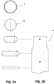
- the raw material rod 7 freed from its edge layer is shown in Figure 3a identified by the reference number 8.
- Removing the edge layer removes surface defects, for example an edge decarburization layer, scale, surface inaccuracies and the like.
- the cylindrical outer surface of the raw material rod 8 then has a significantly improved surface for the subsequent rolling process. In any case, previously existing surface imperfections are not rolled into the leaf spring or remain part of it.
- the raw material rod 8 is heated to its hardening temperature.
- the raw material rod 8 is heated to its austentization temperature.
- the raw material rod 8, which is at its hardening temperature is rolled with one or more passes, specifically to form its clamping section 2 and to form its spring arm 5
- Figure 3a the cross-sectional geometries of the parabolic spring 1 from the area of the clamping section 2, the spring arm 5 and the rolling end, also part of the spring arm 5, are shown.
- the location of the cross sections with respect to the parabolic spring 1 are with reference to FIG Figure 3b identified.
- the parabolic spring 1 in the representation of the Figure 3 is shown shortened in length.
- the end of the roll is rolled with a constant thickness.
- the eye 6 is formed from this in a subsequent step. In order to avoid the roll being cooled too far, it can be reheated one or more times, in those sections in which it has not yet been rolled out.
- the rolling process is thus carried out in the same heat and then tempered after shaping the parabolic spring 1. This freezes the rolling structure formed during rolling and prevents recrystallization.
- the spring arm is rolled out by applying a tensile load, so that the rolling out is accompanied by an elongation of the raw material rod 8. If certain narrow side or edge configurations are desired, it can be advisable to adjust this via vertical rolling of the narrow sides.
- the top view of the parabolic spring 1 in the Figure 3b illustrates the special waist of the clamping section 2 with respect to the spring arm 5. It has already been pointed out that this is a reason for saving weight. Because of the waist in the area of the clamping section 2 with respect to the spring arm 5, only a narrower design of clamp and saddle plates is required to connect the parabolic spring 1 to a vehicle axle. This also leads to weight loss. Construction space is also saved. Thus, parabolic springs of this type, if arranged horizontally next to one another, can be positioned closer to one another. The waist offers enough space to place a saddle plate and bridle screws.
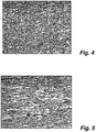
- the Figure 4 shows a schematic structural diagram of the raw material rod 8 with the cutting plane in the longitudinal extent of the same.
- the structure has no recognizable orientation.
- the grains have a largely symmetrical contour.
- Figure 5 shows in a comparison a schematic microstructure from the clamping section 2 of the parabolic spring 1, also with a sectional plane in the longitudinal extension of the parabolic spring 1. Due to the rolling out of the clamping section 2, as described above, this has become in Figure 5 Rolling structure shown formed. The structure is stretched. what by a Grain elongation is justified. This structure is responsible for the prescribed positive mechanical properties of the subsequent remuneration structure.
- a parabolic spring with molded eyes is shown as an example in the figures.
- the advantages of the invention also arise in the case of spring leaves which have no fastening means, such as eyes.
- any layer can be made using the concept of this invention.
Landscapes
- Engineering & Computer Science (AREA)
- Mechanical Engineering (AREA)
- General Engineering & Computer Science (AREA)
- Life Sciences & Earth Sciences (AREA)
- Agronomy & Crop Science (AREA)
- Springs (AREA)
- Vehicle Body Suspensions (AREA)
- Forging (AREA)
Priority Applications (1)
| Application Number | Priority Date | Filing Date | Title |
|---|---|---|---|
| PL18700720T PL3528978T3 (pl) | 2017-01-13 | 2018-01-09 | Sposób wytwarzania sprężyny piórowej oraz sprężyna piórowa |
Applications Claiming Priority (2)
| Application Number | Priority Date | Filing Date | Title |
|---|---|---|---|
| DE102017100575.7A DE102017100575B4 (de) | 2017-01-13 | 2017-01-13 | Verfahren zum Herstellen einer Blattfeder sowie Blattfeder |
| PCT/EP2018/050430 WO2018130509A1 (de) | 2017-01-13 | 2018-01-09 | Verfahren zum herstellen einer blattfeder sowie blattfeder |
Publications (2)
| Publication Number | Publication Date |
|---|---|
| EP3528978A1 EP3528978A1 (de) | 2019-08-28 |
| EP3528978B1 true EP3528978B1 (de) | 2020-05-27 |
Family
ID=61005799
Family Applications (1)
| Application Number | Title | Priority Date | Filing Date |
|---|---|---|---|
| EP18700720.8A Not-in-force EP3528978B1 (de) | 2017-01-13 | 2018-01-09 | Verfahren zum herstellen einer blattfeder sowie blattfeder |
Country Status (8)
| Country | Link |
|---|---|
| US (1) | US20190202254A1 (pl) |
| EP (1) | EP3528978B1 (pl) |
| JP (1) | JP2020506059A (pl) |
| CN (1) | CN109843468A (pl) |
| DE (1) | DE102017100575B4 (pl) |
| MX (1) | MX2019004315A (pl) |
| PL (1) | PL3528978T3 (pl) |
| WO (1) | WO2018130509A1 (pl) |
Family Cites Families (19)
| Publication number | Priority date | Publication date | Assignee | Title |
|---|---|---|---|---|
| GB959801A (en) | 1960-04-20 | 1964-06-03 | Rockwell Standard Co | Spring leaf and method for making |
| US3238072A (en) * | 1963-06-12 | 1966-03-01 | Rockwell Standard Co | Method of making taper leaf springs |
| US3853310A (en) * | 1970-05-08 | 1974-12-10 | Spectra Mcintosh Corp | Taper leaf spring blank |
| JPS5124055B2 (pl) * | 1971-12-20 | 1976-07-21 | ||
| JPS62227541A (ja) * | 1986-03-27 | 1987-10-06 | Kobe Steel Ltd | 異幅帯板の製造方法 |
| JP2509933B2 (ja) * | 1987-04-06 | 1996-06-26 | 日本発条株式会社 | Frp板ばね装置 |
| JP2512984B2 (ja) * | 1988-03-29 | 1996-07-03 | 住友金属工業株式会社 | スプリング用継目無鋼管の製造方法 |
| CN1013252B (zh) * | 1988-05-27 | 1991-07-24 | 鞍山钢铁公司 | 铸铁轧辊的焊补方法 |
| JPH071045B2 (ja) * | 1990-06-05 | 1995-01-11 | 日本発条株式会社 | 重ね板ばね |
| CN1144147A (zh) * | 1995-08-25 | 1997-03-05 | 宋玉泉 | 变截面弹簧的轧制工艺及设备 |
| JP2001328059A (ja) * | 2000-05-24 | 2001-11-27 | Aichi Steel Works Ltd | 金属製丸棒材の製造方法 |
| CN2518613Y (zh) * | 2001-07-18 | 2002-10-30 | 史习 | 一种可调整辊缝变化速度的液压仿形轧制装置 |
| JP2003305630A (ja) * | 2002-04-16 | 2003-10-28 | Daido Steel Co Ltd | 棒線材研磨装置 |
| JP2004308827A (ja) * | 2003-04-09 | 2004-11-04 | Sii Micro Parts Ltd | ぜんまいの製造方法 |
| DE10356312A1 (de) | 2003-11-28 | 2005-07-07 | Bam Anlagen Und Maschinen Gmbh + Co. Kg | Vorrichtung und Verfahren zum Warmauswalzen von Blattfedern |
| CN101561023B (zh) * | 2009-05-26 | 2010-09-15 | 青岛帅潮实业有限公司 | 无切削变截面钢板弹簧及其端部成形挤压装置 |
| DE102009036512B3 (de) | 2009-08-07 | 2011-06-16 | Schomäcker Federnwerk GmbH | Verfahren und Vorrichtung zum Herstellen von Parabellenkern und Parabelfedern für insbesondere Fahrzeugchassis, Fahrzeugaufbauten und dgl. |
| US20140191486A1 (en) * | 2013-01-10 | 2014-07-10 | Hendrickson Usa, L.L.C. | Multi-tapered suspension component |
| CN205859019U (zh) * | 2016-07-15 | 2017-01-04 | 安庆安簧汽车零部件有限公司 | 一片式钢板弹簧 |
-
2017
- 2017-01-13 DE DE102017100575.7A patent/DE102017100575B4/de not_active Expired - Fee Related
-
2018
- 2018-01-09 US US16/325,356 patent/US20190202254A1/en not_active Abandoned
- 2018-01-09 EP EP18700720.8A patent/EP3528978B1/de not_active Not-in-force
- 2018-01-09 MX MX2019004315A patent/MX2019004315A/es unknown
- 2018-01-09 PL PL18700720T patent/PL3528978T3/pl unknown
- 2018-01-09 CN CN201880003869.8A patent/CN109843468A/zh active Pending
- 2018-01-09 JP JP2019537167A patent/JP2020506059A/ja active Pending
- 2018-01-09 WO PCT/EP2018/050430 patent/WO2018130509A1/de not_active Ceased
Non-Patent Citations (1)
| Title |
|---|
| None * |
Also Published As
| Publication number | Publication date |
|---|---|
| WO2018130509A1 (de) | 2018-07-19 |
| DE102017100575A1 (de) | 2018-07-19 |
| MX2019004315A (es) | 2019-07-04 |
| EP3528978A1 (de) | 2019-08-28 |
| CN109843468A (zh) | 2019-06-04 |
| DE102017100575B4 (de) | 2019-04-25 |
| US20190202254A1 (en) | 2019-07-04 |
| JP2020506059A (ja) | 2020-02-27 |
| PL3528978T3 (pl) | 2020-10-05 |
Similar Documents
| Publication | Publication Date | Title |
|---|---|---|
| EP1121208B1 (de) | Verfahren und vorrichtung zum herstellen eines metallbandes für abzulängende tailored blanks | |
| EP3189165B1 (de) | Verfahren zum herstellen von kaltgeformten stahlfedern | |
| DE1281468B (de) | Verfahren zur Herstellung einer sich verjuengenden oder konisch verlaufenden Blattfeder | |
| DE60222785T2 (de) | Verfahren und gerät zur herstellung von schienen | |
| DE69329457T2 (de) | Hochstarke stahldrehstabilisatorteile und verfahren zur herstellung | |
| DE69328835T2 (de) | Kaltgeformte hochfeste stahlteile | |
| DE102016204567A1 (de) | Verfahren zum Herstellen eines warmwalzplattierten Werkstoffverbundes, Flachproduktpaket, warmwalzplattierter Werkstoffverbund sowie seine Verwendung | |
| DE102014214592B4 (de) | Schraubenfeder aus Federstahl und Verfahren zur Herstellung einer Schraubenfeder | |
| DE19704300B4 (de) | Verfahren zur Herstellung von Platinen mit unterschiedlichen Dicken | |
| DE68925731T2 (de) | Verfahren zur Herstellung eines Blattfederblattes | |
| EP3601837B1 (de) | Federblatt und verfahren zur herstellung eines federblattes | |
| EP3719341B1 (de) | Profilstab und daraus hergestellte fahrzeugfeder | |
| EP3528978B1 (de) | Verfahren zum herstellen einer blattfeder sowie blattfeder | |
| DE1427382A1 (de) | Federblatt und Verfahren zu seiner Herstellung | |
| DE850620C (de) | Verfahren zur Herstellung einer Einblattfeder von hoher Tragfestigkeit und Lebensdauer | |
| EP0645462A1 (de) | Verfahren zur Optimierung der Eigenspannungsverteilung in Federelementen | |
| DE1602548A1 (de) | Verfahren zur Herstellung eines geformten Federkerns | |
| DE4112812C2 (de) | Drehstab | |
| EP1802894B1 (de) | Hochfeste stahlkette für den tieftemperaturbereich | |
| AT520059B1 (de) | Federblatt für eine Blattfeder | |
| DE968459C (de) | Verfahren zur Herstellung hochfester Bolzenwerkstuecke mit Kopf, wie Schrauben und Nieten, durch Kaltumformung | |
| DE102014112762B4 (de) | Verfahren zum Herstellen von warmgeformten Stahlfedern | |
| DE102024112666B4 (de) | Verfahren zur Herstellung einer Fahrwerkskomponente, Fahrwerkskomponente und Verwendung eines Halbzeugs zur Herstellung einer Fahrwerkskomponente | |
| DE102014203767A1 (de) | Verfahren zur Herstellung von Fahrzeugbauteilen | |
| DE885809C (de) | Verfahren zum Herstellen geschlossener Kettenglieder |
Legal Events
| Date | Code | Title | Description |
|---|---|---|---|
| STAA | Information on the status of an ep patent application or granted ep patent |
Free format text: STATUS: UNKNOWN |
|
| STAA | Information on the status of an ep patent application or granted ep patent |
Free format text: STATUS: THE INTERNATIONAL PUBLICATION HAS BEEN MADE |
|
| PUAI | Public reference made under article 153(3) epc to a published international application that has entered the european phase |
Free format text: ORIGINAL CODE: 0009012 |
|
| STAA | Information on the status of an ep patent application or granted ep patent |
Free format text: STATUS: REQUEST FOR EXAMINATION WAS MADE |
|
| 17P | Request for examination filed |
Effective date: 20190215 |
|
| AK | Designated contracting states |
Kind code of ref document: A1 Designated state(s): AL AT BE BG CH CY CZ DE DK EE ES FI FR GB GR HR HU IE IS IT LI LT LU LV MC MK MT NL NO PL PT RO RS SE SI SK SM TR |
|
| AX | Request for extension of the european patent |
Extension state: BA ME |
|
| GRAP | Despatch of communication of intention to grant a patent |
Free format text: ORIGINAL CODE: EPIDOSNIGR1 |
|
| STAA | Information on the status of an ep patent application or granted ep patent |
Free format text: STATUS: GRANT OF PATENT IS INTENDED |
|
| DAV | Request for validation of the european patent (deleted) | ||
| DAX | Request for extension of the european patent (deleted) | ||
| INTG | Intention to grant announced |
Effective date: 20200117 |
|
| GRAS | Grant fee paid |
Free format text: ORIGINAL CODE: EPIDOSNIGR3 |
|
| GRAA | (expected) grant |
Free format text: ORIGINAL CODE: 0009210 |
|
| STAA | Information on the status of an ep patent application or granted ep patent |
Free format text: STATUS: THE PATENT HAS BEEN GRANTED |
|
| AK | Designated contracting states |
Kind code of ref document: B1 Designated state(s): AL AT BE BG CH CY CZ DE DK EE ES FI FR GB GR HR HU IE IS IT LI LT LU LV MC MK MT NL NO PL PT RO RS SE SI SK SM TR |
|
| REG | Reference to a national code |
Ref country code: GB Ref legal event code: FG4D Free format text: NOT ENGLISH |
|
| REG | Reference to a national code |
Ref country code: CH Ref legal event code: EP |
|
| REG | Reference to a national code |
Ref country code: AT Ref legal event code: REF Ref document number: 1274024 Country of ref document: AT Kind code of ref document: T Effective date: 20200615 |
|
| REG | Reference to a national code |
Ref country code: DE Ref legal event code: R096 Ref document number: 502018001537 Country of ref document: DE |
|
| REG | Reference to a national code |
Ref country code: NL Ref legal event code: FP |
|
| REG | Reference to a national code |
Ref country code: SE Ref legal event code: TRGR |
|
| REG | Reference to a national code |
Ref country code: LT Ref legal event code: MG4D |
|
| PG25 | Lapsed in a contracting state [announced via postgrant information from national office to epo] |
Ref country code: NO Free format text: LAPSE BECAUSE OF FAILURE TO SUBMIT A TRANSLATION OF THE DESCRIPTION OR TO PAY THE FEE WITHIN THE PRESCRIBED TIME-LIMIT Effective date: 20200827 Ref country code: IS Free format text: LAPSE BECAUSE OF FAILURE TO SUBMIT A TRANSLATION OF THE DESCRIPTION OR TO PAY THE FEE WITHIN THE PRESCRIBED TIME-LIMIT Effective date: 20200927 Ref country code: PT Free format text: LAPSE BECAUSE OF FAILURE TO SUBMIT A TRANSLATION OF THE DESCRIPTION OR TO PAY THE FEE WITHIN THE PRESCRIBED TIME-LIMIT Effective date: 20200928 Ref country code: LT Free format text: LAPSE BECAUSE OF FAILURE TO SUBMIT A TRANSLATION OF THE DESCRIPTION OR TO PAY THE FEE WITHIN THE PRESCRIBED TIME-LIMIT Effective date: 20200527 Ref country code: FI Free format text: LAPSE BECAUSE OF FAILURE TO SUBMIT A TRANSLATION OF THE DESCRIPTION OR TO PAY THE FEE WITHIN THE PRESCRIBED TIME-LIMIT Effective date: 20200527 Ref country code: GR Free format text: LAPSE BECAUSE OF FAILURE TO SUBMIT A TRANSLATION OF THE DESCRIPTION OR TO PAY THE FEE WITHIN THE PRESCRIBED TIME-LIMIT Effective date: 20200828 |
|
| PG25 | Lapsed in a contracting state [announced via postgrant information from national office to epo] |
Ref country code: LV Free format text: LAPSE BECAUSE OF FAILURE TO SUBMIT A TRANSLATION OF THE DESCRIPTION OR TO PAY THE FEE WITHIN THE PRESCRIBED TIME-LIMIT Effective date: 20200527 Ref country code: BG Free format text: LAPSE BECAUSE OF FAILURE TO SUBMIT A TRANSLATION OF THE DESCRIPTION OR TO PAY THE FEE WITHIN THE PRESCRIBED TIME-LIMIT Effective date: 20200827 Ref country code: RS Free format text: LAPSE BECAUSE OF FAILURE TO SUBMIT A TRANSLATION OF THE DESCRIPTION OR TO PAY THE FEE WITHIN THE PRESCRIBED TIME-LIMIT Effective date: 20200527 Ref country code: HR Free format text: LAPSE BECAUSE OF FAILURE TO SUBMIT A TRANSLATION OF THE DESCRIPTION OR TO PAY THE FEE WITHIN THE PRESCRIBED TIME-LIMIT Effective date: 20200527 |
|
| PG25 | Lapsed in a contracting state [announced via postgrant information from national office to epo] |
Ref country code: AL Free format text: LAPSE BECAUSE OF FAILURE TO SUBMIT A TRANSLATION OF THE DESCRIPTION OR TO PAY THE FEE WITHIN THE PRESCRIBED TIME-LIMIT Effective date: 20200527 |
|
| PG25 | Lapsed in a contracting state [announced via postgrant information from national office to epo] |
Ref country code: DK Free format text: LAPSE BECAUSE OF FAILURE TO SUBMIT A TRANSLATION OF THE DESCRIPTION OR TO PAY THE FEE WITHIN THE PRESCRIBED TIME-LIMIT Effective date: 20200527 Ref country code: SM Free format text: LAPSE BECAUSE OF FAILURE TO SUBMIT A TRANSLATION OF THE DESCRIPTION OR TO PAY THE FEE WITHIN THE PRESCRIBED TIME-LIMIT Effective date: 20200527 Ref country code: EE Free format text: LAPSE BECAUSE OF FAILURE TO SUBMIT A TRANSLATION OF THE DESCRIPTION OR TO PAY THE FEE WITHIN THE PRESCRIBED TIME-LIMIT Effective date: 20200527 Ref country code: RO Free format text: LAPSE BECAUSE OF FAILURE TO SUBMIT A TRANSLATION OF THE DESCRIPTION OR TO PAY THE FEE WITHIN THE PRESCRIBED TIME-LIMIT Effective date: 20200527 Ref country code: CZ Free format text: LAPSE BECAUSE OF FAILURE TO SUBMIT A TRANSLATION OF THE DESCRIPTION OR TO PAY THE FEE WITHIN THE PRESCRIBED TIME-LIMIT Effective date: 20200527 Ref country code: ES Free format text: LAPSE BECAUSE OF FAILURE TO SUBMIT A TRANSLATION OF THE DESCRIPTION OR TO PAY THE FEE WITHIN THE PRESCRIBED TIME-LIMIT Effective date: 20200527 |
|
| PG25 | Lapsed in a contracting state [announced via postgrant information from national office to epo] |
Ref country code: SK Free format text: LAPSE BECAUSE OF FAILURE TO SUBMIT A TRANSLATION OF THE DESCRIPTION OR TO PAY THE FEE WITHIN THE PRESCRIBED TIME-LIMIT Effective date: 20200527 |
|
| PGFP | Annual fee paid to national office [announced via postgrant information from national office to epo] |
Ref country code: PL Payment date: 20201109 Year of fee payment: 4 |
|
| REG | Reference to a national code |
Ref country code: DE Ref legal event code: R097 Ref document number: 502018001537 Country of ref document: DE |
|
| PLBE | No opposition filed within time limit |
Free format text: ORIGINAL CODE: 0009261 |
|
| STAA | Information on the status of an ep patent application or granted ep patent |
Free format text: STATUS: NO OPPOSITION FILED WITHIN TIME LIMIT |
|
| PGFP | Annual fee paid to national office [announced via postgrant information from national office to epo] |
Ref country code: FR Payment date: 20210120 Year of fee payment: 4 Ref country code: NL Payment date: 20210120 Year of fee payment: 4 Ref country code: IT Payment date: 20210131 Year of fee payment: 4 |
|
| 26N | No opposition filed |
Effective date: 20210302 |
|
| PGFP | Annual fee paid to national office [announced via postgrant information from national office to epo] |
Ref country code: TR Payment date: 20210105 Year of fee payment: 4 Ref country code: SE Payment date: 20210122 Year of fee payment: 4 Ref country code: DE Payment date: 20210114 Year of fee payment: 4 |
|
| PG25 | Lapsed in a contracting state [announced via postgrant information from national office to epo] |
Ref country code: MC Free format text: LAPSE BECAUSE OF FAILURE TO SUBMIT A TRANSLATION OF THE DESCRIPTION OR TO PAY THE FEE WITHIN THE PRESCRIBED TIME-LIMIT Effective date: 20200527 |
|
| REG | Reference to a national code |
Ref country code: CH Ref legal event code: PL |
|
| PG25 | Lapsed in a contracting state [announced via postgrant information from national office to epo] |
Ref country code: LU Free format text: LAPSE BECAUSE OF NON-PAYMENT OF DUE FEES Effective date: 20210109 |
|
| REG | Reference to a national code |
Ref country code: BE Ref legal event code: MM Effective date: 20210131 |
|
| PG25 | Lapsed in a contracting state [announced via postgrant information from national office to epo] |
Ref country code: LI Free format text: LAPSE BECAUSE OF NON-PAYMENT OF DUE FEES Effective date: 20210131 Ref country code: CH Free format text: LAPSE BECAUSE OF NON-PAYMENT OF DUE FEES Effective date: 20210131 |
|
| REG | Reference to a national code |
Ref country code: DE Ref legal event code: R082 Ref document number: 502018001537 Country of ref document: DE Representative=s name: HAVERKAMP PATENTANWAELTE PARTG MBB, DE |
|
| PG25 | Lapsed in a contracting state [announced via postgrant information from national office to epo] |
Ref country code: IE Free format text: LAPSE BECAUSE OF NON-PAYMENT OF DUE FEES Effective date: 20210109 |
|
| PG25 | Lapsed in a contracting state [announced via postgrant information from national office to epo] |
Ref country code: BE Free format text: LAPSE BECAUSE OF NON-PAYMENT OF DUE FEES Effective date: 20210131 |
|
| REG | Reference to a national code |
Ref country code: DE Ref legal event code: R119 Ref document number: 502018001537 Country of ref document: DE |
|
| REG | Reference to a national code |
Ref country code: SE Ref legal event code: EUG |
|
| REG | Reference to a national code |
Ref country code: NL Ref legal event code: MM Effective date: 20220201 |
|
| GBPC | Gb: european patent ceased through non-payment of renewal fee |
Effective date: 20220109 |
|
| PG25 | Lapsed in a contracting state [announced via postgrant information from national office to epo] |
Ref country code: SE Free format text: LAPSE BECAUSE OF NON-PAYMENT OF DUE FEES Effective date: 20220110 Ref country code: NL Free format text: LAPSE BECAUSE OF NON-PAYMENT OF DUE FEES Effective date: 20220201 Ref country code: GB Free format text: LAPSE BECAUSE OF NON-PAYMENT OF DUE FEES Effective date: 20220109 Ref country code: DE Free format text: LAPSE BECAUSE OF NON-PAYMENT OF DUE FEES Effective date: 20220802 |
|
| PG25 | Lapsed in a contracting state [announced via postgrant information from national office to epo] |
Ref country code: FR Free format text: LAPSE BECAUSE OF NON-PAYMENT OF DUE FEES Effective date: 20220131 |
|
| PG25 | Lapsed in a contracting state [announced via postgrant information from national office to epo] |
Ref country code: IT Free format text: LAPSE BECAUSE OF NON-PAYMENT OF DUE FEES Effective date: 20220109 |
|
| PG25 | Lapsed in a contracting state [announced via postgrant information from national office to epo] |
Ref country code: PL Free format text: LAPSE BECAUSE OF NON-PAYMENT OF DUE FEES Effective date: 20220109 |
|
| PG25 | Lapsed in a contracting state [announced via postgrant information from national office to epo] |
Ref country code: CY Free format text: LAPSE BECAUSE OF FAILURE TO SUBMIT A TRANSLATION OF THE DESCRIPTION OR TO PAY THE FEE WITHIN THE PRESCRIBED TIME-LIMIT Effective date: 20200527 |
|
| PG25 | Lapsed in a contracting state [announced via postgrant information from national office to epo] |
Ref country code: HU Free format text: LAPSE BECAUSE OF FAILURE TO SUBMIT A TRANSLATION OF THE DESCRIPTION OR TO PAY THE FEE WITHIN THE PRESCRIBED TIME-LIMIT; INVALID AB INITIO Effective date: 20180109 |
|
| PG25 | Lapsed in a contracting state [announced via postgrant information from national office to epo] |
Ref country code: SI Free format text: LAPSE BECAUSE OF FAILURE TO SUBMIT A TRANSLATION OF THE DESCRIPTION OR TO PAY THE FEE WITHIN THE PRESCRIBED TIME-LIMIT Effective date: 20200527 |
|
| REG | Reference to a national code |
Ref country code: AT Ref legal event code: MM01 Ref document number: 1274024 Country of ref document: AT Kind code of ref document: T Effective date: 20230109 |
|
| PG25 | Lapsed in a contracting state [announced via postgrant information from national office to epo] |
Ref country code: AT Free format text: LAPSE BECAUSE OF NON-PAYMENT OF DUE FEES Effective date: 20230109 |
|
| PG25 | Lapsed in a contracting state [announced via postgrant information from national office to epo] |
Ref country code: MK Free format text: LAPSE BECAUSE OF FAILURE TO SUBMIT A TRANSLATION OF THE DESCRIPTION OR TO PAY THE FEE WITHIN THE PRESCRIBED TIME-LIMIT Effective date: 20200527 Ref country code: AT Free format text: LAPSE BECAUSE OF NON-PAYMENT OF DUE FEES Effective date: 20230109 |
|
| PG25 | Lapsed in a contracting state [announced via postgrant information from national office to epo] |
Ref country code: TR Free format text: LAPSE BECAUSE OF NON-PAYMENT OF DUE FEES Effective date: 20220109 Ref country code: MT Free format text: LAPSE BECAUSE OF FAILURE TO SUBMIT A TRANSLATION OF THE DESCRIPTION OR TO PAY THE FEE WITHIN THE PRESCRIBED TIME-LIMIT Effective date: 20200527 |
|
| PGFP | Annual fee paid to national office [announced via postgrant information from national office to epo] |
Ref country code: AT Payment date: 20260410 Year of fee payment: 5 |