EP3528748B2 - Prothèse vasculaire intraluminale destinée à être implantée dans le c ur ou dans des vaisseaux cardiaques d'un patient - Google Patents
Prothèse vasculaire intraluminale destinée à être implantée dans le c ur ou dans des vaisseaux cardiaques d'un patient Download PDFInfo
- Publication number
- EP3528748B2 EP3528748B2 EP17788212.3A EP17788212A EP3528748B2 EP 3528748 B2 EP3528748 B2 EP 3528748B2 EP 17788212 A EP17788212 A EP 17788212A EP 3528748 B2 EP3528748 B2 EP 3528748B2
- Authority
- EP
- European Patent Office
- Prior art keywords
- vascular prosthesis
- prosthesis
- anchoring structure
- stent support
- shaped
- Prior art date
- Legal status (The legal status is an assumption and is not a legal conclusion. Google has not performed a legal analysis and makes no representation as to the accuracy of the status listed.)
- Active
Links
- 238000002513 implantation Methods 0.000 title claims description 4
- 230000000747 cardiac effect Effects 0.000 title description 4
- 230000002792 vascular Effects 0.000 claims description 111
- 238000004873 anchoring Methods 0.000 claims description 58
- 210000003709 heart valve Anatomy 0.000 claims description 30
- 239000000463 material Substances 0.000 claims description 15
- 230000017531 blood circulation Effects 0.000 claims description 5
- 238000011144 upstream manufacturing Methods 0.000 claims description 2
- 230000002526 effect on cardiovascular system Effects 0.000 claims 1
- 238000002224 dissection Methods 0.000 description 13
- 208000002251 Dissecting Aneurysm Diseases 0.000 description 9
- 210000000709 aorta Anatomy 0.000 description 9
- 210000001765 aortic valve Anatomy 0.000 description 6
- 206010002329 Aneurysm Diseases 0.000 description 5
- 206010002895 aortic dissection Diseases 0.000 description 4
- 230000001154 acute effect Effects 0.000 description 3
- 238000003780 insertion Methods 0.000 description 3
- 230000037431 insertion Effects 0.000 description 3
- 238000013508 migration Methods 0.000 description 3
- 230000005012 migration Effects 0.000 description 3
- 206010060874 Aortic rupture Diseases 0.000 description 2
- 206010010356 Congenital anomaly Diseases 0.000 description 2
- 239000004699 Ultra-high molecular weight polyethylene Substances 0.000 description 2
- 239000008280 blood Substances 0.000 description 2
- 210000004369 blood Anatomy 0.000 description 2
- 230000006835 compression Effects 0.000 description 2
- 238000007906 compression Methods 0.000 description 2
- 238000003745 diagnosis Methods 0.000 description 2
- 208000037265 diseases, disorders, signs and symptoms Diseases 0.000 description 2
- 239000007943 implant Substances 0.000 description 2
- 239000002184 metal Substances 0.000 description 2
- 210000003270 subclavian artery Anatomy 0.000 description 2
- 229920000785 ultra high molecular weight polyethylene Polymers 0.000 description 2
- 206010003210 Arteriosclerosis Diseases 0.000 description 1
- 208000009087 False Aneurysm Diseases 0.000 description 1
- 241001465754 Metazoa Species 0.000 description 1
- 239000004793 Polystyrene Substances 0.000 description 1
- 206010048975 Vascular pseudoaneurysm Diseases 0.000 description 1
- 210000000702 aorta abdominal Anatomy 0.000 description 1
- 210000002376 aorta thoracic Anatomy 0.000 description 1
- 208000011775 arteriosclerosis disease Diseases 0.000 description 1
- 230000001174 ascending effect Effects 0.000 description 1
- 238000005452 bending Methods 0.000 description 1
- 230000000740 bleeding effect Effects 0.000 description 1
- 210000004204 blood vessel Anatomy 0.000 description 1
- 238000005352 clarification Methods 0.000 description 1
- 208000018631 connective tissue disease Diseases 0.000 description 1
- 238000010276 construction Methods 0.000 description 1
- 210000004351 coronary vessel Anatomy 0.000 description 1
- 201000010099 disease Diseases 0.000 description 1
- 208000035475 disorder Diseases 0.000 description 1
- 230000006870 function Effects 0.000 description 1
- 230000001771 impaired effect Effects 0.000 description 1
- 238000003698 laser cutting Methods 0.000 description 1
- 239000000203 mixture Substances 0.000 description 1
- HLXZNVUGXRDIFK-UHFFFAOYSA-N nickel titanium Chemical compound [Ti].[Ti].[Ti].[Ti].[Ti].[Ti].[Ti].[Ti].[Ti].[Ti].[Ti].[Ni].[Ni].[Ni].[Ni].[Ni].[Ni].[Ni].[Ni].[Ni].[Ni].[Ni].[Ni].[Ni].[Ni] HLXZNVUGXRDIFK-UHFFFAOYSA-N 0.000 description 1
- 229910001000 nickel titanium Inorganic materials 0.000 description 1
- 210000000056 organ Anatomy 0.000 description 1
- 229920000728 polyester Polymers 0.000 description 1
- 229920002223 polystyrene Polymers 0.000 description 1
- -1 polytetrafluoroethylene Polymers 0.000 description 1
- 229920001343 polytetrafluoroethylene Polymers 0.000 description 1
- 239000004810 polytetrafluoroethylene Substances 0.000 description 1
- 229920002635 polyurethane Polymers 0.000 description 1
- 239000004814 polyurethane Substances 0.000 description 1
- 239000012781 shape memory material Substances 0.000 description 1
- 238000001356 surgical procedure Methods 0.000 description 1
- 229920002994 synthetic fiber Polymers 0.000 description 1
- 239000012209 synthetic fiber Substances 0.000 description 1
Images

Classifications
-
- A—HUMAN NECESSITIES
- A61—MEDICAL OR VETERINARY SCIENCE; HYGIENE
- A61F—FILTERS IMPLANTABLE INTO BLOOD VESSELS; PROSTHESES; DEVICES PROVIDING PATENCY TO, OR PREVENTING COLLAPSING OF, TUBULAR STRUCTURES OF THE BODY, e.g. STENTS; ORTHOPAEDIC, NURSING OR CONTRACEPTIVE DEVICES; FOMENTATION; TREATMENT OR PROTECTION OF EYES OR EARS; BANDAGES, DRESSINGS OR ABSORBENT PADS; FIRST-AID KITS
- A61F2/00—Filters implantable into blood vessels; Prostheses, i.e. artificial substitutes or replacements for parts of the body; Appliances for connecting them with the body; Devices providing patency to, or preventing collapsing of, tubular structures of the body, e.g. stents
- A61F2/02—Prostheses implantable into the body
- A61F2/24—Heart valves ; Vascular valves, e.g. venous valves; Heart implants, e.g. passive devices for improving the function of the native valve or the heart muscle; Transmyocardial revascularisation [TMR] devices; Valves implantable in the body
- A61F2/2412—Heart valves ; Vascular valves, e.g. venous valves; Heart implants, e.g. passive devices for improving the function of the native valve or the heart muscle; Transmyocardial revascularisation [TMR] devices; Valves implantable in the body with soft flexible valve members, e.g. tissue valves shaped like natural valves
- A61F2/2418—Scaffolds therefor, e.g. support stents
-
- A—HUMAN NECESSITIES
- A61—MEDICAL OR VETERINARY SCIENCE; HYGIENE
- A61F—FILTERS IMPLANTABLE INTO BLOOD VESSELS; PROSTHESES; DEVICES PROVIDING PATENCY TO, OR PREVENTING COLLAPSING OF, TUBULAR STRUCTURES OF THE BODY, e.g. STENTS; ORTHOPAEDIC, NURSING OR CONTRACEPTIVE DEVICES; FOMENTATION; TREATMENT OR PROTECTION OF EYES OR EARS; BANDAGES, DRESSINGS OR ABSORBENT PADS; FIRST-AID KITS
- A61F2/00—Filters implantable into blood vessels; Prostheses, i.e. artificial substitutes or replacements for parts of the body; Appliances for connecting them with the body; Devices providing patency to, or preventing collapsing of, tubular structures of the body, e.g. stents
- A61F2/02—Prostheses implantable into the body
- A61F2/04—Hollow or tubular parts of organs, e.g. bladders, tracheae, bronchi or bile ducts
- A61F2/06—Blood vessels
- A61F2/07—Stent-grafts
-
- A—HUMAN NECESSITIES
- A61—MEDICAL OR VETERINARY SCIENCE; HYGIENE
- A61F—FILTERS IMPLANTABLE INTO BLOOD VESSELS; PROSTHESES; DEVICES PROVIDING PATENCY TO, OR PREVENTING COLLAPSING OF, TUBULAR STRUCTURES OF THE BODY, e.g. STENTS; ORTHOPAEDIC, NURSING OR CONTRACEPTIVE DEVICES; FOMENTATION; TREATMENT OR PROTECTION OF EYES OR EARS; BANDAGES, DRESSINGS OR ABSORBENT PADS; FIRST-AID KITS
- A61F2/00—Filters implantable into blood vessels; Prostheses, i.e. artificial substitutes or replacements for parts of the body; Appliances for connecting them with the body; Devices providing patency to, or preventing collapsing of, tubular structures of the body, e.g. stents
- A61F2/82—Devices providing patency to, or preventing collapsing of, tubular structures of the body, e.g. stents
- A61F2/86—Stents in a form characterised by the wire-like elements; Stents in the form characterised by a net-like or mesh-like structure
- A61F2/90—Stents in a form characterised by the wire-like elements; Stents in the form characterised by a net-like or mesh-like structure characterised by a net-like or mesh-like structure
- A61F2/91—Stents in a form characterised by the wire-like elements; Stents in the form characterised by a net-like or mesh-like structure characterised by a net-like or mesh-like structure made from perforated sheet material or tubes, e.g. perforated by laser cuts or etched holes
-
- A—HUMAN NECESSITIES
- A61—MEDICAL OR VETERINARY SCIENCE; HYGIENE
- A61F—FILTERS IMPLANTABLE INTO BLOOD VESSELS; PROSTHESES; DEVICES PROVIDING PATENCY TO, OR PREVENTING COLLAPSING OF, TUBULAR STRUCTURES OF THE BODY, e.g. STENTS; ORTHOPAEDIC, NURSING OR CONTRACEPTIVE DEVICES; FOMENTATION; TREATMENT OR PROTECTION OF EYES OR EARS; BANDAGES, DRESSINGS OR ABSORBENT PADS; FIRST-AID KITS
- A61F2/00—Filters implantable into blood vessels; Prostheses, i.e. artificial substitutes or replacements for parts of the body; Appliances for connecting them with the body; Devices providing patency to, or preventing collapsing of, tubular structures of the body, e.g. stents
- A61F2/82—Devices providing patency to, or preventing collapsing of, tubular structures of the body, e.g. stents
- A61F2/86—Stents in a form characterised by the wire-like elements; Stents in the form characterised by a net-like or mesh-like structure
- A61F2/90—Stents in a form characterised by the wire-like elements; Stents in the form characterised by a net-like or mesh-like structure characterised by a net-like or mesh-like structure
-
- A—HUMAN NECESSITIES
- A61—MEDICAL OR VETERINARY SCIENCE; HYGIENE
- A61F—FILTERS IMPLANTABLE INTO BLOOD VESSELS; PROSTHESES; DEVICES PROVIDING PATENCY TO, OR PREVENTING COLLAPSING OF, TUBULAR STRUCTURES OF THE BODY, e.g. STENTS; ORTHOPAEDIC, NURSING OR CONTRACEPTIVE DEVICES; FOMENTATION; TREATMENT OR PROTECTION OF EYES OR EARS; BANDAGES, DRESSINGS OR ABSORBENT PADS; FIRST-AID KITS
- A61F2220/00—Fixations or connections for prostheses classified in groups A61F2/00 - A61F2/26 or A61F2/82 or A61F9/00 or A61F11/00 or subgroups thereof
- A61F2220/0008—Fixation appliances for connecting prostheses to the body
-
- A—HUMAN NECESSITIES
- A61—MEDICAL OR VETERINARY SCIENCE; HYGIENE
- A61F—FILTERS IMPLANTABLE INTO BLOOD VESSELS; PROSTHESES; DEVICES PROVIDING PATENCY TO, OR PREVENTING COLLAPSING OF, TUBULAR STRUCTURES OF THE BODY, e.g. STENTS; ORTHOPAEDIC, NURSING OR CONTRACEPTIVE DEVICES; FOMENTATION; TREATMENT OR PROTECTION OF EYES OR EARS; BANDAGES, DRESSINGS OR ABSORBENT PADS; FIRST-AID KITS
- A61F2230/00—Geometry of prostheses classified in groups A61F2/00 - A61F2/26 or A61F2/82 or A61F9/00 or A61F11/00 or subgroups thereof
- A61F2230/0002—Two-dimensional shapes, e.g. cross-sections
- A61F2230/0017—Angular shapes
- A61F2230/0026—Angular shapes trapezoidal
-
- A—HUMAN NECESSITIES
- A61—MEDICAL OR VETERINARY SCIENCE; HYGIENE
- A61F—FILTERS IMPLANTABLE INTO BLOOD VESSELS; PROSTHESES; DEVICES PROVIDING PATENCY TO, OR PREVENTING COLLAPSING OF, TUBULAR STRUCTURES OF THE BODY, e.g. STENTS; ORTHOPAEDIC, NURSING OR CONTRACEPTIVE DEVICES; FOMENTATION; TREATMENT OR PROTECTION OF EYES OR EARS; BANDAGES, DRESSINGS OR ABSORBENT PADS; FIRST-AID KITS
- A61F2250/00—Special features of prostheses classified in groups A61F2/00 - A61F2/26 or A61F2/82 or A61F9/00 or A61F11/00 or subgroups thereof
- A61F2250/0058—Additional features; Implant or prostheses properties not otherwise provided for
- A61F2250/0096—Markers and sensors for detecting a position or changes of a position of an implant, e.g. RF sensors, ultrasound markers
- A61F2250/0098—Markers and sensors for detecting a position or changes of a position of an implant, e.g. RF sensors, ultrasound markers radio-opaque, e.g. radio-opaque markers
Definitions
- the present invention relates to an intraluminal vascular prosthesis for implantation into the heart and/or cardiac vessels of a patient, in particular for anchoring in the area of the heart valve leaflets;
- the vascular prosthesis has a distal and a proximal end, as well as a stent framework and a prosthesis material with which the stent framework is at least partially covered, so that a covered proximal section and a non-covered distal section are formed.
- intraluminal vascular prostheses are used in the prior art in particular for the treatment of aneurysms or for replacing or supporting natural vessels or even heart valves.
- An aneurysm is an arterial dilatation or arterial bulging in which the cross-section of blood vessels locally expands in a spindle or sac shape as a result of congenital or acquired wall changes.
- Vascular prostheses used to treat aneurysms A distinction is made between a true aneurysm, a false aneurysm and a dissecting aneurysm ( aneurysma dissecans ), which occurs as a result of a vessel wall dissection. The latter refers to a splitting of the wall layers of the aorta, which is usually caused by a tear in the inner vessel wall, with subsequent bleeding between the layers.
- the risk factors that can lead to an aortic dissection include structural weakness of the vessel wall and arteriosclerosis.
- An aortic dissection is usually immediately life-threatening because it can lead to an aortic rupture and acute circulatory disorders in various organs. Immediate diagnosis is therefore crucial for this disease.
- aortic dissections most often (approx. 65%) occur just a few centimeters above the aortic valve, in the ascending section of the aorta ( ascending aorta ).
- the second most common (approx. 20%) aortic dissections occur immediately after the departure of the left subclavian artery ( arteria subclavia sinistra ) in the descending section of the aorta ( aorta descendens ).
- the aortic arch is affected with 10% and the abdominal aorta with 5%.
- aortic dissection is one of the most urgent emergencies in cardiology and heart surgery.
- the high mortality rate of one to two percent per hour in the acute phase of type A dissection requires immediate clarification of the suspected diagnosis.
- the artificial prostheses can be used either open surgically or minimally invasively.
- the WO 01/49213 discloses an intraluminal vascular prosthesis for implantation into a patient's heart.
- the stent framework of the intraluminal vascular prosthesis has a proximal and distal anchoring section, with the vascular prosthesis being covered as a whole.
- WO 2009/094188 A2 discloses a fully covered vascular prosthesis with anchoring structures at the proximal end.
- the object of the present invention is to provide a device with which the disadvantages described can be overcome and heart valve prostheses can be securely fixed in the heart, especially in type A dissections.
- vascular prosthesis of the type mentioned at the outset, with the vascular prosthesis at least at the proximal end one to three long wire-shaped anchoring structure(s), which is/are essentially loop-shaped, and which is/are each fixed with two ends to the stent framework and which each has its proximal end pointing in the proximal direction in the form of a loop and over the proximal end of the stent framework is/are positioned projecting out.
- the specific anchoring structure of the vascular prosthesis provided at the proximal end ensures that it is securely anchored in the heart without disrupting the natural function of the heart valves. This is achieved by the specific design of the anchoring structure, which extends in a loop-like or arch-like manner in the proximal direction at the proximal end.
- the vascular prosthesis can be positioned specifically and safely via this anchoring structure.
- the vascular prosthesis according to the invention serves as an anchor for a heart valve prosthesis to be inserted separately, which is released at least partially or overlappingly in the vascular prosthesis according to the invention anchored in the vessel, and which serves to support or replace the natural vascular prosthesis.
- Heart valve prosthesis can be used over the vascular prosthesis according to the invention, which heart valve prosthesis preferably has a self-expanding framework with valves attached therein.
- An example is given to the EP 2 724 690 referenced, in which examples of heart valves are disclosed. Based on this, it will be clear to the person skilled in the art which heart valves are suitable for use with the vascular prosthesis according to the invention.
- the anchoring structure ensures that additional suturing of the vascular prosthesis or the heart valve prosthesis to the vessels and thus strain on them can be avoided.
- the vascular prosthesis according to the invention thus represents a type of anchor structure or receiving structure, via which the heart valve prosthesis to be inserted in a second step can be securely anchored in the heart. This also avoids having to provide complicated fixation elements on the heart valve prosthesis itself in order to securely fix it in the heart.
- the anchoring structure is preferably positioned behind a leaflet of the aortic valve, preferably the noncoronary leaflet or "non coronary cusp "NCC", while the vascular prosthesis itself with the rest of its body is still fixed in the catheter via a retraction sheath or other compression. This can the anchoring structure can be precisely aligned and prevent subsequent proximal migration of the prosthesis.
- the vascular prosthesis according to the invention is preferably used to treat type A aortic dissections and is introduced in a minimally invasive manner via a catheter-guided application.
- distal and proximal are used in general and in this case to designate the respective ends of the vascular prosthesis, whereby the term “distal” refers to the part or end that is in relation to further downstream in the bloodstream.
- proximal refers, again in relation to the blood stream, to a part or end that is further upstream in relation to the blood stream.
- distal means in the direction of the blood flow
- proximal means opposite to the direction of the blood flow.
- distal refers to the end of the catheter or insertion system that is inserted into the patient or that is located furthest away from the user
- proximal means the end that is closer to the user
- the division of the base body of the vascular prosthesis into a proximal section and a distal section means that the respective sections differ from one another in their construction, and, for example, have a different number of stent rings or a different length of the stent framework, or whose stent rings/stent framework have different diameters and/or are covered (“covered”) or uncovered (“uncovered/not covered”) by prosthesis material.
- the prosthesis material can, for example, be sewn or shrunk or otherwise attached to the stent framework, either on the side of the stent framework facing the vessel wall, or on the inside, side facing the blood flow.
- the "covered" proximal section covered by prosthesis material is intended to bridge the dissection, the uncovered distal section is placed distal to the dissection and serves primarily - like the covered section - to fix the vascular prosthesis in the vessel.
- a "wire-shaped, substantially loop-shaped” anchoring structure herein means that the structure is formed by bending a wire or wire-like structure into an arch, having two “free” ends and an arch end opposite the two free ends. “Free ends” means that these are not connected to one another directly or in one piece, like the arch section.
- “Essentially” also means that the anchoring structure does not have to be bent exactly in a loop-shaped round, but should only be guided in the manner of a loop and is still viewed as such by a person skilled in the art.
- the anchoring structure projects beyond the proximal end of the vascular prosthesis in the proximal direction, with the anchoring structure being between approximately 1 cm and 3 cm, preferably approximately 1, 1.5, 2, 2.5 or 3 cm extends beyond the proximal end of the vascular prosthesis.
- the prosthetic material may include or be formed from a material selected from polyester, polyurethane, polystyrene, polytetrafluoroethylene, ultra-high molecular weight polyethylene (UHMPE), or mixtures thereof.
- a “stent framework” is understood to mean any wire prosthesis in the form of a tube or cylinder made of metal or synthetic fiber, which is preferably self-expanding and forms a lattice or net-like framework to which prosthetic material can be attached if necessary.
- This can be understood to mean, for example, a wire mesh, or so-called stent springs/stent rings arranged one behind the other in a meandering shape, which are possibly connected to one another via connecting supports made of wire, or which are only connected to one another via the implant material.
- the stent framework is usually made of a shape memory material, usually made of Nitinol, whereby the framework can return to the expanded state after being introduced into a vessel for release and can thereby "clamp" the vascular implant.
- the stent framework is a laser-cut stent framework or a braided or woven stent framework, or consists, if necessary only partially, (e.g. in the proximal section or in the distal section) of individual, only via the prosthesis material and not between the stent rings connected to each other (by bars or similar).
- the proximal section can have a different stent framework structure than the distal section of the vascular prosthesis, or both have the same stent framework.
- the stent framework has diamond-shaped cells or consists of circumferential rows of diamond-shaped cells arranged one behind the other, which adjoin one another or are connected to one another via their corners. At the extreme ends of the vascular prosthesis there are free “corners” of the diamond-shaped cells proximally and distally.
- fixing structures are provided at the distal end of the vascular prosthesis, via which the distal end of the vascular prosthesis can be fixed and kept compressed on a release catheter.
- the fixation structures are T-shaped extensions of at least three free corners of the diamond-shaped cells at the distal end. These T-shaped structures can engage corresponding T-shaped receptacles in the delivery catheter. A retraction sleeve, which is then passed over the distal end of the vascular prosthesis, holds the T-shaped fixation structures in the T-shaped receptacles and thus fixes the distal end of the vascular prosthesis to the release catheter.
- the T-shaped fixation structures can detach from the receptacles, thereby releasing the distal end of the vascular prosthesis.
- the distal ends of the wire-shaped anchoring structure are positioned at immediately adjacent corners of two diamond-shaped cells of the proximal end of the vascular prosthesis.
- the anchoring structure is stably "stretched" and an enlargement of the loop, which would possibly result in migration of the vascular prosthesis, is avoided. Due to the comparatively tight fixation of the distal ends of the loop, the anchoring structure is given rigidity via the proximal loop, which in turn ensures stable anchoring of the vascular prosthesis.
- the wire-shaped anchoring structure comprises a trapezoidal extension at/in its proximal end or end region.
- the trapezoidal extension gives the anchoring structure additional stability in this area, which further ensures secure anchoring in the vessel wall.
- the outermost proximal end of the wire-shaped anchoring structure is teardrop-shaped.
- “Teardrop-shaped” means a small attached loop pointing in the proximal direction in addition to the basic loop shape.
- the stent framework and the anchoring structure are formed in one piece.
- “In one piece” means that the stent framework and the anchoring structure were made from the same wire or the same laser-cut tube.
- one, two or three anchoring structures are provided at the proximal end of the stent framework.
- the vascular prosthesis can be fixed even more securely in the heart.
- the additional anchoring structures preferably have the same structure and shape, or different shapes; What they all have in common in these cases is the loop-shaped one Basic structure.
- the stent framework and/or the wire-shaped anchoring structure have hooks or thorns on their side facing away from and/or facing the vessel wall.
- the fixation of the vascular prosthesis in the vessel is further strengthened and secured.
- the hooks and/or thorns can be made of the same material as the anchoring structure or the stent framework, or of different materials.
- hooks/thorns provided on the inside of the vascular prosthesis, it is advantageous that these hooks or thorns further support the anchoring of a heart valve prosthesis to be at least partially inserted therein.
- the partial release and "clamping" of the heart valve prosthesis in the proximal end of the vascular prosthesis according to the invention ensures anchoring of the heart valve in the vascular prosthesis, the thorns and hooks can additionally support the anchoring of the heart valve in the vascular prosthesis.
- the stent framework and/or the wire-shaped anchoring structure comprises X-ray markers.
- X-ray markers on the anchoring structure makes it easier for the treating physician to correctly place the anchoring structure and thus also the vascular prosthesis as a whole, since he can thereby precisely place the vascular prosthesis in the heart under X-ray control.
- the intraluminal vascular prosthesis according to the invention preferably has a total diameter of between approximately 20 mm to approximately 48 mm, preferably between 24 mm to approximately 44 mm.
- the diameter of the vascular prosthesis is essentially constant over its entire length.
- the intraluminal vascular prosthesis further comprises a heart valve prosthesis, the heart valve prosthesis being designed in such a way that its distal end can be released at the proximal end of the intraluminal vascular prosthesis and can be fixed in the area of the heart valves via this.
- prostheses which together represent a system according to the invention for the treatment of an aortic dissection, in particular type A:
- an anchoring structure is provided, which is fixed in the heart in a first step and through which a heart valve prosthesis, which is inserted in a second step, can be securely anchored in the heart.
- the risk of the heart valve prosthesis slipping or migrating is thereby avoided, and at the same time a relatively simple structure of the system is achieved.
- FIG. 1 to 4 10 denotes a vascular prosthesis according to the invention overall, with a distal end 11 and a proximal end 12.
- the vascular prosthesis has a tubular stent framework 14, to which a prosthesis material 16 is attached in a proximal section 15, whereby the proximal section 15 is covered.
- the vascular prosthesis 10 further comprises a distal section 17 which is free of prosthesis material.
- the stent framework 14 can be a laser-cut stent framework, or one braided or woven from several wires Stent framework, or consist of individual, meandering stent rings arranged one behind the other, which are only connected to one another via the prosthesis material.
- the vascular prosthesis 10 has diamond-shaped cells 18 which form the tubular or cylindrical stent framework 14 in rows.
- fixing structures 19 are provided at three free corners of the diamond-shaped cells 18 at the distal end 11, via which the distal end 11 of the vascular prosthesis 10 is received in a release catheter (not shown) in corresponding receptacles or recesses and via a retraction sleeve guided over it (not shown) can be fixed to the release catheter.
- the fixing structures 19 are in the in Fig. 1 T-shaped embodiment shown.
- a wire-shaped anchoring structure 20 is provided, which forms a loop 21 in the proximal direction 12 '.
- the anchoring structure 20 extends approximately 1/3 of the total length of the vascular prosthesis 10 beyond its proximal end 12.
- the anchoring structure 20 has a proximal end 22, in the area of which the loop 21 is formed.
- the anchoring structure 20 further comprises two distal ends 23 and 24, which are fixed to two free corners 18 ', 18 "of the diamond-shaped cells 18 at the proximal end 12 of the vascular prosthesis or are formed in one piece with them.
- Fig. 1 As can be seen, the distal ends 23, 24 of the anchoring structure 20 are attached to/are provided in one piece with immediately adjacent corners of the diamond-shaped cells 18 at the proximal end 12 of the vascular prosthesis 10.
- Free ends of the diamond-shaped cells mean, as for any other embodiment of the vascular prosthesis according to the invention, that these corners are not connected to another diamond-shaped cell, but rather protrude freely in the distal direction 11 'or proximal direction 12'.
- the anchoring structure 20 has a trapezoidal extension 25 to the outside in the area of the loop 21. This means that the distance between the distal ends 23, 24 of the anchoring structure 20 in the area of its fixation/attachment to the proximal end 12 of the vascular prosthesis 10 is smaller than the distance between the opposing wires of the loop 21 in the proximal area 22.
- the anchoring structure 20 points, as further shown in Fig. 1 is shown, in its loop 21 an outermost teardrop-shaped proximal end 26.
- the anchoring structure 20 and the stent framework 14 can be formed in one piece, for example by laser cutting a corresponding tube or cylinder.
- the anchoring structure 20 and/or the stent framework can have hooks or thorns (not shown) on the side facing away from the vessel wall, as well as one or more X-ray markers.
- the diameter d of the vascular prosthesis according to the invention is preferably between 20 mm and 48 mm, preferably between approximately 24 mm and approximately 44 mm.
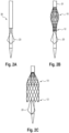
- a vascular prosthesis 10 loaded onto a release catheter 30 is shown schematically.
- the vascular prosthesis 10 is fixed at its distal end 11 via the fixing structures 19 provided there on the release catheter in appropriate receptacles and by covering a retraction cover 31.
- the vascular prosthesis 10 is also releasably fixed via its proximal end 12 to the release catheter 30 via a corresponding system (not shown).
- the completely fixed and compressed state of the vascular prosthesis 10 is in Fig. 2A shown.
- a central region of the vascular prosthesis 10 expands in a balloon shape, while the proximal and distal ends 12, 11 of the vascular prosthesis 10 are still fixed to the release catheter 30 (see Fig. 2B ).
- the vascular prosthesis 10 After the release of the proximal end 12 of the vascular prosthesis 10, it can expand, whereas the distal end 11 of the vascular prosthesis 10 is still fixed and compressed on the release catheter 30 and by the retraction sheath 31 (see Fig. 2C ). In this state, the vascular prosthesis 10 according to the invention can be released and positioned at the desired location, preferably behind a leaflet of the aortic valve (see also Fig. 3 ), preferably positioned behind the noncoronary cusp "NCC". This allows the anchoring structure 20 to be precisely aligned and prevent later proximal migration of the vascular prosthesis.
- the remaining vascular prosthesis can be released by completely retracting the retraction sheath 31.
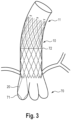
- the state of the vascular prosthesis 10 that is completely released in a heart 70 is in Fig. 3 shown, in which figure the vascular prosthesis is shown in dashed lines for better clarity. It can be seen here that anchoring structure 20 is positioned behind a leaflet of the aortic valve 71 while the rest of the vascular prosthesis 10 extends distally into the ascending aorta 72.
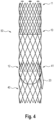
- Fig. 4 finally shows a system 50 according to the invention consisting of a vascular prosthesis 10 and a heart valve prosthesis 40 in assembled form, specifically outside the heart for better clarity.
- the heart valve prosthesis 40 can be inserted over it and released in such a way that The heart valve prosthesis 40 gets caught with its distal end 41 in the vascular prosthesis 10 at least partially at its proximal end 12 or is already fixed there by expansion.
Claims (10)
- Prothèse vasculaire intraluminale (10) destinée à être implantée dans le coeur (70) et/ou dans des vaisseaux coronaires d'un patient, en particulier pour l'ancrage dans la région des feuillets de valve cardiaque (71), comprenant une extrémité distale (11) et une extrémité proximale (12), l'extrémité distale (11) étant située plus en aval par rapport au flux sanguin et l'extrémité proximale (12) étant située plus en amont par rapport au flux sanguin, la prothèse vasculaire (10) présentant une armature d'endoprothèse (14) ainsi qu'un matériau de prothèse (16) avec lequel l'armature d'endoprothèse (14) est au moins en partie recouverte, de telle sorte qu'une portion proximale couverte (15) et une portion distale non couverte (17) soient formées, caractérisée en ce que la prothèse vasculaire (10) présente, à l'extrémité proximale (12), au moins une à trois structures d'ancrage allongées en forme de fil (20) qui sont essentiellement en forme de boucles et qui sont fixées à chaque fois par deux extrémités (23 ; 24) à l'armature d'endoprothèse (14), et qui sont positionnées à chaque fois avec leur extrémité proximale (22) en forme de boucle (21) orientée dans la direction proximale (12') et en saillie au-delà de l'extrémité proximale (12) de l'armature d'endoprothèse (14), et la structure d'ancrage en forme de fil (20) comprend, dans la région de la boucle (21), un élargissement trapézoïdal (25).
- Prothèse vasculaire intraluminale (10) selon la revendication 1, caractérisée en ce que les extrémités distales (23 ; 24) de la structure d'ancrage en forme de fil (20) sont positionnées au niveau de coins directement adjacents (18' ; 18") de deux cellules en forme de losange (18).
- Prothèse vasculaire intraluminale (10) selon l'une quelconque des revendications précédentes, caractérisée en ce que l'extrémité proximale la plus extérieure (26) de la structure d'ancrage en forme de fil est en forme de goutte.
- Prothèse vasculaire intraluminale (10) selon l'une quelconque des revendications précédentes, caractérisée en ce que l'armature d'endoprothèse (14) est une armature d'endoprothèse découpée au laser ou une armature d'endoprothèse tressée ou tissée.
- Prothèse vasculaire intraluminale (10) selon l'une quelconque des revendications précédentes, caractérisée en ce que l'armature d'endoprothèse (14) et la structure d'ancrage (20) sont réalisées d'une seule pièce.
- Prothèse vasculaire intraluminale (10) selon l'une quelconque des revendications précédentes, caractérisée en ce que l'armature d'endoprothèse (14) et/ou la structure d'ancrage en forme de fil (20) présentent, au niveau de leur côté opposé à la paroi du vaisseau, des crochets ou des épines.
- Prothèse vasculaire intraluminale (10) selon l'une quelconque des revendications précédentes, caractérisée en ce que l'armature d'endoprothèse (14) présente, au niveau de son côté tourné vers la paroi du vaisseau, des crochets ou des épines.
- Prothèse vasculaire intraluminale (10) selon l'une quelconque des revendications précédentes, caractérisée en ce que l'armature d'endoprothèse (14) et/ou la structure d'ancrage en forme de fil comprennent des marqueurs radiographiques.
- Prothèse vasculaire intraluminale (10) selon l'une quelconque des revendications précédentes, caractérisée en ce qu'elle présente un diamètre compris entre environ 20 mm et environ 48 mm, de préférence compris entre 24 mm et environ 44 mm.
- Prothèse vasculaire intraluminale (10) selon l'une quelconque des revendications 1 à 9, comprenant en outre une prothèse de valve cardiaque (40), la prothèse de valve cardiaque (40) étant réalisée de telle sorte qu'elle puisse être libérée avec son extrémité distale (41) à l'extrémité proximale (12) de la prothèse vasculaire intraluminale (10) et qu'elle puisse être fixée par le biais de celle-ci dans la région des valves cardiaques.
Applications Claiming Priority (2)
| Application Number | Priority Date | Filing Date | Title |
|---|---|---|---|
| DE202016105963.1U DE202016105963U1 (de) | 2016-10-24 | 2016-10-24 | Intraluminale Gefäßprothese zur Implantation in das Herz oder Herzgefäße eines Patienten |
| PCT/EP2017/077044 WO2018077821A1 (fr) | 2016-10-24 | 2017-10-24 | Prothèse vasculaire intraluminale destinée à être implantée dans le cœur ou dans des vaisseaux cardiaques d'un patient |
Publications (3)
| Publication Number | Publication Date |
|---|---|
| EP3528748A1 EP3528748A1 (fr) | 2019-08-28 |
| EP3528748B1 EP3528748B1 (fr) | 2021-01-20 |
| EP3528748B2 true EP3528748B2 (fr) | 2024-02-14 |
Family
ID=60164699
Family Applications (1)
| Application Number | Title | Priority Date | Filing Date |
|---|---|---|---|
| EP17788212.3A Active EP3528748B2 (fr) | 2016-10-24 | 2017-10-24 | Prothèse vasculaire intraluminale destinée à être implantée dans le c ur ou dans des vaisseaux cardiaques d'un patient |
Country Status (7)
| Country | Link |
|---|---|
| US (1) | US11007055B2 (fr) |
| EP (1) | EP3528748B2 (fr) |
| JP (1) | JP6831009B2 (fr) |
| CN (1) | CN109862852B (fr) |
| DE (1) | DE202016105963U1 (fr) |
| ES (1) | ES2866932T3 (fr) |
| WO (1) | WO2018077821A1 (fr) |
Families Citing this family (18)
| Publication number | Priority date | Publication date | Assignee | Title |
|---|---|---|---|---|
| US8579964B2 (en) | 2010-05-05 | 2013-11-12 | Neovasc Inc. | Transcatheter mitral valve prosthesis |
| US9554897B2 (en) | 2011-04-28 | 2017-01-31 | Neovasc Tiara Inc. | Methods and apparatus for engaging a valve prosthesis with tissue |
| US9308087B2 (en) | 2011-04-28 | 2016-04-12 | Neovasc Tiara Inc. | Sequentially deployed transcatheter mitral valve prosthesis |
| US9345573B2 (en) | 2012-05-30 | 2016-05-24 | Neovasc Tiara Inc. | Methods and apparatus for loading a prosthesis onto a delivery system |
| US9572665B2 (en) | 2013-04-04 | 2017-02-21 | Neovasc Tiara Inc. | Methods and apparatus for delivering a prosthetic valve to a beating heart |
| BR102015011376B1 (pt) | 2015-05-18 | 2023-04-04 | Murilo Pundek Rocha | Brônquio artificial implantável |
| CA3007670A1 (fr) | 2016-01-29 | 2017-08-03 | Neovasc Tiara Inc. | Valvule prothetique permettant d'eviter une obstruction empechant l'ecoulement |
| WO2018090148A1 (fr) | 2016-11-21 | 2018-05-24 | Neovasc Tiara Inc. | Procédés et systèmes de rétraction rapide d'un système de pose de valvule cardiaque transcathéter |
| CA3073834A1 (fr) | 2017-08-25 | 2019-02-28 | Neovasc Tiara Inc. | Prothese de valvule mitrale transcatheter a deploiement sequentiel |
| EP3876870B1 (fr) | 2018-11-08 | 2023-12-20 | Neovasc Tiara Inc. | Déploiement ventriculaire d'une prothèse de valvule mitrale transcathéter |
| WO2020191203A1 (fr) | 2019-03-20 | 2020-09-24 | inQB8 Medical Technologies, LLC | Implant de dissection aortique |
| CA3135753C (fr) | 2019-04-01 | 2023-10-24 | Neovasc Tiara Inc. | Valve prothetique deployable de maniere controlable |
| US11491006B2 (en) | 2019-04-10 | 2022-11-08 | Neovasc Tiara Inc. | Prosthetic valve with natural blood flow |
| AU2020279750B2 (en) | 2019-05-20 | 2023-07-13 | Neovasc Tiara Inc. | Introducer with hemostasis mechanism |
| EP3986332A4 (fr) | 2019-06-20 | 2023-07-19 | Neovasc Tiara Inc. | Valve mitrale prothétique à profil bas |
| USD902407S1 (en) * | 2019-11-19 | 2020-11-17 | Pulmair Medical, Inc. | Implantable artificial bronchus |
| USD954953S1 (en) | 2020-11-03 | 2022-06-14 | Pulmair Medical, Inc. | Implantable artificial bronchus |
| USD1014758S1 (en) | 2023-04-19 | 2024-02-13 | Pulmair Medical, Inc. | Implantable artificial bronchus |
Citations (18)
| Publication number | Priority date | Publication date | Assignee | Title |
|---|---|---|---|---|
| EP0657147A2 (fr) † | 1993-11-04 | 1995-06-14 | C.R. Bard, Inc. | Prothèse vasculaire non migrante et son système d'implantation peu agressif |
| US20030040792A1 (en) † | 2000-09-12 | 2003-02-27 | Shlomo Gabbay | Heart valve prosthesis and sutureless implantation of a heart valve prosthesis |
| US6579314B1 (en) † | 1995-03-10 | 2003-06-17 | C.R. Bard, Inc. | Covered stent with encapsulated ends |
| US20030236568A1 (en) † | 2002-05-10 | 2003-12-25 | Hikmat Hojeibane | Multi-lobed frame based unidirectional flow prosthetic implant |
| US20040082989A1 (en) † | 2002-08-20 | 2004-04-29 | Cook Incorporated | Stent graft with improved proximal end |
| US20040236411A1 (en) † | 2001-07-19 | 2004-11-25 | The Cleveland Clinic Foundation | Prosthetic cardiac valve and method for making same |
| US20050096734A1 (en) † | 2003-10-31 | 2005-05-05 | Majercak David C. | Implantable valvular prosthesis |
| US20050222674A1 (en) † | 2004-03-31 | 2005-10-06 | Med Institute, Inc. | Endoluminal graft with a prosthetic valve |
| US20080036113A1 (en) † | 2002-05-10 | 2008-02-14 | Iksoo Chun | Method of forming a tubular membrane on a structural frame |
| US20080177381A1 (en) † | 2007-01-19 | 2008-07-24 | The Cleveland Clinic Foundation | Method for implanting a cardiovascular valve |
| WO2010006627A1 (fr) † | 2008-07-17 | 2010-01-21 | Nvt Ag | Système de prothèse de valvule cardiaque |
| WO2011051043A1 (fr) † | 2009-11-02 | 2011-05-05 | Symetis Sa | Bioprothèse aortique et systèmes de mise en place de celle-ci |
| US20110125249A1 (en) † | 2009-11-19 | 2011-05-26 | Med Institute, Inc. | Stent Graft and Introducer Assembly |
| WO2012032187A1 (fr) † | 2010-09-10 | 2012-03-15 | Symetis Sa | Dispositifs de remplacement de valve, dispositif d'acheminement pour dispositif de remplacement de valve et procédé de fabrication d'un dispositif de remplacement de valve |
| US20130090714A1 (en) † | 2011-10-11 | 2013-04-11 | Cook Medical Technologies Llc | Stent delivery, repositioning, and removal system |
| US20140039614A1 (en) † | 2007-08-21 | 2014-02-06 | Symetis Sa | Stent-Valves For Valve Replacement and Associated Methods and Systems for Surgery |
| EP2926767A1 (fr) † | 2003-12-23 | 2015-10-07 | Boston Scientific Scimed, Inc. | Valve cardiaque repositionnable |
| US9693860B2 (en) † | 2014-12-01 | 2017-07-04 | Medtronic, Inc. | Segmented transcatheter valve prosthesis having an unsupported valve segment |
Family Cites Families (24)
| Publication number | Priority date | Publication date | Assignee | Title |
|---|---|---|---|---|
| US20070043435A1 (en) * | 1999-11-17 | 2007-02-22 | Jacques Seguin | Non-cylindrical prosthetic valve system for transluminal delivery |
| US6458153B1 (en) * | 1999-12-31 | 2002-10-01 | Abps Venture One, Ltd. | Endoluminal cardiac and venous valve prostheses and methods of manufacture and delivery thereof |
| US6503272B2 (en) * | 2001-03-21 | 2003-01-07 | Cordis Corporation | Stent-based venous valves |
| DE10301026B4 (de) * | 2002-08-13 | 2014-10-30 | Jenavalve Technology Inc. | Vorrichtung zur Verankerung und Ausrichtung von Herzklappenprothesen |
| US7347869B2 (en) * | 2003-10-31 | 2008-03-25 | Cordis Corporation | Implantable valvular prosthesis |
| JP5593545B2 (ja) * | 2006-12-06 | 2014-09-24 | メドトロニック シーブイ ルクセンブルク エス.アー.エール.エル. | 弁輪に固定された自己拡張型弁の経心尖的送達のためのシステムおよび方法 |
| WO2008097589A1 (fr) * | 2007-02-05 | 2008-08-14 | Boston Scientific Limited | Valve percutanée, système et procédé |
| US9138315B2 (en) * | 2007-04-13 | 2015-09-22 | Jenavalve Technology Gmbh | Medical device for treating a heart valve insufficiency or stenosis |
| EP2157937B1 (fr) * | 2007-06-04 | 2017-03-22 | Sequent Medical, Inc. | Dispositifs pour le traitement de défauts vasculaires |
| US7972378B2 (en) * | 2008-01-24 | 2011-07-05 | Medtronic, Inc. | Stents for prosthetic heart valves |
| ES2586532T3 (es) | 2011-06-01 | 2016-10-17 | Nvt Ag | Sistema de despliegue de prótesis de válvula cardiaca |
| WO2013134214A1 (fr) * | 2012-03-05 | 2013-09-12 | The Trustees Of The University Of Pennsylvania | Stents revêtus superabsorbants pour réduction vasculaire et ancrage de remplacement de valve |
| EP2858711B1 (fr) * | 2012-06-06 | 2018-03-07 | Magenta Medical Ltd. | Valve rénale prothétique |
| JP6563394B2 (ja) * | 2013-08-30 | 2019-08-21 | イェーナヴァルヴ テクノロジー インコーポレイテッド | 人工弁のための径方向に折り畳み自在のフレーム及び当該フレームを製造するための方法 |
| US10646333B2 (en) | 2013-10-24 | 2020-05-12 | Medtronic, Inc. | Two-piece valve prosthesis with anchor stent and valve component |
| US20150122687A1 (en) * | 2013-11-06 | 2015-05-07 | Edwards Lifesciences Corporation | Bioprosthetic heart valves having adaptive seals to minimize paravalvular leakage |
| ES2711663T3 (es) * | 2014-03-18 | 2019-05-06 | Nvt Ag | Implante de válvula cardiaca |
| PL3000437T3 (pl) * | 2014-09-26 | 2018-10-31 | Nvt Ag | Wszczepialne urządzenie do leczenia niedomykalności zastawki mitralnej |
| CN104274259B (zh) * | 2014-10-30 | 2016-06-01 | 宁波健世生物科技有限公司 | 一种带瓣叶夹持装置的人工瓣膜假体 |
| EP3028668A1 (fr) * | 2014-12-05 | 2016-06-08 | Nvt Ag | Système de valvule cardiaque prothétique et système d'administration à cet effet |
| US10285809B2 (en) | 2015-03-06 | 2019-05-14 | Boston Scientific Scimed Inc. | TAVI anchoring assist device |
| JP2018530386A (ja) * | 2015-10-13 | 2018-10-18 | ヴェナラム メディカル, エルエルシーVenarum Medical, Llc | 植え込み可能弁及び方法 |
| ES2875921T3 (es) * | 2015-12-22 | 2021-11-11 | Medira Ag | Dispositivo protésico de mejora de coaptación de válvula mitral |
| CN105496607A (zh) * | 2016-01-11 | 2016-04-20 | 北京迈迪顶峰医疗科技有限公司 | 一种经导管输送主动脉瓣瓣膜装置 |
-
2016
- 2016-10-24 DE DE202016105963.1U patent/DE202016105963U1/de active Active
-
2017
- 2017-10-24 JP JP2019521708A patent/JP6831009B2/ja active Active
- 2017-10-24 EP EP17788212.3A patent/EP3528748B2/fr active Active
- 2017-10-24 ES ES17788212T patent/ES2866932T3/es active Active
- 2017-10-24 WO PCT/EP2017/077044 patent/WO2018077821A1/fr active Application Filing
- 2017-10-24 CN CN201780066034.2A patent/CN109862852B/zh active Active
-
2019
- 2019-04-23 US US16/391,405 patent/US11007055B2/en active Active
Patent Citations (18)
| Publication number | Priority date | Publication date | Assignee | Title |
|---|---|---|---|---|
| EP0657147A2 (fr) † | 1993-11-04 | 1995-06-14 | C.R. Bard, Inc. | Prothèse vasculaire non migrante et son système d'implantation peu agressif |
| US6579314B1 (en) † | 1995-03-10 | 2003-06-17 | C.R. Bard, Inc. | Covered stent with encapsulated ends |
| US20030040792A1 (en) † | 2000-09-12 | 2003-02-27 | Shlomo Gabbay | Heart valve prosthesis and sutureless implantation of a heart valve prosthesis |
| US20040236411A1 (en) † | 2001-07-19 | 2004-11-25 | The Cleveland Clinic Foundation | Prosthetic cardiac valve and method for making same |
| US20080036113A1 (en) † | 2002-05-10 | 2008-02-14 | Iksoo Chun | Method of forming a tubular membrane on a structural frame |
| US20030236568A1 (en) † | 2002-05-10 | 2003-12-25 | Hikmat Hojeibane | Multi-lobed frame based unidirectional flow prosthetic implant |
| US20040082989A1 (en) † | 2002-08-20 | 2004-04-29 | Cook Incorporated | Stent graft with improved proximal end |
| US20050096734A1 (en) † | 2003-10-31 | 2005-05-05 | Majercak David C. | Implantable valvular prosthesis |
| EP2926767A1 (fr) † | 2003-12-23 | 2015-10-07 | Boston Scientific Scimed, Inc. | Valve cardiaque repositionnable |
| US20050222674A1 (en) † | 2004-03-31 | 2005-10-06 | Med Institute, Inc. | Endoluminal graft with a prosthetic valve |
| US20080177381A1 (en) † | 2007-01-19 | 2008-07-24 | The Cleveland Clinic Foundation | Method for implanting a cardiovascular valve |
| US20140039614A1 (en) † | 2007-08-21 | 2014-02-06 | Symetis Sa | Stent-Valves For Valve Replacement and Associated Methods and Systems for Surgery |
| WO2010006627A1 (fr) † | 2008-07-17 | 2010-01-21 | Nvt Ag | Système de prothèse de valvule cardiaque |
| WO2011051043A1 (fr) † | 2009-11-02 | 2011-05-05 | Symetis Sa | Bioprothèse aortique et systèmes de mise en place de celle-ci |
| US20110125249A1 (en) † | 2009-11-19 | 2011-05-26 | Med Institute, Inc. | Stent Graft and Introducer Assembly |
| WO2012032187A1 (fr) † | 2010-09-10 | 2012-03-15 | Symetis Sa | Dispositifs de remplacement de valve, dispositif d'acheminement pour dispositif de remplacement de valve et procédé de fabrication d'un dispositif de remplacement de valve |
| US20130090714A1 (en) † | 2011-10-11 | 2013-04-11 | Cook Medical Technologies Llc | Stent delivery, repositioning, and removal system |
| US9693860B2 (en) † | 2014-12-01 | 2017-07-04 | Medtronic, Inc. | Segmented transcatheter valve prosthesis having an unsupported valve segment |
Also Published As
| Publication number | Publication date |
|---|---|
| EP3528748A1 (fr) | 2019-08-28 |
| CN109862852B (zh) | 2021-04-09 |
| JP2019531828A (ja) | 2019-11-07 |
| US11007055B2 (en) | 2021-05-18 |
| CN109862852A (zh) | 2019-06-07 |
| JP6831009B2 (ja) | 2021-02-17 |
| DE202016105963U1 (de) | 2018-01-25 |
| EP3528748B1 (fr) | 2021-01-20 |
| ES2866932T3 (es) | 2021-10-20 |
| US20190254817A1 (en) | 2019-08-22 |
| WO2018077821A1 (fr) | 2018-05-03 |
Similar Documents
| Publication | Publication Date | Title |
|---|---|---|
| EP3528748B2 (fr) | Prothèse vasculaire intraluminale destinée à être implantée dans le c ur ou dans des vaisseaux cardiaques d'un patient | |
| DE60309843T2 (de) | Vorrichtung zur verankerung von endoluminalprothesen | |
| EP3897454B1 (fr) | Dispositif pour introduire et mettre en place un implant dans un vaisseau sanguin | |
| EP2809265B1 (fr) | Endoprothèse modulaire | |
| EP2809267B1 (fr) | Prothèse vasculaire endoluminale | |
| EP3203931B1 (fr) | Système de prothèse vasculaire | |
| EP3060177B1 (fr) | Implant vasculaire présentant des zones de force radiale différente | |
| EP3215055B1 (fr) | Système d'endoprothèse couverte modulaire | |
| WO2014026870A9 (fr) | Dispositif implantable destiné à être utilisé dans un corps humain et/ou animal pour remplacer un clapet organique | |
| DE102017120819A1 (de) | Intraluminales Gefäßprothesensystem | |
| WO2014072501A2 (fr) | Endoprothèses vasculaires sous forme de stent, stent, système de stents emboîtés et kit associé | |
| EP3630009A1 (fr) | Endoprothèse à poches | |
| EP2846732B1 (fr) | Prothèse vasculaire intraluminale à fenestration in situ | |
| EP2846731B1 (fr) | Prothèse vasculaire intraluminale à fenestration in situ | |
| DE102017115898A1 (de) | Intraluminale Gefäßprothese | |
| EP3694449A1 (fr) | Implant vasculaire expansible | |
| DE102019121930A1 (de) | Gefäßprothese |
Legal Events
| Date | Code | Title | Description |
|---|---|---|---|
| STAA | Information on the status of an ep patent application or granted ep patent |
Free format text: STATUS: UNKNOWN |
|
| STAA | Information on the status of an ep patent application or granted ep patent |
Free format text: STATUS: THE INTERNATIONAL PUBLICATION HAS BEEN MADE |
|
| PUAI | Public reference made under article 153(3) epc to a published international application that has entered the european phase |
Free format text: ORIGINAL CODE: 0009012 |
|
| STAA | Information on the status of an ep patent application or granted ep patent |
Free format text: STATUS: REQUEST FOR EXAMINATION WAS MADE |
|
| 17P | Request for examination filed |
Effective date: 20190328 |
|
| AK | Designated contracting states |
Kind code of ref document: A1 Designated state(s): AL AT BE BG CH CY CZ DE DK EE ES FI FR GB GR HR HU IE IS IT LI LT LU LV MC MK MT NL NO PL PT RO RS SE SI SK SM TR |
|
| AX | Request for extension of the european patent |
Extension state: BA ME |
|
| DAV | Request for validation of the european patent (deleted) | ||
| DAX | Request for extension of the european patent (deleted) | ||
| REG | Reference to a national code |
Ref country code: DE Ref legal event code: R079 Ref document number: 502017009160 Country of ref document: DE Free format text: PREVIOUS MAIN CLASS: A61F0002240000 Ipc: A61F0002070000 |
|
| GRAP | Despatch of communication of intention to grant a patent |
Free format text: ORIGINAL CODE: EPIDOSNIGR1 |
|
| STAA | Information on the status of an ep patent application or granted ep patent |
Free format text: STATUS: GRANT OF PATENT IS INTENDED |
|
| RIC1 | Information provided on ipc code assigned before grant |
Ipc: A61F 2/90 20130101ALN20200622BHEP Ipc: A61F 2/24 20060101ALI20200622BHEP Ipc: A61F 2/07 20130101AFI20200622BHEP |
|
| INTG | Intention to grant announced |
Effective date: 20200728 |
|
| GRAS | Grant fee paid |
Free format text: ORIGINAL CODE: EPIDOSNIGR3 |
|
| GRAA | (expected) grant |
Free format text: ORIGINAL CODE: 0009210 |
|
| STAA | Information on the status of an ep patent application or granted ep patent |
Free format text: STATUS: THE PATENT HAS BEEN GRANTED |
|
| AK | Designated contracting states |
Kind code of ref document: B1 Designated state(s): AL AT BE BG CH CY CZ DE DK EE ES FI FR GB GR HR HU IE IS IT LI LT LU LV MC MK MT NL NO PL PT RO RS SE SI SK SM TR |
|
| REG | Reference to a national code |
Ref country code: GB Ref legal event code: FG4D Free format text: NOT ENGLISH |
|
| REG | Reference to a national code |
Ref country code: CH Ref legal event code: NV Representative=s name: BOVARD AG PATENT- UND MARKENANWAELTE, CH Ref country code: CH Ref legal event code: EP |
|
| REG | Reference to a national code |
Ref country code: DE Ref legal event code: R096 Ref document number: 502017009160 Country of ref document: DE |
|
| REG | Reference to a national code |
Ref country code: AT Ref legal event code: REF Ref document number: 1355693 Country of ref document: AT Kind code of ref document: T Effective date: 20210215 |
|
| REG | Reference to a national code |
Ref country code: IE Ref legal event code: FG4D Free format text: LANGUAGE OF EP DOCUMENT: GERMAN |
|
| REG | Reference to a national code |
Ref country code: NL Ref legal event code: MP Effective date: 20210120 |
|
| REG | Reference to a national code |
Ref country code: LT Ref legal event code: MG9D |
|
| PG25 | Lapsed in a contracting state [announced via postgrant information from national office to epo] |
Ref country code: HR Free format text: LAPSE BECAUSE OF FAILURE TO SUBMIT A TRANSLATION OF THE DESCRIPTION OR TO PAY THE FEE WITHIN THE PRESCRIBED TIME-LIMIT Effective date: 20210120 Ref country code: FI Free format text: LAPSE BECAUSE OF FAILURE TO SUBMIT A TRANSLATION OF THE DESCRIPTION OR TO PAY THE FEE WITHIN THE PRESCRIBED TIME-LIMIT Effective date: 20210120 Ref country code: GR Free format text: LAPSE BECAUSE OF FAILURE TO SUBMIT A TRANSLATION OF THE DESCRIPTION OR TO PAY THE FEE WITHIN THE PRESCRIBED TIME-LIMIT Effective date: 20210421 Ref country code: NO Free format text: LAPSE BECAUSE OF FAILURE TO SUBMIT A TRANSLATION OF THE DESCRIPTION OR TO PAY THE FEE WITHIN THE PRESCRIBED TIME-LIMIT Effective date: 20210420 Ref country code: PT Free format text: LAPSE BECAUSE OF FAILURE TO SUBMIT A TRANSLATION OF THE DESCRIPTION OR TO PAY THE FEE WITHIN THE PRESCRIBED TIME-LIMIT Effective date: 20210520 Ref country code: BG Free format text: LAPSE BECAUSE OF FAILURE TO SUBMIT A TRANSLATION OF THE DESCRIPTION OR TO PAY THE FEE WITHIN THE PRESCRIBED TIME-LIMIT Effective date: 20210420 Ref country code: LT Free format text: LAPSE BECAUSE OF FAILURE TO SUBMIT A TRANSLATION OF THE DESCRIPTION OR TO PAY THE FEE WITHIN THE PRESCRIBED TIME-LIMIT Effective date: 20210120 |
|
| PG25 | Lapsed in a contracting state [announced via postgrant information from national office to epo] |
Ref country code: SE Free format text: LAPSE BECAUSE OF FAILURE TO SUBMIT A TRANSLATION OF THE DESCRIPTION OR TO PAY THE FEE WITHIN THE PRESCRIBED TIME-LIMIT Effective date: 20210120 Ref country code: RS Free format text: LAPSE BECAUSE OF FAILURE TO SUBMIT A TRANSLATION OF THE DESCRIPTION OR TO PAY THE FEE WITHIN THE PRESCRIBED TIME-LIMIT Effective date: 20210120 Ref country code: LV Free format text: LAPSE BECAUSE OF FAILURE TO SUBMIT A TRANSLATION OF THE DESCRIPTION OR TO PAY THE FEE WITHIN THE PRESCRIBED TIME-LIMIT Effective date: 20210120 Ref country code: PL Free format text: LAPSE BECAUSE OF FAILURE TO SUBMIT A TRANSLATION OF THE DESCRIPTION OR TO PAY THE FEE WITHIN THE PRESCRIBED TIME-LIMIT Effective date: 20210120 |
|
| PG25 | Lapsed in a contracting state [announced via postgrant information from national office to epo] |
Ref country code: IS Free format text: LAPSE BECAUSE OF FAILURE TO SUBMIT A TRANSLATION OF THE DESCRIPTION OR TO PAY THE FEE WITHIN THE PRESCRIBED TIME-LIMIT Effective date: 20210520 |
|
| REG | Reference to a national code |
Ref country code: DE Ref legal event code: R026 Ref document number: 502017009160 Country of ref document: DE |
|
| REG | Reference to a national code |
Ref country code: ES Ref legal event code: FG2A Ref document number: 2866932 Country of ref document: ES Kind code of ref document: T3 Effective date: 20211020 |
|
| PLBI | Opposition filed |
Free format text: ORIGINAL CODE: 0009260 |
|
| PG25 | Lapsed in a contracting state [announced via postgrant information from national office to epo] |
Ref country code: SM Free format text: LAPSE BECAUSE OF FAILURE TO SUBMIT A TRANSLATION OF THE DESCRIPTION OR TO PAY THE FEE WITHIN THE PRESCRIBED TIME-LIMIT Effective date: 20210120 Ref country code: CZ Free format text: LAPSE BECAUSE OF FAILURE TO SUBMIT A TRANSLATION OF THE DESCRIPTION OR TO PAY THE FEE WITHIN THE PRESCRIBED TIME-LIMIT Effective date: 20210120 Ref country code: EE Free format text: LAPSE BECAUSE OF FAILURE TO SUBMIT A TRANSLATION OF THE DESCRIPTION OR TO PAY THE FEE WITHIN THE PRESCRIBED TIME-LIMIT Effective date: 20210120 |
|
| PLAX | Notice of opposition and request to file observation + time limit sent |
Free format text: ORIGINAL CODE: EPIDOSNOBS2 |
|
| 26 | Opposition filed |
Opponent name: DAUSTER, KATJA Effective date: 20211018 |
|
| PG25 | Lapsed in a contracting state [announced via postgrant information from national office to epo] |
Ref country code: RO Free format text: LAPSE BECAUSE OF FAILURE TO SUBMIT A TRANSLATION OF THE DESCRIPTION OR TO PAY THE FEE WITHIN THE PRESCRIBED TIME-LIMIT Effective date: 20210120 Ref country code: SK Free format text: LAPSE BECAUSE OF FAILURE TO SUBMIT A TRANSLATION OF THE DESCRIPTION OR TO PAY THE FEE WITHIN THE PRESCRIBED TIME-LIMIT Effective date: 20210120 Ref country code: DK Free format text: LAPSE BECAUSE OF FAILURE TO SUBMIT A TRANSLATION OF THE DESCRIPTION OR TO PAY THE FEE WITHIN THE PRESCRIBED TIME-LIMIT Effective date: 20210120 |
|
| PG25 | Lapsed in a contracting state [announced via postgrant information from national office to epo] |
Ref country code: AL Free format text: LAPSE BECAUSE OF FAILURE TO SUBMIT A TRANSLATION OF THE DESCRIPTION OR TO PAY THE FEE WITHIN THE PRESCRIBED TIME-LIMIT Effective date: 20210120 |
|
| PG25 | Lapsed in a contracting state [announced via postgrant information from national office to epo] |
Ref country code: SI Free format text: LAPSE BECAUSE OF FAILURE TO SUBMIT A TRANSLATION OF THE DESCRIPTION OR TO PAY THE FEE WITHIN THE PRESCRIBED TIME-LIMIT Effective date: 20210120 |
|
| PLBB | Reply of patent proprietor to notice(s) of opposition received |
Free format text: ORIGINAL CODE: EPIDOSNOBS3 |
|
| PG25 | Lapsed in a contracting state [announced via postgrant information from national office to epo] |
Ref country code: IS Free format text: LAPSE BECAUSE OF FAILURE TO SUBMIT A TRANSLATION OF THE DESCRIPTION OR TO PAY THE FEE WITHIN THE PRESCRIBED TIME-LIMIT Effective date: 20210520 |
|
| REG | Reference to a national code |
Ref country code: BE Ref legal event code: MM Effective date: 20211031 |
|
| PG25 | Lapsed in a contracting state [announced via postgrant information from national office to epo] |
Ref country code: MC Free format text: LAPSE BECAUSE OF FAILURE TO SUBMIT A TRANSLATION OF THE DESCRIPTION OR TO PAY THE FEE WITHIN THE PRESCRIBED TIME-LIMIT Effective date: 20210120 |
|
| PG25 | Lapsed in a contracting state [announced via postgrant information from national office to epo] |
Ref country code: LU Free format text: LAPSE BECAUSE OF NON-PAYMENT OF DUE FEES Effective date: 20211024 Ref country code: BE Free format text: LAPSE BECAUSE OF NON-PAYMENT OF DUE FEES Effective date: 20211031 |
|
| PG25 | Lapsed in a contracting state [announced via postgrant information from national office to epo] |
Ref country code: IE Free format text: LAPSE BECAUSE OF NON-PAYMENT OF DUE FEES Effective date: 20211024 |
|
| REG | Reference to a national code |
Ref country code: CH Ref legal event code: PK Free format text: BERICHTIGUNGEN |
|
| RIC2 | Information provided on ipc code assigned after grant |
Ipc: A61F 2/90 20060101ALN20230309BHEP Ipc: A61F 2/24 20060101ALI20230309BHEP Ipc: A61F 2/07 20130101AFI20230309BHEP |
|
| APAH | Appeal reference modified |
Free format text: ORIGINAL CODE: EPIDOSCREFNO |
|
| APAW | Appeal reference deleted |
Free format text: ORIGINAL CODE: EPIDOSDREFNO |
|
| APBM | Appeal reference recorded |
Free format text: ORIGINAL CODE: EPIDOSNREFNO |
|
| APBP | Date of receipt of notice of appeal recorded |
Free format text: ORIGINAL CODE: EPIDOSNNOA2O |
|
| P01 | Opt-out of the competence of the unified patent court (upc) registered |
Effective date: 20230419 |
|
| PG25 | Lapsed in a contracting state [announced via postgrant information from national office to epo] |
Ref country code: NL Free format text: LAPSE BECAUSE OF NON-PAYMENT OF DUE FEES Effective date: 20210120 Ref country code: CY Free format text: LAPSE BECAUSE OF FAILURE TO SUBMIT A TRANSLATION OF THE DESCRIPTION OR TO PAY THE FEE WITHIN THE PRESCRIBED TIME-LIMIT Effective date: 20210120 |
|
| PG25 | Lapsed in a contracting state [announced via postgrant information from national office to epo] |
Ref country code: HU Free format text: LAPSE BECAUSE OF FAILURE TO SUBMIT A TRANSLATION OF THE DESCRIPTION OR TO PAY THE FEE WITHIN THE PRESCRIBED TIME-LIMIT; INVALID AB INITIO Effective date: 20171024 |
|
| APBU | Appeal procedure closed |
Free format text: ORIGINAL CODE: EPIDOSNNOA9O |
|
| REG | Reference to a national code |
Ref country code: AT Ref legal event code: MM01 Ref document number: 1355693 Country of ref document: AT Kind code of ref document: T Effective date: 20221024 |
|
| PUAH | Patent maintained in amended form |
Free format text: ORIGINAL CODE: 0009272 |
|
| STAA | Information on the status of an ep patent application or granted ep patent |
Free format text: STATUS: PATENT MAINTAINED AS AMENDED |
|
| PGFP | Annual fee paid to national office [announced via postgrant information from national office to epo] |
Ref country code: GB Payment date: 20231020 Year of fee payment: 7 |
|
| PGFP | Annual fee paid to national office [announced via postgrant information from national office to epo] |
Ref country code: ES Payment date: 20231227 Year of fee payment: 7 |
|
| PG25 | Lapsed in a contracting state [announced via postgrant information from national office to epo] |
Ref country code: AT Free format text: LAPSE BECAUSE OF NON-PAYMENT OF DUE FEES Effective date: 20221024 |
|
| PGFP | Annual fee paid to national office [announced via postgrant information from national office to epo] |
Ref country code: IT Payment date: 20231026 Year of fee payment: 7 Ref country code: FR Payment date: 20231026 Year of fee payment: 7 Ref country code: DE Payment date: 20231127 Year of fee payment: 7 Ref country code: CH Payment date: 20231102 Year of fee payment: 7 |
|
| 27A | Patent maintained in amended form |
Effective date: 20240214 |
|
| AK | Designated contracting states |
Kind code of ref document: B2 Designated state(s): AL AT BE BG CH CY CZ DE DK EE ES FI FR GB GR HR HU IE IS IT LI LT LU LV MC MK MT NL NO PL PT RO RS SE SI SK SM TR |
|
| REG | Reference to a national code |
Ref country code: DE Ref legal event code: R102 Ref document number: 502017009160 Country of ref document: DE |