EP3528748B2 - Intraluminal vessel prosthesis for implantation into the heart or cardiac vessels of a patient - Google Patents
Intraluminal vessel prosthesis for implantation into the heart or cardiac vessels of a patient Download PDFInfo
- Publication number
- EP3528748B2 EP3528748B2 EP17788212.3A EP17788212A EP3528748B2 EP 3528748 B2 EP3528748 B2 EP 3528748B2 EP 17788212 A EP17788212 A EP 17788212A EP 3528748 B2 EP3528748 B2 EP 3528748B2
- Authority
- EP
- European Patent Office
- Prior art keywords
- vascular prosthesis
- prosthesis
- anchoring structure
- stent support
- shaped
- Prior art date
- Legal status (The legal status is an assumption and is not a legal conclusion. Google has not performed a legal analysis and makes no representation as to the accuracy of the status listed.)
- Active
Links
- 238000002513 implantation Methods 0.000 title claims description 4
- 230000000747 cardiac effect Effects 0.000 title description 4
- 230000002792 vascular Effects 0.000 claims description 111
- 238000004873 anchoring Methods 0.000 claims description 58
- 210000003709 heart valve Anatomy 0.000 claims description 30
- 239000000463 material Substances 0.000 claims description 15
- 230000017531 blood circulation Effects 0.000 claims description 5
- 238000011144 upstream manufacturing Methods 0.000 claims description 2
- 230000002526 effect on cardiovascular system Effects 0.000 claims 1
- 238000002224 dissection Methods 0.000 description 13
- 208000002251 Dissecting Aneurysm Diseases 0.000 description 9
- 210000000709 aorta Anatomy 0.000 description 9
- 210000001765 aortic valve Anatomy 0.000 description 6
- 206010002329 Aneurysm Diseases 0.000 description 5
- 206010002895 aortic dissection Diseases 0.000 description 4
- 230000001154 acute effect Effects 0.000 description 3
- 238000003780 insertion Methods 0.000 description 3
- 230000037431 insertion Effects 0.000 description 3
- 238000013508 migration Methods 0.000 description 3
- 230000005012 migration Effects 0.000 description 3
- 206010060874 Aortic rupture Diseases 0.000 description 2
- 206010010356 Congenital anomaly Diseases 0.000 description 2
- 239000004699 Ultra-high molecular weight polyethylene Substances 0.000 description 2
- 239000008280 blood Substances 0.000 description 2
- 210000004369 blood Anatomy 0.000 description 2
- 230000006835 compression Effects 0.000 description 2
- 238000007906 compression Methods 0.000 description 2
- 238000003745 diagnosis Methods 0.000 description 2
- 208000037265 diseases, disorders, signs and symptoms Diseases 0.000 description 2
- 239000007943 implant Substances 0.000 description 2
- 239000002184 metal Substances 0.000 description 2
- 210000003270 subclavian artery Anatomy 0.000 description 2
- 229920000785 ultra high molecular weight polyethylene Polymers 0.000 description 2
- 206010003210 Arteriosclerosis Diseases 0.000 description 1
- 208000009087 False Aneurysm Diseases 0.000 description 1
- 241001465754 Metazoa Species 0.000 description 1
- 239000004793 Polystyrene Substances 0.000 description 1
- 206010048975 Vascular pseudoaneurysm Diseases 0.000 description 1
- 210000000702 aorta abdominal Anatomy 0.000 description 1
- 210000002376 aorta thoracic Anatomy 0.000 description 1
- 208000011775 arteriosclerosis disease Diseases 0.000 description 1
- 230000001174 ascending effect Effects 0.000 description 1
- 238000005452 bending Methods 0.000 description 1
- 230000000740 bleeding effect Effects 0.000 description 1
- 210000004204 blood vessel Anatomy 0.000 description 1
- 238000005352 clarification Methods 0.000 description 1
- 208000018631 connective tissue disease Diseases 0.000 description 1
- 238000010276 construction Methods 0.000 description 1
- 210000004351 coronary vessel Anatomy 0.000 description 1
- 201000010099 disease Diseases 0.000 description 1
- 208000035475 disorder Diseases 0.000 description 1
- 230000006870 function Effects 0.000 description 1
- 230000001771 impaired effect Effects 0.000 description 1
- 238000003698 laser cutting Methods 0.000 description 1
- 239000000203 mixture Substances 0.000 description 1
- HLXZNVUGXRDIFK-UHFFFAOYSA-N nickel titanium Chemical compound [Ti].[Ti].[Ti].[Ti].[Ti].[Ti].[Ti].[Ti].[Ti].[Ti].[Ti].[Ni].[Ni].[Ni].[Ni].[Ni].[Ni].[Ni].[Ni].[Ni].[Ni].[Ni].[Ni].[Ni].[Ni] HLXZNVUGXRDIFK-UHFFFAOYSA-N 0.000 description 1
- 229910001000 nickel titanium Inorganic materials 0.000 description 1
- 210000000056 organ Anatomy 0.000 description 1
- 229920000728 polyester Polymers 0.000 description 1
- 229920002223 polystyrene Polymers 0.000 description 1
- -1 polytetrafluoroethylene Polymers 0.000 description 1
- 229920001343 polytetrafluoroethylene Polymers 0.000 description 1
- 239000004810 polytetrafluoroethylene Substances 0.000 description 1
- 229920002635 polyurethane Polymers 0.000 description 1
- 239000004814 polyurethane Substances 0.000 description 1
- 239000012781 shape memory material Substances 0.000 description 1
- 238000001356 surgical procedure Methods 0.000 description 1
- 229920002994 synthetic fiber Polymers 0.000 description 1
- 239000012209 synthetic fiber Substances 0.000 description 1
Images

Classifications
-
- A—HUMAN NECESSITIES
- A61—MEDICAL OR VETERINARY SCIENCE; HYGIENE
- A61F—FILTERS IMPLANTABLE INTO BLOOD VESSELS; PROSTHESES; DEVICES PROVIDING PATENCY TO, OR PREVENTING COLLAPSING OF, TUBULAR STRUCTURES OF THE BODY, e.g. STENTS; ORTHOPAEDIC, NURSING OR CONTRACEPTIVE DEVICES; FOMENTATION; TREATMENT OR PROTECTION OF EYES OR EARS; BANDAGES, DRESSINGS OR ABSORBENT PADS; FIRST-AID KITS
- A61F2/00—Filters implantable into blood vessels; Prostheses, i.e. artificial substitutes or replacements for parts of the body; Appliances for connecting them with the body; Devices providing patency to, or preventing collapsing of, tubular structures of the body, e.g. stents
- A61F2/02—Prostheses implantable into the body
- A61F2/24—Heart valves ; Vascular valves, e.g. venous valves; Heart implants, e.g. passive devices for improving the function of the native valve or the heart muscle; Transmyocardial revascularisation [TMR] devices; Valves implantable in the body
- A61F2/2412—Heart valves ; Vascular valves, e.g. venous valves; Heart implants, e.g. passive devices for improving the function of the native valve or the heart muscle; Transmyocardial revascularisation [TMR] devices; Valves implantable in the body with soft flexible valve members, e.g. tissue valves shaped like natural valves
- A61F2/2418—Scaffolds therefor, e.g. support stents
-
- A—HUMAN NECESSITIES
- A61—MEDICAL OR VETERINARY SCIENCE; HYGIENE
- A61F—FILTERS IMPLANTABLE INTO BLOOD VESSELS; PROSTHESES; DEVICES PROVIDING PATENCY TO, OR PREVENTING COLLAPSING OF, TUBULAR STRUCTURES OF THE BODY, e.g. STENTS; ORTHOPAEDIC, NURSING OR CONTRACEPTIVE DEVICES; FOMENTATION; TREATMENT OR PROTECTION OF EYES OR EARS; BANDAGES, DRESSINGS OR ABSORBENT PADS; FIRST-AID KITS
- A61F2/00—Filters implantable into blood vessels; Prostheses, i.e. artificial substitutes or replacements for parts of the body; Appliances for connecting them with the body; Devices providing patency to, or preventing collapsing of, tubular structures of the body, e.g. stents
- A61F2/02—Prostheses implantable into the body
- A61F2/04—Hollow or tubular parts of organs, e.g. bladders, tracheae, bronchi or bile ducts
- A61F2/06—Blood vessels
- A61F2/07—Stent-grafts
-
- A—HUMAN NECESSITIES
- A61—MEDICAL OR VETERINARY SCIENCE; HYGIENE
- A61F—FILTERS IMPLANTABLE INTO BLOOD VESSELS; PROSTHESES; DEVICES PROVIDING PATENCY TO, OR PREVENTING COLLAPSING OF, TUBULAR STRUCTURES OF THE BODY, e.g. STENTS; ORTHOPAEDIC, NURSING OR CONTRACEPTIVE DEVICES; FOMENTATION; TREATMENT OR PROTECTION OF EYES OR EARS; BANDAGES, DRESSINGS OR ABSORBENT PADS; FIRST-AID KITS
- A61F2/00—Filters implantable into blood vessels; Prostheses, i.e. artificial substitutes or replacements for parts of the body; Appliances for connecting them with the body; Devices providing patency to, or preventing collapsing of, tubular structures of the body, e.g. stents
- A61F2/82—Devices providing patency to, or preventing collapsing of, tubular structures of the body, e.g. stents
- A61F2/86—Stents in a form characterised by the wire-like elements; Stents in the form characterised by a net-like or mesh-like structure
- A61F2/90—Stents in a form characterised by the wire-like elements; Stents in the form characterised by a net-like or mesh-like structure characterised by a net-like or mesh-like structure
- A61F2/91—Stents in a form characterised by the wire-like elements; Stents in the form characterised by a net-like or mesh-like structure characterised by a net-like or mesh-like structure made from perforated sheet material or tubes, e.g. perforated by laser cuts or etched holes
-
- A—HUMAN NECESSITIES
- A61—MEDICAL OR VETERINARY SCIENCE; HYGIENE
- A61F—FILTERS IMPLANTABLE INTO BLOOD VESSELS; PROSTHESES; DEVICES PROVIDING PATENCY TO, OR PREVENTING COLLAPSING OF, TUBULAR STRUCTURES OF THE BODY, e.g. STENTS; ORTHOPAEDIC, NURSING OR CONTRACEPTIVE DEVICES; FOMENTATION; TREATMENT OR PROTECTION OF EYES OR EARS; BANDAGES, DRESSINGS OR ABSORBENT PADS; FIRST-AID KITS
- A61F2/00—Filters implantable into blood vessels; Prostheses, i.e. artificial substitutes or replacements for parts of the body; Appliances for connecting them with the body; Devices providing patency to, or preventing collapsing of, tubular structures of the body, e.g. stents
- A61F2/82—Devices providing patency to, or preventing collapsing of, tubular structures of the body, e.g. stents
- A61F2/86—Stents in a form characterised by the wire-like elements; Stents in the form characterised by a net-like or mesh-like structure
- A61F2/90—Stents in a form characterised by the wire-like elements; Stents in the form characterised by a net-like or mesh-like structure characterised by a net-like or mesh-like structure
-
- A—HUMAN NECESSITIES
- A61—MEDICAL OR VETERINARY SCIENCE; HYGIENE
- A61F—FILTERS IMPLANTABLE INTO BLOOD VESSELS; PROSTHESES; DEVICES PROVIDING PATENCY TO, OR PREVENTING COLLAPSING OF, TUBULAR STRUCTURES OF THE BODY, e.g. STENTS; ORTHOPAEDIC, NURSING OR CONTRACEPTIVE DEVICES; FOMENTATION; TREATMENT OR PROTECTION OF EYES OR EARS; BANDAGES, DRESSINGS OR ABSORBENT PADS; FIRST-AID KITS
- A61F2220/00—Fixations or connections for prostheses classified in groups A61F2/00 - A61F2/26 or A61F2/82 or A61F9/00 or A61F11/00 or subgroups thereof
- A61F2220/0008—Fixation appliances for connecting prostheses to the body
-
- A—HUMAN NECESSITIES
- A61—MEDICAL OR VETERINARY SCIENCE; HYGIENE
- A61F—FILTERS IMPLANTABLE INTO BLOOD VESSELS; PROSTHESES; DEVICES PROVIDING PATENCY TO, OR PREVENTING COLLAPSING OF, TUBULAR STRUCTURES OF THE BODY, e.g. STENTS; ORTHOPAEDIC, NURSING OR CONTRACEPTIVE DEVICES; FOMENTATION; TREATMENT OR PROTECTION OF EYES OR EARS; BANDAGES, DRESSINGS OR ABSORBENT PADS; FIRST-AID KITS
- A61F2230/00—Geometry of prostheses classified in groups A61F2/00 - A61F2/26 or A61F2/82 or A61F9/00 or A61F11/00 or subgroups thereof
- A61F2230/0002—Two-dimensional shapes, e.g. cross-sections
- A61F2230/0017—Angular shapes
- A61F2230/0026—Angular shapes trapezoidal
-
- A—HUMAN NECESSITIES
- A61—MEDICAL OR VETERINARY SCIENCE; HYGIENE
- A61F—FILTERS IMPLANTABLE INTO BLOOD VESSELS; PROSTHESES; DEVICES PROVIDING PATENCY TO, OR PREVENTING COLLAPSING OF, TUBULAR STRUCTURES OF THE BODY, e.g. STENTS; ORTHOPAEDIC, NURSING OR CONTRACEPTIVE DEVICES; FOMENTATION; TREATMENT OR PROTECTION OF EYES OR EARS; BANDAGES, DRESSINGS OR ABSORBENT PADS; FIRST-AID KITS
- A61F2250/00—Special features of prostheses classified in groups A61F2/00 - A61F2/26 or A61F2/82 or A61F9/00 or A61F11/00 or subgroups thereof
- A61F2250/0058—Additional features; Implant or prostheses properties not otherwise provided for
- A61F2250/0096—Markers and sensors for detecting a position or changes of a position of an implant, e.g. RF sensors, ultrasound markers
- A61F2250/0098—Markers and sensors for detecting a position or changes of a position of an implant, e.g. RF sensors, ultrasound markers radio-opaque, e.g. radio-opaque markers
Definitions
- the present invention relates to an intraluminal vascular prosthesis for implantation into the heart and/or cardiac vessels of a patient, in particular for anchoring in the area of the heart valve leaflets;
- the vascular prosthesis has a distal and a proximal end, as well as a stent framework and a prosthesis material with which the stent framework is at least partially covered, so that a covered proximal section and a non-covered distal section are formed.
- intraluminal vascular prostheses are used in the prior art in particular for the treatment of aneurysms or for replacing or supporting natural vessels or even heart valves.
- An aneurysm is an arterial dilatation or arterial bulging in which the cross-section of blood vessels locally expands in a spindle or sac shape as a result of congenital or acquired wall changes.
- Vascular prostheses used to treat aneurysms A distinction is made between a true aneurysm, a false aneurysm and a dissecting aneurysm ( aneurysma dissecans ), which occurs as a result of a vessel wall dissection. The latter refers to a splitting of the wall layers of the aorta, which is usually caused by a tear in the inner vessel wall, with subsequent bleeding between the layers.
- the risk factors that can lead to an aortic dissection include structural weakness of the vessel wall and arteriosclerosis.
- An aortic dissection is usually immediately life-threatening because it can lead to an aortic rupture and acute circulatory disorders in various organs. Immediate diagnosis is therefore crucial for this disease.
- aortic dissections most often (approx. 65%) occur just a few centimeters above the aortic valve, in the ascending section of the aorta ( ascending aorta ).
- the second most common (approx. 20%) aortic dissections occur immediately after the departure of the left subclavian artery ( arteria subclavia sinistra ) in the descending section of the aorta ( aorta descendens ).
- the aortic arch is affected with 10% and the abdominal aorta with 5%.
- aortic dissection is one of the most urgent emergencies in cardiology and heart surgery.
- the high mortality rate of one to two percent per hour in the acute phase of type A dissection requires immediate clarification of the suspected diagnosis.
- the artificial prostheses can be used either open surgically or minimally invasively.
- the WO 01/49213 discloses an intraluminal vascular prosthesis for implantation into a patient's heart.
- the stent framework of the intraluminal vascular prosthesis has a proximal and distal anchoring section, with the vascular prosthesis being covered as a whole.
- WO 2009/094188 A2 discloses a fully covered vascular prosthesis with anchoring structures at the proximal end.
- the object of the present invention is to provide a device with which the disadvantages described can be overcome and heart valve prostheses can be securely fixed in the heart, especially in type A dissections.
- vascular prosthesis of the type mentioned at the outset, with the vascular prosthesis at least at the proximal end one to three long wire-shaped anchoring structure(s), which is/are essentially loop-shaped, and which is/are each fixed with two ends to the stent framework and which each has its proximal end pointing in the proximal direction in the form of a loop and over the proximal end of the stent framework is/are positioned projecting out.
- the specific anchoring structure of the vascular prosthesis provided at the proximal end ensures that it is securely anchored in the heart without disrupting the natural function of the heart valves. This is achieved by the specific design of the anchoring structure, which extends in a loop-like or arch-like manner in the proximal direction at the proximal end.
- the vascular prosthesis can be positioned specifically and safely via this anchoring structure.
- the vascular prosthesis according to the invention serves as an anchor for a heart valve prosthesis to be inserted separately, which is released at least partially or overlappingly in the vascular prosthesis according to the invention anchored in the vessel, and which serves to support or replace the natural vascular prosthesis.
- Heart valve prosthesis can be used over the vascular prosthesis according to the invention, which heart valve prosthesis preferably has a self-expanding framework with valves attached therein.
- An example is given to the EP 2 724 690 referenced, in which examples of heart valves are disclosed. Based on this, it will be clear to the person skilled in the art which heart valves are suitable for use with the vascular prosthesis according to the invention.
- the anchoring structure ensures that additional suturing of the vascular prosthesis or the heart valve prosthesis to the vessels and thus strain on them can be avoided.
- the vascular prosthesis according to the invention thus represents a type of anchor structure or receiving structure, via which the heart valve prosthesis to be inserted in a second step can be securely anchored in the heart. This also avoids having to provide complicated fixation elements on the heart valve prosthesis itself in order to securely fix it in the heart.
- the anchoring structure is preferably positioned behind a leaflet of the aortic valve, preferably the noncoronary leaflet or "non coronary cusp "NCC", while the vascular prosthesis itself with the rest of its body is still fixed in the catheter via a retraction sheath or other compression. This can the anchoring structure can be precisely aligned and prevent subsequent proximal migration of the prosthesis.
- the vascular prosthesis according to the invention is preferably used to treat type A aortic dissections and is introduced in a minimally invasive manner via a catheter-guided application.
- distal and proximal are used in general and in this case to designate the respective ends of the vascular prosthesis, whereby the term “distal” refers to the part or end that is in relation to further downstream in the bloodstream.
- proximal refers, again in relation to the blood stream, to a part or end that is further upstream in relation to the blood stream.
- distal means in the direction of the blood flow
- proximal means opposite to the direction of the blood flow.
- distal refers to the end of the catheter or insertion system that is inserted into the patient or that is located furthest away from the user
- proximal means the end that is closer to the user
- the division of the base body of the vascular prosthesis into a proximal section and a distal section means that the respective sections differ from one another in their construction, and, for example, have a different number of stent rings or a different length of the stent framework, or whose stent rings/stent framework have different diameters and/or are covered (“covered”) or uncovered (“uncovered/not covered”) by prosthesis material.
- the prosthesis material can, for example, be sewn or shrunk or otherwise attached to the stent framework, either on the side of the stent framework facing the vessel wall, or on the inside, side facing the blood flow.
- the "covered" proximal section covered by prosthesis material is intended to bridge the dissection, the uncovered distal section is placed distal to the dissection and serves primarily - like the covered section - to fix the vascular prosthesis in the vessel.
- a "wire-shaped, substantially loop-shaped” anchoring structure herein means that the structure is formed by bending a wire or wire-like structure into an arch, having two “free” ends and an arch end opposite the two free ends. “Free ends” means that these are not connected to one another directly or in one piece, like the arch section.
- “Essentially” also means that the anchoring structure does not have to be bent exactly in a loop-shaped round, but should only be guided in the manner of a loop and is still viewed as such by a person skilled in the art.
- the anchoring structure projects beyond the proximal end of the vascular prosthesis in the proximal direction, with the anchoring structure being between approximately 1 cm and 3 cm, preferably approximately 1, 1.5, 2, 2.5 or 3 cm extends beyond the proximal end of the vascular prosthesis.
- the prosthetic material may include or be formed from a material selected from polyester, polyurethane, polystyrene, polytetrafluoroethylene, ultra-high molecular weight polyethylene (UHMPE), or mixtures thereof.
- a “stent framework” is understood to mean any wire prosthesis in the form of a tube or cylinder made of metal or synthetic fiber, which is preferably self-expanding and forms a lattice or net-like framework to which prosthetic material can be attached if necessary.
- This can be understood to mean, for example, a wire mesh, or so-called stent springs/stent rings arranged one behind the other in a meandering shape, which are possibly connected to one another via connecting supports made of wire, or which are only connected to one another via the implant material.
- the stent framework is usually made of a shape memory material, usually made of Nitinol, whereby the framework can return to the expanded state after being introduced into a vessel for release and can thereby "clamp" the vascular implant.
- the stent framework is a laser-cut stent framework or a braided or woven stent framework, or consists, if necessary only partially, (e.g. in the proximal section or in the distal section) of individual, only via the prosthesis material and not between the stent rings connected to each other (by bars or similar).
- the proximal section can have a different stent framework structure than the distal section of the vascular prosthesis, or both have the same stent framework.
- the stent framework has diamond-shaped cells or consists of circumferential rows of diamond-shaped cells arranged one behind the other, which adjoin one another or are connected to one another via their corners. At the extreme ends of the vascular prosthesis there are free “corners” of the diamond-shaped cells proximally and distally.
- fixing structures are provided at the distal end of the vascular prosthesis, via which the distal end of the vascular prosthesis can be fixed and kept compressed on a release catheter.
- the fixation structures are T-shaped extensions of at least three free corners of the diamond-shaped cells at the distal end. These T-shaped structures can engage corresponding T-shaped receptacles in the delivery catheter. A retraction sleeve, which is then passed over the distal end of the vascular prosthesis, holds the T-shaped fixation structures in the T-shaped receptacles and thus fixes the distal end of the vascular prosthesis to the release catheter.
- the T-shaped fixation structures can detach from the receptacles, thereby releasing the distal end of the vascular prosthesis.
- the distal ends of the wire-shaped anchoring structure are positioned at immediately adjacent corners of two diamond-shaped cells of the proximal end of the vascular prosthesis.
- the anchoring structure is stably "stretched" and an enlargement of the loop, which would possibly result in migration of the vascular prosthesis, is avoided. Due to the comparatively tight fixation of the distal ends of the loop, the anchoring structure is given rigidity via the proximal loop, which in turn ensures stable anchoring of the vascular prosthesis.
- the wire-shaped anchoring structure comprises a trapezoidal extension at/in its proximal end or end region.
- the trapezoidal extension gives the anchoring structure additional stability in this area, which further ensures secure anchoring in the vessel wall.
- the outermost proximal end of the wire-shaped anchoring structure is teardrop-shaped.
- “Teardrop-shaped” means a small attached loop pointing in the proximal direction in addition to the basic loop shape.
- the stent framework and the anchoring structure are formed in one piece.
- “In one piece” means that the stent framework and the anchoring structure were made from the same wire or the same laser-cut tube.
- one, two or three anchoring structures are provided at the proximal end of the stent framework.
- the vascular prosthesis can be fixed even more securely in the heart.
- the additional anchoring structures preferably have the same structure and shape, or different shapes; What they all have in common in these cases is the loop-shaped one Basic structure.
- the stent framework and/or the wire-shaped anchoring structure have hooks or thorns on their side facing away from and/or facing the vessel wall.
- the fixation of the vascular prosthesis in the vessel is further strengthened and secured.
- the hooks and/or thorns can be made of the same material as the anchoring structure or the stent framework, or of different materials.
- hooks/thorns provided on the inside of the vascular prosthesis, it is advantageous that these hooks or thorns further support the anchoring of a heart valve prosthesis to be at least partially inserted therein.
- the partial release and "clamping" of the heart valve prosthesis in the proximal end of the vascular prosthesis according to the invention ensures anchoring of the heart valve in the vascular prosthesis, the thorns and hooks can additionally support the anchoring of the heart valve in the vascular prosthesis.
- the stent framework and/or the wire-shaped anchoring structure comprises X-ray markers.
- X-ray markers on the anchoring structure makes it easier for the treating physician to correctly place the anchoring structure and thus also the vascular prosthesis as a whole, since he can thereby precisely place the vascular prosthesis in the heart under X-ray control.
- the intraluminal vascular prosthesis according to the invention preferably has a total diameter of between approximately 20 mm to approximately 48 mm, preferably between 24 mm to approximately 44 mm.
- the diameter of the vascular prosthesis is essentially constant over its entire length.
- the intraluminal vascular prosthesis further comprises a heart valve prosthesis, the heart valve prosthesis being designed in such a way that its distal end can be released at the proximal end of the intraluminal vascular prosthesis and can be fixed in the area of the heart valves via this.
- prostheses which together represent a system according to the invention for the treatment of an aortic dissection, in particular type A:
- an anchoring structure is provided, which is fixed in the heart in a first step and through which a heart valve prosthesis, which is inserted in a second step, can be securely anchored in the heart.
- the risk of the heart valve prosthesis slipping or migrating is thereby avoided, and at the same time a relatively simple structure of the system is achieved.
- FIG. 1 to 4 10 denotes a vascular prosthesis according to the invention overall, with a distal end 11 and a proximal end 12.
- the vascular prosthesis has a tubular stent framework 14, to which a prosthesis material 16 is attached in a proximal section 15, whereby the proximal section 15 is covered.
- the vascular prosthesis 10 further comprises a distal section 17 which is free of prosthesis material.
- the stent framework 14 can be a laser-cut stent framework, or one braided or woven from several wires Stent framework, or consist of individual, meandering stent rings arranged one behind the other, which are only connected to one another via the prosthesis material.
- the vascular prosthesis 10 has diamond-shaped cells 18 which form the tubular or cylindrical stent framework 14 in rows.
- fixing structures 19 are provided at three free corners of the diamond-shaped cells 18 at the distal end 11, via which the distal end 11 of the vascular prosthesis 10 is received in a release catheter (not shown) in corresponding receptacles or recesses and via a retraction sleeve guided over it (not shown) can be fixed to the release catheter.
- the fixing structures 19 are in the in Fig. 1 T-shaped embodiment shown.
- a wire-shaped anchoring structure 20 is provided, which forms a loop 21 in the proximal direction 12 '.
- the anchoring structure 20 extends approximately 1/3 of the total length of the vascular prosthesis 10 beyond its proximal end 12.
- the anchoring structure 20 has a proximal end 22, in the area of which the loop 21 is formed.
- the anchoring structure 20 further comprises two distal ends 23 and 24, which are fixed to two free corners 18 ', 18 "of the diamond-shaped cells 18 at the proximal end 12 of the vascular prosthesis or are formed in one piece with them.
- Fig. 1 As can be seen, the distal ends 23, 24 of the anchoring structure 20 are attached to/are provided in one piece with immediately adjacent corners of the diamond-shaped cells 18 at the proximal end 12 of the vascular prosthesis 10.
- Free ends of the diamond-shaped cells mean, as for any other embodiment of the vascular prosthesis according to the invention, that these corners are not connected to another diamond-shaped cell, but rather protrude freely in the distal direction 11 'or proximal direction 12'.
- the anchoring structure 20 has a trapezoidal extension 25 to the outside in the area of the loop 21. This means that the distance between the distal ends 23, 24 of the anchoring structure 20 in the area of its fixation/attachment to the proximal end 12 of the vascular prosthesis 10 is smaller than the distance between the opposing wires of the loop 21 in the proximal area 22.
- the anchoring structure 20 points, as further shown in Fig. 1 is shown, in its loop 21 an outermost teardrop-shaped proximal end 26.
- the anchoring structure 20 and the stent framework 14 can be formed in one piece, for example by laser cutting a corresponding tube or cylinder.
- the anchoring structure 20 and/or the stent framework can have hooks or thorns (not shown) on the side facing away from the vessel wall, as well as one or more X-ray markers.
- the diameter d of the vascular prosthesis according to the invention is preferably between 20 mm and 48 mm, preferably between approximately 24 mm and approximately 44 mm.
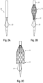
- a vascular prosthesis 10 loaded onto a release catheter 30 is shown schematically.
- the vascular prosthesis 10 is fixed at its distal end 11 via the fixing structures 19 provided there on the release catheter in appropriate receptacles and by covering a retraction cover 31.
- the vascular prosthesis 10 is also releasably fixed via its proximal end 12 to the release catheter 30 via a corresponding system (not shown).
- the completely fixed and compressed state of the vascular prosthesis 10 is in Fig. 2A shown.
- a central region of the vascular prosthesis 10 expands in a balloon shape, while the proximal and distal ends 12, 11 of the vascular prosthesis 10 are still fixed to the release catheter 30 (see Fig. 2B ).
- the vascular prosthesis 10 After the release of the proximal end 12 of the vascular prosthesis 10, it can expand, whereas the distal end 11 of the vascular prosthesis 10 is still fixed and compressed on the release catheter 30 and by the retraction sheath 31 (see Fig. 2C ). In this state, the vascular prosthesis 10 according to the invention can be released and positioned at the desired location, preferably behind a leaflet of the aortic valve (see also Fig. 3 ), preferably positioned behind the noncoronary cusp "NCC". This allows the anchoring structure 20 to be precisely aligned and prevent later proximal migration of the vascular prosthesis.
- the remaining vascular prosthesis can be released by completely retracting the retraction sheath 31.
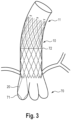
- the state of the vascular prosthesis 10 that is completely released in a heart 70 is in Fig. 3 shown, in which figure the vascular prosthesis is shown in dashed lines for better clarity. It can be seen here that anchoring structure 20 is positioned behind a leaflet of the aortic valve 71 while the rest of the vascular prosthesis 10 extends distally into the ascending aorta 72.
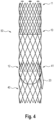
- Fig. 4 finally shows a system 50 according to the invention consisting of a vascular prosthesis 10 and a heart valve prosthesis 40 in assembled form, specifically outside the heart for better clarity.
- the heart valve prosthesis 40 can be inserted over it and released in such a way that The heart valve prosthesis 40 gets caught with its distal end 41 in the vascular prosthesis 10 at least partially at its proximal end 12 or is already fixed there by expansion.
Description
Die vorliegende Erfindung betrifft eine intraluminale Gefäßprothese zur Implantation in das Herz und/oder in Herzgefäße eines Patienten, insbesondere zur Verankerung im Bereich der Herzklappensegel; die Gefäßprothese weist ein distales und ein proximales Ende auf, sowie ein Stent-Gerüst und ein Prothesen-Material, mit welchem das Stent-Gerüst zumindest teilweise bedeckt ist, so dass ein gecoverter proximaler Abschnitt und ein nicht-gecoverter distaler Abschnitt gebildet wird.The present invention relates to an intraluminal vascular prosthesis for implantation into the heart and/or cardiac vessels of a patient, in particular for anchoring in the area of the heart valve leaflets; the vascular prosthesis has a distal and a proximal end, as well as a stent framework and a prosthesis material with which the stent framework is at least partially covered, so that a covered proximal section and a non-covered distal section are formed.
Allgemein werden intraluminale Gefäßprothesen im Stand der Technik insbesondere zur Behandlung von Aneurysmen bzw. zum Ersatz oder zur Unterstützung der natürlichen Gefäße oder sogar Herzklappen eingesetzt.In general, intraluminal vascular prostheses are used in the prior art in particular for the treatment of aneurysms or for replacing or supporting natural vessels or even heart valves.
Unter einem Aneursyma versteht man dabei eine Arterienerweiterung oder arterielle Aussackung, bei der sich infolge angeborener oder erworbener Wandveränderungen der Querschnitt von Blutgefäßen spindel- oder sackförmig lokal erweitert. Gefäßprothesen, die zur Behandlung von Aneurysmen eingesetzt werden. Dabei unterscheidet man zwischen einem echten Aneurysma, einem falschen Aneurysma und einem dissezierenden Aneurysma (Aneurysma dissecans), das als Folge einer Gefäßwanddissektion auftritt. Unter letzterer ist eine Aufspaltung der Wandschichten der Aorta zu verstehen, die meist durch einen Einriss der inneren Gefäßwand verursacht ist, mit nachfolgender Einblutung zwischen den Schichten. Zu den Risikofaktoren, die zu einer Aortendissektion führen können, zählen eine Strukturschwäche der Gefäßwand sowie die Arteriosklerose.An aneurysm is an arterial dilatation or arterial bulging in which the cross-section of blood vessels locally expands in a spindle or sac shape as a result of congenital or acquired wall changes. Vascular prostheses used to treat aneurysms. A distinction is made between a true aneurysm, a false aneurysm and a dissecting aneurysm ( aneurysma dissecans ), which occurs as a result of a vessel wall dissection. The latter refers to a splitting of the wall layers of the aorta, which is usually caused by a tear in the inner vessel wall, with subsequent bleeding between the layers. The risk factors that can lead to an aortic dissection include structural weakness of the vessel wall and arteriosclerosis.
Eine Aortendissektion ist in aller Regel unmittelbar lebensbedrohlich, weil sie zu einer Aortenruptur und zu akuten Durchblutungsstörungen verschiedener Organe führen kann. Eine unverzügliche Diagnostik ist deshalb bei dieser Krankheit von entscheidender Bedeutung.An aortic dissection is usually immediately life-threatening because it can lead to an aortic rupture and acute circulatory disorders in various organs. Immediate diagnosis is therefore crucial for this disease.
Statistisch gesehen treten Aortendissektionen am häufigsten (zu ca. 65%) nur wenige Zentimeter oberhalb der Aortenklappe, im ansteigenden Abschnitt der Aorta (Aorta ascendens) auf. Am zweithäufigsten (mit ca. 20%) entstehen Aortendissektionen unmittelbar nach Abgang der linken Schlüsselbeinarterie (Arteria subclavia sinistra) im absteigenden Abschnitt der Aorta (Aorta descendens). Des Weiteren sind der Aortenbogen mit 10 % oder die Bauchschlagader (Aorta abdominalis) mit 5 % betroffen.Statistically speaking, aortic dissections most often (approx. 65%) occur just a few centimeters above the aortic valve, in the ascending section of the aorta ( ascending aorta ). The second most common (approx. 20%) aortic dissections occur immediately after the departure of the left subclavian artery ( arteria subclavia sinistra ) in the descending section of the aorta ( aorta descendens ). Furthermore, the aortic arch is affected with 10% and the abdominal aorta with 5%.
Je nach lokalem Auftreten einer Dissektion, wird diese in "A" oder "B" klassifiziert, wobei sich eine strikte Unterscheidung zwischen Aortendissektionen mit und ohne Beteiligung der Aorta ascendens durchgesetzt hat. Dabei werden in der Regel Dissektionen, bei welchen der Eintritt im Bereich der Aorta ascendens liegt, als Typ A-Dissektionen bezeichnet, und Dissektionen, bei welchen der Eintritt ("Entry") distal der linken Arteria subclavia liegt als Typ-B-Dissektionen. Wie bereits erwähnt, ist die Aortendissektion ist einer der dringlichsten Notfälle in der Kardiologie und Herzchirurgie. Die hohe Sterblichkeit von ein bis zwei Prozent pro Stunde im Fall der Typ-A-Dissektion in der Akutphase zwingt zu einer unverzüglichen Klärung der Verdachtsdiagnose.Depending on the local occurrence of a dissection, it is classified as “A” or “B”, although a strict distinction has been made between aortic dissections with and without involvement of the ascending aorta . As a rule, dissections in which the entry is in the area of the ascending aorta are referred to as type A dissections, and dissections in which the entry is distal to the left subclavian artery are referred to as type B dissections. As already mentioned, aortic dissection is one of the most urgent emergencies in cardiology and heart surgery. The high mortality rate of one to two percent per hour in the acute phase of type A dissection requires immediate clarification of the suspected diagnosis.
Bei einer akuten Dissektion Typ A ist es vor diesem Hintergrund äußerst wichtig, die Gefahr einer Aortenruptur rasch zu bannen, wobei gegenwärtig üblicherweise künstliche Gefäßprothesen zum sofortigen operativen Ersatz der Aorta ascendens eingesetzt werden. Bei Notfalleinsätzen seltener sind hingegen Rekonstruktionen der Aortenklappe. In der Regel wird daher die Aortenklappe bei einer Dissektion der klappennahen Aortenabschnitte und bei Patienten mit einer angeborenen Bindegewebserkrankung entfernt und eine Prothese mit integrierter Klappenprothese eingesetzt, an die auch die Herzkranzgefäße wieder "angeschlossen" werden. Grundsätzlich werden dabei zwei Arten von Herzklappenprothesen unterschieden, mechanische Klappen einerseits, die künstlich hergestellt werden und zum größten Teil aus Metall bestehen, sowie biologische Klappen andererseits, die als Transplantate von Mensch oder Tier zur Verfügung stehen.Against this background, in the case of an acute type A dissection, it is extremely important to quickly eliminate the risk of aortic rupture, although artificial vascular prostheses are currently usually used for immediate surgical replacement of the ascending aorta . However, reconstructions of the aortic valve are less common in emergency operations. As a rule, the aortic valve is therefore removed in the event of a dissection of the aortic sections near the valve and in patients with a congenital connective tissue disease and a prosthesis with an integrated valve prosthesis is inserted, to which the coronary arteries are also "connected" again. A basic distinction is made between two types of heart valve prostheses: mechanical valves, which are manufactured artificially and consist largely of metal, and biological valves, which are available as transplants from humans or animals.
Die künstlichen Prothesen können dabei entweder offen-chirurgisch oder minimal-invasiv eingesetzt werden.The artificial prostheses can be used either open surgically or minimally invasively.
Die korrekte Einsetzung der Prothese an die zu behandelnde Stelle stellt regelmäßig eine Herausforderung an den behandelnden Arzt dar, da bereits ein geringfügiges Verrutschen der Prothese die "stillgelegte" Aussackung wieder in den Blutkreislauf einbeziehen kann, und dadurch die Gefahr einer Ruptur erneut gegeben ist. Die Gefahr des Verrutschens bzw. einer Migration der Prothese ist auch nach deren Platzierung gegeben, insbesondere vor dem Hintergrund der natürlichen Herzbewegung. Aus diesen Gründen wird die Prothese in der Regel proximal und distal durch Nähte an der Gefäßwand fixiert. Diese Naht-Fixierung hat allerdings den Nachteil, dass die oftmals ohnehin beeinträchtigten Gefäßwände weiter strapaziert werden. Auch ist bei Patienten mit stark beschädigter Gefäßwand ein Fixieren mittels Nähten nicht möglich.Correct insertion of the prosthesis into the area to be treated regularly represents a challenge for the treating physician, as even a slight slip of the prosthesis can involve the "decommissioned" bulge back into the bloodstream, thereby re-introducing the risk of rupture. There is a risk of the prosthesis slipping or migrating even after it has been placed, particularly given the natural movement of the heart. For these reasons, the prosthesis is usually fixed to the vessel wall proximally and distally using sutures. However, this suture fixation has the disadvantage that the vessel walls, which are often already impaired, are further stressed. In patients with severely damaged vascular walls, fixation with sutures is also not possible.
Die
Auch die
Vor diesem Hintergrund ist Aufgabe der vorliegenden Erfindung, eine Vorrichtung bereitzustellen, mit welcher die beschriebenen Nachteile überwunden und Herzklappenprothesen sicher im Herzen, insbesondere bei Typ-A-Dissektionen, fixiert werden können.Against this background, the object of the present invention is to provide a device with which the disadvantages described can be overcome and heart valve prostheses can be securely fixed in the heart, especially in type A dissections.
Erfindungsgemäß wird dies durch eine Gefäßprothese der eingangs genannten Art gelöst, wobei die Gefäßprothese am proximalen Ende zumindest eine bis drei ängliche drahtförmige Verankerungsstruktur(en) aufweist, welche im Wesentlichen schlaufenförmig ist/sind, und welche jeweils mit zwei Enden am Stent-Gerüst fixiert ist/sind und welche jeweils mit ihrem proximalen Ende in Form einer Schlaufe in proximale Richtung weisend und über das proximale Ende des Stent-Gerüsts hinaus ragend positioniert ist/sind.According to the invention, this is achieved by a vascular prosthesis of the type mentioned at the outset, with the vascular prosthesis at least at the proximal end one to three long wire-shaped anchoring structure(s), which is/are essentially loop-shaped, and which is/are each fixed with two ends to the stent framework and which each has its proximal end pointing in the proximal direction in the form of a loop and over the proximal end of the stent framework is/are positioned projecting out.
Die der Erfindung zugrunde liegende Aufgabe wird auf dieser Weise vollkommen gelöst.The object on which the invention is based is completely achieved in this way.
Mit der am proximalen Ende vorgesehenen spezifischen Verankerungsstruktur der Gefäßprothese wird erreicht, dass diese sicher im Herzen verankert wird, ohne die natürliche Funktion der Herzklappen zu stören. Dies wird durch die spezifische Ausgestaltung der Verankerungsstruktur erreicht, die sich am proximalen Ende schlaufenartig bzw. bogenartig in proximale Richtung erstreckt. Über dieser Verankerungsstruktur kann die Gefäßprothese gezielt und sicher positioniert werden.The specific anchoring structure of the vascular prosthesis provided at the proximal end ensures that it is securely anchored in the heart without disrupting the natural function of the heart valves. This is achieved by the specific design of the anchoring structure, which extends in a loop-like or arch-like manner in the proximal direction at the proximal end. The vascular prosthesis can be positioned specifically and safely via this anchoring structure.
Die erfindungsgemäße Gefäßprothese dient dabei dann als Anker für eine separat einzubringende Herzklappenprothese, die zumindest teilweise oder überschneidend in der im Gefäß verankerten erfindungsgemäßen Gefäßprothese freigesetzt wird, und die der Unterstützung oder dem Ersatz der natürlichen Gefäßprothese dient.The vascular prosthesis according to the invention then serves as an anchor for a heart valve prosthesis to be inserted separately, which is released at least partially or overlappingly in the vascular prosthesis according to the invention anchored in the vessel, and which serves to support or replace the natural vascular prosthesis.
Dabei kann jede Herzklappenprothese über die erfindungsgemäße Gefäßprothese eingesetzt werden, welche Herzklappenprothese vorzugsweise ein selbstexpandierendes Gerüst mit darin angebrachten Klappen aufweist. Beispielhaft wird auf die
Mit der Verankerungsstruktur wird erreicht, dass ein zusätzliches Vernähen der Gefäßprothese bzw. der Herzklappenprothese an den Gefäßen und damit eine Belastung dieser vermieden werden kann. Die erfindungsgemäße Gefäßprothese stellt damit eine Art Ankerstruktur bzw. Aufnahmestruktur dar, über welchen die in einem zweiten Schritt einzuführende Herzklappenprothese sicher im Herzen verankert werden kann. Dadurch wird auch vermieden, dass an der Herzklappenprothese selber komplizierte Fixierungselemente vorgesehen sein müssen, um diese sicher im Herzen zu fixieren.The anchoring structure ensures that additional suturing of the vascular prosthesis or the heart valve prosthesis to the vessels and thus strain on them can be avoided. The vascular prosthesis according to the invention thus represents a type of anchor structure or receiving structure, via which the heart valve prosthesis to be inserted in a second step can be securely anchored in the heart. This also avoids having to provide complicated fixation elements on the heart valve prosthesis itself in order to securely fix it in the heart.
Die Verankerungsstruktur wird dabei vorzugsweise hinter einem Segel der Aortenklappe, vorzugsweise das nonkoronare Segel bzw. "non coronary cusp "NCC", positioniert, während die Gefäßprothese selber mit ihrem restlichen Körper noch im Katheter über eine Rückzugshülle oder eine andere Komprimierung fixiert ist. Dadurch kann die Verankerungsstruktur genau ausgerichtet werden und eine spätere proximale Migration der Prothese verhindern.The anchoring structure is preferably positioned behind a leaflet of the aortic valve, preferably the noncoronary leaflet or "non coronary cusp "NCC", while the vascular prosthesis itself with the rest of its body is still fixed in the catheter via a retraction sheath or other compression. This can the anchoring structure can be precisely aligned and prevent subsequent proximal migration of the prosthesis.
Die erfindungsgemäße Gefäßprothese dient dabei vorzugsweise der Behandlung von Aortendissektionen vom Typus A, und wird über eine kathetergeführte Anwendung minimal-invasiv eingebracht.The vascular prosthesis according to the invention is preferably used to treat type A aortic dissections and is introduced in a minimally invasive manner via a catheter-guided application.
Grundsätzlich werden bei Gefäßprothesen bzw. endoluminalen Stentgrafts allgemein sowie vorliegend zur Bezeichnung der jeweiligen Enden der Gefäßprothese die Begriffe "distal" und "proximal" verwendet, wobei der Begriff "distal" der Teil bzw. das Ende bezeichnet wird, der/das in Bezug auf den Blutstrom weiter stromabwärts liegt. Der Begriff "proximal" hingegen bezeichnet, wieder in Bezug auf den Blutstrom, einen Teil bzw. das Ende, der/das in Bezug auf den Blutstrom weiter stromaufwärts liegt. Anders ausgedrückt bedeutet der Begriff "distal" in Richtung des Blutstroms, und der Begriff "proximal" der Richtung des Blutstroms entgegengesetzt. Bei Kathetern hingegen, bzw. Einführsystemen, mit welchen die Gefäßprothesen in die Gefäße eingebracht werden, bezeichnet der Begriff "distal" das Ende des Katheters bzw. Einführsystems, das in den Patienten eingeführt wird, bzw. das vom Anwender ausgesehen am Entferntesten liegt, und der Begriff "proximal" das Ende, das sich dem Anwender näher zugewandt.Basically, in the case of vascular prostheses or endoluminal stent grafts, the terms “distal” and “proximal” are used in general and in this case to designate the respective ends of the vascular prosthesis, whereby the term “distal” refers to the part or end that is in relation to further downstream in the bloodstream. The term "proximal", on the other hand, refers, again in relation to the blood stream, to a part or end that is further upstream in relation to the blood stream. In other words, the term "distal" means in the direction of the blood flow, and the term "proximal" means opposite to the direction of the blood flow. However, in the case of catheters or insertion systems with which the vascular prostheses are introduced into the vessels, the term "distal" refers to the end of the catheter or insertion system that is inserted into the patient or that is located furthest away from the user, and the term "proximal" means the end that is closer to the user.
Erfindungsgemäß bedeutet die Einteilung des Grundköpers der Gefäßprothese in einen proximalen Abschnitt und einen distalen Abschnitt, dass sich die jeweiligen Abschnitte durch eine voneinander unterschiedlichen Bauweise unterscheiden, und bspw. eine unterschiedliche Anzahl an Stent-Ringen oder unterschiedliche Länge des Stent-Gerüsts aufweisen, bzw. deren Stent-Ringe/Stent-Gerüst unterschiedliche Durchmesser aufweisen, und/oder von Prothesen-Material bedeckt ("gecovert") oder unbedeckt ("un-gecovert/nicht-gecovert") sind. Das Prothesen-Material kann dabei bspw. angenäht oder aufgeschrumpft oder anderweitig an dem Stent-Gerüst angebracht sein, und zwar entweder auf der der Gefäßwand zugewandten Seite des Stent-Gerüsts, oder auf der Innenseite, dem Blutfluss zugewandten Seite.According to the invention, the division of the base body of the vascular prosthesis into a proximal section and a distal section means that the respective sections differ from one another in their construction, and, for example, have a different number of stent rings or a different length of the stent framework, or whose stent rings/stent framework have different diameters and/or are covered (“covered”) or uncovered (“uncovered/not covered”) by prosthesis material. The prosthesis material can, for example, be sewn or shrunk or otherwise attached to the stent framework, either on the side of the stent framework facing the vessel wall, or on the inside, side facing the blood flow.
Der von Prothesenmaterial bedeckte, "gecoverte" proximale Abschnitt soll dabei die Dissektion überbrücken, der un-gecoverte distale Abschnitt wird distal der Dissektion gesetzt und dient überwiegend - wie auch der gecoverte Abschnitt - der Fixierung der Gefäßprothese im Gefäß.The "covered" proximal section covered by prosthesis material is intended to bridge the dissection, the uncovered distal section is placed distal to the dissection and serves primarily - like the covered section - to fix the vascular prosthesis in the vessel.
Eine "drahtförmige, im Wesentlichen schlaufenförmige" Verankerungsstruktur bedeutet vorliegend, dass die Struktur durch Biegen eines Drahtes oder drahtähnlicher Struktur in einen Bogen gebildet wird, mit zwei "freien" Enden sowie einem Bogen-Ende, der den beiden freien Enden gegenüber liegt. "Freie Enden" bedeutet dabei, dass diese nicht - wie der Bogenabschnitt - direkt bzw. in einem Stück miteinander verbunden sind.A "wire-shaped, substantially loop-shaped" anchoring structure herein means that the structure is formed by bending a wire or wire-like structure into an arch, having two "free" ends and an arch end opposite the two free ends. “Free ends” means that these are not connected to one another directly or in one piece, like the arch section.
"Im Wesentlichen" bedeutet ferner, dass die Verankerungsstruktur nicht exakt schlaufenförmig-rund gebogen sein muss, sondern lediglich nach Art einer Schlaufe geführt sein soll und von einem Fachmann noch als solche betrachtet wird.“Essentially” also means that the anchoring structure does not have to be bent exactly in a loop-shaped round, but should only be guided in the manner of a loop and is still viewed as such by a person skilled in the art.
Erfindungsgemäß ragt die Verankerungsstruktur über das proximale Ende der Gefäßprothese in proximale Richtung hinaus, wobei sich die Verankerungsstruktur mit zwischen ca. 1 cm und 3 cm, vorzugsweise mit ca. 1, 1,5, 2, 2,5 oder 3 cm über das proximale Ende der Gefäßprothese hinaus erstreckt.According to the invention, the anchoring structure projects beyond the proximal end of the vascular prosthesis in the proximal direction, with the anchoring structure being between approximately 1 cm and 3 cm, preferably approximately 1, 1.5, 2, 2.5 or 3 cm extends beyond the proximal end of the vascular prosthesis.
Das Prothesenmaterial kann ein Material aufweisen oder aus diesem gebildet sein, das ausgewählt ist aus Polyester, Polyurethan, Polystyrol, Polytetrafluorethylen, ultrahochmolekulargewichtiges Polyethylen (UHMPE), oder Mischungen davon.The prosthetic material may include or be formed from a material selected from polyester, polyurethane, polystyrene, polytetrafluoroethylene, ultra-high molecular weight polyethylene (UHMPE), or mixtures thereof.
Unter einem "Stent-Gerüst" wird vorliegend jede Drahtprothese in Röhrchenform bzw. Zylinderform aus Metall oder Kunstfaser verstanden, das vorzugsweise selbstexpandierend ist, und ein gitter- oder netzartiges Gerüst bildet, an welches ggf. Prothesenmaterial angebracht werden kann. Hierunter kann bspw. ein Drahtgeflecht zu verstehen sein, oder aber hintereinander angeordnete, mäanderförmig umlaufende, sogenannte Stent-Federn/Stent-Ringe, die ggf. über Verbindungsstützen aus Draht miteinander verbunden sind, oder die lediglich über das Implantatmaterial miteinander verbunden sind. Das Stent- Gerüst ist dabei üblicherweise aus einem Shape-Memory-Material, in der Regel aus Nitinol, wodurch das Gerüst nach Einbringung in ein Gefäß zur 2Freisetzung wieder in den expandierten Zustand übergehen und das Gefäßimplantat dadurch "aufspannen" kann.In the present case, a “stent framework” is understood to mean any wire prosthesis in the form of a tube or cylinder made of metal or synthetic fiber, which is preferably self-expanding and forms a lattice or net-like framework to which prosthetic material can be attached if necessary. This can be understood to mean, for example, a wire mesh, or so-called stent springs/stent rings arranged one behind the other in a meandering shape, which are possibly connected to one another via connecting supports made of wire, or which are only connected to one another via the implant material. The stent framework is usually made of a shape memory material, usually made of Nitinol, whereby the framework can return to the expanded state after being introduced into a vessel for release and can thereby "clamp" the vascular implant.
Entsprechend ist gemäß einer Ausführungsform der vorliegenden Erfindung das Stent-Gerüst ein laser-geschnittenes Stent-Gerüst oder ein geflochtenes oder gewebtes Stent-Gerüst, oder besteht, ggf. nur teilweise, (bspw. im proximalen Abschnitt oder im distalen Abschnitt) aus einzelnen, nur über das Prothesenmaterial und nicht untereinander (durch Stege o.ä.) verbundenen Stentringen.Accordingly, according to one embodiment of the present invention, the stent framework is a laser-cut stent framework or a braided or woven stent framework, or consists, if necessary only partially, (e.g. in the proximal section or in the distal section) of individual, only via the prosthesis material and not between the stent rings connected to each other (by bars or similar).
Dem Fachmann wird dabei unter Berücksichtigung der jeweils zu behandelnden Dissektion und des Gefäßzustandes klar und offensichtlich sein, welches Stent-Gerüst eingesetzt wird, um die bestmöglichste Verwirklichung der Erfindung zu erreichen. Entsprechend kann der proximale Abschnitt eine andere Stent-Gerüst-Struktur aufweisen als der distale Abschnitt der Gefäßprothese, oder aber beide weisen das gleiche Stent-Gerüst auf.It will be clear and obvious to the person skilled in the art, taking into account the dissection to be treated and the condition of the vessel, which stent framework is used in order to achieve the best possible implementation of the invention. Accordingly, the proximal section can have a different stent framework structure than the distal section of the vascular prosthesis, or both have the same stent framework.
Entsprechend weist in einer bevorzugten Ausführungsform das Stent-Gerüst rautenförmige Zellen auf bzw. besteht aus umlaufenden Reihen hintereinander angeordneter rautenförmiger Zellen, die über ihre Ecken aneinander angrenzen bzw. miteinander verbunden sind. An den äußersten Enden der Gefäßprothese befinden sich proximal und distal entsprechend freie "Ecken" der rautenförmigen Zellen.Accordingly, in a preferred embodiment, the stent framework has diamond-shaped cells or consists of circumferential rows of diamond-shaped cells arranged one behind the other, which adjoin one another or are connected to one another via their corners. At the extreme ends of the vascular prosthesis there are free “corners” of the diamond-shaped cells proximally and distally.
Gemäß einer Ausführungsform der erfindungsgemäßen Gefäßprothese sind am distalen Ende der Gefäßprothese Fixierstrukturen vorgesehen, über welche das distale Ende der Gefäßprothese an einem Freisetzungskatheter fixiert und komprimiert gehalten werden kann. Vorzugsweise sind die Fixierstrukturen T-förmige Verlängerungen von zumindest drei freien Ecken der rautenförmigen Zellen am distalen Ende. Diese T-förmigen Strukturen können in entsprechende T-förmige Aufnahmen in dem Freisetzungskatheter eingreifen. Eine Rückzugshülle, die dann über das distale Ende der Gefäßprothese geführt wird, hält die T-förmigen Fixierstrukturen in den T-förmigen Aufnahmen und fixiert damit das distale Ende der Gefäßprothese an dem Freisetzungskatheter. Bei einem Zurückziehen der die Gefäßprothese komprimierenden Rückzugshülle über die T-förmigen Aufnahme hinweg, können sich die T-förmigen Fixierstrukturen aus den Aufnahmen lösen, wodurch das distale Ende der Gefäßprothese freigesetzt wird.According to one embodiment of the vascular prosthesis according to the invention, fixing structures are provided at the distal end of the vascular prosthesis, via which the distal end of the vascular prosthesis can be fixed and kept compressed on a release catheter. Preferably, the fixation structures are T-shaped extensions of at least three free corners of the diamond-shaped cells at the distal end. These T-shaped structures can engage corresponding T-shaped receptacles in the delivery catheter. A retraction sleeve, which is then passed over the distal end of the vascular prosthesis, holds the T-shaped fixation structures in the T-shaped receptacles and thus fixes the distal end of the vascular prosthesis to the release catheter. When the retraction sleeve compressing the vascular prosthesis is pulled back beyond the T-shaped receptacle, the T-shaped fixation structures can detach from the receptacles, thereby releasing the distal end of the vascular prosthesis.
In einer Ausführungsform der erfindungsgemäßen Gefäßprothese ist bevorzugt, wenn die distalen Enden der drahtförmigen Verankerungsstruktur an unmittelbar benachbarten Ecken zweier rautenförmigen Zellen des proximalen Endes der Gefäßprothese positioniert sind.In one embodiment of the vascular prosthesis according to the invention, it is preferred if the distal ends of the wire-shaped anchoring structure are positioned at immediately adjacent corners of two diamond-shaped cells of the proximal end of the vascular prosthesis.
Mit dieser Ausführungsform wird erreicht, dass die Verankerungsstruktur stabil "aufgespannt" ist, und ein Vergrößern der Schlaufe, was ggf. eine Migration der Gefäßprothese zur Folge hätte, vermieden wird. Durch die vergleichsweise enge Fixierung der distalen Enden der Schlaufe wird über die proximale Schlaufe der Verankerungsstruktur dieser eine Steifigkeit verliehen, was wiederum eine stabile Verankerung der Gefäßprothese sichert.With this embodiment it is achieved that the anchoring structure is stably "stretched" and an enlargement of the loop, which would possibly result in migration of the vascular prosthesis, is avoided. Due to the comparatively tight fixation of the distal ends of the loop, the anchoring structure is given rigidity via the proximal loop, which in turn ensures stable anchoring of the vascular prosthesis.
Erfindungsgemäß ist vorgesehen, dass die drahtförmige Verankerungsstruktur an/in ihrem proximalen Ende bzw. Endbereich eine trapezförmige Erweiterung umfasst.According to the invention it is provided that the wire-shaped anchoring structure comprises a trapezoidal extension at/in its proximal end or end region.
Durch die trapezförmige Erweiterung erhält die Verankerungsstruktur eine zusätzliche Stabilität in diesem Bereich, mit welcher die sichere Verankerung in der Gefäßwand zusätzlich gesichert ist.The trapezoidal extension gives the anchoring structure additional stability in this area, which further ensures secure anchoring in the vessel wall.
Dabei ist gemäß einer Weiterbildung bevorzugt, wenn das äußerste proximale Ende der drahtförmigen Verankerungsstruktur tropfenförmig ist.According to a further development, it is preferred if the outermost proximal end of the wire-shaped anchoring structure is teardrop-shaped.
Diese Ausführungsform führt zu einer noch verbesserten Stabilität der Verankerungsstruktur. "Tropfenförmig" bedeutet dabei eine in proximale Richtung weisende zusätzlich zur Basis-Schlaufenform kleine aufgesetzte Schlaufe.This embodiment leads to even improved stability of the anchoring structure. “Teardrop-shaped” means a small attached loop pointing in the proximal direction in addition to the basic loop shape.
Bei der erfindungsgemäßen intraluminalen Gefäßprothese ist gemäß einer Ausführungsform bevorzugt, wenn das Stent-Gerüst und die Verankerungsstruktur einstückig ausgebildet sind.In the intraluminal vascular prosthesis according to the invention, according to one embodiment, it is preferred if the stent framework and the anchoring structure are formed in one piece.
Dabei bedeutet "einstückig", dass das Stent-Gerüst und die Verankerungsstruktur aus dem gleichen Draht bzw. aus dem gleichen gelaserten Rohr gefertigt wurden.“In one piece” means that the stent framework and the anchoring structure were made from the same wire or the same laser-cut tube.
Bei der erfindungsgemäßen Gefäßprothese sind am proximalen Ende des Stent-Gerüsts eine, zwei oder drei Verankerungsstrukturen vorgesehen.In the vascular prosthesis according to the invention, one, two or three anchoring structures are provided at the proximal end of the stent framework.
Durch das Vorsehen von mehr als einer Verankerungsstruktur kann die Gefäßprothese noch sicherer im Herzen fixiert werden. Die zusätzlichen Verankerungsstrukturen weisen dabei vorzugsweise die gleiche Struktur und Form auf, oder aber unterschiedliche Formen; allen gemein ist in diesen Fällen aber die schlaufenförmige Grundstruktur.By providing more than one anchoring structure, the vascular prosthesis can be fixed even more securely in the heart. The additional anchoring structures preferably have the same structure and shape, or different shapes; What they all have in common in these cases is the loop-shaped one Basic structure.
Gemäß einer Weiterbildung der erfindungsgemäßen intraluminalen Gefäßprothese ist bevorzugt, wenn das Stent-Gerüst und/oder die drahtförmige Verankerungsstruktur an ihrer der Gefäßwand abgewandten und/oder zugewandten Seite Haken oder Dornen aufweisen.According to a further development of the intraluminal vascular prosthesis according to the invention, it is preferred if the stent framework and/or the wire-shaped anchoring structure have hooks or thorns on their side facing away from and/or facing the vessel wall.
Mit diesen Ausführungsformen wird die Fixierung der Gefäßprothese im Gefäß weiter verstärkt und gesichert. Die Haken und/oder Dornen können aus dem gleichen Material wie die Verankerungsstruktur bzw. das Stent-Gerüst sein, oder aber aus unterschiedlichem Material.With these embodiments, the fixation of the vascular prosthesis in the vessel is further strengthened and secured. The hooks and/or thorns can be made of the same material as the anchoring structure or the stent framework, or of different materials.
In der Ausführungsform der an der Innenseite der Gefäßprothese vorgesehenen Haken/Dornen ist von Vorteil, dass über diese Haken bzw. Dornen die Verankerung einer hierin zumindest teilweise einzuführenden Herzklappenprothese noch weiter unterstützt wird. Zwar wird bereits mit dem teilweisen Freisetzen und "Aufspannen" der Herzklappenprothese in dem proximalen Ende der erfindungsgemäßen Gefäßprothese eine Verankerung dieser in der Gefäßprothese gesichert, die Dornen und Haken können aber die Verankerung der Herzklappe in der Gefäßprothese zusätzlich unterstützen.In the embodiment of the hooks/thorns provided on the inside of the vascular prosthesis, it is advantageous that these hooks or thorns further support the anchoring of a heart valve prosthesis to be at least partially inserted therein. Although the partial release and "clamping" of the heart valve prosthesis in the proximal end of the vascular prosthesis according to the invention ensures anchoring of the heart valve in the vascular prosthesis, the thorns and hooks can additionally support the anchoring of the heart valve in the vascular prosthesis.
Gemäß einer weiteren Ausführungsform der erfindungsgemäßen intraluminalen Gefäßprothese ist bevorzugt, wenn das Stent-Gerüst und/oder die drahtförmige Verankerungsstruktur Röntgenmarker umfasst.According to a further embodiment of the intraluminal vascular prosthesis according to the invention, it is preferred if the stent framework and/or the wire-shaped anchoring structure comprises X-ray markers.
Durch das Vorsehen von Röntgenmarkern an der Verankerungsstruktur wird dem behandelnden Arzt die korrekte Platzierung der Verankerungsstruktur und damit auch der Gefäßprothese insgesamt erleichtert, da er damit die Platzierung der Gefäßprothese im Herzen unter Röntgenkontrolle präzise vornehmen kann.The provision of X-ray markers on the anchoring structure makes it easier for the treating physician to correctly place the anchoring structure and thus also the vascular prosthesis as a whole, since he can thereby precisely place the vascular prosthesis in the heart under X-ray control.
Die erfindungsgemäße intraluminale Gefäßprothese weist insgesamt vorzugsweise einen Durchmesser von zwischen ca. 20 mm bis ca. 48 mm, vorzugsweise von zwischen 24 mm bis ca. 44 mm auf.The intraluminal vascular prosthesis according to the invention preferably has a total diameter of between approximately 20 mm to approximately 48 mm, preferably between 24 mm to approximately 44 mm.
Gemäß einer Ausführungsform ist der Durchmesser der Gefäßprothese dabei über deren Gesamtlänge im Wesentlichen konstant.According to one embodiment, the diameter of the vascular prosthesis is essentially constant over its entire length.
In einer Weiterbildung der erfindungsgemäßen intraluminalen Gefäßprothese ist vorgesehen, wenn diese ferner eine Herzklappenprothese umfasst, wobei die Herzklappenprothese derart ausgebildet ist, dass sie mit ihrem distalen Ende am proximalen Ende der intraluminalen Gefäßprothese freisetzbar ist und über diese im Bereich der Herzklappen fixierbar ist.In a further development of the intraluminal vascular prosthesis according to the invention, it is provided that it further comprises a heart valve prosthesis, the heart valve prosthesis being designed in such a way that its distal end can be released at the proximal end of the intraluminal vascular prosthesis and can be fixed in the area of the heart valves via this.
Bei dieser Ausführungsform liegen entsprechend zwei Prothesen vor, die gemeinsam ein erfindungsgemäßes System zur Behandlung einer Aortendissektion, insbesondere vom Typ A, darstellen: Mit der erfindungsgemäßen Gefäßprothese wird, wie weiter oben erwähnt, eine Verankerungsstruktur bereitgestellt, die in einem ersten Schritt in das Herz fixiert wird und über welche eine Herzklappenprothese, die in einem zweiten Schritt eingeführt wird, sicher im Herzen verankert werden kann. Die Gefahr des Verrutschens oder einer Migration der Herzklappenprothese wird dadurch vermieden, und gelichzeitig ein relativ einfacher Aufbau des Systems erreicht.In this embodiment, there are two prostheses, which together represent a system according to the invention for the treatment of an aortic dissection, in particular type A: With the vascular prosthesis according to the invention, as mentioned above, an anchoring structure is provided, which is fixed in the heart in a first step and through which a heart valve prosthesis, which is inserted in a second step, can be securely anchored in the heart. The risk of the heart valve prosthesis slipping or migrating is thereby avoided, and at the same time a relatively simple structure of the system is achieved.
Weitere Vorteile ergeben sich aus den Figuren und der nachstehenden Beschreibung bevorzugter Ausführungsbeispiele.Further advantages result from the figures and the following description of preferred exemplary embodiments.
Es versteht sich, dass die vorstehend genannten und die nachstehend noch zu erläuternden Merkmale nicht nur in der jeweils angegebenen Kombination, sondern auch in anderen Kombinationen oder in Alleinstellung verwendbar sind, ohne den Rahmen der vorliegenden Erfindung zu verlassen.It is understood that the features mentioned above and those to be explained below can be used not only in the combination specified in each case, but also in other combinations or alone, without departing from the scope of the present invention.
Ausführungsbeispiele der Erfindung sind in der Zeichnung dargestellt und werden in der nachfolgenden Beschreibung näher erläutert. Es zeigen:
- Fig. 1
- eine schematische Darstellung einer Ausführungsform einer erfindungsgemäßen Gefäßprothese, im nicht-eingeführten, expandierten Zustand in einer Ansicht der Längsseite;
- Fig. 2
- eine schematische Darstellung der schrittweisen Freisetzung der Gefäßprothese aus
Fig. 1 mit einem schematisch dargestellten Freisetzungskatheter; im vollständig geladenen Zustand (A); mit teilweise zurückgezogener Komprimierungsstruktur, aber mit immer noch am Freisetzungskatheter fixiertem proximalen und distalen Ende der Gefäßprothese (B); sowie mit freigesetztem proximalen Ende (C); - Fig. 3
- die schematische Darstellung einer im Herzgefäß vollständig freigesetzten Ausführungsform der erfindungsgemäßen Gefäßprothese;
- Fig. 4
- die schematische Darstellung eines erfindungsgemäßen Systems, mit einer in einer erfindungsgemäßen Gefäßprothese verankerten Herzklappenprothese, wobei die Darstellung außerhalb des Herzgefäßes gezeigt ist.
- Fig. 1
- a schematic representation of an embodiment of a vascular prosthesis according to the invention, in the non-inserted, expanded state in a view of the long side;
- Fig. 2
- a schematic representation of the gradual release of the vascular prosthesis
Fig. 1 with a delivery catheter shown schematically; in fully charged state ( A ); with the compression structure partially retracted, but with the proximal and distal ends of the vascular prosthesis still fixed to the delivery catheter ( B ); and with the proximal end released ( C ); - Fig. 3
- the schematic representation of an embodiment of the vascular prosthesis according to the invention that is completely released in the cardiac vessel;
- Fig. 4
- the schematic representation of a system according to the invention, with a heart valve prosthesis anchored in a vascular prosthesis according to the invention, the representation being shown outside the cardiac vessel.
In den Figuren werden gleiche Merkmale mit gleichen Bezugszeichen versehen, wobei aus Gründen der Übersichtlichkeit nicht in allen Figuren immer sämtliche Bezugszeichen angegeben sind.In the figures, the same features are given the same reference numerals, although for reasons of clarity not all reference numerals are always indicated in all figures.
In den
Erfindungsgemäß kann das Stent-Gerüst 14 ein Laser-geschnittenes Stent-Gerüst sein, oder aber ein aus mehreren Drähten geflochtenes oder gewebtes Stent-Gerüst, oder aber aus einzelnen, mäanderförmig umlaufenden, hintereinander angeordneten Stent-Ringen bestehen, die nur über das Prothesen-Material miteinander verbunden sind.According to the invention, the stent framework 14 can be a laser-cut stent framework, or one braided or woven from several wires Stent framework, or consist of individual, meandering stent rings arranged one behind the other, which are only connected to one another via the prosthesis material.
Die Gefäßprothese 10 weist in dem in den Figuren gezeigten Beispiel rautenförmige Zellen 18 auf, die reihenförmig das röhrchenförmige bzw. zylinderförmige Stent-Gerüst 14 bilden. Am distalen Ende 11 sind Fixierstrukturen 19 an drei freien Ecken der rautenförmigen Zellen 18 am distalen Ende 11 vorgesehen, über welche das distale Ende 11 der Gefäßprothese 10 in einem Freisetzungskatheter (nicht gezeigt) in entsprechenden Aufnahmen bzw. Aussparungen aufgenommen und über eine hierüber geführte Rückzugshülle (nicht gezeigt) am Freisetzungskatheter fixiert werden können. Die Fixierstrukturen 19 sind in der in
Am proximalen Ende 12 der Gefäßprothese 10 ist eine drahtförmige Verankerungsstruktur 20 vorgesehen, die in proximale Richtung 12' eine Schlaufe 21 bildet. Die Verankerungsstruktur 20 steht mit ca. 1/3 der Gesamtlänge der Gefäßprothese 10 über deren proximales Ende 12 hinaus.At the
Die Verankerungsstruktur 20 weist ein proximales Ende 22 auf, in dessen Bereich die Schlaufe 21 gebildet ist. Die Verankerungsstruktur 20 umfasst ferner zwei distale Enden 23 und 24, die an zwei freien Ecken 18', 18" der rautenförmigen Zellen 18 am proximalen Ende 12 der Gefäßprothese fixiert bzw. einstückig mit diesen ausgebildet sind.The anchoring
Wie
"Freie Enden" der rautenförmigen Zellen bedeuten dabei, wie auch für jede andere Ausführungsform der erfindungsgemäßen Gefäßprothese, das diese Ecken nicht mit einer weiteren rautenförmigen Zelle verbunden sind, sondern frei in die distale Richtung 11' oder proximale Richtung 12' ragen.“Free ends” of the diamond-shaped cells mean, as for any other embodiment of the vascular prosthesis according to the invention, that these corners are not connected to another diamond-shaped cell, but rather protrude freely in the distal direction 11 'or proximal direction 12'.
Die Verankerungsstruktur 20 weist, wie weiterhin in
Die Verankerungsstruktur 20 und das Stent-Gerüst 14 können einstückig gebildet sein, bspw. durch Laser-Schneiden eines entsprechenden Röhrchens bzw. Zylinders.The anchoring
Die Verankerungsstruktur 20 und/oder das Stent-Gerüst können an ihrer jeweils der Gefäßwand abgewandten Seite Haken oder Dornen aufweisen (nicht gezeigt), sowie einen oder mehrere Röntgenmarker umfassen.The anchoring
Der Durchmesser d der erfindungsgemäßen Gefäßprothese liegt vorzugsweise zwischen 20 mm und 48 mm, vorzugsweise zwischen ca. 24 mm und ca. 44 mm.The diameter d of the vascular prosthesis according to the invention is preferably between 20 mm and 48 mm, preferably between approximately 24 mm and approximately 44 mm.
In
Nach Zurückziehen der die Gefäßprothese komprimiert haltenden Rückzugshülle 31 expandiert sich ein mittlerer Bereich der Gefäßprothese 10 ballonförmig, während das proximale und das distale Ende 12, 11 der Gefäßprothese 10 noch am Freisetzungskatheter 30 fixiert sind (siehe
Nach der Freisetzung des proximalen Endes 12 der Gefäßprothese 10 kann dieses expandieren, wohingegen das distale Ende 11 der Gefäßprothese 10 noch am Freisetzungskatheter 30 und durch die Rückzugshülle 31 fixiert und komprimiert ist (siehe
Ist die Positionierung der Verankerungsstruktur 20 gesichert, kann die restliche Gefäßprothese durch vollständiges Rückziehen der Rückzugshülle 31 freigesetzt werden. Der in einem Herzen 70 vollständig freigesetzte Zustand der Gefäßprothese 10 ist in
Sobald die Gefäßprothese 10 als Anker im Herzen positioniert ist, kann die Herzklappenprothese 40 über diese eingeführt und derart freigesetzt werden, dass sich die Herzklappenprothese 40 mit ihrem distalen Ende 41 in der Gefäßprothese 10 zumindest teilweise an deren proximalen Ende 12 verhakt bzw. bereits durch Expansion dort fixiert. As soon as the
Claims (10)
- Intraluminal vascular prosthesis (10) for implantation into the heart (70) and/or into cardiovascular vessels of a patient, in particular for anchoring in the region of the cardiac valve leaflets (71), having a distal (11) and a proximal (12) end, wherein the distal end (11) lies further downstream in relation to the blood flow and the proximal end (12) lies further upstream in relation to the blood flow, the vascular prosthesis (10) having a stent support (14), and a prosthesis material (16) with which the stent support (14) is at least partially covered, such that a covered proximal portion (15) and a non-covered distal portion (17) are formed, characterized in that the vascular prosthesis (10) comprises, at the proximal end (12), at least one to three elongate wire-shaped anchoring structure(s) (20) which is/are substantially loop-shaped and which via two ends (23; 24) is/are fixed to the stent support (14) and which is/are positioned with its proximal end (22) in the form of a loop (21) pointing towards the proximal direction (12') and projecting beyond the proximal end (12) of the stent support (14), and wherein the wire-shaped anchoring structure (20) comprises a trapezoidal extension (25) in the region of the loop (21).
- The intraluminal vascular prosthesis (10) according to claim 1, characterized in that the distal ends (23; 24) of the wire-shaped anchoring structure (20) are positioned at immediately adjacent corners (18'; 18") of two diamond-shaped cells (18).
- The intraluminal vascular prosthesis (10) according to any of the preceding claims, characterized in that the outermost proximal end (26) of the wire-shaped anchoring structure is drop-shaped.
- The intraluminal vascular prosthesis (10) according to any of the preceding claims, characterized in that the stent support (14) is a laser-cut stent support or a braided or woven stent support.
- The intraluminal vascular prosthesis (10) according to any of the preceding claims, characterized in that the stent support (14) and the anchoring structure (20) are integrally formed.
- The intraluminal vascular prosthesis (10) according to any of the preceding claims, characterized in that the stent support (14) and/or the wire-shaped anchoring structure (20) have hooks or spikes on their respective side facing away from the vascular wall.
- The intraluminal vascular prosthesis (10) according to any of the preceding claims, characterized in that the stent support (14) has hooks or spikes on its side facing the vascular wall.
- The intraluminal vascular prosthesis (10) according to any of the preceding claims, characterized in that the stent support (14) and/or the wire-shaped anchoring structure comprises X-ray markers.
- The intraluminal vascular prosthesis (10) according to any of the preceding claims, characterized in that it has a diameter of between approx. 20 mm to approx. 48 mm, preferably of between 24 mm to approx. 44 mm.
- The intraluminal vascular prosthesis (10) according to any of claims 1 to 9, further comprising a heart valve prosthesis (40), wherein the heart valve prosthesis (40) is designed such that it can be released with its distal end (41) at the proximal end (12) of the intraluminal vascular prosthesis (10) and can be fixed via the latter in the region of the heart valves.
Applications Claiming Priority (2)
| Application Number | Priority Date | Filing Date | Title |
|---|---|---|---|
| DE202016105963.1U DE202016105963U1 (en) | 2016-10-24 | 2016-10-24 | Intraluminal vascular prosthesis for implantation in the heart or cardiac vessels of a patient |
| PCT/EP2017/077044 WO2018077821A1 (en) | 2016-10-24 | 2017-10-24 | Intraluminal vessel prosthesis for implantation into the heart or cardiac vessels of a patient |
Publications (3)
| Publication Number | Publication Date |
|---|---|
| EP3528748A1 EP3528748A1 (en) | 2019-08-28 |
| EP3528748B1 EP3528748B1 (en) | 2021-01-20 |
| EP3528748B2 true EP3528748B2 (en) | 2024-02-14 |
Family
ID=60164699
Family Applications (1)
| Application Number | Title | Priority Date | Filing Date |
|---|---|---|---|
| EP17788212.3A Active EP3528748B2 (en) | 2016-10-24 | 2017-10-24 | Intraluminal vessel prosthesis for implantation into the heart or cardiac vessels of a patient |
Country Status (7)
| Country | Link |
|---|---|
| US (1) | US11007055B2 (en) |
| EP (1) | EP3528748B2 (en) |
| JP (1) | JP6831009B2 (en) |
| CN (1) | CN109862852B (en) |
| DE (1) | DE202016105963U1 (en) |
| ES (1) | ES2866932T3 (en) |
| WO (1) | WO2018077821A1 (en) |
Families Citing this family (18)
| Publication number | Priority date | Publication date | Assignee | Title |
|---|---|---|---|---|
| US8579964B2 (en) | 2010-05-05 | 2013-11-12 | Neovasc Inc. | Transcatheter mitral valve prosthesis |
| US9308087B2 (en) | 2011-04-28 | 2016-04-12 | Neovasc Tiara Inc. | Sequentially deployed transcatheter mitral valve prosthesis |
| US9554897B2 (en) | 2011-04-28 | 2017-01-31 | Neovasc Tiara Inc. | Methods and apparatus for engaging a valve prosthesis with tissue |
| US9345573B2 (en) | 2012-05-30 | 2016-05-24 | Neovasc Tiara Inc. | Methods and apparatus for loading a prosthesis onto a delivery system |
| US9572665B2 (en) | 2013-04-04 | 2017-02-21 | Neovasc Tiara Inc. | Methods and apparatus for delivering a prosthetic valve to a beating heart |
| BR102015011376B1 (en) | 2015-05-18 | 2023-04-04 | Murilo Pundek Rocha | IMPLANTABLE ARTIFICIAL BRONCHI |
| WO2017127939A1 (en) | 2016-01-29 | 2017-08-03 | Neovasc Tiara Inc. | Prosthetic valve for avoiding obstruction of outflow |
| CN113893064A (en) | 2016-11-21 | 2022-01-07 | 内奥瓦斯克迪亚拉公司 | Methods and systems for rapid retrieval of transcatheter heart valve delivery systems |
| EP3672530A4 (en) | 2017-08-25 | 2021-04-14 | Neovasc Tiara Inc. | Sequentially deployed transcatheter mitral valve prosthesis |
| US11737872B2 (en) | 2018-11-08 | 2023-08-29 | Neovasc Tiara Inc. | Ventricular deployment of a transcatheter mitral valve prosthesis |
| WO2020191203A1 (en) | 2019-03-20 | 2020-09-24 | inQB8 Medical Technologies, LLC | Aortic dissection implant |
| JP7438236B2 (en) | 2019-04-01 | 2024-02-26 | ニオバスク ティアラ インコーポレイテッド | Controllably deployable prosthetic valve |
| EP3952792A4 (en) | 2019-04-10 | 2023-01-04 | Neovasc Tiara Inc. | Prosthetic valve with natural blood flow |
| US11779742B2 (en) | 2019-05-20 | 2023-10-10 | Neovasc Tiara Inc. | Introducer with hemostasis mechanism |
| AU2020295566B2 (en) | 2019-06-20 | 2023-07-20 | Neovasc Tiara Inc. | Low profile prosthetic mitral valve |
| USD902407S1 (en) * | 2019-11-19 | 2020-11-17 | Pulmair Medical, Inc. | Implantable artificial bronchus |
| USD954953S1 (en) | 2020-11-03 | 2022-06-14 | Pulmair Medical, Inc. | Implantable artificial bronchus |
| USD1014758S1 (en) | 2023-04-19 | 2024-02-13 | Pulmair Medical, Inc. | Implantable artificial bronchus |
Citations (18)
| Publication number | Priority date | Publication date | Assignee | Title |
|---|---|---|---|---|
| EP0657147A2 (en) † | 1993-11-04 | 1995-06-14 | C.R. Bard, Inc. | Non-migrating vascular prosthesis and minimally invasive placement system therefor |
| US20030040792A1 (en) † | 2000-09-12 | 2003-02-27 | Shlomo Gabbay | Heart valve prosthesis and sutureless implantation of a heart valve prosthesis |
| US6579314B1 (en) † | 1995-03-10 | 2003-06-17 | C.R. Bard, Inc. | Covered stent with encapsulated ends |
| US20030236568A1 (en) † | 2002-05-10 | 2003-12-25 | Hikmat Hojeibane | Multi-lobed frame based unidirectional flow prosthetic implant |
| US20040082989A1 (en) † | 2002-08-20 | 2004-04-29 | Cook Incorporated | Stent graft with improved proximal end |
| US20040236411A1 (en) † | 2001-07-19 | 2004-11-25 | The Cleveland Clinic Foundation | Prosthetic cardiac valve and method for making same |
| US20050096734A1 (en) † | 2003-10-31 | 2005-05-05 | Majercak David C. | Implantable valvular prosthesis |
| US20050222674A1 (en) † | 2004-03-31 | 2005-10-06 | Med Institute, Inc. | Endoluminal graft with a prosthetic valve |
| US20080036113A1 (en) † | 2002-05-10 | 2008-02-14 | Iksoo Chun | Method of forming a tubular membrane on a structural frame |
| US20080177381A1 (en) † | 2007-01-19 | 2008-07-24 | The Cleveland Clinic Foundation | Method for implanting a cardiovascular valve |
| WO2010006627A1 (en) † | 2008-07-17 | 2010-01-21 | Nvt Ag | Cardiac valve prosthesis system |
| WO2011051043A1 (en) † | 2009-11-02 | 2011-05-05 | Symetis Sa | Aortic bioprosthesis and systems for delivery thereof |
| US20110125249A1 (en) † | 2009-11-19 | 2011-05-26 | Med Institute, Inc. | Stent Graft and Introducer Assembly |
| WO2012032187A1 (en) † | 2010-09-10 | 2012-03-15 | Symetis Sa | Valve replacement devices, delivery device for a valve replacement device and method of production of a valve replacement device |
| US20130090714A1 (en) † | 2011-10-11 | 2013-04-11 | Cook Medical Technologies Llc | Stent delivery, repositioning, and removal system |
| US20140039614A1 (en) † | 2007-08-21 | 2014-02-06 | Symetis Sa | Stent-Valves For Valve Replacement and Associated Methods and Systems for Surgery |
| EP2926767A1 (en) † | 2003-12-23 | 2015-10-07 | Boston Scientific Scimed, Inc. | Repositionable heart valve |
| US9693860B2 (en) † | 2014-12-01 | 2017-07-04 | Medtronic, Inc. | Segmented transcatheter valve prosthesis having an unsupported valve segment |
Family Cites Families (24)
| Publication number | Priority date | Publication date | Assignee | Title |
|---|---|---|---|---|
| US20070043435A1 (en) * | 1999-11-17 | 2007-02-22 | Jacques Seguin | Non-cylindrical prosthetic valve system for transluminal delivery |
| US6458153B1 (en) * | 1999-12-31 | 2002-10-01 | Abps Venture One, Ltd. | Endoluminal cardiac and venous valve prostheses and methods of manufacture and delivery thereof |
| US6503272B2 (en) * | 2001-03-21 | 2003-01-07 | Cordis Corporation | Stent-based venous valves |
| DE10301026B4 (en) * | 2002-08-13 | 2014-10-30 | Jenavalve Technology Inc. | Device for anchoring and aligning heart valve prostheses |
| US7347869B2 (en) * | 2003-10-31 | 2008-03-25 | Cordis Corporation | Implantable valvular prosthesis |
| AU2007329243B2 (en) * | 2006-12-06 | 2014-04-03 | Medtronic CV Luxembourg S.a.r.l | System and method for transapical delivery of an annulus anchored self-expanding valve |
| WO2008097589A1 (en) * | 2007-02-05 | 2008-08-14 | Boston Scientific Limited | Percutaneous valve, system, and method |
| US9138315B2 (en) * | 2007-04-13 | 2015-09-22 | Jenavalve Technology Gmbh | Medical device for treating a heart valve insufficiency or stenosis |
| WO2008151204A1 (en) * | 2007-06-04 | 2008-12-11 | Sequent Medical Inc. | Methods and devices for treatment of vascular defects |
| EP3572044B1 (en) * | 2008-01-24 | 2021-07-28 | Medtronic, Inc. | Stents for prosthetic heart valves |
| PL2529701T3 (en) | 2011-06-01 | 2014-04-30 | Nvt Ag | Cardiac valve prosthesis deployment system |
| EP2822506A4 (en) * | 2012-03-05 | 2015-10-28 | Univ Pennsylvania | Superabsorbent coated stents for vascular reduction and for anchoring valve replacements |
| CN104470579B (en) * | 2012-06-06 | 2018-06-01 | 洋红医疗有限公司 | Artificial kidney valve |
| JP6563394B2 (en) * | 2013-08-30 | 2019-08-21 | イェーナヴァルヴ テクノロジー インコーポレイテッド | Radially foldable frame for an artificial valve and method for manufacturing the frame |
| US10646333B2 (en) * | 2013-10-24 | 2020-05-12 | Medtronic, Inc. | Two-piece valve prosthesis with anchor stent and valve component |
| US20150122687A1 (en) * | 2013-11-06 | 2015-05-07 | Edwards Lifesciences Corporation | Bioprosthetic heart valves having adaptive seals to minimize paravalvular leakage |
| EP2921139B1 (en) * | 2014-03-18 | 2018-11-21 | Nvt Ag | Heartvalve implant |
| EP3000437B1 (en) * | 2014-09-26 | 2018-05-30 | Nvt Ag | Implantable device for treating mitral valve regurgitation |
| CN104274259B (en) * | 2014-10-30 | 2016-06-01 | 宁波健世生物科技有限公司 | The artificial valve prosthese of a kind of band lobe leaf clamping device |
| EP3028668A1 (en) * | 2014-12-05 | 2016-06-08 | Nvt Ag | Prosthetic heart valve system and delivery system therefor |
| US10285809B2 (en) | 2015-03-06 | 2019-05-14 | Boston Scientific Scimed Inc. | TAVI anchoring assist device |
| KR20180067537A (en) * | 2015-10-13 | 2018-06-20 | 베나룸 메디컬, 엘엘씨 | Implantable Valves and Methods |
| PL3184081T3 (en) * | 2015-12-22 | 2021-10-04 | Medira Ag | Prosthetic mitral valve coaptation enhancement device |
| CN105496607A (en) * | 2016-01-11 | 2016-04-20 | 北京迈迪顶峰医疗科技有限公司 | Aortic valve device conveyed by catheter |
-
2016
- 2016-10-24 DE DE202016105963.1U patent/DE202016105963U1/en active Active
-
2017
- 2017-10-24 CN CN201780066034.2A patent/CN109862852B/en active Active
- 2017-10-24 WO PCT/EP2017/077044 patent/WO2018077821A1/en active Application Filing
- 2017-10-24 ES ES17788212T patent/ES2866932T3/en active Active
- 2017-10-24 EP EP17788212.3A patent/EP3528748B2/en active Active
- 2017-10-24 JP JP2019521708A patent/JP6831009B2/en active Active
-
2019
- 2019-04-23 US US16/391,405 patent/US11007055B2/en active Active
Patent Citations (18)
| Publication number | Priority date | Publication date | Assignee | Title |
|---|---|---|---|---|
| EP0657147A2 (en) † | 1993-11-04 | 1995-06-14 | C.R. Bard, Inc. | Non-migrating vascular prosthesis and minimally invasive placement system therefor |
| US6579314B1 (en) † | 1995-03-10 | 2003-06-17 | C.R. Bard, Inc. | Covered stent with encapsulated ends |
| US20030040792A1 (en) † | 2000-09-12 | 2003-02-27 | Shlomo Gabbay | Heart valve prosthesis and sutureless implantation of a heart valve prosthesis |
| US20040236411A1 (en) † | 2001-07-19 | 2004-11-25 | The Cleveland Clinic Foundation | Prosthetic cardiac valve and method for making same |
| US20080036113A1 (en) † | 2002-05-10 | 2008-02-14 | Iksoo Chun | Method of forming a tubular membrane on a structural frame |
| US20030236568A1 (en) † | 2002-05-10 | 2003-12-25 | Hikmat Hojeibane | Multi-lobed frame based unidirectional flow prosthetic implant |
| US20040082989A1 (en) † | 2002-08-20 | 2004-04-29 | Cook Incorporated | Stent graft with improved proximal end |
| US20050096734A1 (en) † | 2003-10-31 | 2005-05-05 | Majercak David C. | Implantable valvular prosthesis |
| EP2926767A1 (en) † | 2003-12-23 | 2015-10-07 | Boston Scientific Scimed, Inc. | Repositionable heart valve |
| US20050222674A1 (en) † | 2004-03-31 | 2005-10-06 | Med Institute, Inc. | Endoluminal graft with a prosthetic valve |
| US20080177381A1 (en) † | 2007-01-19 | 2008-07-24 | The Cleveland Clinic Foundation | Method for implanting a cardiovascular valve |
| US20140039614A1 (en) † | 2007-08-21 | 2014-02-06 | Symetis Sa | Stent-Valves For Valve Replacement and Associated Methods and Systems for Surgery |
| WO2010006627A1 (en) † | 2008-07-17 | 2010-01-21 | Nvt Ag | Cardiac valve prosthesis system |
| WO2011051043A1 (en) † | 2009-11-02 | 2011-05-05 | Symetis Sa | Aortic bioprosthesis and systems for delivery thereof |
| US20110125249A1 (en) † | 2009-11-19 | 2011-05-26 | Med Institute, Inc. | Stent Graft and Introducer Assembly |
| WO2012032187A1 (en) † | 2010-09-10 | 2012-03-15 | Symetis Sa | Valve replacement devices, delivery device for a valve replacement device and method of production of a valve replacement device |
| US20130090714A1 (en) † | 2011-10-11 | 2013-04-11 | Cook Medical Technologies Llc | Stent delivery, repositioning, and removal system |
| US9693860B2 (en) † | 2014-12-01 | 2017-07-04 | Medtronic, Inc. | Segmented transcatheter valve prosthesis having an unsupported valve segment |
Also Published As
| Publication number | Publication date |
|---|---|
| EP3528748A1 (en) | 2019-08-28 |
| JP6831009B2 (en) | 2021-02-17 |
| WO2018077821A1 (en) | 2018-05-03 |
| ES2866932T3 (en) | 2021-10-20 |
| DE202016105963U1 (en) | 2018-01-25 |
| JP2019531828A (en) | 2019-11-07 |
| CN109862852B (en) | 2021-04-09 |
| EP3528748B1 (en) | 2021-01-20 |
| US11007055B2 (en) | 2021-05-18 |
| CN109862852A (en) | 2019-06-07 |
| US20190254817A1 (en) | 2019-08-22 |
Similar Documents
| Publication | Publication Date | Title |
|---|---|---|
| EP3528748B2 (en) | Intraluminal vessel prosthesis for implantation into the heart or cardiac vessels of a patient | |
| DE60309843T2 (en) | DEVICE FOR ANCHORING ENDOLUMINAL PROTESTS | |
| EP3897454B1 (en) | Device for feeding and setting an implant into a blood vessel | |
| EP2809265B1 (en) | Modular stent graft | |
| EP2809267B1 (en) | Intraluminal vascular prosthesis | |
| EP3203931B1 (en) | Vascular prosthesis system | |
| EP3060177B1 (en) | Vascular implant having portions of different radial force | |
| EP3215055B1 (en) | Modular stent graft system | |
| WO2014026870A2 (en) | Implantable device for use in the human and/or animal body to replace an organ valve | |
| DE102017120819A1 (en) | Intraluminal vascular prosthesis system | |
| WO2014072501A2 (en) | Endovascular stent grafts, stent, stent-in-stent system, and kit | |
| WO2018220043A1 (en) | Stent graft with pockets | |
| EP2846732B1 (en) | In-situ fenestrated intraluminal vascular prosthesis | |
| EP2846731B1 (en) | Intraluminal vascular prosthesis having in-situ fenestration | |
| DE102017115898A1 (en) | Intraluminal vascular prosthesis | |
| WO2019072912A1 (en) | Expandable vascular implant | |
| DE102019121930A1 (en) | Vascular prosthesis |
Legal Events
| Date | Code | Title | Description |
|---|---|---|---|
| STAA | Information on the status of an ep patent application or granted ep patent |
Free format text: STATUS: UNKNOWN |
|
| STAA | Information on the status of an ep patent application or granted ep patent |
Free format text: STATUS: THE INTERNATIONAL PUBLICATION HAS BEEN MADE |
|
| PUAI | Public reference made under article 153(3) epc to a published international application that has entered the european phase |
Free format text: ORIGINAL CODE: 0009012 |
|
| STAA | Information on the status of an ep patent application or granted ep patent |
Free format text: STATUS: REQUEST FOR EXAMINATION WAS MADE |
|
| 17P | Request for examination filed |
Effective date: 20190328 |
|
| AK | Designated contracting states |
Kind code of ref document: A1 Designated state(s): AL AT BE BG CH CY CZ DE DK EE ES FI FR GB GR HR HU IE IS IT LI LT LU LV MC MK MT NL NO PL PT RO RS SE SI SK SM TR |
|
| AX | Request for extension of the european patent |
Extension state: BA ME |
|
| DAV | Request for validation of the european patent (deleted) | ||
| DAX | Request for extension of the european patent (deleted) | ||
| REG | Reference to a national code |
Ref country code: DE Ref legal event code: R079 Ref document number: 502017009160 Country of ref document: DE Free format text: PREVIOUS MAIN CLASS: A61F0002240000 Ipc: A61F0002070000 |
|
| GRAP | Despatch of communication of intention to grant a patent |
Free format text: ORIGINAL CODE: EPIDOSNIGR1 |
|
| STAA | Information on the status of an ep patent application or granted ep patent |
Free format text: STATUS: GRANT OF PATENT IS INTENDED |
|
| RIC1 | Information provided on ipc code assigned before grant |
Ipc: A61F 2/90 20130101ALN20200622BHEP Ipc: A61F 2/24 20060101ALI20200622BHEP Ipc: A61F 2/07 20130101AFI20200622BHEP |
|
| INTG | Intention to grant announced |
Effective date: 20200728 |
|
| GRAS | Grant fee paid |
Free format text: ORIGINAL CODE: EPIDOSNIGR3 |
|
| GRAA | (expected) grant |
Free format text: ORIGINAL CODE: 0009210 |
|
| STAA | Information on the status of an ep patent application or granted ep patent |
Free format text: STATUS: THE PATENT HAS BEEN GRANTED |
|
| AK | Designated contracting states |
Kind code of ref document: B1 Designated state(s): AL AT BE BG CH CY CZ DE DK EE ES FI FR GB GR HR HU IE IS IT LI LT LU LV MC MK MT NL NO PL PT RO RS SE SI SK SM TR |
|
| REG | Reference to a national code |
Ref country code: GB Ref legal event code: FG4D Free format text: NOT ENGLISH |
|
| REG | Reference to a national code |
Ref country code: CH Ref legal event code: NV Representative=s name: BOVARD AG PATENT- UND MARKENANWAELTE, CH Ref country code: CH Ref legal event code: EP |
|
| REG | Reference to a national code |
Ref country code: DE Ref legal event code: R096 Ref document number: 502017009160 Country of ref document: DE |
|
| REG | Reference to a national code |
Ref country code: AT Ref legal event code: REF Ref document number: 1355693 Country of ref document: AT Kind code of ref document: T Effective date: 20210215 |
|
| REG | Reference to a national code |
Ref country code: IE Ref legal event code: FG4D Free format text: LANGUAGE OF EP DOCUMENT: GERMAN |
|
| REG | Reference to a national code |
Ref country code: NL Ref legal event code: MP Effective date: 20210120 |
|
| REG | Reference to a national code |
Ref country code: LT Ref legal event code: MG9D |
|
| PG25 | Lapsed in a contracting state [announced via postgrant information from national office to epo] |
Ref country code: HR Free format text: LAPSE BECAUSE OF FAILURE TO SUBMIT A TRANSLATION OF THE DESCRIPTION OR TO PAY THE FEE WITHIN THE PRESCRIBED TIME-LIMIT Effective date: 20210120 Ref country code: FI Free format text: LAPSE BECAUSE OF FAILURE TO SUBMIT A TRANSLATION OF THE DESCRIPTION OR TO PAY THE FEE WITHIN THE PRESCRIBED TIME-LIMIT Effective date: 20210120 Ref country code: GR Free format text: LAPSE BECAUSE OF FAILURE TO SUBMIT A TRANSLATION OF THE DESCRIPTION OR TO PAY THE FEE WITHIN THE PRESCRIBED TIME-LIMIT Effective date: 20210421 Ref country code: NO Free format text: LAPSE BECAUSE OF FAILURE TO SUBMIT A TRANSLATION OF THE DESCRIPTION OR TO PAY THE FEE WITHIN THE PRESCRIBED TIME-LIMIT Effective date: 20210420 Ref country code: PT Free format text: LAPSE BECAUSE OF FAILURE TO SUBMIT A TRANSLATION OF THE DESCRIPTION OR TO PAY THE FEE WITHIN THE PRESCRIBED TIME-LIMIT Effective date: 20210520 Ref country code: BG Free format text: LAPSE BECAUSE OF FAILURE TO SUBMIT A TRANSLATION OF THE DESCRIPTION OR TO PAY THE FEE WITHIN THE PRESCRIBED TIME-LIMIT Effective date: 20210420 Ref country code: LT Free format text: LAPSE BECAUSE OF FAILURE TO SUBMIT A TRANSLATION OF THE DESCRIPTION OR TO PAY THE FEE WITHIN THE PRESCRIBED TIME-LIMIT Effective date: 20210120 |
|
| PG25 | Lapsed in a contracting state [announced via postgrant information from national office to epo] |
Ref country code: SE Free format text: LAPSE BECAUSE OF FAILURE TO SUBMIT A TRANSLATION OF THE DESCRIPTION OR TO PAY THE FEE WITHIN THE PRESCRIBED TIME-LIMIT Effective date: 20210120 Ref country code: RS Free format text: LAPSE BECAUSE OF FAILURE TO SUBMIT A TRANSLATION OF THE DESCRIPTION OR TO PAY THE FEE WITHIN THE PRESCRIBED TIME-LIMIT Effective date: 20210120 Ref country code: LV Free format text: LAPSE BECAUSE OF FAILURE TO SUBMIT A TRANSLATION OF THE DESCRIPTION OR TO PAY THE FEE WITHIN THE PRESCRIBED TIME-LIMIT Effective date: 20210120 Ref country code: PL Free format text: LAPSE BECAUSE OF FAILURE TO SUBMIT A TRANSLATION OF THE DESCRIPTION OR TO PAY THE FEE WITHIN THE PRESCRIBED TIME-LIMIT Effective date: 20210120 |
|
| PG25 | Lapsed in a contracting state [announced via postgrant information from national office to epo] |
Ref country code: IS Free format text: LAPSE BECAUSE OF FAILURE TO SUBMIT A TRANSLATION OF THE DESCRIPTION OR TO PAY THE FEE WITHIN THE PRESCRIBED TIME-LIMIT Effective date: 20210520 |
|
| REG | Reference to a national code |
Ref country code: DE Ref legal event code: R026 Ref document number: 502017009160 Country of ref document: DE |
|
| REG | Reference to a national code |
Ref country code: ES Ref legal event code: FG2A Ref document number: 2866932 Country of ref document: ES Kind code of ref document: T3 Effective date: 20211020 |
|
| PLBI | Opposition filed |
Free format text: ORIGINAL CODE: 0009260 |
|
| PG25 | Lapsed in a contracting state [announced via postgrant information from national office to epo] |
Ref country code: SM Free format text: LAPSE BECAUSE OF FAILURE TO SUBMIT A TRANSLATION OF THE DESCRIPTION OR TO PAY THE FEE WITHIN THE PRESCRIBED TIME-LIMIT Effective date: 20210120 Ref country code: CZ Free format text: LAPSE BECAUSE OF FAILURE TO SUBMIT A TRANSLATION OF THE DESCRIPTION OR TO PAY THE FEE WITHIN THE PRESCRIBED TIME-LIMIT Effective date: 20210120 Ref country code: EE Free format text: LAPSE BECAUSE OF FAILURE TO SUBMIT A TRANSLATION OF THE DESCRIPTION OR TO PAY THE FEE WITHIN THE PRESCRIBED TIME-LIMIT Effective date: 20210120 |
|
| PLAX | Notice of opposition and request to file observation + time limit sent |
Free format text: ORIGINAL CODE: EPIDOSNOBS2 |
|
| 26 | Opposition filed |
Opponent name: DAUSTER, KATJA Effective date: 20211018 |
|
| PG25 | Lapsed in a contracting state [announced via postgrant information from national office to epo] |
Ref country code: RO Free format text: LAPSE BECAUSE OF FAILURE TO SUBMIT A TRANSLATION OF THE DESCRIPTION OR TO PAY THE FEE WITHIN THE PRESCRIBED TIME-LIMIT Effective date: 20210120 Ref country code: SK Free format text: LAPSE BECAUSE OF FAILURE TO SUBMIT A TRANSLATION OF THE DESCRIPTION OR TO PAY THE FEE WITHIN THE PRESCRIBED TIME-LIMIT Effective date: 20210120 Ref country code: DK Free format text: LAPSE BECAUSE OF FAILURE TO SUBMIT A TRANSLATION OF THE DESCRIPTION OR TO PAY THE FEE WITHIN THE PRESCRIBED TIME-LIMIT Effective date: 20210120 |
|
| PG25 | Lapsed in a contracting state [announced via postgrant information from national office to epo] |
Ref country code: AL Free format text: LAPSE BECAUSE OF FAILURE TO SUBMIT A TRANSLATION OF THE DESCRIPTION OR TO PAY THE FEE WITHIN THE PRESCRIBED TIME-LIMIT Effective date: 20210120 |
|
| PG25 | Lapsed in a contracting state [announced via postgrant information from national office to epo] |
Ref country code: SI Free format text: LAPSE BECAUSE OF FAILURE TO SUBMIT A TRANSLATION OF THE DESCRIPTION OR TO PAY THE FEE WITHIN THE PRESCRIBED TIME-LIMIT Effective date: 20210120 |
|
| PLBB | Reply of patent proprietor to notice(s) of opposition received |
Free format text: ORIGINAL CODE: EPIDOSNOBS3 |
|
| PG25 | Lapsed in a contracting state [announced via postgrant information from national office to epo] |
Ref country code: IS Free format text: LAPSE BECAUSE OF FAILURE TO SUBMIT A TRANSLATION OF THE DESCRIPTION OR TO PAY THE FEE WITHIN THE PRESCRIBED TIME-LIMIT Effective date: 20210520 |
|
| REG | Reference to a national code |
Ref country code: BE Ref legal event code: MM Effective date: 20211031 |
|
| PG25 | Lapsed in a contracting state [announced via postgrant information from national office to epo] |
Ref country code: MC Free format text: LAPSE BECAUSE OF FAILURE TO SUBMIT A TRANSLATION OF THE DESCRIPTION OR TO PAY THE FEE WITHIN THE PRESCRIBED TIME-LIMIT Effective date: 20210120 |
|
| PG25 | Lapsed in a contracting state [announced via postgrant information from national office to epo] |
Ref country code: LU Free format text: LAPSE BECAUSE OF NON-PAYMENT OF DUE FEES Effective date: 20211024 Ref country code: BE Free format text: LAPSE BECAUSE OF NON-PAYMENT OF DUE FEES Effective date: 20211031 |
|
| PG25 | Lapsed in a contracting state [announced via postgrant information from national office to epo] |
Ref country code: IE Free format text: LAPSE BECAUSE OF NON-PAYMENT OF DUE FEES Effective date: 20211024 |
|
| REG | Reference to a national code |
Ref country code: CH Ref legal event code: PK Free format text: BERICHTIGUNGEN |
|
| RIC2 | Information provided on ipc code assigned after grant |
Ipc: A61F 2/90 20060101ALN20230309BHEP Ipc: A61F 2/24 20060101ALI20230309BHEP Ipc: A61F 2/07 20130101AFI20230309BHEP |
|
| APAH | Appeal reference modified |
Free format text: ORIGINAL CODE: EPIDOSCREFNO |
|
| APAW | Appeal reference deleted |
Free format text: ORIGINAL CODE: EPIDOSDREFNO |
|
| APBM | Appeal reference recorded |
Free format text: ORIGINAL CODE: EPIDOSNREFNO |
|
| APBP | Date of receipt of notice of appeal recorded |
Free format text: ORIGINAL CODE: EPIDOSNNOA2O |
|
| P01 | Opt-out of the competence of the unified patent court (upc) registered |
Effective date: 20230419 |
|
| PG25 | Lapsed in a contracting state [announced via postgrant information from national office to epo] |
Ref country code: NL Free format text: LAPSE BECAUSE OF NON-PAYMENT OF DUE FEES Effective date: 20210120 Ref country code: CY Free format text: LAPSE BECAUSE OF FAILURE TO SUBMIT A TRANSLATION OF THE DESCRIPTION OR TO PAY THE FEE WITHIN THE PRESCRIBED TIME-LIMIT Effective date: 20210120 |
|
| PG25 | Lapsed in a contracting state [announced via postgrant information from national office to epo] |
Ref country code: HU Free format text: LAPSE BECAUSE OF FAILURE TO SUBMIT A TRANSLATION OF THE DESCRIPTION OR TO PAY THE FEE WITHIN THE PRESCRIBED TIME-LIMIT; INVALID AB INITIO Effective date: 20171024 |
|
| APBU | Appeal procedure closed |
Free format text: ORIGINAL CODE: EPIDOSNNOA9O |
|
| REG | Reference to a national code |
Ref country code: AT Ref legal event code: MM01 Ref document number: 1355693 Country of ref document: AT Kind code of ref document: T Effective date: 20221024 |
|
| PUAH | Patent maintained in amended form |
Free format text: ORIGINAL CODE: 0009272 |
|
| STAA | Information on the status of an ep patent application or granted ep patent |
Free format text: STATUS: PATENT MAINTAINED AS AMENDED |
|
| PGFP | Annual fee paid to national office [announced via postgrant information from national office to epo] |
Ref country code: GB Payment date: 20231020 Year of fee payment: 7 |
|
| PGFP | Annual fee paid to national office [announced via postgrant information from national office to epo] |
Ref country code: ES Payment date: 20231227 Year of fee payment: 7 |
|
| PG25 | Lapsed in a contracting state [announced via postgrant information from national office to epo] |
Ref country code: AT Free format text: LAPSE BECAUSE OF NON-PAYMENT OF DUE FEES Effective date: 20221024 |
|
| PGFP | Annual fee paid to national office [announced via postgrant information from national office to epo] |
Ref country code: IT Payment date: 20231026 Year of fee payment: 7 Ref country code: FR Payment date: 20231026 Year of fee payment: 7 Ref country code: DE Payment date: 20231127 Year of fee payment: 7 Ref country code: CH Payment date: 20231102 Year of fee payment: 7 |
|
| 27A | Patent maintained in amended form |
Effective date: 20240214 |
|
| AK | Designated contracting states |
Kind code of ref document: B2 Designated state(s): AL AT BE BG CH CY CZ DE DK EE ES FI FR GB GR HR HU IE IS IT LI LT LU LV MC MK MT NL NO PL PT RO RS SE SI SK SM TR |
|
| REG | Reference to a national code |
Ref country code: DE Ref legal event code: R102 Ref document number: 502017009160 Country of ref document: DE |