EP2926767A1 - Valve cardiaque repositionnable - Google Patents
Valve cardiaque repositionnable Download PDFInfo
- Publication number
- EP2926767A1 EP2926767A1 EP15167847.1A EP15167847A EP2926767A1 EP 2926767 A1 EP2926767 A1 EP 2926767A1 EP 15167847 A EP15167847 A EP 15167847A EP 2926767 A1 EP2926767 A1 EP 2926767A1
- Authority
- EP
- European Patent Office
- Prior art keywords
- anchor
- valve
- figures
- configuration
- lock
- Prior art date
- Legal status (The legal status is an assumption and is not a legal conclusion. Google has not performed a legal analysis and makes no representation as to the accuracy of the status listed.)
- Granted
Links
- 210000003709 heart valve Anatomy 0.000 title claims abstract description 184
- 229910001000 nickel titanium Inorganic materials 0.000 claims description 20
- 239000012781 shape memory material Substances 0.000 claims description 16
- 238000004873 anchoring Methods 0.000 claims description 6
- 210000004027 cell Anatomy 0.000 description 177
- 230000007246 mechanism Effects 0.000 description 144
- 238000000034 method Methods 0.000 description 104
- 210000001765 aortic valve Anatomy 0.000 description 50
- 230000033001 locomotion Effects 0.000 description 45
- 210000001519 tissue Anatomy 0.000 description 36
- 239000000463 material Substances 0.000 description 35
- 230000017531 blood circulation Effects 0.000 description 30
- 239000008280 blood Substances 0.000 description 29
- 210000004369 blood Anatomy 0.000 description 29
- 210000002216 heart Anatomy 0.000 description 29
- 230000005012 migration Effects 0.000 description 28
- 238000013508 migration Methods 0.000 description 28
- 230000004044 response Effects 0.000 description 27
- 239000002131 composite material Substances 0.000 description 24
- 238000010168 coupling process Methods 0.000 description 23
- 238000005859 coupling reaction Methods 0.000 description 23
- 230000008878 coupling Effects 0.000 description 22
- 230000002441 reversible effect Effects 0.000 description 21
- 230000002829 reductive effect Effects 0.000 description 19
- 210000000709 aorta Anatomy 0.000 description 18
- 230000002265 prevention Effects 0.000 description 16
- 206010067171 Regurgitation Diseases 0.000 description 15
- 238000001727 in vivo Methods 0.000 description 14
- 230000009467 reduction Effects 0.000 description 14
- 238000013459 approach Methods 0.000 description 13
- HLXZNVUGXRDIFK-UHFFFAOYSA-N nickel titanium Chemical compound [Ti].[Ti].[Ti].[Ti].[Ti].[Ti].[Ti].[Ti].[Ti].[Ti].[Ti].[Ni].[Ni].[Ni].[Ni].[Ni].[Ni].[Ni].[Ni].[Ni].[Ni].[Ni].[Ni].[Ni].[Ni] HLXZNVUGXRDIFK-UHFFFAOYSA-N 0.000 description 13
- 210000000746 body region Anatomy 0.000 description 11
- 210000005240 left ventricle Anatomy 0.000 description 11
- 239000004744 fabric Substances 0.000 description 10
- 238000009998 heat setting Methods 0.000 description 10
- 210000004115 mitral valve Anatomy 0.000 description 10
- 238000007493 shaping process Methods 0.000 description 10
- 229910001220 stainless steel Inorganic materials 0.000 description 10
- 230000008859 change Effects 0.000 description 9
- 230000006870 function Effects 0.000 description 9
- 230000008569 process Effects 0.000 description 9
- 230000015572 biosynthetic process Effects 0.000 description 8
- 239000010935 stainless steel Substances 0.000 description 8
- 230000013011 mating Effects 0.000 description 7
- 238000001356 surgical procedure Methods 0.000 description 7
- 239000007943 implant Substances 0.000 description 6
- 206010052904 Musculoskeletal stiffness Diseases 0.000 description 5
- 238000002399 angioplasty Methods 0.000 description 5
- 230000008901 benefit Effects 0.000 description 5
- 230000000903 blocking effect Effects 0.000 description 5
- 230000006835 compression Effects 0.000 description 5
- 238000007906 compression Methods 0.000 description 5
- 230000036961 partial effect Effects 0.000 description 5
- 229910000639 Spring steel Inorganic materials 0.000 description 4
- 239000006260 foam Substances 0.000 description 4
- 238000002513 implantation Methods 0.000 description 4
- 230000000670 limiting effect Effects 0.000 description 4
- 229910052751 metal Inorganic materials 0.000 description 4
- 239000002184 metal Substances 0.000 description 4
- 229920000642 polymer Polymers 0.000 description 4
- 239000012858 resilient material Substances 0.000 description 4
- 238000000926 separation method Methods 0.000 description 4
- 238000009941 weaving Methods 0.000 description 4
- 229910000684 Cobalt-chrome Inorganic materials 0.000 description 3
- 208000036829 Device dislocation Diseases 0.000 description 3
- FAPWRFPIFSIZLT-UHFFFAOYSA-M Sodium chloride Chemical compound [Na+].[Cl-] FAPWRFPIFSIZLT-UHFFFAOYSA-M 0.000 description 3
- WAIPAZQMEIHHTJ-UHFFFAOYSA-N [Cr].[Co] Chemical compound [Cr].[Co] WAIPAZQMEIHHTJ-UHFFFAOYSA-N 0.000 description 3
- HZEWFHLRYVTOIW-UHFFFAOYSA-N [Ti].[Ni] Chemical compound [Ti].[Ni] HZEWFHLRYVTOIW-UHFFFAOYSA-N 0.000 description 3
- 210000003484 anatomy Anatomy 0.000 description 3
- 239000010952 cobalt-chrome Substances 0.000 description 3
- 230000008602 contraction Effects 0.000 description 3
- 239000002872 contrast media Substances 0.000 description 3
- 239000012528 membrane Substances 0.000 description 3
- 239000011780 sodium chloride Substances 0.000 description 3
- 238000003466 welding Methods 0.000 description 3
- 241000283690 Bos taurus Species 0.000 description 2
- 229910000831 Steel Inorganic materials 0.000 description 2
- 229910045601 alloy Inorganic materials 0.000 description 2
- 239000000956 alloy Substances 0.000 description 2
- 230000036772 blood pressure Effects 0.000 description 2
- 238000009954 braiding Methods 0.000 description 2
- 230000035602 clotting Effects 0.000 description 2
- 239000011248 coating agent Substances 0.000 description 2
- 238000000576 coating method Methods 0.000 description 2
- 238000013461 design Methods 0.000 description 2
- 239000003814 drug Substances 0.000 description 2
- 229940079593 drug Drugs 0.000 description 2
- 230000003073 embolic effect Effects 0.000 description 2
- 238000005530 etching Methods 0.000 description 2
- 238000002594 fluoroscopy Methods 0.000 description 2
- -1 for example Substances 0.000 description 2
- 238000002695 general anesthesia Methods 0.000 description 2
- 238000000227 grinding Methods 0.000 description 2
- 230000001788 irregular Effects 0.000 description 2
- 230000007774 longterm Effects 0.000 description 2
- 238000004519 manufacturing process Methods 0.000 description 2
- 229920001296 polysiloxane Polymers 0.000 description 2
- 238000012545 processing Methods 0.000 description 2
- 230000002035 prolonged effect Effects 0.000 description 2
- 230000000541 pulsatile effect Effects 0.000 description 2
- 238000011084 recovery Methods 0.000 description 2
- 230000001105 regulatory effect Effects 0.000 description 2
- 238000007789 sealing Methods 0.000 description 2
- 229910001285 shape-memory alloy Inorganic materials 0.000 description 2
- 229920000431 shape-memory polymer Polymers 0.000 description 2
- 239000010959 steel Substances 0.000 description 2
- 230000007704 transition Effects 0.000 description 2
- 238000012800 visualization Methods 0.000 description 2
- 238000004804 winding Methods 0.000 description 2
- 206010067484 Adverse reaction Diseases 0.000 description 1
- 206010002091 Anaesthesia Diseases 0.000 description 1
- OKTJSMMVPCPJKN-UHFFFAOYSA-N Carbon Chemical compound [C] OKTJSMMVPCPJKN-UHFFFAOYSA-N 0.000 description 1
- 239000004593 Epoxy Substances 0.000 description 1
- 241000283073 Equus caballus Species 0.000 description 1
- 102000010834 Extracellular Matrix Proteins Human genes 0.000 description 1
- 108010037362 Extracellular Matrix Proteins Proteins 0.000 description 1
- 206010016654 Fibrosis Diseases 0.000 description 1
- 208000032843 Hemorrhage Diseases 0.000 description 1
- 229920000271 Kevlar® Polymers 0.000 description 1
- 241001465754 Metazoa Species 0.000 description 1
- 208000031481 Pathologic Constriction Diseases 0.000 description 1
- 208000001647 Renal Insufficiency Diseases 0.000 description 1
- 208000006011 Stroke Diseases 0.000 description 1
- 206010042434 Sudden death Diseases 0.000 description 1
- 238000003848 UV Light-Curing Methods 0.000 description 1
- 230000009471 action Effects 0.000 description 1
- 239000000853 adhesive Substances 0.000 description 1
- 230000001070 adhesive effect Effects 0.000 description 1
- 230000006838 adverse reaction Effects 0.000 description 1
- 230000037005 anaesthesia Effects 0.000 description 1
- 229940127219 anticoagulant drug Drugs 0.000 description 1
- 230000006793 arrhythmia Effects 0.000 description 1
- 206010003119 arrhythmia Diseases 0.000 description 1
- 230000004872 arterial blood pressure Effects 0.000 description 1
- 238000005452 bending Methods 0.000 description 1
- 239000000560 biocompatible material Substances 0.000 description 1
- 208000034158 bleeding Diseases 0.000 description 1
- 230000000740 bleeding effect Effects 0.000 description 1
- 229910052799 carbon Inorganic materials 0.000 description 1
- 230000000747 cardiac effect Effects 0.000 description 1
- 210000000038 chest Anatomy 0.000 description 1
- 210000004351 coronary vessel Anatomy 0.000 description 1
- 230000003247 decreasing effect Effects 0.000 description 1
- 238000002716 delivery method Methods 0.000 description 1
- 230000000916 dilatatory effect Effects 0.000 description 1
- 238000005516 engineering process Methods 0.000 description 1
- 210000002744 extracellular matrix Anatomy 0.000 description 1
- 239000000835 fiber Substances 0.000 description 1
- 230000004761 fibrosis Effects 0.000 description 1
- 238000011049 filling Methods 0.000 description 1
- 239000011521 glass Substances 0.000 description 1
- PCHJSUWPFVWCPO-UHFFFAOYSA-N gold Chemical compound [Au] PCHJSUWPFVWCPO-UHFFFAOYSA-N 0.000 description 1
- 229910052737 gold Inorganic materials 0.000 description 1
- 239000010931 gold Substances 0.000 description 1
- 230000035876 healing Effects 0.000 description 1
- 230000004217 heart function Effects 0.000 description 1
- 239000000017 hydrogel Substances 0.000 description 1
- 238000003384 imaging method Methods 0.000 description 1
- 208000015181 infectious disease Diseases 0.000 description 1
- 208000014674 injury Diseases 0.000 description 1
- 230000003993 interaction Effects 0.000 description 1
- 230000002452 interceptive effect Effects 0.000 description 1
- 230000000968 intestinal effect Effects 0.000 description 1
- 230000002427 irreversible effect Effects 0.000 description 1
- 239000004761 kevlar Substances 0.000 description 1
- 201000006370 kidney failure Diseases 0.000 description 1
- 238000003698 laser cutting Methods 0.000 description 1
- 238000011068 loading method Methods 0.000 description 1
- 238000002690 local anesthesia Methods 0.000 description 1
- 239000003550 marker Substances 0.000 description 1
- 239000011159 matrix material Substances 0.000 description 1
- 238000002483 medication Methods 0.000 description 1
- 229910001092 metal group alloy Inorganic materials 0.000 description 1
- 239000007769 metal material Substances 0.000 description 1
- 238000002324 minimally invasive surgery Methods 0.000 description 1
- 230000000116 mitigating effect Effects 0.000 description 1
- 208000010125 myocardial infarction Diseases 0.000 description 1
- 210000004165 myocardium Anatomy 0.000 description 1
- ORQBXQOJMQIAOY-UHFFFAOYSA-N nobelium Chemical compound [No] ORQBXQOJMQIAOY-UHFFFAOYSA-N 0.000 description 1
- RVTZCBVAJQQJTK-UHFFFAOYSA-N oxygen(2-);zirconium(4+) Chemical compound [O-2].[O-2].[Zr+4] RVTZCBVAJQQJTK-UHFFFAOYSA-N 0.000 description 1
- 210000003516 pericardium Anatomy 0.000 description 1
- 239000004033 plastic Substances 0.000 description 1
- HWLDNSXPUQTBOD-UHFFFAOYSA-N platinum-iridium alloy Chemical compound [Ir].[Pt] HWLDNSXPUQTBOD-UHFFFAOYSA-N 0.000 description 1
- 239000011148 porous material Substances 0.000 description 1
- 230000002040 relaxant effect Effects 0.000 description 1
- 230000008439 repair process Effects 0.000 description 1
- 230000000452 restraining effect Effects 0.000 description 1
- 238000009958 sewing Methods 0.000 description 1
- 238000005476 soldering Methods 0.000 description 1
- 230000036262 stenosis Effects 0.000 description 1
- 208000037804 stenosis Diseases 0.000 description 1
- 210000001562 sternum Anatomy 0.000 description 1
- 229920002994 synthetic fiber Polymers 0.000 description 1
- 210000004876 tela submucosa Anatomy 0.000 description 1
- 230000008733 trauma Effects 0.000 description 1
- 230000005641 tunneling Effects 0.000 description 1
- 230000000007 visual effect Effects 0.000 description 1
- 238000005406 washing Methods 0.000 description 1
- XLYOFNOQVPJJNP-UHFFFAOYSA-N water Substances O XLYOFNOQVPJJNP-UHFFFAOYSA-N 0.000 description 1
Images


Classifications
-
- A—HUMAN NECESSITIES
- A61—MEDICAL OR VETERINARY SCIENCE; HYGIENE
- A61F—FILTERS IMPLANTABLE INTO BLOOD VESSELS; PROSTHESES; DEVICES PROVIDING PATENCY TO, OR PREVENTING COLLAPSING OF, TUBULAR STRUCTURES OF THE BODY, e.g. STENTS; ORTHOPAEDIC, NURSING OR CONTRACEPTIVE DEVICES; FOMENTATION; TREATMENT OR PROTECTION OF EYES OR EARS; BANDAGES, DRESSINGS OR ABSORBENT PADS; FIRST-AID KITS
- A61F2/00—Filters implantable into blood vessels; Prostheses, i.e. artificial substitutes or replacements for parts of the body; Appliances for connecting them with the body; Devices providing patency to, or preventing collapsing of, tubular structures of the body, e.g. stents
- A61F2/02—Prostheses implantable into the body
- A61F2/24—Heart valves ; Vascular valves, e.g. venous valves; Heart implants, e.g. passive devices for improving the function of the native valve or the heart muscle; Transmyocardial revascularisation [TMR] devices; Valves implantable in the body
- A61F2/2412—Heart valves ; Vascular valves, e.g. venous valves; Heart implants, e.g. passive devices for improving the function of the native valve or the heart muscle; Transmyocardial revascularisation [TMR] devices; Valves implantable in the body with soft flexible valve members, e.g. tissue valves shaped like natural valves
- A61F2/2418—Scaffolds therefor, e.g. support stents
-
- A—HUMAN NECESSITIES
- A61—MEDICAL OR VETERINARY SCIENCE; HYGIENE
- A61F—FILTERS IMPLANTABLE INTO BLOOD VESSELS; PROSTHESES; DEVICES PROVIDING PATENCY TO, OR PREVENTING COLLAPSING OF, TUBULAR STRUCTURES OF THE BODY, e.g. STENTS; ORTHOPAEDIC, NURSING OR CONTRACEPTIVE DEVICES; FOMENTATION; TREATMENT OR PROTECTION OF EYES OR EARS; BANDAGES, DRESSINGS OR ABSORBENT PADS; FIRST-AID KITS
- A61F2/00—Filters implantable into blood vessels; Prostheses, i.e. artificial substitutes or replacements for parts of the body; Appliances for connecting them with the body; Devices providing patency to, or preventing collapsing of, tubular structures of the body, e.g. stents
- A61F2/02—Prostheses implantable into the body
- A61F2/24—Heart valves ; Vascular valves, e.g. venous valves; Heart implants, e.g. passive devices for improving the function of the native valve or the heart muscle; Transmyocardial revascularisation [TMR] devices; Valves implantable in the body
- A61F2/2409—Support rings therefor, e.g. for connecting valves to tissue
-
- A—HUMAN NECESSITIES
- A61—MEDICAL OR VETERINARY SCIENCE; HYGIENE
- A61F—FILTERS IMPLANTABLE INTO BLOOD VESSELS; PROSTHESES; DEVICES PROVIDING PATENCY TO, OR PREVENTING COLLAPSING OF, TUBULAR STRUCTURES OF THE BODY, e.g. STENTS; ORTHOPAEDIC, NURSING OR CONTRACEPTIVE DEVICES; FOMENTATION; TREATMENT OR PROTECTION OF EYES OR EARS; BANDAGES, DRESSINGS OR ABSORBENT PADS; FIRST-AID KITS
- A61F2/00—Filters implantable into blood vessels; Prostheses, i.e. artificial substitutes or replacements for parts of the body; Appliances for connecting them with the body; Devices providing patency to, or preventing collapsing of, tubular structures of the body, e.g. stents
- A61F2/02—Prostheses implantable into the body
- A61F2/24—Heart valves ; Vascular valves, e.g. venous valves; Heart implants, e.g. passive devices for improving the function of the native valve or the heart muscle; Transmyocardial revascularisation [TMR] devices; Valves implantable in the body
- A61F2/2427—Devices for manipulating or deploying heart valves during implantation
- A61F2/2439—Expansion controlled by filaments
-
- A—HUMAN NECESSITIES
- A61—MEDICAL OR VETERINARY SCIENCE; HYGIENE
- A61F—FILTERS IMPLANTABLE INTO BLOOD VESSELS; PROSTHESES; DEVICES PROVIDING PATENCY TO, OR PREVENTING COLLAPSING OF, TUBULAR STRUCTURES OF THE BODY, e.g. STENTS; ORTHOPAEDIC, NURSING OR CONTRACEPTIVE DEVICES; FOMENTATION; TREATMENT OR PROTECTION OF EYES OR EARS; BANDAGES, DRESSINGS OR ABSORBENT PADS; FIRST-AID KITS
- A61F2/00—Filters implantable into blood vessels; Prostheses, i.e. artificial substitutes or replacements for parts of the body; Appliances for connecting them with the body; Devices providing patency to, or preventing collapsing of, tubular structures of the body, e.g. stents
- A61F2/01—Filters implantable into blood vessels
- A61F2/013—Distal protection devices, i.e. devices placed distally in combination with another endovascular procedure, e.g. angioplasty or stenting
-
- A—HUMAN NECESSITIES
- A61—MEDICAL OR VETERINARY SCIENCE; HYGIENE
- A61F—FILTERS IMPLANTABLE INTO BLOOD VESSELS; PROSTHESES; DEVICES PROVIDING PATENCY TO, OR PREVENTING COLLAPSING OF, TUBULAR STRUCTURES OF THE BODY, e.g. STENTS; ORTHOPAEDIC, NURSING OR CONTRACEPTIVE DEVICES; FOMENTATION; TREATMENT OR PROTECTION OF EYES OR EARS; BANDAGES, DRESSINGS OR ABSORBENT PADS; FIRST-AID KITS
- A61F2/00—Filters implantable into blood vessels; Prostheses, i.e. artificial substitutes or replacements for parts of the body; Appliances for connecting them with the body; Devices providing patency to, or preventing collapsing of, tubular structures of the body, e.g. stents
- A61F2/02—Prostheses implantable into the body
- A61F2/24—Heart valves ; Vascular valves, e.g. venous valves; Heart implants, e.g. passive devices for improving the function of the native valve or the heart muscle; Transmyocardial revascularisation [TMR] devices; Valves implantable in the body
- A61F2/2427—Devices for manipulating or deploying heart valves during implantation
- A61F2/243—Deployment by mechanical expansion
- A61F2/2433—Deployment by mechanical expansion using balloon catheter
-
- A—HUMAN NECESSITIES
- A61—MEDICAL OR VETERINARY SCIENCE; HYGIENE
- A61F—FILTERS IMPLANTABLE INTO BLOOD VESSELS; PROSTHESES; DEVICES PROVIDING PATENCY TO, OR PREVENTING COLLAPSING OF, TUBULAR STRUCTURES OF THE BODY, e.g. STENTS; ORTHOPAEDIC, NURSING OR CONTRACEPTIVE DEVICES; FOMENTATION; TREATMENT OR PROTECTION OF EYES OR EARS; BANDAGES, DRESSINGS OR ABSORBENT PADS; FIRST-AID KITS
- A61F2/00—Filters implantable into blood vessels; Prostheses, i.e. artificial substitutes or replacements for parts of the body; Appliances for connecting them with the body; Devices providing patency to, or preventing collapsing of, tubular structures of the body, e.g. stents
- A61F2/02—Prostheses implantable into the body
- A61F2/24—Heart valves ; Vascular valves, e.g. venous valves; Heart implants, e.g. passive devices for improving the function of the native valve or the heart muscle; Transmyocardial revascularisation [TMR] devices; Valves implantable in the body
- A61F2/2427—Devices for manipulating or deploying heart valves during implantation
- A61F2/2436—Deployment by retracting a sheath
-
- A—HUMAN NECESSITIES
- A61—MEDICAL OR VETERINARY SCIENCE; HYGIENE
- A61F—FILTERS IMPLANTABLE INTO BLOOD VESSELS; PROSTHESES; DEVICES PROVIDING PATENCY TO, OR PREVENTING COLLAPSING OF, TUBULAR STRUCTURES OF THE BODY, e.g. STENTS; ORTHOPAEDIC, NURSING OR CONTRACEPTIVE DEVICES; FOMENTATION; TREATMENT OR PROTECTION OF EYES OR EARS; BANDAGES, DRESSINGS OR ABSORBENT PADS; FIRST-AID KITS
- A61F2/00—Filters implantable into blood vessels; Prostheses, i.e. artificial substitutes or replacements for parts of the body; Appliances for connecting them with the body; Devices providing patency to, or preventing collapsing of, tubular structures of the body, e.g. stents
- A61F2/01—Filters implantable into blood vessels
- A61F2002/018—Filters implantable into blood vessels made from tubes or sheets of material, e.g. by etching or laser-cutting
-
- A—HUMAN NECESSITIES
- A61—MEDICAL OR VETERINARY SCIENCE; HYGIENE
- A61F—FILTERS IMPLANTABLE INTO BLOOD VESSELS; PROSTHESES; DEVICES PROVIDING PATENCY TO, OR PREVENTING COLLAPSING OF, TUBULAR STRUCTURES OF THE BODY, e.g. STENTS; ORTHOPAEDIC, NURSING OR CONTRACEPTIVE DEVICES; FOMENTATION; TREATMENT OR PROTECTION OF EYES OR EARS; BANDAGES, DRESSINGS OR ABSORBENT PADS; FIRST-AID KITS
- A61F2220/00—Fixations or connections for prostheses classified in groups A61F2/00 - A61F2/26 or A61F2/82 or A61F9/00 or A61F11/00 or subgroups thereof
- A61F2220/0008—Fixation appliances for connecting prostheses to the body
- A61F2220/0016—Fixation appliances for connecting prostheses to the body with sharp anchoring protrusions, e.g. barbs, pins, spikes
-
- A—HUMAN NECESSITIES
- A61—MEDICAL OR VETERINARY SCIENCE; HYGIENE
- A61F—FILTERS IMPLANTABLE INTO BLOOD VESSELS; PROSTHESES; DEVICES PROVIDING PATENCY TO, OR PREVENTING COLLAPSING OF, TUBULAR STRUCTURES OF THE BODY, e.g. STENTS; ORTHOPAEDIC, NURSING OR CONTRACEPTIVE DEVICES; FOMENTATION; TREATMENT OR PROTECTION OF EYES OR EARS; BANDAGES, DRESSINGS OR ABSORBENT PADS; FIRST-AID KITS
- A61F2220/00—Fixations or connections for prostheses classified in groups A61F2/00 - A61F2/26 or A61F2/82 or A61F9/00 or A61F11/00 or subgroups thereof
- A61F2220/0025—Connections or couplings between prosthetic parts, e.g. between modular parts; Connecting elements
- A61F2220/005—Connections or couplings between prosthetic parts, e.g. between modular parts; Connecting elements using adhesives
-
- A—HUMAN NECESSITIES
- A61—MEDICAL OR VETERINARY SCIENCE; HYGIENE
- A61F—FILTERS IMPLANTABLE INTO BLOOD VESSELS; PROSTHESES; DEVICES PROVIDING PATENCY TO, OR PREVENTING COLLAPSING OF, TUBULAR STRUCTURES OF THE BODY, e.g. STENTS; ORTHOPAEDIC, NURSING OR CONTRACEPTIVE DEVICES; FOMENTATION; TREATMENT OR PROTECTION OF EYES OR EARS; BANDAGES, DRESSINGS OR ABSORBENT PADS; FIRST-AID KITS
- A61F2220/00—Fixations or connections for prostheses classified in groups A61F2/00 - A61F2/26 or A61F2/82 or A61F9/00 or A61F11/00 or subgroups thereof
- A61F2220/0025—Connections or couplings between prosthetic parts, e.g. between modular parts; Connecting elements
- A61F2220/0058—Connections or couplings between prosthetic parts, e.g. between modular parts; Connecting elements soldered or brazed or welded
-
- A—HUMAN NECESSITIES
- A61—MEDICAL OR VETERINARY SCIENCE; HYGIENE
- A61F—FILTERS IMPLANTABLE INTO BLOOD VESSELS; PROSTHESES; DEVICES PROVIDING PATENCY TO, OR PREVENTING COLLAPSING OF, TUBULAR STRUCTURES OF THE BODY, e.g. STENTS; ORTHOPAEDIC, NURSING OR CONTRACEPTIVE DEVICES; FOMENTATION; TREATMENT OR PROTECTION OF EYES OR EARS; BANDAGES, DRESSINGS OR ABSORBENT PADS; FIRST-AID KITS
- A61F2220/00—Fixations or connections for prostheses classified in groups A61F2/00 - A61F2/26 or A61F2/82 or A61F9/00 or A61F11/00 or subgroups thereof
- A61F2220/0025—Connections or couplings between prosthetic parts, e.g. between modular parts; Connecting elements
- A61F2220/0075—Connections or couplings between prosthetic parts, e.g. between modular parts; Connecting elements sutured, ligatured or stitched, retained or tied with a rope, string, thread, wire or cable
-
- A—HUMAN NECESSITIES
- A61—MEDICAL OR VETERINARY SCIENCE; HYGIENE
- A61F—FILTERS IMPLANTABLE INTO BLOOD VESSELS; PROSTHESES; DEVICES PROVIDING PATENCY TO, OR PREVENTING COLLAPSING OF, TUBULAR STRUCTURES OF THE BODY, e.g. STENTS; ORTHOPAEDIC, NURSING OR CONTRACEPTIVE DEVICES; FOMENTATION; TREATMENT OR PROTECTION OF EYES OR EARS; BANDAGES, DRESSINGS OR ABSORBENT PADS; FIRST-AID KITS
- A61F2230/00—Geometry of prostheses classified in groups A61F2/00 - A61F2/26 or A61F2/82 or A61F9/00 or A61F11/00 or subgroups thereof
- A61F2230/0002—Two-dimensional shapes, e.g. cross-sections
- A61F2230/0004—Rounded shapes, e.g. with rounded corners
- A61F2230/0006—Rounded shapes, e.g. with rounded corners circular
-
- A—HUMAN NECESSITIES
- A61—MEDICAL OR VETERINARY SCIENCE; HYGIENE
- A61F—FILTERS IMPLANTABLE INTO BLOOD VESSELS; PROSTHESES; DEVICES PROVIDING PATENCY TO, OR PREVENTING COLLAPSING OF, TUBULAR STRUCTURES OF THE BODY, e.g. STENTS; ORTHOPAEDIC, NURSING OR CONTRACEPTIVE DEVICES; FOMENTATION; TREATMENT OR PROTECTION OF EYES OR EARS; BANDAGES, DRESSINGS OR ABSORBENT PADS; FIRST-AID KITS
- A61F2230/00—Geometry of prostheses classified in groups A61F2/00 - A61F2/26 or A61F2/82 or A61F9/00 or A61F11/00 or subgroups thereof
- A61F2230/0002—Two-dimensional shapes, e.g. cross-sections
- A61F2230/0028—Shapes in the form of latin or greek characters
- A61F2230/005—Rosette-shaped, e.g. star-shaped
-
- A—HUMAN NECESSITIES
- A61—MEDICAL OR VETERINARY SCIENCE; HYGIENE
- A61F—FILTERS IMPLANTABLE INTO BLOOD VESSELS; PROSTHESES; DEVICES PROVIDING PATENCY TO, OR PREVENTING COLLAPSING OF, TUBULAR STRUCTURES OF THE BODY, e.g. STENTS; ORTHOPAEDIC, NURSING OR CONTRACEPTIVE DEVICES; FOMENTATION; TREATMENT OR PROTECTION OF EYES OR EARS; BANDAGES, DRESSINGS OR ABSORBENT PADS; FIRST-AID KITS
- A61F2230/00—Geometry of prostheses classified in groups A61F2/00 - A61F2/26 or A61F2/82 or A61F9/00 or A61F11/00 or subgroups thereof
- A61F2230/0002—Two-dimensional shapes, e.g. cross-sections
- A61F2230/0028—Shapes in the form of latin or greek characters
- A61F2230/0054—V-shaped
-
- A—HUMAN NECESSITIES
- A61—MEDICAL OR VETERINARY SCIENCE; HYGIENE
- A61F—FILTERS IMPLANTABLE INTO BLOOD VESSELS; PROSTHESES; DEVICES PROVIDING PATENCY TO, OR PREVENTING COLLAPSING OF, TUBULAR STRUCTURES OF THE BODY, e.g. STENTS; ORTHOPAEDIC, NURSING OR CONTRACEPTIVE DEVICES; FOMENTATION; TREATMENT OR PROTECTION OF EYES OR EARS; BANDAGES, DRESSINGS OR ABSORBENT PADS; FIRST-AID KITS
- A61F2230/00—Geometry of prostheses classified in groups A61F2/00 - A61F2/26 or A61F2/82 or A61F9/00 or A61F11/00 or subgroups thereof
- A61F2230/0063—Three-dimensional shapes
- A61F2230/0065—Three-dimensional shapes toroidal, e.g. ring-shaped, doughnut-shaped
-
- A—HUMAN NECESSITIES
- A61—MEDICAL OR VETERINARY SCIENCE; HYGIENE
- A61F—FILTERS IMPLANTABLE INTO BLOOD VESSELS; PROSTHESES; DEVICES PROVIDING PATENCY TO, OR PREVENTING COLLAPSING OF, TUBULAR STRUCTURES OF THE BODY, e.g. STENTS; ORTHOPAEDIC, NURSING OR CONTRACEPTIVE DEVICES; FOMENTATION; TREATMENT OR PROTECTION OF EYES OR EARS; BANDAGES, DRESSINGS OR ABSORBENT PADS; FIRST-AID KITS
- A61F2230/00—Geometry of prostheses classified in groups A61F2/00 - A61F2/26 or A61F2/82 or A61F9/00 or A61F11/00 or subgroups thereof
- A61F2230/0063—Three-dimensional shapes
- A61F2230/0067—Three-dimensional shapes conical
-
- A—HUMAN NECESSITIES
- A61—MEDICAL OR VETERINARY SCIENCE; HYGIENE
- A61F—FILTERS IMPLANTABLE INTO BLOOD VESSELS; PROSTHESES; DEVICES PROVIDING PATENCY TO, OR PREVENTING COLLAPSING OF, TUBULAR STRUCTURES OF THE BODY, e.g. STENTS; ORTHOPAEDIC, NURSING OR CONTRACEPTIVE DEVICES; FOMENTATION; TREATMENT OR PROTECTION OF EYES OR EARS; BANDAGES, DRESSINGS OR ABSORBENT PADS; FIRST-AID KITS
- A61F2230/00—Geometry of prostheses classified in groups A61F2/00 - A61F2/26 or A61F2/82 or A61F9/00 or A61F11/00 or subgroups thereof
- A61F2230/0063—Three-dimensional shapes
- A61F2230/0069—Three-dimensional shapes cylindrical
-
- A—HUMAN NECESSITIES
- A61—MEDICAL OR VETERINARY SCIENCE; HYGIENE
- A61F—FILTERS IMPLANTABLE INTO BLOOD VESSELS; PROSTHESES; DEVICES PROVIDING PATENCY TO, OR PREVENTING COLLAPSING OF, TUBULAR STRUCTURES OF THE BODY, e.g. STENTS; ORTHOPAEDIC, NURSING OR CONTRACEPTIVE DEVICES; FOMENTATION; TREATMENT OR PROTECTION OF EYES OR EARS; BANDAGES, DRESSINGS OR ABSORBENT PADS; FIRST-AID KITS
- A61F2230/00—Geometry of prostheses classified in groups A61F2/00 - A61F2/26 or A61F2/82 or A61F9/00 or A61F11/00 or subgroups thereof
- A61F2230/0063—Three-dimensional shapes
- A61F2230/0073—Quadric-shaped
- A61F2230/0078—Quadric-shaped hyperboloidal
-
- A—HUMAN NECESSITIES
- A61—MEDICAL OR VETERINARY SCIENCE; HYGIENE
- A61F—FILTERS IMPLANTABLE INTO BLOOD VESSELS; PROSTHESES; DEVICES PROVIDING PATENCY TO, OR PREVENTING COLLAPSING OF, TUBULAR STRUCTURES OF THE BODY, e.g. STENTS; ORTHOPAEDIC, NURSING OR CONTRACEPTIVE DEVICES; FOMENTATION; TREATMENT OR PROTECTION OF EYES OR EARS; BANDAGES, DRESSINGS OR ABSORBENT PADS; FIRST-AID KITS
- A61F2230/00—Geometry of prostheses classified in groups A61F2/00 - A61F2/26 or A61F2/82 or A61F9/00 or A61F11/00 or subgroups thereof
- A61F2230/0063—Three-dimensional shapes
- A61F2230/0073—Quadric-shaped
- A61F2230/008—Quadric-shaped paraboloidal
-
- A—HUMAN NECESSITIES
- A61—MEDICAL OR VETERINARY SCIENCE; HYGIENE
- A61F—FILTERS IMPLANTABLE INTO BLOOD VESSELS; PROSTHESES; DEVICES PROVIDING PATENCY TO, OR PREVENTING COLLAPSING OF, TUBULAR STRUCTURES OF THE BODY, e.g. STENTS; ORTHOPAEDIC, NURSING OR CONTRACEPTIVE DEVICES; FOMENTATION; TREATMENT OR PROTECTION OF EYES OR EARS; BANDAGES, DRESSINGS OR ABSORBENT PADS; FIRST-AID KITS
- A61F2250/00—Special features of prostheses classified in groups A61F2/00 - A61F2/26 or A61F2/82 or A61F9/00 or A61F11/00 or subgroups thereof
- A61F2250/0058—Additional features; Implant or prostheses properties not otherwise provided for
- A61F2250/006—Additional features; Implant or prostheses properties not otherwise provided for modular
-
- A—HUMAN NECESSITIES
- A61—MEDICAL OR VETERINARY SCIENCE; HYGIENE
- A61F—FILTERS IMPLANTABLE INTO BLOOD VESSELS; PROSTHESES; DEVICES PROVIDING PATENCY TO, OR PREVENTING COLLAPSING OF, TUBULAR STRUCTURES OF THE BODY, e.g. STENTS; ORTHOPAEDIC, NURSING OR CONTRACEPTIVE DEVICES; FOMENTATION; TREATMENT OR PROTECTION OF EYES OR EARS; BANDAGES, DRESSINGS OR ABSORBENT PADS; FIRST-AID KITS
- A61F2250/00—Special features of prostheses classified in groups A61F2/00 - A61F2/26 or A61F2/82 or A61F9/00 or A61F11/00 or subgroups thereof
- A61F2250/0058—Additional features; Implant or prostheses properties not otherwise provided for
- A61F2250/0069—Sealing means
Definitions
- the present invention relates to methods and apparatus for endovascularly replacing a heart valve. More particularly, the present invention relates to methods and apparatus for percutaneously replacing a heart valve with a replacement valve using an expandable and retrievable anchor.
- Heart valve surgery is used to repair or replace diseased heart valves.
- Valve surgery is an open-heart procedure conducted under general anesthesia. An incision is made through the patient's sternum (sternotomy), and the patient's heart is stopped while blood flow is rerouted through a heart-lung bypass machine.
- Valve replacement may be indicated when there is a narrowing of the native heart valve, commonly referred to as stenosis, or when the native valve leaks or regurgitates.
- the native valve When replacing the valve, the native valve is excised and replaced with either a biologic or a mechanical valve. Mechanical valves require lifelong anticoagulant medication to prevent blood clot formation, and clicking of the valve often may be heard through the chest. Biologic tissue valves typically do not require such medication. Tissue valves may be obtained from cadavers or may be porcine or bovine, and are commonly attached to synthetic rings that are secured to the patient's heart.
- Valve replacement surgery is a highly invasive operation with significant concomitant risk. Risks include bleeding, infection, stroke, heart attack, arrhythmia, renal failure, adverse reactions to the anesthesia medications, as well as sudden death. 2-5% of patients die during surgery.
- PVT Percutaneous Valve Technologies
- Fort Lee, New Jersey has developed a balloon-expandable stent integrated with a bioprosthetic valve.
- the stent/valve device is deployed across the native diseased valve to permanently hold the valve open, thereby alleviating a need to excise the native valve and to position the bioprosthetic valve in place of the native valve.
- PVT's device is designed for delivery in a cardiac catheterization laboratory under local anesthesia using fluoroscopic guidance, thereby avoiding general anesthesia and open-heart surgery. The device was first implanted in a patient in April of 2002.
- PVT's device suffers from several drawbacks. Deployment of PVT's stent is not reversible, and the stent is not retrievable. This is a critical drawback because improper positioning too far up towards the aorta risks blocking the coronary ostia of the patient. Furthermore, a misplaced stent/valve in the other direction (away from the aorta, closer to the ventricle) will impinge on the mitral apparatus and eventually wear through the leaflet as the leaflet continuously rubs against the edge of the stent/valve.
- PVT device Another drawback of the PVT device is its relatively large cross-sectional delivery profile.
- the PVT system's stent/valve combination is mounted onto a delivery balloon, making retrograde delivery through the aorta challenging.
- An antegrade transseptal approach may therefore be needed, requiring puncture of the septum and routing through the mitral valve, which significantly increases complexity and risk of the procedure.
- Very few cardiologists are currently trained in performing a transseptal puncture, which is a challenging procedure by itself.
- the anchoring of the stent to vessel walls is significantly challenged during diastole.
- the force to hold back arterial pressure and prevent blood from going back inside the ventricle during diastole will be directly transferred to the stent/vessel wall interface. Therefore the amount of radial force required to keep the self expanding stent/valve in contact with the vessel wall and not sliding will be much higher than in stents that do not have valves inside of them.
- a self-expanding stent without sufficient radial force will end up dilating and contracting with each heartbeat, thereby distorting the valve, affecting its function and possibly migrating and dislodging completely.
- Simply increasing strut thickness of the self-expanding stent is not a practical solution as it runs the risk of larger profile and/or plastic deformation of the self-expanding stent.
- U.S. patent application Serial No. 2002/0151970 to Garrison et al. describes a two-piece device for replacement of the aortic valve that is adapted for delivery through a patient's aorta.
- a stent is percutaneously placed across the native valve, then a replacement valve is positioned within the lumen of the stent.
- a profile of the device's delivery system may be sufficiently reduced to allow aortic delivery without requiring a transseptal approach.
- Both the stent and a frame of the replacement valve may be balloon-expandable or self-expanding.
- the stent portion of the device is delivered across the native valve as a single piece in a single step, which precludes dynamic repositioning of the stent during delivery. Stent foreshortening or migration during expansion may lead to improper alignment.
- Garrison's stent simply crushes the native valve leaflets against the heart wall and does not engage the leaflets in a manner that would provide positive registration of the device relative to the native position of the valve. This increases an immediate risk of blocking the coronary ostia, as well as a longer-term risk of migration of the device post-implantation. Furtherstill, the stent comprises openings or gaps in which the replacement valve is seated post-delivery. Tissue may protrude through these gaps, thereby increasing a risk of improper seating of the valve within the stent.
- One aspect of the invention provides a method for endovascularly replacing a heart valve of a patient.
- the method includes the steps of endovascularly delivering a replacement valve and an expandable anchor to a vicinity of the heart valve in an unexpanded configuration; expanding the anchor to a deployed configuration in which the anchor contacts tissue at an anchor site; repositioning the anchor in the anchor site; and deploying the anchor at the anchor site.
- the repositioning step may include the step of contracting the anchor and re-expanding the anchor at the anchor site for finer repositioning.
- the contracting step may include the step of applying an external non-hydraulic or non-pneumatic actuation force on the anchor.
- the method includes the steps of endovascularly or percutaneously delivering a replacement valve and an expandable anchor to a vicinity of the heart valve in an unexpanded configuration; expanding the anchor to a deployed configuration in which the anchor contacts tissue at a first anchor site; repositioning the anchor to a second anchor site; and deploying the anchor at the second anchor site.
- the repositioning step may include the step of contracting the anchor and reexpanding the anchor at the second anchor site.
- the contracting step may includes the step of applying an external non-hydraulic or non-pneumatic actuation force on the anchor.
- the deploying step includes the step of releasing the anchor from a deployment tool.
- the delivering step may include the step of delivering the replacement heart valve coupled to the anchor or, alternatively, separate from the anchor, in which case the method further includes the step of attaching the replacement valve to the anchor.
- the delivering step may include the step of endovascularly or percutaneously delivering the expandable anchor and replacement valve to the vicinity of the aortic valve along a retrograde approach.
- the deploying step may include the step of expanding a balloon within the anchor, and in some embodiments the deploying step may include the step of locking the anchor in an expanded configuration. Proximal and distal regions of the anchor may be expanded separately.
- the invention may also include the step of registering the anchor with the first or second anchor site, such as by contacting tissue of the heart valve to resist movement of the anchor in at least a proximal or a distal direction prior to deploying the anchor.
- Another aspect of the invention provides a method for percutaneously replacing a heart valve of a patient.
- the method includes the steps of percutaneously delivering a replacement valve and an expandable anchor to a vicinity of the heart valve in an unexpanded configuration; expanding the anchor to an expanded configuration in which the anchor contacts tissue at an anchor site, such as first a force of at least one pound; visually observing the anchor location; and releasing the anchor from a deployment tool.
- the replacement valve may be delivered coupled to the anchor or separate from the anchor, in which case the method also includes the step of attaching the valve to the anchor.
- the method further includes the step of repositioning the anchor to a second anchor site after the observing step and before the releasing step.
- the expanding step includes the step of applying an external non-hydraulic or non-pneumatic actuation force on the anchor, and in some embodiments the method further includes the step of expanding a balloon within the anchor after the observing step.
- the method may include the step of registering the anchor with the anchor site.
- the apparatus comprises an anchor having an expandable braid and a replacement valve adapted to be secured within the patient.
- the expandable braid of the anchor is fabricated from a single strand of wire.
- the expandable braid comprises at least one edge feature.
- the anchor and the replacement valve preferably are configured for endovascular delivery and deployment.
- the present invention relates to an apparatus for replacing a patient's native heart valve.
- the apparatus comprises an anchor having an expandable braid adapted for endovascular delivery.
- the anchor is further adapted for expansion via active foreshortening at an anchor site within the native valve.
- the apparatus also includes a replacement valve adapted to be secured within the patient.
- the anchor braid is further adapted to remain substantially undeformed in response to a pressure up to 0.5 atm or 2 atm directed substantially radially inward toward the central axis.
- the anchor braid comprises a first region and a second region having a diameter larger than a diameter of the first region when the anchor is expanded.
- the anchor braid is configured to have an expanded shape that is radially symmetrical, bilaterally symmetrical, or asymmetrical.
- the anchor comprises first and second wires, the first wire having a diameter smaller than a diameter of the second wire.
- the anchor comprises first and second wires formed from different materials.
- the anchor has a collapsed delivery configuration, an at-rest configuration and an expanded deployed configuration.
- the apparatus herein further comprises a lock or a plurality of locks configured to maintain expansion of the braid.
- the apparatus herein further comprises a valve support adapted to support the replacement valve within the anchor.
- the anchor herein comprises a distal deployment system interface at a distal end of the anchor, the distal deployment system interface being adapted to permit a deployment system to apply a proximally directed force on the distal end of the anchor.
- the anchor comprises a proximal deployment system interface at a proximal end of the anchor, the proximal deployment system interface being adapted to permit a deployment system to apply a distally directed force on the proximal end of the anchor.
- One aspect of the present invention provides methods for replacing a native aortic valve. Such methods involve endovascularly delivering a replacement valve and an anchor having an expandable braid. Delivery is preferably made to a site within the native aortic valve. Delivery is preferably made by actively foreshortening the anchor to radially expand the anchor to an expanded shape to secure the anchor at the anchor site. In some embodiments, the methods further include the step of locking the anchor in an expanded shape. In some embodiments, the methods include expanding a first step region of the anchor to a first diameter and a second region of the anchor to a second diameter larger than the first diameter.
- the foreshortening step of the methods herein comprises actively foreshortening the anchor to radially expand the anchor to an expanded shape to secure the anchor at the anchor site while avoiding interference with a mitral valve. In some embodiments, the foreshortening step comprises actively foreshortening the anchor to radially expand the anchor to a radially symmetrical expanded shape, a bilaterally symmetrical expanded shape or an asymmetrical expanded shape.
- the anchor is allowed to self-expand prior to the foreshortening step.
- the foreshortening step comprises applying a proximally directed force on a deployment system interface at a proximal end or a distal end of the anchor.
- the foreshortening step comprises applying a distally directed force on a deployment system interface at a proximal end of the anchor.
- the present invention relates to an apparatus for replacing a native aortic valve
- the apparatus includes an expandable anchor adapted to be endovascularly delivered and secured at a site within the native aortic valve.
- the expandable anchor has a delivery length in a delivery configuration substantially greater than a deployed length in a deployed configuration.
- the apparatus may also include and a replacement valve configured to be secured within the anchor.
- the delivery length is between about 15 mm and about 150 mm and the deployed length is between about 5 mm and about 40 mm.
- the apparatus has a ratio of delivery length to deployed length that is between about 0.05 and about 0.5; between about 0.1 and about 0.35; or between about 0.15 and about 0.25.
- the apparatus herein includes an anchor that has an at-rest configuration and wherein the anchor includes a shape memory material that is heat set in the at-rest configuration.
- the at-rest configuration may have a length between the delivery length and the deployed length.
- the apparatus herein has an anchor that is configured for active foreshortening during endovascular deployment.
- the apparatus may also include a lock or a plurality of locks configured to maintain expansion of the anchor.
- the lock(s) may also be configured to maintain expansion of the anchor at a plurality of amounts of expansion, thereby conferring non cylindrical shapes to the apparatus.
- the apparatus may further include a valve support adapted to support the replacement valve within the anchor.
- the valve support may also include a lock that is an extension of the valve support.
- the apparatus may include a distal deployment system interface disposed at a distal end of the anchor, the distal deployment system interface being adapted to permit a deployment system to apply a proximally directed force on the distal end of the anchor.
- the distal deployment system interface may further be adapted to expand radially during application of a proximally directed force on the distal end of the anchor.
- the distal deployment system interface may further be adapted to permit a deployment system to apply a proximally directed force on the distal end of the anchor without passing any portion of a deployment system through a center opening of the replacement valve.
- the apparatus herein may include an anchor, wherein the anchor includes a proximal deployment system interface at a proximal end of the anchor, the proximal deployment system interface being adapted to permit a deployment system to apply a distally directed force on the proximal end of the anchor.
- the proximal deployment system interface may further be adapted to expand radially during application of a distally directed force on the proximal end of the anchor.
- the proximal deployment system interface may further be adapted to permit a deployment system to apply a distally directed force on the proximal end of the anchor through a plurality of deployment system fingers.
- the invention provides apparatus and methods for endovascularly replacing a patient's heart valve.
- One aspect of the invention provides an apparatus including: an expandable anchor with a lip region and a skirt region; and a replacement valve, wherein the lip region and skirt region are configured for percutaneous expansion (e.g., independent expansion or concurrent expansion) to engage leaflets of the heart valve.
- the lip and/or skirt regions may be adapted to preclude migration of the apparatus post-deployment and expansion.
- Expansion of the anchor and replacement valve may be by balloon-expansion, self-expansion, and combinations thereof.
- a locking element may be provided to maintain expansion.
- the invention also includes a delivery system that facilitates deployment and expansion of the apparatus to endovascularly replace the heart valve and, in some embodiments, retrieve the apparatus.
- Another aspect of the invention provides a method for endovascularly replacing a patient's heart valve.
- the method includes the steps of: endovascularly delivering apparatus having an anchor having lip and skirt regions, and a replacement valve coupled to the anchor, to a vicinity of the heart valve in a collapsed delivery configuration; and expanding the apparatus such that leaflets of the heart valve are captured between the lip and skirt regions of the anchor.
- the expanding step of the method may include the step of dynamically repositioning the apparatus relative to the heart valve prior to capturing the leaflets.
- the expanding step may also include the steps of expanding either the lip region or the skirt region, positively engaging the heart valve with the expanded lip or skirt region, and then expanding the unexpanded region.
- the apparatus may be retrieved, repositioned and redeployed, and the apparatus may be locked in its expanded configuration.
- the apparatus includes: an expandable anchor and a replacement valve, wherein both are adapted for percutaneous delivery and deployment.
- the expandable anchor further includes a leaflet engagement element on its proximal end to engage the leaflets of the patient's heart valve. When the leaflets engagement element is engaged, the anchor is substantially distal to the coronary ostia of the patient. Moreover, once engaged, the leaflet engagement element prevents the distal movement of the anchor.
- the leaflet engagement element is integral with the anchor or part of the anchor (especially when the anchor is an anchor braid). In other embodiments, the leaflet engagement element is attached to the proximal end of the anchor.
- the anchor may be adapted for active foreshortening during deployment. Active foreshortening can occur by actuating the proximal and/or distal actuation elements of the anchor.
- the anchor herein may also be configured for locking and may include a locking element.
- the replacement valve of the apparatus herein is situated within the anchor and is adapted to permit blood flow and prevent blood backflow both during and after deployment.
- Another aspect of the invention provides a method for endovascularly replacing a patient's heart valve.
- the method includes the steps of: endovascularly delivering an anchor comprising a leaflet engagement element on its proximal end and a replacement valve supported within the anchor to a vicinity of the heart valve in a collapsed delivery configuration; unsheathing the anchor allowing it to take a relaxed configuration intermediate between its sheathed and expanded configurations; expanding the anchor; and, engaging the leaflet engagement element with the native leaflets.
- the expanding step may further comprise actively foreshortening the anchor. Active foreshortening can include actuating proximal and/or distal actuation elements of the anchor.
- the method may also include the step of locking the anchor after it is in its deployed configuration. In some embodiments, when the anchor engages the patient's heart, the anchor is substantially distal to the coronary ostia. In any of the embodiments herein, leaflet engagement element prevents the anchor from distally migrating at its proximal
- the invention includes methods of and apparatus for endovascularly replacing a heart valve of a patient.
- One aspect of the invention provides a method including the steps of endovascularly delivering a replacement valve and an expandable anchor to a vicinity of the heart valve in an unexpanded configuration; and applying an external non-hydraulic or non-pneumatic actuation force on the anchor to change the shape of the anchor, such as by applying proximally and/or distally directed force on the anchor using a releasable deployment tool to expand and contract the anchor or parts of the anchor.
- the method may also include the step of applying a radially outwardly directed force comprises expanding a balloon within the anchor, such as by expanding a balloon.
- the anchor may be locked in its expanded configuration.
- Some embodiments of the method may include the step of registering the anchor with an anatomical landmark in an anchor location and deploying the anchor at the anchor location, such as by contacting tissue of the heart valve (e.g., a native valve leaflet) to resist movement of the anchor in at least a proximal or a distal direction prior to deploying the anchor.
- tissue of the heart valve e.g., a native valve leaflet
- Another aspect of the invention provides an apparatus for endovascularly replacing a patient's heart valve, including: a replacement valve; an anchor; and a deployment tool adapted to apply a non-hydraulic or non-pneumatic actuation force on the anchor to reshape the anchor, such as a proximally or distally directed force to expand or contract regions of the anchor.
- the deployment tool may be releasable.
- An anchor lock may be provided to lock the anchor in a deployed configuration, and there may also be a lock prevention element actuatable from outside the patient.
- the apparatus may also include a registration element adapted, e.g., to extend radially outward from the anchor to entrap at least part of the heart valve.
- an apparatus for endovascularly replacing a patient's heart valve including: an anchor having a collapsed delivery configuration and an expanded deployed configuration; and a replacement valve coupled to the anchor, wherein the anchor comprises enhanced radial strength in the expanded deployed configuration as compared to the collapsed delivery configuration due to imposed foreshortening.
- the apparatus may include a locking mechanism for maintaining imposed foreshortening, and it may be configured for retrieval prior to actuation of the locking mechanism.
- the apparatus may also include a delivery system configured for percutaneous delivery, deployment and foreshortening of the anchor.
- the anchor is at least partially covered by a biocompatible film and perhaps an element configured to reduce paravalvular leakage or regurgitation.
- Yet another aspect of the invention provides a method for endovascularly replacing a patient's heart valve, in some embodiments the method includes the steps of: providing apparatus comprising an expandable anchor having a replacement valve coupled thereto; endovascularly delivering the apparatus to a vicinity of the heart valve in a collapsed delivery configuration; expanding the apparatus to a partially deployed configuration; and actively foreshortening the anchor to a fully deployed configuration comprising enhanced radial strength, such that the anchor displaces the patient's heart valve, and the replacement valve regulates blood flow.
- Still another aspect of the invention provides an apparatus for endovascularly replacing a patient's heart valve, with the apparatus including: an anchor; a replacement valve coupled to the anchor; and a delivery system, wherein the delivery system is configured to retrieve the anchor and replacement valve post-deployment.
- the delivery system may also be further configured for percutaneous delivery, deployment and foreshortening of the anchor.
- the invention includes methods of and apparatus for endovascularly replacing a heart valve of a patient.
- One aspect of the invention provides a method including the steps of,, endovascularly delivering a replacement valve and an expandable anchor to a vicinity of the heart valve in an unexpanded configuration; and applying an external non-hydraulically expanding or non-pneumatically expanding actuation force on the anchor through a plurality of anchor actuation elements to change the shape of the anchor, such as by applying a proximally and/or distally directed force on the anchor through anchor actuation elements to change the shape of the anchor.
- the anchor may be locked in its expanded configuration.
- Another aspect of the invention provides an apparatus for endovascularly replacing a patient's heart valve, including: a replacement valve; an anchor; and a deployment tool comprising a plurality of anchor actuation elements adapted to apply a non-hydraulically expanding or non-pneumatically expanding actuation force on the anchor to reshape the anchor.
- An anchor lock may be provided to lock the anchor in a deployed configuration, and there may also be a lock prevention element actuatable from outside the patient.
- the anchor lock may be reversible.
- aspects of the invention include methods and apparatuses for endovascularly, percutaneously and/or endoscopically delivering and deploying expandable devices in a patient and optionally detaching a deployment tool from the device.
- One aspect of the invention provides a method for endovascularly replacing a heart valve of a patient.
- the method includes the steps of: endovascularly delivering a replacement valve and an expandable anchor in an unexpanded configuration within a catheter to a vicinity of the heart valve; deploying the anchor from the catheter; expanding the anchor to contact tissue at an anchor site; and retrieving the anchor into the catheter.
- Expansion of the anchor may include application of an actuation force on the anchor, such as a proximally or distally directed force, to expand or contract at least a region of the anchor.
- Another aspect of the invention provides an apparatus for endovascularly replacing a heart valve, including: a catheter; a replacement valve configured to be disposed within the catheter for delivery to a vicinity of the heart valve; and an expandable anchor configured to be disposed within the catheter for delivery to a vicinity of the heart valve, to be deployed from the catheter, to be expanded to contact tissue at an anchor site and to be retrieved back into the catheter after having been expanded.
- the apparatus may also include a deployment tool configured to apply an actuation force to the anchor - such as a proximally or distally directed force - when the anchor is in the vicinity of the heart valve.
- the invention includes methods of and apparatus for endovascularly replacing a heart valve of a patient.
- One aspect of the invention provides a method for endovascularly replacing a patient's heart valve, including the steps of: endovascularly delivering a replacement valve and an expandable anchor in an unexpanded configuration within a sheath to a vicinity of the heart valve; deploying the anchor from the sheath; expanding the anchor with a deployment tool comprising a plurality of actuation elements to contact tissue at an anchor site; and retrieving the anchor into the sheath.
- aspects of the invention include methods and apparatuses for endovascularly, percutaneously and/or endoscopically delivering, deploying and optionally retrieving expandable devices into and from a patient.
- One aspect of the invention provides an apparatus for endovascularly replacing a patient's heart valve, including: a delivery catheter having a diameter of 21 french or less; an expandable anchor disposed within the delivery catheter; and a replacement valve disposed within the delivery catheter.
- the replacement valve may be coupled to the anchor within the catheter, and the catheter may be adapted to deliver the anchor and replacement valve to an aortic valve along a retrograde approach.
- the apparatus may also include a deployment tool coupled to the anchor within the catheter and an expandable balloon disposed within the delivery catheter, the balloon being adapted to expand the anchor.
- the balloon is disposed within the catheter apart from the anchor and the replacement valve.
- the method includes the steps of: inserting a catheter having a diameter no more than 21 french into the patient; endovascularly delivering a replacment valve and an expandable anchor to a vicinity of the heart valve through the catheter; and deploying the anchor and the replacement valve.
- the inserting step may include the step of inserting the catheter to the vicinity of the aortic valve along a retrograde approach.
- the method's deploying step may include the steps of endovascularly delivering an anchor deployment tool through the catheter and actuating the anchor with the deployment tool, such as by applying proximally or distally directed forces on the anchor.
- the method may also include the steps of endovascularly delivering an expandable balloon through the catheter to the vicinity of the heart valve and using the balloon to expand the anchor. The balloon may be delivered apart from the anchor. The anchor may be retrieved back into the catheter after having been expanded.
- One aspect of the invention provides an apparatus for endovascularly replacing a patient's heart valve, including: a replacement valve adapted to be delivered endovascularly to a vicinity of the heart valve; an expandable anchor adapted to be delivered endovascularly to the vicinity of the heart valve; and a lock mechanism configured to maintain a minimum amount of anchor expansion.
- the lock mechanism may include first and second mating interlocking elements.
- An actuator may be provided to apply an actuation force on the anchor.
- Another aspect of the invention provides a method for endovascularly replacing a patient's heart valve.
- the method includes the steps of: endovascularly delivering a replacement valve and an expandable anchor to a vicinity of the heart valve; expanding the anchor to a deployed configuration; and locking the anchor in the deployed configuration.
- Yet another aspect of the invention provides an apparatus for endovascularly replacing a patient's heart valve, including: an anchor comprising a lip region and a skirt region; a replacement valve coupled to the anchor; and a lock, wherein the lip region and skirt region are configured for percutaneous expansion to engage the patient's heart valve, and wherein the lock is configured to maintain such expansion.
- One aspect of the invention provides an apparatus for endovascularly replacing a patient's heart valve, including: a custom-designed anchor; and a replacement valve, wherein the custom-designed anchor is adapted to engage native leaflets of the heart valve, and wherein the anchor and the valve are adapted for in vivo expansion and coupling to one another to form composite apparatus that endovascularly replaces the heart valve.
- Another aspect of the invention provides a method for endovascularly replacing a patient's heart valve.
- the method includes the steps of: providing apparatus comprising an anchor piece and a replacement valve piece; endovascularly delivering the anchor piece to a vicinity of the heart valve in a collapsed delivery configuration; expanding the anchor piece to a deployed configuration; engaging at least one valve leaflet of the heart valve with the anchor piece; endovascularly delivering the replacement valve piece to the vicinity of the heart valve in a collapsed delivery configuration; expanding the replacement valve piece to a deployed configuration; and coupling the valve piece to the anchor piece in vivo to form composite two-piece apparatus that endovascularly replaces the patient's heart valve.
- Yet another aspect of the invention provides an apparatus for endovascularly replacing a patient's heart valve, including: an anchor having a first portion of an alignment/locking mechanism; and a replacement valve having a second portion of the alignment/locking mechanism, wherein the anchor and the valve are adapted for in vivo expansion and coupling to one another to form composite apparatus that endovascularly replaces the patient's heart valve.
- Still another aspect of the invention provides a method for endovascularly replacing a patient's heart valve.
- the method includes the steps of:
- the present invention relates to apparatus and methods for endovascularly or percutaneously delivering and deploying a prosthesis, e.g., an aortic prosthesis, within and/or across a patient's native heart valve, referred to hereinafter as replacing the patient's heart valve.
- a delivery system and/or deployment tool is provided including a sheath assembly and a guidewire for placing the prosthetic apparatus endovascularly within the patient and a user control allowing manipulation of the prosthetic apparatus from external to the patient through the application of a non-hydraulically expanding or non-pneumatically expanding force on the anchor.
- a hydraulically or pneumatically expanding force would be, for example, a force applied to the anchor by a balloon expanded within the anchor.
- the application of a non-hydraulically expanding or non-pneumatically expanding force could include the use of a hydraulic component transmitting a proximally or distally directed force on an anchor.
- the apparatus includes an anchor and a replacement valve.
- the anchor includes an expandable anchor such as a braid.
- the expandable braid includes closed edges, but the edges may alternatively be open.
- the replacement valve is adapted to be secured within the anchor, and as such, be delivered endovascularly to the patient's heart to replace one of the patient's native heart valves. More preferably, the apparatus and methods of the present invention contemplate replacement of the patient's aortic valve.
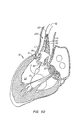
- FIG. 1-4 a first embodiment of replacement heart valve apparatus in accordance with the present invention is described, including a method of actively foreshortening and expanding the apparatus from a delivery configuration and to a deployed configuration.
- Apparatus 10 comprises replacement valve 20 disposed within and coupled to anchor 30.
- Figures 1 schematically illustrate individual cells of anchor 30 of apparatus 10, and should be viewed as if the cylindrical anchor has been cut open and laid flat.
- Figures 2 schematically illustrate a detail portion of apparatus 10 in side-section.
- Anchor 30 has a lip region 32, a skirt region 34 and a body region 36.
- First, second and third posts 38a, 38b and 38c, respectively, are coupled to skirt region 34 and extend within lumen 31 of anchor 30.
- Posts 38 preferably are spaced 120° apart from one another about the circumference of anchor 30.
- Anchor 30 preferably is fabricated by using self-expanding patterns (laser cut or chemically milled), braids, and materials, such as a stainless steel, nickel-titanium (“Nitinol”) or cobalt chromium but alternatively may be fabricated using balloon-expandable patterns where the anchor is designed to plastically deform to it's final shape by means of balloon expansion.
- Replacement valve 20 is preferably from biologic tissues, e.g.
- porcine valve leaflets or bovine or equine pericardium tissues alternatively it can be made from tissue engineered materials (such as extracellular matrix material from Small Intestinal Submucosa (SIS)) but alternatively may be prosthetic from an elastomeric polymer or silicone, Nitinol or stainless steel mesh or pattern (sputtered, chemically milled or laser cut).
- the leaflet may also be made of a composite of the elastomeric or silicone materials and metal alloys or other fibers such Kevlar or carbon.
- Annular base 22 of replacement valve 20 preferably is coupled to skirt region 34 of anchor 30, while commissures 24 of replacement valve leaflets 26 are coupled to posts 38.
- Anchor 30 may be actuated using external non-hydraulic or non-pneumatic force to actively foreshorten in order to increase its radial strength. As shown below, the proximal and distal end regions of anchor 30 may be actuated independently.
- the anchor and valve may be placed and expanded in order to visualize their location with respect to the native valve and other anatomical features and to visualize operation of the valve. The anchor and valve may thereafter be repositioned and even retrieved into the delivery sheath or catheter.
- the apparatus may be delivered to the vicinity of the patient's aortic valve in a retrograde approach in a catheter having a diameter no more than 23 french, preferably no more than 21 french, more preferably no more than 19 french, or more preferably no more than 17 french.
- the anchor and replacement valve capture the native valve leaflets and positively lock to maintain configuration and position.
- a deployment tool is used to actuate, reposition, lock and/or retrieve anchor 30.
- a non-hydraulic or non-pneumatic anchor actuator is used.
- the actuator is a deployment tool that includes distal region control actuators 50, control actuators 60 (embodied here as rods or tubes) and proximal region control actuators 62.
- Locks 40 include posts or arms 38 preferably with male interlocking elements 44 extending from skirt region 34 and mating female interlocking elements 42 in lip region 32. Male interlocking elements 44 have eyelets 45.
- Control actuators 50 pass from a delivery system for apparatus 10 through female interlocking elements 42, through eyelets 45 of male interlocking elements 44, and back through female interlocking elements 42, such that a double strand of wire 50 passes through each female interlocking element 42 for manipulation by a medical practitioner external to the patient to actuate and control the anchor by changing the anchor's shape.
- Control actuators 50 may comprise, for example, strands of suture or wire.
- Actuators 60 are reversibly coupled to apparatus 10 and may be used in conjunction with actuators 50 to actuate anchor 30, e.g., to foreshorten and lock apparatus 10 in the fully deployed configuration. Actuators 60 also facilitate repositioning and retrieval of apparatus 10, as described hereinafter.
- anchor 30 may be foreshortened and radially expanded by applying a distally directed force on actuators 60 while proximally retracting actuators 50.
- control actuators 62 pass through interior lumens 61 of actuators 60. This ensures that actuators 60 are aligned properly with apparatus 10 during deployment and foreshortening.
- Control actuators 62 can also actuate anchor 60; proximally directed forces on control actuators 62 contacts the proximal lip region 32 of anchor 30. Actuators 62 also act to couple and decouple actuators 60 from apparatus 10. Actuators 62 may comprise, for example, strands of suture or wire.
- Figures 1A and 2A illustrate anchor 30 in a delivery configuration or in a partially deployed configuration (e.g., after dynamic self-expansion expansion from a constrained delivery configuration within a delivery sheath).
- Anchor 30 has a relatively long length and a relatively small width in the delivery or partially deployed configuration, as compared to the foreshortened and fully deployed configuration of Figures IB and 2B.
- replacement valve 20 is collapsed within lumen 31 of anchor 30.
- Retraction of actuators 50 relative to actuators 60 foreshortens anchor 30, which increases the anchor's width while decreasing its length.
- Such foreshortening also properly seats replacement valve 20 within lumen 31 of anchor 30.
- Imposed foreshortening will enhance radial force applied by apparatus 10 to surrounding tissue over at least a portion of anchor 30.
- the anchor exerts an outward force on surrounding tissue to engage the tissue in such way to prevent migration of anchor caused by force of blood against closed leaflet during diastole.
- This anchoring force is preferably 1 to 2 lbs, more preferably 2 to 4 lbs, or more preferably 4 to 10 lbs.
- the anchoring force is preferably greater than 1 pound, more preferably greater than 2 pounds, or more preferably greater than 4 pounds.
- Enhanced radial force of the anchor is also important for enhanced crush resistance of the anchor against the surrounding tissue due to the healing response (fibrosis and contraction of annulus over a longer period of time) or to dynamic changes of pressure and flow at each heart beat
- the anchor pattern or braid is designed to have gaps or areas where the native tissue is allowed to protrude through the anchor slightly (not shown) and as the foreshortening is applied, the tissue is trapped in the anchor. This feature would provide additional means to prevent anchor migration and enhance long term stability of the device.
- Deployment of apparatus 10 is fully reversible until lock 40 has been locked via mating of male interlocking elements 44 with female interlocking elements 42. Deployment is then completed by decoupling actuators 60 from lip section 32 of anchor 30 by retracting one end of each actuator 62 relative to the other end of the actuator, and by retracting one end of each actuator 50 relative to the other end of the actuator until each actuator has been removed from eyelet 45 of its corresponding male interlocking element 44.
- body region 36 of anchor 30 optionally may comprise barb elements 37 that protrude from anchor 30 in the fully deployed configuration, for example, for engagement of a patient's native valve leaflets and to preclude migration of the apparatus.
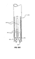
- a delivery and deployment system for a self-expanding embodiment of apparatus 10 including a sheath 110 having a lumen 112.
- Self-expanding anchor 30 is collapsible to a delivery configuration within lumen 112 of sheath 110, such that apparatus 10 may be delivered via delivery system 100.
- apparatus 10 may be deployed from lumen 112 by retracting sheath 110 relative to apparatus 10, control actuators 50 and actuators 60, which causes anchor 30 to dynamically self-expand to a partially deployed configuration.
- Control actuators 50 then are retracted relative to apparatus 10 and actuators 60 to impose foreshortening upon anchor 30, as seen in Figure 3B .
- actuators 60 push against lip region 32 of anchor 30, while actuators 50 pull on posts 38 of the anchor.
- Actuators 62 may be retracted along with actuators 50 to enhance the distally-directed pushing force applied by actuators 60 to lip region 32.
- Apparatus 10 comprises enhanced radial strength in the fully deployed configuration as compared to the partially deployed configuration of Figure 3A .
- Deployment of apparatus 10 is fully reversible until locks 40 have been actuated. For example, just prior to locking the position of the anchor and valve and the operation of the valve may be observed under fluoroscopy. If the position needs to be changed, by alternately relaxing and reapplying the proximally directed forces exerted by control actuators 50 and/or control actuators 62 and the distally directed forces exerted by actuators 60, expansion and contraction of the lip and skirt regions of anchor 30 may be independently controlled so that the anchor and valve can be moved to, e.g., avoid blocking the coronary ostia or impinging on the mitral valve.
- Apparatus 10 may also be completely retrieved within lumen 112 of sheath 110 by simultaneously proximally retracting actuators 50 and actuators 60/actuators 62 relative to sheath 110. Apparatus 10 then may be removed from the patient or repositioned for subsequent redeployment.
- FIG. 4A sheath 110 is retracted relative to apparatus 10, actuators 50 and actuators 60, thereby causing self-expandable anchor 30 to dynamically self-expand apparatus 10 from the collapsed delivery configuration within lumen 112 of sheath 110 to the partially deployed configuration.
- Apparatus 10 may then be dynamically repositioned via actuators 60 to properly orient the apparatus, e.g. relative to a patient's native valve leaflets.
- control actuators 50 are retracted while actuators 60 are advanced, thereby urging lip region 32 of anchor 30 in a distal direction while urging posts 38 of the anchor in a proximal direction.
- sheath 110 of delivery system 100 is percutaneously advanced over guide wire G, preferably in a retrograde fashion (although an antegrade or hybrid approach alternatively may be used), through a patient's aorta A to the patient's diseased aortic valve AV.
- a nosecone 102 precedes sheath 110 in a known manner.
- sheath 110 is positioned such that its distal region is disposed within left ventricle LV of the patient's heart H.
- Apparatus 10 is deployed from lumen 112 of sheath 110, for example, under fluoroscopic guidance, such that anchor 30 of apparatus 10 dynamically self-expands to a partially deployed configuration, as in Figure 5C .
- apparatus 10 may be retracted within lumen 112 of sheath 110 via actuators 50 - even after anchor 30 has dynamically expanded to the partially deployed configuration, for example, to abort the procedure or to reposition apparatus 10 or delivery system 100.
- apparatus 10 may be dynamically repositioned, e.g. via sheath 110 and/or actuators 60, in order to properly align the apparatus relative to anatomical landmarks, such as the patient's coronary ostia or the patient's native valve leaflets L.
- skirt region 34 of anchor 30 preferably is disposed distal of the leaflets, while body region 36 is disposed across the leaflets and lip region 32 is disposed proximal of the leaflets.
- actuators 50 are retracted relative to actuators 60 to impose foreshortening upon anchor 30 and expand apparatus 10 to the fully deployed configuration, as in Figure 5D .
- Foreshortening increases the radial strength of anchor 30 to ensure prolonged patency of valve annulus An, as well as to provide a better seal for apparatus 10 that reduces paravalvular regurgitation.
- locks 40 maintain imposed foreshortening.
- Replacement valve 20 is properly seated within anchor 30, and normal blood flow between left ventricle LV and aorta A is thereafter regulated by apparatus 10. Deployment of apparatus 10 advantageously is fully reversible until locks 40 have been actuated.
- actuators 50 have been pulled from eyelets 45 of male elements 44 of locks 40, actuators 60 are decoupled from anchor 30, e.g. via actuators 62, and delivery system 100 is removed from the patient, thereby completing deployment of apparatus 10.
- Optional barb elements 37 engage the patient's native valve leaflets, e.g. to further preclude migration of the apparatus and/or reduce paravalvular regurgitation.
- Figures 5G and 5H show further details of deployment using a deployment apparatus.
- Apparatus 10 is deployed from lumen Lu of sheath 110, for example, under fluoroscopic guidance by proximally retracting proximal handle 111 of sheath 110 relative to shaft 108, such that anchor 30 of apparatus 10 dynamically self-expands to the partially deployed configuration of Figure 5C .
- apparatus 10 may be retracted within lumen Lu of sheath 110 by retracting shaft 108 relative to the sheath, and thereby retracting actuators 106a coupled to anchor 30 relative to sheath 110. In this manner, anchor 30 may be retrieved even after the anchor has dynamically expanded to the partially deployed configuration, for example, to abort the procedure or to reposition apparatus 10 or delivery system 100.
- apparatus 10 may be dynamically repositioned, in order to properly align the apparatus relative to anatomical landmarks, such as the patient's coronary ostia or the patient's native valve leaflets L.
- a distal region of anchor 30 preferably is disposed distal of the leaflets, while a central region of the anchor is disposed across the leaflets and a proximal region is disposed proximal of the leaflets.
- actuators 106b are proximally retracted relative to actuators 106a, e.g., via knob 126 of handle 120, to impose foreshortening upon anchor 30 and further expand apparatus 10 to the fully deployed configuration, as in Figure 5D .
- Foreshortening increases the radial strength of anchor 30 to ensure prolonged patency of valve annulus An, as well as to provide a better seal for apparatus 10 that reduces paravalvular regurgitation.
- Lock 40 formed by engaging post lock elements 44 of posts 32 with anchor lock elements 34 of anchor 30 maintains imposed foreshortening.
- Replacement valve 20 is properly seated within anchor 30, and normal blood flow between left ventricle LV and aorta A is thereafter completely regulated by apparatus 10, although valve 20 is functional during deployment as well.
- Deployment of apparatus 10 advantageously is fully reversible until the locks have been actuated.
- Releasable lock prevention mechanisms may be provided to ensure that the locks are not actuated prematurely.
- the locks may be reversible, such that apparatus 10 may be retrieved or repositioned even after actuation of the locks.
- actuators 106a are decoupled from anchor 30 by actuating releasable attachment mechanisms, e.g., by retracting release actuators 112 relative to the actuators 106a via knob 122 of handle 120.
- actuators 106b are decoupled from posts 32 by actuating releasable attachment mechanisms, e.g., by retracting release actuators 112 relative to the actuators 106b via knob 124 of handle 120.
- delivery system 100 then may be removed from the patient, thereby completing deployment of apparatus 10.
- Optional barb elements 37 engage the patient's native valve leaflets, e.g. to preclude migration of the apparatus and/or to reduce paravalvular regurgitation.
- modified delivery system 100' delivers apparatus 10 to diseased aortic valve AV within sheath 110.
- apparatus 10 is deployed from lumen 112 of sheath 110, for example, under fluoroscopic guidance, such that anchor 30 of apparatus 10 dynamically self-expands to a partially deployed configuration.
- deployment of apparatus 10 via delivery system 100' is fully reversible until locks 40 have been actuated.
- Delivery system 100' comprises leaflet engagement element 120, which preferably self-expands along with anchor 30.
- Engagement element 120 is disposed between actuators 60 of delivery system 100' and lip region 32 of anchor 30.
- Element 120 releasably engages the anchor.
- the element is initially deployed proximal of the patient's native valve leaflets L.
- Apparatus 10 arid element 120 then may be advanced/dynamically repositioned until engagement element positively registers against the leaflets, thereby ensuring proper positioning of apparatus 10.
- delivery system 100' includes filter structure 61 A (e.g., filter membrane or braid) as part of push actuators 60 to act as an embolic protection element.
- filter structure 61 A e.g., filter membrane or braid
- Emboli can be generated during manipulation and placement of anchor from either diseased native leaflet or surrounding aortic tissue and can cause blockage.
- Arrows 6 IB in Figure 6E show blood flow through filter structure 61 A where blood is allowed to flow but emboli is trapped in the delivery system and removed with it at the end of the procedure.
- foreshortening may be imposed upon anchor 30 while element 120 is disposed proximal of the leaflets, as in Figure 6D .
- element 120 Upon positive registration of element 120 against leaflets L, element 120 precludes further distal migration of apparatus 10 during additional foreshortening, thereby reducing a risk of improperly positioning the apparatus.
- Figure 6E details engagement of element 120 against the native leaflets.
- element 120, actuators 50 and actuators 60 are decoupled from the apparatus, and delivery system 100' is removed from the patient, thereby completing the procedure.
- leaflet engagement element 120 is coupled to anchor 30 of apparatus 10', rather than to delivery system 100.
- Engagement element 120 remains implanted in the patient post-deployment of apparatus 10'.
- Leaflets L are sandwiched between lip region 32 of anchor 30 and element 120 in the fully deployed configuration. In this manner, element 120 positively registers apparatus 10' relative to the leaflets and precludes distal migration of the apparatus over time.
- apparatus 10 comprises anchor 30' that maybe fabricated from balloon-expandable materials.
- Delivery system 100 comprises inflatable member 130 disposed in a deflated configuration within lumen 31 of anchor 30' .
- optional outer sheath 110 is retracted, and inflatable member 130 is inflated to expand anchor 30' to the fully deployed configuration.
- actuators 50 and 62 and actuators 60 maybe used to assist deployment of anchor 30' and actuation of locks 40, as well as to provide reversibility and retrievability of apparatus 10" prior to actuation of locks 40.
- actuators 50 and 62 and actuators 60 are removed from apparatus 10", and delivery system 100" is removed, as seen in Figure 8C .
- anchor 30' may be partially deployed via partial expansion of inflatable member 130.
- the inflatable member would then be advanced within replacement valve 20 prior to inflation of inflatable member 130 and full deployment of apparatus 10".
- Inflation pressures used will range from about 3 to 6 arm, or more preferably from about 4 to 5 arm, though higher and lower atm pressures may also be used (e.g., greater than 3 atm, more preferably greater than 4 atm, more preferably greater than 5 atm, or more preferably greater than 6 atm).
- separation of inflatable member 130 from replacement valve 20, until partial deployment of apparatus 10" at a treatment site is expected to reduce a delivery profile of the apparatus, as compared to previously known apparatus. This profile reduction may facilitate retrograde delivery and deployment of apparatus 10", even when anchor 30' is balloon-expandable.
- anchor 30' has illustratively been described as fabricated from balloon-expandable materials, it should be understood that anchor 30' alternatively may be fabricated from self-expanding materials whose expansion optionally may be balloon-assisted. In such a configuration, anchor 30' would expand to a partially deployed configuration upon removal of outer sheath 110. If required, inflatable member 130 then would be advanced within replacement valve 20 prior to inflation. Inflatable member 130 would assist full deployment of apparatus 10", for example, when the radial force required to overcome resistance from impinging tissue were too great to be overcome simply by manipulation of actuators 50 and actuators 60.
- inflatable member 130 within replacement valve 20 is expected to reduce a delivery profile of the apparatus, as compared to previously known apparatus. This reduction may facilitate retrograde delivery and deployment of apparatus 10".
- Figures 9 and 10 illustratively show apparatus 10' of Figures 7 used in combination with delivery system 100" of Figures 8 .
- Figure 10 illustrates a sectional view of delivery system 100".
- Inner shaft 132 of inflatable member 130 preferably is about 4 Fr in diameter, and comprises lumen 133 configured for passage of guidewire G, having a diameter of about 0.035", therethrough.
- Push actuators 60 and pull actuators 50 pass through guidetube 140, which preferably has a diameter of about 15 Fr or smaller.
- Guide tube 140 is disposed within lumen 112 of outer sheath 110, which preferably has a diameter of about 17 Fr or smaller.
- apparatus 10' is delivered to diseased aortic valve AV within lumen 112 of sheath 110.
- sheath 110 is retracted relative to apparatus 10' to dynamically self-expand the apparatus to the partially deployed configuration.
- nosecone 102 which is attached to a pre-slit lumen (not shown) that facilitates its removal prior to loading and advancing of a regular angioplasty balloon catheter over guidewire and inside delivery system 110.
- pull actuators 50 and push actuators 60 are manipulated from external to the patient to foreshorten anchor 30 and sufficiently expand lumen 31 of the anchor to facilitate advancement of inflatable member 130 within replacement valve 20. Also shown is the tip of an angioplasty catheter 130 being advanced through delivery system 110.
- the angioplasty balloon catheter or inflatable member 130 then is advanced within the replacement valve, as in Figure 9D , and additional foreshortening is imposed upon anchor 30 to actuate locks 40, as in Figure 9E .
- the inflatable member is inflated to further displace the patient's native valve leaflets L and ensure adequate blood flow through, and long-term patency of, replacement valve 20, as in Figure 9F .
- Inflatable member 130 then is deflated and removed from the patient, as in Figure 9G .
- Push actuators 60 optionally may be used to further set leaflet engagement element 120, or optional barbs B along posts 38, more deeply within leaflets L, as in Figure 9H . Then, delivery system 100" is removed from the patient, thereby completing percutaneous heart valve replacement.
- lock 40' comprises male interlocking element 44 as described previously.
- female interlocking element 42' illustratively comprises a triangular shape, as compared to the round shape of interlocking element 42 described previously.
- the triangular shape of female interlocking element 42' may facilitate mating of male interlocking element 44 with the female interlocking element without necessitating deformation of the male interlocking element.
- lock 40" comprises alternative male interlocking element 44' having multiple in-line arrowheads 46 along posts 38. Each arrowhead comprises resiliently deformable appendages 48 to facilitate passage through female interlocking element 42. Appendages 48 optionally comprise eyelets 49, such that control actuator 50 or a secondary wire may pass therethrough to constrain the appendages in the deformed configuration.
- one or more arrowheads 46 of male interlocking element 44' are drawn through female interlocking element 42, and the wire is removed from eyelets 49, thereby causing appendages 48 to resiliently expand and actuate lock 40".
- providing multiple arrowheads 46 along posts 38 yields a ratchet that facilitates in-vivo determination of a degree of foreshortening imposed upon apparatus of the present invention.
- optionally constraining appendages 48 of arrowheads 46 via eyelets 49 prevents actuation of lock 40" (and thus deployment of apparatus of the present invention) even after male element 44' has been advanced through female element 42. Only after a medical practitioner has removed the wire constraining appendages 48 is lock 40'' fully engaged and deployment no longer reversible.
- Lock 40'" of Figure 11C is similar to lock 40" of Figure 11B , except that optional eyelets 49 on appendages 48 have been replaced by optional overtube 47.
- Overtube 47 serves a similar function to eyelets 49 by constraining appendages 48 to prevent locking until a medical practitioner has determined that apparatus of the present invention has been foreshortened and positioned adequately at a treatment site. Overtube 47 is then removed, which causes the appendages to resiliently expand, thereby fully actuating lock 40"'.
- FIG. 12 an alternative locking mechanism is described that is configured to engage the patient's aorta.
- Male interlocking elements 44" of locks 40"" comprise arrowheads 46' having sharpened appendages 48'.
- apparatus 10 Upon expansion from the delivery configuration of Figure 12A to the foreshortened configuration of Figure 12B , apparatus 10 positions sharpened appendages 48' adjacent the patient's aorta A. Appendages 48' engage the aortic wall and reduce a risk of device migration over time.
- apparatus 10 has been implanted at the site of diseased aortic valve AV, for example, using techniques described hereinabove.
- the surface of native valve leaflets L is irregular, and interface I between leaflets L and anchor 30 may comprise gaps where blood B may seep through.
- Such leakage poses a risk of blood clot formation or insufficient blood flow.
- Compliant sacs 200 may be disposed about the exterior of anchor 30 to provide a more efficient seal along irregular interface I. Sacs 200 may be filled with an appropriate material, for example, water, blood, foam or a hydrogel. Alternative fill materials will be apparent.
- sacs 200 are provided as discrete sacs at different positions along the height of anchor 30.
- the sacs are provided as continuous cylinders at various heights.
- a single sac is provided with a cylindrical shape that spans multiple heights.
- the sacs of Figure 15D are discrete, smaller and provided in larger quantities.
- Figure 15E provides a spiral sac. Alternative sac configurations will be apparent to those of skill in the art.
- sacs 20 comprise 'fish-scale' slots 202 that may be back-filled, for example, with ambient blood passing through replacement valve 20.
- the sacs comprise pores 204 that may be used to fill the sacs.
- the sacs open to lumen 31 of anchor 30 and are filled by blood washing past the sacs as the blood moves through apparatus 10.
- FIGs 17 and 18 show yet another alternative embodiment of the anchor lock.
- Anchor 300 has a plurality of male interlocking elements 302 having eyelets 304 formed therein.
- Male interlocking elements are connected to braided structure 300 by inter-weaving elements 302 (and 308) or alternatively suturing, soldering, welding, or connecting with adhesive.
- Valve commissures 24 are connected to male interlocking elements 302 along their length.
- Replacement valve 20 annular base 22 is connected to the distal end 34 of anchor 300 (or 30) as is illustrated in figures 1A and IB.
- Male interlocking elements 302 also include holes 306 that mate with tabs 310 extending into holes 312 in female interlocking elements 308.
- control actuators 314 passing through eyelets 304 and holes 312 are pulled proximally with respect to the proximal end of braided anchor 300 to draw the male interlocking elements through holes 312 so that tabs 310 engage holes 306 in male interlocking elements 302.
- release actuators 314B that passes through eylet 304B in female interlocking element 308. If needed, during the procedure, the user may pull on release actuators 314B reversing orientation of tabs 310 releasing the anchor and allowing for repositioning of the device or it's removal from the patient. After the desired final position has been attained, release actuator 314B and control actuator 314 be removed from the patient with the delivery system.
- Control actuators 62 extend through actuators 60 from outside the patient, loop through the proximal region of anchor 30 and extend partially back into tube 60 (i.e., an anchor actuator).
- the doubled up portion of control actuator 62 creates a force fit within tube 60 that maintains the control actuators's position with respect to tube 60 when all confrol actuators 62 are pulled proximally to place a proximally directed force on anchor 30.
- control actuator 62 When a single half of control actuator 62 is pulled proximally, however, the frictional fit between that control wire and the tube in which it is disposed is overcome, enabling the end 63 of control actuator 62 to pull free of the tube, as shown in Figure 21 , thereby releasing anchor 30.
- Anchor 350 is made of a metal braid, such as Nitinol or stainless steel.
- a replacement valve 354 is disposed within anchor 350.
- Anchor 350 is actuated in substantially the same way as anchor 30 of Figures 1-4 through the application of proximally and distally directed forces from confrol actuators (not shown) and actuators 352.
- Figures 25 and 26 show yet another embodiment of the delivery and deployment apparatus of the invention.
- the nosecone e.g., element 102 of Figures 5
- an angioplasty balloon catheter 360 e.g., an angioplasty balloon catheter 360.
- expandable balloon cathether 360 precedes sheath 110 on guidewire G.
- anchor 30 and valve 20 are expanded through the operation of actuators 60 and the control actuators (not shown) as described above, balloon cathether 360 is retracted proximally within the expanded anchor and valve and expanded further as described above with respect to Figures 8 .
- Figures 27-31 show seals 370 that expand over time to seal the interface between the anchor and valve and the patient's tissue.
- Seals 370 are preferably formed from Nitinol wire surrounded by an expandable foam.
- the foam 372 is compressed about the wire 374 and held in the compressed form by a time-released coating 376. After deployment, coating 376 dissolves in vivo to allow foam 372 to expand, as shown in Figures 30 and 31 .
- Figures 32-34 show another way to seal the replacement valve against leakage.
- a fabric seal 380 extends from the distal end of valve 20 and back proximally over anchor 30 during delivery. When deployed, as shown in Figures 33 and 34 , fabric seal 380 bunches up to create fabric flaps and pockets that extend into spaces formed by the native valve leaflets 382, particularly when the pockets are filled with blood in response to backflow blood pressure. This arrangement creates a seal around the replacement valve.
- FIGS 35A-H show another embodiment of a replacement heart valve apparatus in accordance with the present invention.
- Apparatus 450 comprises replacement valve 460 (see Figures 37B and 38C ) disposed within and coupled to anchor 470.
- Replacement valve 460 is preferably biologic, e.g. porcine, but alternatively may be synthetic.
- Anchor 470 preferably is fabricated from self-expanding materials, such as a stainless steel wire mesh or a nickel-titanium alloy (“Nitinol”), and comprises lip region 472, skirt region 474, and body regions 476a, 476b and 476c.
- Replacement valve 460 preferably is coupled to skirt region 474, but alternatively may be coupled to other regions of the anchor.
- lip region 472 and skirt region 474 are configured to expand and engage/capture a patient's native valve leaflets, thereby providing positive registration, reducing paravalvular regurgitation, reducing device migration, etc.
- apparatus 450 is collapsible to a delivery configuration, wherein the apparatus may be delivered via delivery system 410.
- Delivery system 410 comprises sheath 420 having lumen 422, as well as actuators 424a and 424b seen in Figures 35D-35G .
- Actuators 424a are configured to expand skirt region 474 of anchor 470, as well as replacement valve 460 coupled thereto, while actuators 424b are configured to expand lip region 472.
- apparatus 450 may be delivered and deployed from lumen 422 of catheter 420 while the apparatus is disposed in the collapsed delivery configuration.
- catheter 420 is retracted relative to apparatus 450, which causes anchor 470 to dynamically self-expand to a partially deployed configuration.
- Actuators 424a are then retracted to expand skirt region 474, as seen in Figures 35E and 35F .
- such expansion may be maintained via locking features described hereinafter.
- actuators 424b are retracted to expand lip region 472 and fully deploy apparatus 450.
- expansion of lip region 472 preferably may be maintained via locking features.
- actuators 424 may be removed from apparatus 450, thereby separating delivery system 410 from the apparatus. Delivery system 410 then may be removed, as seen in Figure 35H .
- lip region 472 optionally may be expanded prior to expansion of skirt region 474.
- lip region 472 and skirt region 474 optionally may be expanded simultaneously, in parallel, in a step-wise fashion or sequentially.
- delivery of apparatus 450 is fully reversible until lip region 472 or skirt region 474 has been locked in the expanded configuration.
- FIG. 36A-E individual cells of anchor 470 of apparatus 450 are described to detail deployment and expansion of the apparatus.
- individual cells of lip region 472, skirt region 474 and body regions 476a, 476b and 476c are shown in the collapsed delivery configuration, as they would appear while disposed within lumen 422 of sheath 420 of delivery system 410 of Figures 35 .
- a portion of the cells forming body regions 476 for example, every 'nth' row of cells, comprises locking features.
- Body region 476a comprises male interlocking element 482 of lip lock 480, while body region 476b comprises female interlocking element 484 of lip lock 480.
- Male element 482 comprises eyelet 483.
- Wire 424b passes from female interlocking element 484 through eyelet 483 and back through female interlocking element 484, such that there is a double strand of wire 424b that passes through lumen 422 of catheter 420 for manipulation by a medical practitioner external to the patient.
- Body region 476b further comprises male interlocking element 492 of skirt lock 490, while body region 476c comprises female interlocking element 494 of the skirt lock.
- Wire 424a passes from female interlocking element 494 through eyelet 493 of male interlocking element 492, and back through female interlocking element 494.
- Lip lock 480 is configured to maintain expansion of lip region 472, while skirt lock 490 is configured to maintain expansion of skirt region 474.
- anchor 470 is shown in the partially deployed configuration, e.g., after deployment from lumen 422 of sheath 420.
- Full deployment is then achieved by refracting actuators 424 relative to anchor 470, and expanding lip region 472 and skirt region 474 outward, as seen in Figures 36C and 36D .
- expansion continues until the male elements engage the female interlocking elements of lip lock 480 and skirt lock 490, thereby maintaining such expansion (lip lock 480 shown in Figure 36E ).
- deployment of apparatus 450 is fully reversible until lip lock 480 and/or skirt lock 490 has been actuated.
- FIG. 37A-B isometric views, partially in section, further illustrate apparatus 450 in the fully deployed and expanded configuration.
- Figure 37A illustrates the wireframe structure of anchor 470
- Figure 37B illustrates an embodiment of anchor 470 covered in a biocompatible material B. Placement of replacement valve 460 within apparatus 450 may be seen in Figure 37B .
- the patient's native valve is captured between lip region 472 and skirt region 474 of anchor 470 in the fully deployed configuration (see Figure 38B ).
- Delivery system 410 having apparatus 450 disposed therein, is percutaneously advanced, preferably in a retrograde fashion, through a patient's aorta A to the patient's diseased aortic valve AV.
- Sheath 420 is positioned such that its distal end is disposed within left ventricle LV of the patient's heart H.
- apparatus 450 is deployed from lumen 422 of sheath 420, for example, under fluoroscopic guidance, such that skirt section 474 is disposed within left ventricle LV, body section 476b is disposed across the patient's native valve leaflets L, and lip section 472 is disposed within the patient's aorta A.
- apparatus 450 may be dynamically repositioned to obtain proper alignment with the anatomical landmarks.
- apparatus 450 may be refracted within lumen 422 of sheath 420 via actuators 424, even after anchor 470 has dynamically expanded to the partially deployed configuration, for example, to abort the procedure or to reposition sheath 420.
- skirt region 474 of anchor 470 is locked in the expanded configuration via skirt lock 490, as previously described with respect to Figures 36 .
- skirt region 474 is maneuvered such that it engages the patient's valve annulus An and/or native valve leaflets L, thereby providing positive registration of apparatus 450 relative to the anatomical landmarks.
- Elements 424b are then actuated external to the patient in order to expand lip region 472, as previously described in Figures 35 .
- Lip region 472 is locked in the expanded configuration via lip lock 480.
- deployment of apparatus 450 is fully reversible until lip lock 480 and/or skirt lock 490 has been actuated.
- Elements 424 are pulled from eyelets 483 and 493, and delivery system 410 is removed from the patient. As will be apparent, the order of expansion of lip region 472 and skirt region 474 may be reversed, concurrent, etc.
- lip region 472 engages the patient's native valve leaflets L, thereby providing additional positive registration and reducing a risk of lip region 472 blocking the patient's coronary ostia O.
- Figure 38C illustrates the same in cross-sectional view, while also showing the position of replacement valve 460.
- the patient's native leaflets are engaged and/or captured between lip region 472 and skirt region 474.
- lip region 472 precludes distal migration of apparatus 450, while skirt region 474 precludes proximal migration. It is expected that lip region 472 and skirt region 474 also will reduce paravalvular regurgitation.
- apparatus 510 comprises a two-piece device having custom-designed expandable anchor piece 550 of Figures 39 and expandable replacement valve piece 600 of Figures 40 .
- Both anchor piece 550 and valve piece 600 have reduced delivery configurations and expanded deployed configurations. Both may be either balloon expandable (e.g. fabricated from a stainless steel) or self-expanding (e.g. fabricated from a nickel-titanium alloy (“Nitinol”) or from a wire mesh) from the delivery to the deployed configurations.
- apparatus 510 When replacing a patient's aortic valve, apparatus 510 preferably may be delivered through the patient's aorta without requiring a transseptal approach, thereby reducing patient trauma, complications and recovery time. Furthermore, apparatus 510 enables dynamic repositioning of anchor piece 550 during delivery and facilitates positive registration of apparatus 510 relative to the native position of the patient's valve, thereby reducing a risk of device migration and reducing a risk of blocking or impeding flow to the patient's coronary ostia. Furthermore, the expanded deployed configuration of apparatus 510, as seen in Figure 41D , is adapted to reduce paravalvular regurgitation, as well as to facilitate proper seating of valve piece 600 within anchor piece 550.
- anchor piece 550 preferably comprises three sections.
- Lip section 560 is adapted to engage the patient's native valve leaflets to provide positive registration and ensure accurate placement of the anchor relative to the patient's valve annulus during deployment, while allowing for dynamic repositioning of the anchor during deployment. Lip section 560 also maintains proper positioning of composite anchor/valve apparatus 510 post-deployment to preclude distal migration.
- Lip section 560 optionally may be covered or coated with biocompatible film B (see Figures 41 ) to ensure engagement of the native valve leaflets. It is expected that covering lip section 560 with film B especially would be indicated when the native leaflets are stenosed and/or fused together
- Groove section 570 of anchor piece 550 is adapted to engage an expandable frame portion, described hereinbelow, of valve piece 600 to couple anchor piece 550 to valve piece 600.
- groove section 570 comprises additional material and reduced openings or gaps G, which is expected to reduce tissue protrusion through the gaps upon deployment, thereby facilitating proper seating of the valve within the anchor.
- Groove section 570 optionally may be covered or coated with biocompatible film B (see Figures 41 ) to further reduce native valve tissue protrusion through gaps G.
- skirt section 580 of anchor piece 550 maintains proper positioning of composite anchor/valve apparatus 510 post-deployment by precluding proximal migration.
- skirt section 580 When replacing a patient's aortic valve, skirt section 580 is deployed within the patient's left ventricle.
- skirt section 580 optionally may be covered or coated with biocompatible film B (see Figures 41 ) to reduce paravalvular regurgitation.
- all, a portion of, or none of anchor piece 50 may be covered or coated with biocompatible film B.
- anchor piece 550 has been flattened out to illustrate the basic anchor cell structure, as well as to illustrate techniques for manufacturing anchor piece 550.
- anchor 550 in order to form the entire anchor, anchor 550 would be bent at the locations indicated in Figure 39A , and the basic anchor cell structure would be revolved to form a joined 360° structure.
- Lip section 560 would be bent back into the page to form a lip that doubles over the groove section, groove section 570 would be bent out of the page into a'C- or 'U'-shaped groove, while skirt section 580 would be bent back into the page.
- Figure 39B shows the anchor portion after bending and in an expanded deployed configuration.
- the basic anchor cell structure seen in Figure 39A is preferably formed through laser cutting of a flat sheet or of a hollow tube placed on a mandrel. When formed from a flat sheet, the sheet would be cut to the required number of anchor cells, bent to the proper shape, and revolved to form a cylinder. The ends of the cylinder would then be joined together, for example, by welding.
- anchor piece 550 would be formed from an appropriate material, such as stainless steel, and then crimped onto a balloon delivery catheter in a collapsed delivery configuration. If self-expanding and formed from a shape-memory material, such as a nickel-titanium alloy (“Nitinol”), the anchor piece would be heat-set such that it could be constrained within a sheath in the collapsed delivery configuration, and then would dynamically self-expand to the expanded deployed configuration upon removal of the sheath. Likewise, if anchor piece 550 were formed from a wire mesh or braid, such as a spring steel braid, the anchor would be constrained within a sheath in the delivery configuration and dynamically expanded to the deployed configuration upon removal of the sheath.
- a shape-memory material such as a nickel-titanium alloy (“Nitinol)
- valve piece 600 is described in greater detail.
- Figure 40A illustrates valve piece 600 in a collapsed delivery configuration
- Figure 40B illustrates the valve piece in an expanded deployed configuration.
- Valve piece 600 comprises replacement valve 610 coupled to expandable frame 620.
- Replacement valve 610 is preferably biologic, although synthetic valves may also be used.
- Replacement valve 610 preferably comprises three leaflets 611 coupled to three posts 621 of expandable frame 620.
- Expandable frame 620 is preferably formed from a continuous piece of material and may comprise tips 622 in the collapsed delivery configuration, which expand to form hoop 624 in the deployed configuration.
- Hoop 624 is adapted to engage groove section 570 of anchor piece 550 for coupling anchor piece 550 to valve piece 600.
- valve piece 600 may be balloon expandable and coupled to a balloon delivery catheter in the delivery configuration.
- anchor piece 550 may be self-expanding, e.g. Nitinol or wire mesh, and constrained within a sheath in the delivery configuration.
- valve piece 600 is advanced within anchor piece 550 in an at least partially compressed delivery configuration.
- tips 622 of frame 620 are expanded such that they engage groove section 570 of anchor piece 550.
- frame 620 continues to expand and form hoop 624. Hoop 624 flares out from the remainder of valve piece 600 and acts to properly locate the hoop within groove section 570.
- Figure 41D shows valve piece 600 in a fully deployed configuration, properly seated and friction locked within groove section 570 to form composite anchor/valve apparatus 510.
- Anchor piece 550 and valve piece 600 of apparatus 510 preferably are spaced apart and releasably coupled to a single delivery catheter while disposed in their reduced delivery configurations. Spacing the anchor and valve apart reduces a delivery profile of the device, thereby enabling delivery through a patient's aorta without requiring a transseptal approach.
- Delivery system 700 is adapted for use with a preferred self-expanding embodiment of apparatus 510.
- Delivery system 700 comprises delivery catheter 710 having inner tube 720, middle distal tube 730, and outer tube 740.
- Inner tube 720 comprises lumen 722 adapted for advancement over a standard guide wire, per se known.
- Middle distal tube 730 is coaxially disposed about a distal region of inner tube 720 and is coupled to a distal end 724 of the inner tube, thereby forming proximally-oriented annular bore 732 between inner tube 720 and middle tube 730 at a distal region of delivery catheter 710.
- Outer tube 740 is coaxially disposed about inner tube 720 and extends from a proximal region of the inner tube to a position at least partially coaxially overlapping middle distal tube 730.
- Outer tube 740 preferably comprises distal step 742, wherein lumen 743 of outer tube 740 is of increased diameter.
- Distal step 742 may overlap middle distal tube 730 and may also facilitate deployment of valve piece 600, as described hereinbelow with respect to Figures 45 .
- Proximally-oriented annular bore 732 between inner tube 720 and middle distal tube 730 is adapted to receive skirt section 580 and groove section 570 of anchor piece 550 in the reduced delivery configuration.
- Annular space 744 formed at the overlap between middle distal tube 730 and outer tube 740 is adapted to receive lip section 560 of anchor piece 550 in the reduced delivery configuration.
- More proximal annular space 746 between inner tube 720 and outer tube 740 may be adapted to receive replacement valve 610 and expandable frame 620 of valve piece 600 in the reduced delivery configuration.
- Inner tube 720 optionally may comprise retainer elements 726a and 726b to reduce migration of valve piece 600.
- Retainer elements 726 preferably are fabricated from a radiopaque material, such as platinum-iridium or gold, to facilitate deployment of valve piece 600, as well as coupling of the valve piece to anchor piece 550. Additional or alternative radiopaque elements may be disposed at other locations about delivery system 700 or apparatus 510, for example, in the vicinity of anchor piece 550.
- Delivery system 750 comprises two distinct catheters adapted to deliver the anchor and valve pieces, respectively: anchor delivery catheter 710' and valve delivery catheter 760.
- catheters 710' and 760 may be advanced sequentially to a patient's diseased heart valve for sequential deployment and coupling of anchor piece 550 to valve piece 600 to form composite two-piece apparatus 510.
- Delivery catheter 710' is substantially equivalent to catheter 710 described hereinabove, except that catheter 710' does not comprise retainer elements 726, and annular space 746 does not receive valve piece 600. Rather, valve piece 600 is received within catheter 760 in the collapsed delivery configuration.
- Catheter 760 comprises inner tube 770 and outer tube 780.
- Inner tube 770 comprises lumen 772 for advancement of catheter 760 over a guide wire.
- the inner tube optionally may also comprise retainer elements 774a and 774b, e.g. radiopaque retainer elements 774, to reduce migration of valve piece 600.
- Outer tube 780 is coaxially disposed about inner tuber 770 and preferably comprises distal step 782 to facilitate deployment and coupling of valve piece 600 to anchor piece 550, as described hereinbelow.
- Valve piece 600 may be received in annular space 776 between inner tube 770 and outer tube 780, and more preferably may be received within annular space 776 between retainer elements 774.
- either anchor piece 550 or valve piece 600 may be balloon expandable from the delivery configuration to the deployed configuration.
- Delivery system 800 is adapted for delivery of an embodiment of apparatus 510 wherein the valve piece is balloon expandable. Additional delivery systems - both single and multi-catheter - for deployment of alternative combinations of balloon and self-expandable elements of apparatus of the present invention will be apparent to those of skill in the art in view of the illustrative delivery systems provided in Figures 42-44 .
- delivery system 800 comprises delivery catheter 710".
- Delivery catheter 710 is substantially equivalent to delivery catheter 710 of delivery system 700, except that catheter 710" does not comprise retainer elements 726, and annular space 746 does not receive the valve piece.
- catheter 710" comprises inflatable balloon 802 coupled to the exterior of outer tube 740", as well as an inflation lumen (not shown) for reversibly delivering an inflation medium from a proximal region of catheter 710" into the interior of inflatable balloon 802 for expanding the balloon from a delivery configuration to a deployed configuration.
- Valve piece 600 may be crimped to the exterior of balloon 802 in the delivery configuration, then deployed and coupled to anchor piece 550 in vivo.
- Delivery catheter 710" preferably comprises radiopaque marker bands 804a and 804b disposed on either side of balloon 802 to facilitate proper positioning of valve piece 600 during deployment of the valve piece, for example, under fluoroscopic guidance.
- FIG. 45A a distal region of delivery system 700 of Figure 42 has been delivered through a patient's aorta A, e.g., over a guide wire and under fluoroscopic guidance using well-known percutaneous techniques, to a vicinity of diseased aortic valve AV of heart H.
- Apparatus 510 of Figures 39-41 is disposed in the collapsed delivery configuration within delivery catheter 710 with groove section 570 and skirt section 580 of anchor piece 550 collapsed within annular bore 732, and lip section 560 of anchor piece 550 collapsed within annular space 744.
- Valve piece 600 is disposed in the collapsed delivery configuration between retainer elements 726 within more proximal annular space 746. Separation of anchor piece 550 and valve piece 600 of apparatus 510 along the longitudinal axis of delivery catheter 710 enables percutaneous aortic delivery of apparatus 510 without requiring a transseptal approach.
- Aortic valve AV comprises native valve leaflets L attached to valve annulus An.
- Coronary ostia O are disposed just proximal of diseased aortic valve AV.
- Coronary ostia O connect the patient's coronary arteries to aorta A and are the conduits through which the patient's heart muscle receives oxygenated blood. As such, it is critical that the ostia remain unobstructed post-deployment of apparatus 510.
- a distal end of delivery catheter 710 has been delivered across diseased aortic valve AV into the patient's left ventricle LV.
- outer tube 740 is then retracted proximally relative to inner tube 720 and middle distal tube 730.
- Outer tube 740 no longer coaxially overlaps middle distal tube 730, and lip section 560 of anchor piece 550 is removed from annular space 744. Lip section 560 self-expands to the deployed configuration.
- inner tube 720 and middle tube 730 are then distally advanced until lip section 560 engages the patient's native valve leaflets L, thereby providing positive regisfration of anchor piece 550 to leaflets L.
- Registration may be confirmed, for example, via fluoroscopic imaging of radiopaque features coupled to apparatus 510 or delivery system 700 and/or via resistance encountered by the medical practitioner distally advancing anchor piece 550.
- Lip section 560 may be dynamically repositioned until it properly engages the valve leaflets, thereby ensuring proper positioning of anchor piece 550 relative to the native coronary ostia O, as well as the valve annulus An, prior to deployment of groove section 570 and skirt section 580.
- Such multi-step deployment of anchor piece 550 enables positive registration and dynamic repositioning of the anchor piece. This is in contrast to previously known percutaneous valve replacement apparatus.
- Groove section 570 pushes native valve leaflets L and lip section 560 against valve annulus An, while skirt section 580 seals against an interior wall of left ventricle LV, thereby reducing paravalvular regurgitation across aortic valve AV and precluding proximal migration of anchor piece 550.
- valve piece 600 may be deployed and coupled to the anchor piece to achieve percutaneous aortic valve replacement.
- Outer tube 740 is further proximally retracted relative to inner tube 720 such that valve piece 600 is partially deployed from annular space 746 between inner tube 720 and outer tube 740, as seen in Figure 45F .
- Expandable frame 620 coupled to replacement valve 610 partially self-expands such that tips 622 partially form hoop 624 for engagement of groove section 570 of anchor piece 550 (see Figure 41B ).
- a proximal end of expandable frame 620 is engaged by distal step 742 of outer tube 740.
- outer tube 740 causes distal step 742 to distally advance valve piece 600 within anchor piece 550 until tips 622 of expandable frame 620 engage groove section 570 of anchor piece 550, as seen in Figure 45G .
- groove section 570 comprises additional material and reduced openings or gaps G, as compared to previously known apparatus, which is expected to reduce native valve tissue protrusion through the gaps and facilitate engagement of tips 622 with the groove section.
- Outer tube 740 then is proximally retracted again relative to inner tube 720, and valve piece 600 is completely freed from annular space 746. Frame 620 of valve piece 600 fully expands to form hoop 624, as seen in Figure 45H .
- Hoop 624 friction locks within groove section 570 of anchor piece 550, thereby coupling the anchor piece to the valve piece and forming composite two-piece apparatus 510, which provides a percutaneous valve replacement.
- delivery catheter 710 may then be removed from the patient, completing the procedure. Blood may freely flow from left ventricle LV through replacement valve 610 into aorta A. Coronary ostia O are unobstructed, and paravalvular regurgitation is reduced by skirt section 580 of anchor piece 550.
- two-piece apparatus 510 comprising an alignment/locking mechanism.
- a mechanism may be provided in order to ensure proper radial alignment of the expandable frame of the valve piece with the groove section of the anchor piece, as well as to ensure proper longitudinal positioning of the frame within the hoop.
- the alignment/locking mechanism may provide a secondary lock to further reduce a risk of the anchor piece and the valve piece becoming separated post-deployment and coupling of the two pieces to achieve percutaneous valve replacement.
- apparatus 510' comprises valve piece 600' of Figure 46A and anchor piece 550' of Figure 46B .
- Anchor piece 550' and valve piece 600' are substantially the same as anchor piece 550 and valve piece 600 described hereinabove, except that anchor piece 550' comprises first portion 652 of illustrative alignment/locking mechanism 650, while valve piece 600' comprises second portion 654 of the alignment/locking mechanism for coupling to the first portion.
- First portion 652 illustratively comprises three guideposts 653 coupled to skirt section 580' of anchor piece 550' (only one guidepost shown in the partial view of Figure 46B ), while second portion 654 comprises three sleeves 655 coupled to posts 621' of expandable frame 620' of valve piece 600'.
- guideposts 653 When anchor piece 550' is self-expanding and collapsed in the delivery configuration, guideposts 653 may be deployed with skirt section 580', in which case guideposts 653 would rotate upward with respect to anchor piece 550' into the deployed configuration of Figure 46B .
- guideposts 653 may be collapsed against groove section 570' of the anchor piece and may be deployed with the groove section. Deploying guideposts 653 with skirt section 580' has the advantages of reduced delivery profile and ease of manufacturing, but has the disadvantage of significant dynamic motion during deployment.
- first portion 652 of alignment/locking mechanism 650 may be coupled to alternative sections of anchor piece 550' other than skirt section 580'.
- Sleeves 655 of second portion 654 of alignment/locking mechanism 650 comprise lumens 656 sized for coaxial disposal of sleeves 655 about guideposts 653 of first portion 652. Upon deployment, sleeves 655 may friction lock to guideposts 653 to ensure proper radial and longitudinal alignment of anchor piece 550' with valve piece 600', as well as to provide a secondary lock of the anchor piece to the valve piece.
- the secondary lock enhances the primary friction lock formed by groove section 570' of the anchor piece with hoop 624' of expandable frame 620' of the valve piece.
- suture or thread may pass from optional eyelets 651a of guideposts 653 through lumens 656 of sleeves 655 to a proximal end of the delivery catheter (see Figure 47 ).
- second portion 654 of mechanism 650 may be urged into alignment with first portion 652, and optional suture knots (not shown), e.g. pre-tied suture knots, may be advanced on top of the mechanism post-coupling of the two portions to lock the two portions together.
- guideposts 653 may comprise optional one-way valves 651b to facilitate coupling of the first portion to the second portion.
- sleeves 655 may be adapted for coaxial advancement over oneway valves 651b in a first direction that couples the sleeves to guideposts 653, but not in a reverse direction that would uncouple the sleeves from the guideposts.
- Apparatus 510' comprising an alternative alignment/locking mechanism is described.
- Apparatus 510" is illustratively shown in conjunction with delivery system 700 described hereinabove with respect to Figure 42 .
- Valve piece 600" is shown partially deployed from outer tube 740 of catheter 710.
- replacement valve 610" of valve piece 600 as well as inner tube 720 and middle distal tube 730 of delivery catheter 710, are not shown in Figure 47 .
- anchor piece 550" of apparatus 510" comprises first portion 652' of alignment/locking mechanism 650', while valve piece 600" comprises second portion 654' of the alternative alignment/locking mechanism.
- First portion 652' comprises eyelets 660 coupled to groove section 570" of anchor piece 550.
- Second portion 654' comprises knotted loops of suture 662 coupled to tips 622" of expandable frame 620" of valve piece 600".
- Suture 661 extends from knotted loops of suture 662 through eyelets 660 and out through annular space 746 between outer tube 740 and inner tube 720 (see Figure 42 ) of catheter 710 to a proximal end of delivery system 700.
- a medical practitioner may radially and longitudinally align valve piece 600'' with anchor piece 550" by proximally retracting sutures 661 (as shown by arrows in Figure 47 ) while distally advancing distal step 742 of outer tube 740 against valve piece 600" until tips 622" of the valve piece engage groove section 570" of anchor piece 550".
- Proximal retraction of outer tube 740 then causes expandable frame 620" to further expand and form hoop 624" that friction locks with groove section 570" of anchor piece 550", thereby forming apparatus 510" as described hereinabove with respect to apparatus 510.
- a secondary lock may be achieved by advancing optional suture knots (not shown) to the overlap of eyelets 660 and knotted loops of suture 662. Such optional suture knots preferably are pre-tied.
- First portion 652" of alignment/locking mechanism 650" is coupled to anchor piece 550'" of apparatus 510"', while second portion 654" is coupled to valve piece 600"'.
- the first portion comprises male posts 670 having flared ends 671, while the second portion comprises female guides 672 coupled to tips 622'" of expandable frame 620'" of valve piece 600"'.
- Female guides 672 are translatable about male posts 670, but are constrained by flared ends 671 of the male posts. In this manner, anchor piece 550'" and valve piece 600'" remain coupled and in radial alignment with one another at all times - including delivery -but may be longitudinally separated from one another during delivery. This facilitates percutaneous delivery without requiring a transseptal approach, while mitigating a risk of inadvertent deployment of the anchor and valve pieces in an uncoupled configuration. Additional alignment/locking mechanisms will be apparent in view of the mechanisms described with respect to Figures 46-48 .
- a valvoplasty Prior to implantation of one of the replacement valves described above, it may be desirable to perform a valvoplasty on the diseased valve by inserting a balloon into the valve and expanding it using saline mixed with a contrast agent, in addition to preparing the valve site for implant, fluoroscopic viewing of the valvoplasty will help determine the appropriate size of replacement valve implant to use.
- FIGS 49A and 49B illustrate one embodiment of a delivery system/deployment tool and apparatus in accordance with the present invention.
- apparatus 10 may be collapsed for delivery within delivery system/deployment tool 100.
- Delivery system 100 includes guidewire G, nosecone 102, anchor actuation elements 106, multi-lumen shaft or catheter 108 having optional central lumen 109 and a plurality of circumferentially disposed lumens Lu, external sheath 110 having optional proximal handle 111, and confrol handle 120.
- Nosecone 102 may, for example, be manipulated via a shaft extending through central lumen 109 of multi-lumen catheter 108.
- Anchor actuation elements 106 preferably comprise both proximal anchor actuation elements and distal anchor actuation elements.
- the proximal anchor actuation elements may, for example, comprise actuators 106a that are releasably coupled to a proximal region of anchor 30 of apparatus 10 via releasable attachment mechanisms for manipulating a proximal region of apparatus 10.
- the distal anchor actuation elements may comprise actuators 106b that are releasably coupled to a distal region of anchor 30 via releasable attachment mechanisms for manipulating the distal region of apparatus 10.
- the distal anchor actuation elements may comprise posts or anchor attachment elements 32 of anchor 30 and the releasable attachment mechanisms connecting actuators 106b to posts 32.
- proximal anchor actuation elements may be releasably coupled to a proximal region of apparatus 10 through posts and releasable attachment mechanisms for manipulation of a proximal region of the apparatus, while the distal anchor actuation elements may connect to a distal region of anchor 30 via releasable attachment mechanisms to manipulate a distal region of the apparatus.
- both proximal and distal anchor actuation element may connect to anchor 30 via releasable attachment mechanisms.
- actuators 106a may, for example, include stiff finger elements extending from a distal region of multi-lumen shaft 108, while actuators 106b may include control elements (e.g., stands of suture, or metal or polymer wires) which pass through one or more lumens Lu of shaft 108.
- Release actuators 112 for the releasable attachment mechanisms for both sets of actuators also may pass through one or more lumens Lu of shaft 108.
- the release actuators may comprise, for example, control elements (e.g., strands of suture, or metal or polymer wires), covers, mandrels, elongated elements, friction surfaces, wrap portions, interference shapes, etc.
- the release actuators preferably are movable relative to anchor actuation elements 106, e.g., via control handle 120.
- Control handle 120 is coupled to multi-lumen shaft 108.
- Knob 122 disposed in slot 123 may actuate release actuators 112 that couple actuators 106a of anchor actuation elements 106 to apparatus 10.
- knob 124 disposed in slot 125 may actuate release actuators 112 that couple actuators 106b of anchor actuation elements 106 to posts 32 of anchor 30 of apparatus 10.
- Handle 120 also comprises knob 126 for, e.g., manipulating the actuators 106b to control movement of the distal region of apparatus 10 relative to its proximal region. Conversely, controlled movement of the proximal region of apparatus 10 relative to its distal region may be achieved by holding knob 126 stationary while advancing or retracting handle 120.
- Knob 126 optionally may move actuators 106b in unison with their concomitant release actuators 112.
- Apparatus 10 comprises anchor 30 and replacement valve 20.
- Anchor 30 preferably comprises a braid. Such braid can have closed ends at either or both its ends.
- Replacement valve 20 is preferably coupled to the anchor along posts 32, e.g., along a valve attachment structure, such as a tab and/or a plurality of holes. Posts 32, therefore, may function as valve supports and may be adapted to support the replacement valve within the anchor, h the embodiment shown, there are three posts, corresponding to the valve's three commissural attachment points.
- the posts can be attached to the braid portion of anchor 30.
- the posts can be attached to the braid's distal end, as shown in Figure 50A , central region, or proximal end.
- Replacement valve 20 can be composed of a synthetic material and/or may be derived from animal tissue. Replacement valve 20 is preferably configured to be secured within anchor 30.
- Anchor 30 comprises a plurality of anchor lock elements 34, e.g., buckles 34, attached to its proximal region, one for each post 32.
- Posts 32 may comprise a lock element that forms a two-part locking mechanism with anchor lock elements 34 for maintaining anchor 30 in a deployed or expanded configuration (e.g., as illustrated in Figures 49B , 50B and 50C ).
- anchor 30 is formed from a collapsible and expandable wire braid.
- Anchor braid 30 is preferably self-expanding and is preferably formed from a material such as Nitinol, cobalt-chromium steel or stainless steel wire using one or more strands of wire. Delivery and deployment of braided anchor 30 is similar to the delivery and deployment of the anchors described in U.S. Patent Appl. Ser. No. 10/746,120 . Specifically, in one embodiment described below, during deployment braided anchor 30 is actively foreshortened by proximally retracting the actuators 106b relative to the actuators 106a to expand and lock the anchor in place.
- foreshortening may expand anchor 30 to a radially symmetrical, bilaterally symmetrical, or asymmetrical expanded shape.
- the foreshortening step can include expanding a first region of the anchor to a first diameter and a second region of the anchor to a second diameter larger than the first diameter.
- a third region may also be expanded to a diameter larger than the first diameter.
- the expansion of various regions of the anchor e.g., the distal region
- the secured anchor does not interfere with the mitral valve or the ostia.
- the anchor is allowed to self-expand prior to the foreshortening step.
- apparatus 10 may be expanded from the collapsed delivery configuration of Figure 49A to the expanded deployed configuration of Figure 49B using delivery system/deployment tool 100.
- external sheath 110 may be retracted relative to apparatus 10 by proximally retracting sheath handle 111 relative to control handle 120.
- Sheath 110 is thereby removed from the exterior of apparatus 10, permitting the anchor 30 to self-expand.
- anchor braid 30 is composed of a shape memory material, it may self-expand to or toward its "at-rest" configuration.
- This at-rest configuration of the braid can be, for example its expanded configuration, a collapsed configuration, or a partially expanded configuration between the collapsed configuration and the expanded configuration, or some combination.
- the anchor's at-rest configuration is between the collapsed configuration and the expanded configuration.
- the anchor may or may not self-expand to come into contact with the diameter of the patient's anatomy at that location.
- anchor 30 In its collapsed configuration, anchor 30 preferably has a collapsed delivery diameter between about 3 to 30 Fr, or more preferably 6 to 28 Fr, or more preferably 12 to 24 Fr. In some embodiments, anchor 30 in its collapsed configuration will have a length ranging from about 5 to about 170 mm, more preferably from about 10 to about 160 mm, more preferably from about 15 to about 150 mm, more preferably from about 20 to about 140 mm, or more preferably from about 25 mm to about 130 mm.
- anchor 30 in its expanded configuration, has a diameter ranging between about 10 to about 36 mm, or more preferably from about 24 to about 33 mm, or more preferably from about 24 to about 30 mm.
- anchor 30 in its expanded configuration will have a length ranging from about 1 to about 50 mm, more preferably from about 2 to about 40 mm, more preferably from about 5 to about 30 mm, or more preferably from about 7 to about 20 mm.
- the ratio of deployed to collapsed/sheathed lengths is preferably between about 0.05 and 0.5, more preferably about 0.1 to 0.35, or more preferably about 0.15 to 0.25.
- anchor 30 in its expanded configuration preferably has a radial crush strength that maintains the anchor substantially un-deformed in response to a pressure of up to about 0.5 atm directed substantially radially inward toward the central axis, or more preferably up to about 2 atm directed substantially radially inward toward the central axis
- the anchor preferably has an axial spring constant of between about 10 to 250 g/cm, more preferably between about 20 to 200 g/cm, or more preferably between about 40 to 160 g/cm.
- the anchor is preferably adapted to support the replacement valve at the anchor site in response to a differential pressure of up to about 120 mm Hg, more preferably up to about 240 mm Hg, or more preferably up to about 320 mm Hg.
- anchor 30 may be expanded to a fully deployed configuration from a partial deployed configuration (e.g., self-expanded configuration) by actively foreshortening anchor 30 during endovascular deployment.
- foreshortening of the apparatus involves applying a distally directed force on the proximal end of the anchor by one or more anchor actuation elements to move the proximal end of the anchor distally while maintaining the position of the distal end of the anchor.
- the proximal region of anchor 30 may be pushed distally by certain anchor actuation elements 106, e.g., actuators 106a.
- foreshortening of the apparatus involves applying a proximally directed force on the distal end of the anchor by one or more anchor actuation elements to move the distal end of the anchor proximally while maintaining the position of the proximal end of the anchor.
- the distal region of anchor 30 may be pulled proximally via a proximally directed force applied by post actuation elements 106b, this force opposed by anchor actuators 106a.
- Anchor actuation elements 106 preferably are adapted to expand radially as the anchor expands radially and to contract radially as the anchor contracts radially. Furthermore, proximally or distally directed forces by the anchor actuation elements on one end of the anchor do not diametrically constrain the opposite end of the anchor. In addition, when a proximally or distally directed force is applied on the anchor by the anchor actuation elements, it is preferably applied without passing any portion of a deployment system through a center opening of the replacement valve. This arrangement enables the replacement valve to operate during deployment and before removal of the deployment system.
- the distal anchor actuation elements may include, for example, actuators 106b and/or release actuators 112 that are controlled, e.g., by control knobs 124 and 126 of confrol handle 120.
- the proximal regions of anchor 30 may be pushed distally via proximal anchor actuation elements, e.g., actuators 106a, at the proximal region of the anchor.
- the proximal anchor actuation elements facilitate application of a distally directed force to the proximal end of anchor 30 to move or constrain the proximal end of the anchor distally and are controlled through motion of shaft 108 relative to the distal anchor actuation elements.
- Control knob 122 of control handle 120 may control release actuators 112 for releasing the proximal anchor actuation elements from the braid.
- the proximal anchor actuation elements may be further adapted to expand as the proximal end of the anchor expands radially during application of a distally directed force on the proximal end of the anchor.
- the proximal anchor actuation elements apply a distally directed force on the proximal end of the anchor system through a plurality of actuators 106a in order to expand the braid of anchor 30.
- Such braid expansion optionally may be assisted via inflation of a balloon catheter (see Figures 25 and 26 ) reversibly disposed within apparatus 10, as described in U.S. Patent Appl. Ser. No. 10/746,120 .
- lock elements of posts 32 and anchor lock elements or buckles 34 of anchor 30 may be used to lock and maintain the anchor in the deployed configuration.
- Apparatus 10 may be repositioned or retrieved from the patient until the lock elements of posts 32 have been interlocked with anchor lock elements 34 of anchor 30 to form lock 40.
- actuators 106b and attendant release actuators 112 comprise control elements attached to posts 32 that are threaded through buckles 34 so that the proximally directed force exerted on posts 32 by the control elements during deployment pulls a lock element of posts 32 toward and through buckles 34 to form lock 40. In this manner, the control elements may act as both anchor actuators and lock actuators.
- Such lock optionally may be selectively reversible to allow for repositioning and/or retrieval of apparatus 10 during or post-deployment.
- the lock When the lock is selectively reversible, the apparatus may be repositioned and or retrieved as desired, i.e., even after actuation of lock 40.
- Locks used herein may also include a plurality of levels of locking wherein each level of locking results in a different amount of expansion.
- the anchor lock elements at the proximal end of the post can have multiple configurations for locking within the buckle wherein each configuration results in a different amount of anchor expansion (see, e.g., Figure 50F ).
- Such locking mechanisms may, for example, comprise ratchets having multiple lock locations.
- lock alignment features may be provided to facilitate alignment of the post and anchor lock elements, such as a hinge or an oversized width of the post or anchor lock elements. FurtherstiU, lock prevention mechanisms may be provided to preclude locking until desired by a medical practitioner.
- apparatus 10 When apparatus 10 is placed across a patient's diseased heart valve, anchor 30 may be used to displace the patient's native valve leaflets, and replacement valve 20 will thereafter serve in place of the native valve.
- apparatus 10 may be decoupled from delivery system 100 by decoupling the proximal and distal anchor actuation elements 106 from the apparatus via releasable attachment mechanisms, e.g., by decoupling proximal actuators 106a from braided anchor 30 and distal actuators 106b from posts 32 of the anchor via the releasable attachment mechanisms.
- Moving release actuators 112 e.g., using knobs 122 and 124 of handle 120, may, for example, actuate the releasable attachment mechanisms.
- the releasable attachment mechanisms may be actuated by moving the release actuator(s) less than about 1 inch.
- delivery system/deployment tool 100 may be removed from the patient, thereby completing endovascular replacement of a patient' s heart valve.
- a valvuloplasty Prior to implantation of replacement valve apparatus described herein, it may be desirable to perform a valvuloplasty on the patient's diseased valve by inserting a balloon into the valve and expanding it using, e.g., saline mixed with a contrast agent, in addition to preparing the valve site for implant, fluoroscopic viewing of the valvuloplasty will help determine the appropriate size of replacement valve implant to use.
- Figures 50A-50C show further details of anchor 30 of apparatus 10.
- Figure 50A shows the apparatus in a collapsed configuration, such as for delivery within a sheath or other lumen or for retrieval and recapture into a sheath or other lumen.
- Figures 50B and 50C show the anchor and valve in an expanded and locked configuration.
- anchor 30 illustratively has three posts and three buckles.
- the three leaflets of replacement valve 20 may be, coupled to the three posts 32 along valve support structures.
- posts 32 act as valve supports.
- the posts unlike the braid, do not collapse or expand.
- a post 32 has one or more proximal slots 33, at least one proximal hole 36a and at least one distal hole 36b.
- Leaflet tissue may, for example, be passed through slot 33 and sutured in place via suture routed through one or more proximal holes 36a. In this manner, slot(s) 33 and hole(s) 36a may form a valve support structure.
- Alternative valve support structures known in the art for fixing valve leaflets to posts may also be employed.
- Posts 32 may be coupled to anchor braid 30 via one or more distal holes 36b.
- anchor braid 30 may be woven through holes 36b, or a suture or wire may be routed through holes 36b and tied to the braid.
- Yet another proximal hole (not shown) in post 32 serves as an anchor lock element that interfaces with the anchor lock element provided by buckle 34 to form lock 40.
- Buckles 34 may likewise be attached to anchor braid 30 via weaving or suturing.
- a lock of the present invention can have multiple locking options such that locking can confer a plurality of amounts of expansion.
- the locking option can be employed asymmetrically to confer non-cylindrical shapes to the anchor.
- lock 40' comprises male lock element 44 disposed on post 32 and anchor lock element 34 disposed on braided anchor 30.
- Anchor lock element 34 illustratively comprises triangular protrusion or eyelet 42 of anchor 30. The triangular shape of female lock element 42 may facilitate mating of male lock element 44 with the female lock element without necessitating deformation of the male lock element.
- One or more holes 45 may be provided through post 32, e.g., for releasably attaching an actuator 106b to the post.
- lock 40" comprises alternative male lock element 44' having multiple in-line arrowheads 46 along posts 32.
- Each arrowhead comprises resiliently deformable appendages 48 to facilitate passage through female lock element 42', which illustratively comprises a rounded eyelet.
- Appendages 48 optionally comprise holes 49, such that releasable lock prevention mechanism 47, illustratively a control wire, may pass through the holes to constrain the appendages in the deformed configuration.
- releasable lock prevention mechanism 47 illustratively a control wire
- providing multiple arrowheads 46 along posts 32 yields a ratchet that facilitates in-vivo determination of a degree of foreshortening and expansion imposed upon anchor 30.
- optionally constraining appendages 48 of arrowheads 46 via mechanism 47 prevents actuation of lock 40" (and thereby deployment of apparatus 10) even after male element 44' has been advanced through female element 42'. Only after a medical practitioner has removed lock prevention mechanism 47, which constrains appendages 48, is lock 40" fully engaged and is deployment no longer reversible.
- Lock 40'" of Figure 50F is similar to lock 40" of Figure 50E , except that holes 49 on appendages 48 have been eliminated, and the lock prevention mechanism comprises overtube or cover 47. Overtube 47 constrains appendages 48 to prevent locking until a medical practitioner has determined that apparatus of the present invention has been foreshortened and positioned adequately at a treatment site.
- Lock 40'" may, for example, be actuated by applying a proximally-directed force to actuator 106b.
- Actuator 106b illustratively comprises a control wire releasably disposed through hole 45 in post 32. Lock prevention mechanism 47 then is withdrawn proximally relative to anchor 30, which causes the appendages to resiliently expand, thereby fully actuating lock 40"'.
- post 32 illustratively comprises actuator attachment element 250 for attaching the post to an actuator 106b; post lock element 252, illustratively a slot, for interlocking post 32 with an anchor lock element 34; valve attachment structure 254, comprising slot 255 and a plurality of holes 256, for attaching replacement valve 20 to the post (a tab of the valve may be passed through slot 255, then sewn to the back of the post through holes 256); and braid attachment element 258 for attaching the post to a distal region of anchor 30.
- the braid of anchor 30 may, for example, be interwoven through braid attachment element 258.
- Post 32 may be fabricated from a variety of materials, e.g., metallic materials such as stainless steel, and maybe laser cut, die cast, etc.
- valve 20 is disposed distal of lock element 252.
- the valve may be attached to the post proximal of the lock element or in-line with the lock element (i.e., neither proximal nor distal to the lock).
- Figures 52 provide an alternative variation of post 32.
- post 32 comprises lock element 260 having lock alignment feature 262, illustratively hinge 263. Hinge 263 allows lock element 260 to rotate from a position in line with post 32, as in Figure 52A , to a position out of alignment with the post, as in Figure 52B , thereby facilitating alignment with an anchor lock element 34.
- post 32 further comprises actuator attachment element 264, illustratively an eyelet, valve support structure 266 having slot 267 and a plurality of holes 268, and braid attachment element 269.
- Figures 53 illustrate an alternative variation of lock alignment feature 262 comprising spring 270.
- spring 270 facilitates alignment of post lock element 260 with an anchor lock element 34 by allowing the post lock element to rotate from a position in line with post 32, as in Figure 53A , to a position out of alignment with the post, as in Figure 53B .
- Spring 270 also applies a restoring force that urges post lock element 260 back into alignment with post 32.
- spring 270 may facilitate dynamic elongation of post 32 in response to axial tension. This elongation may facilitate axial lengthening of anchor 30 in response to radially inward compression applied to the anchor.
- expansion zone 280 which may, for example, comprise a laser cut feature along post 32.
- Expansion zone 280 facilitates dynamic elongation of post 32 in response to axial tension applied to the post, which facilitates axial lengthening of anchor 30 in response to radially inward compression applied to the anchor.
- Figure 55 illustrates an alternative expansile element 290 comprising a curved wire or rod that may be elongated and straightened through application of axial tension to facilitate axial lengthening of the anchor in response to radially inward compression applied to the anchor (and thereby axial tension applied to post 32 via interaction between post lock element 260 and an anchor lock element 34).
- Element 290 additionally or alternatively may serve as a lock alignment feature. In such a configuration, element 290 optionally may not be expansile. More generally, post 32 may comprise proximal and distal ends connected by a tensile member.
- Figures 56 illustrate another variation of post 32 having another alternative lock alignment feature 262.
- actuator 106b applies a proximally-directed force which brings post lock element 260 and anchor lock element 34 proximate to one another allowing the system to lock.
- Anchor lock element 34 defines a lock width Wi.
- lock alignment feature 262 comprises post lock element lock area or width W2 that is substantially wider than the lock width Wi, for example, at least about twice as wide. This increased width enhances the probability of interlocking the post and anchor lock elements, even at sharply misaligned angles.
- post 32 and anchor lock element 34 are disposed at an illustrative misalignment angle of about 10°.
- actuator 106b illustratively comprises rod 300 having post attachment element 302 that mates with actuator attachment element 250 of post 32.
- Release actuator 112 illustratively tube 310, may be advanced over actuator 300 to cover the camming surface interface of the post and the actuator 106b, thereby forming a releasable attachment mechanism for securing the post to the actuator even during application of axial tension to the actuator.
- release actuator 112 may be retracted relative to actuator 106b to the position shown in Figure 57 , thereby removing a constraint from camming surfaces 304 and 305 and allowing the post and actuator to be pulled apart.
- Release actuator 112 preferably is retracted less than about 1 inch relative to the actuator 106b in order to actuate the releasable attachment mechanism, e.g., to remove constraint from camming surfaces 304 and 305.
- FIG. 58 an alternative releasable attachment mechanism for attaching a variation of post 32 to a variation of actuator 106b is described, in Figures 58A and 58B , post 32 having actuator attachment element 320, illustratively an enlarged proximal opening within the post, is interference fit with post attachment element 330 of actuator 106b, illustratively an enlarged bulb, knob or other distal protrusion of the actuator.
- the slope of element 330 provides a camming surface that interfaces with an inside surface of opening 320.
- the angle of the camming interface between element 330 and opening 320 translates proximal movement of actuator 106b with respect to post 32 into a lateral movement between actuator 106b and post 32, thereby separating these elements.
- Release actuator 112, illustratively tube 310 covers the interference fit releasable attachment mechanism to preclude lateral movement of the post attachment element relative to the actuator attachment element, thereby releasably attaching the post to the actuator 106b.
- tube 310 is retracted relative to the post and actuator, which permits lateral movement between the post and actuator attachment elements, thereby separating actuator 106b from post 32. If tube 310 has not been refracted, of course, proximal movement of actuator 106b moves post 32 and the distal portion of the anchor proximally.
- Figures 59 illustrate a variation of the releasable attachment mechanism of Figures 58 .
- actuator attachment element 320 of post 32 is deformable from a substantially round profile to an oval or "figure eight" profile by advancement of release actuator 112 over the attachment element.
- This forms a releasable attachment mechanism in the deformed profile of Figures 59A and 59B , post attachment element 330 of actuator 106b is interference fit with the deformed actuator attachment element of post 32.
- retraction of release actuator 112 relative to the post and actuator allows actuator attachment element 320 to resiliently resume its un-deformed or at-rest configuration, thereby permitting separation of post 32 from actuator 106b.
- Actuator attachment element 320 may, for example, be fabricated from a shape memory material, such as Nitinol.
- a camming surface 331 on post attachment element 330 and a corresponding surface on the inner portion of element 320 translate proximal movement of actuator 106b with respect to post 32 into lateral movement of element 330 with respect to element 320 when release actuator 112 has been retracted.
- post attachment element 330 is deformable (as in Figures 60A and 60B ), and anchor attachment element 320 may be interference fit with the post attachment element.
- Figure 60C shows the post attachment element 330 in its at-rest configuration after tube 310 has been retracted, thereby releasing anchor attachment element 320.
- post attachment element 330 comprises wrap portion 332 that may be inserted through anchor attachment element 320, illustratively an eyelet, wrapped backwards, then covered with release actuator tube 310 to constrain the wrap portion 332 in the wrapped configuration, as in Figure 61A .
- Release actuator tube 310 may be retracted relative to the wrap portion to resiliently or dynamically (e.g., by retracting actuator 106b relative to post 32) reshape the wrap portion to a substantially straight configuration for releasing the attachment between the post and the actuator, as in Figure 61B .
- Wrap portion 332 preferably is fabricated from a shape memory material, such as Nitinol, or a resilient material, such as spring steel.
- Figure 62 shows another variation of the post, actuator and anchor lock element.
- post 32 comprises post lock element 260 and actuator attachment element 264, illustratively an eyelet, through which actuator 106b is reversibly disposed.
- Anchor lock element 34 illustratively comprises a buckle, which may, for example, be formed from a cut tube or a bent resilient material.
- Anchor lock element 34 comprises anchor or braid attachment element 340 for attaching the buckle to anchor 30, and tab 342 for interlocking the buckle with post lock element 260, which illustratively is a slot formed through post 32.
- Actuator 106b therefore actuates the post (and therefore the distal end of the anchor to which the post is attached) as well as the anchor lock. Actuator 106b may be released from the post (and therefore from the anchor) by pulling one end of the control wire proximally to draw the control wire through and out of opening 264.
- Anchor lock element 34 also comprises optional unlock actuator attachment 344, illustratively a pair of eyelets, through which unlock actuator 350 is releasably coupled to anchor lock element 34.
- Unlock actuator 350 illustratively comprises a control wire.
- a proximally-directed force applied to unlock actuator 350 may remove the tab from the slot, thereby unlocking buckle 34 and post 32 and permitting the anchor to contract and elongate.
- Unlocking may be utilized, for example, to reposition or retrieve the anchor and valve apparatus even after the apparatus has been locked in the fully deployed configuration, as described previously with respect to Figures 5 .
- Figures 63 show another variation of the actuator, the lock actuator and the release actuator.
- anchor lock element 34 in this embodiment is attached to a proximal end of the anchor, and the distal end of post 32 is attached to a distal end of the anchor.
- the anchor is not shown in Figures 63 for ease of illustration.
- the unlock actuator also is not shown in Figures 63 .
- actuator 106b actuates both post 32 (and therefore the distal end of the anchor to which the post is attached) and the lock formed between post lock element 260 and anchor lock element 34.
- release actuator 112 passes through actuator 106b to actuate the releasable attachment mechanism between post 32 and actuator 106b.
- Figure 63B provides a detail view of the releasable attachment mechanism.
- Actuator 106b comprises wrap portion 360 that passes through actuator attachment element 264 and wraps around the end of post 32. Wrap portion 360 may comprise a shape memory material, such as Nitinol, or a deformable material, e.g., a resiliently deformable material.
- Wrap portion 360 further comprises first opening 362 for engaging release actuator 112, illustratively a wire or rod that passes through lumen Lu of actuator 106b.
- the walls of the lumen act a linear bearing and/or motion guide during advancement and retraction of the release actuator relative to the actuator.
- Actuator 106b also comprises second opening 364, which may be aligned with first opening 362 to engage release actuator 112, as shown.
- wrap portion 360, and especially the curved portion 361 of the wrap portion acts as a spring element that urges the first opening out of alignment with the second opening. In this manner, release actuator 112 may be interference or friction fit through first opening 362 and second opening 364.
- Retraction of the release actuator proximal of the first and second openings may actuate the releasable attachment mechanism to resiliently or dynamically unwrap portion 360 and release actuator 106b from post 32.
- Wrap and/or curved portion 360/361 of actuator 106b illustratively is disposed at a distal end of the actuator.
- the releasable attachment mechanism of Figures 63 may also be utilized to attach a actuator 106a to a braided anchor 30. More generally, wrap portion 360 provides an illustrative first shape on an anchor actuation element 106 that is adapted to mate with a second shape on a post or anchor actuator attachment element (such as element 264 in Figures 63 , or a wire of the braid of anchor 30) to substantially prevent relative distal or proximal movement between the anchor actuation element and the anchor.
- the apparatus further comprises a release actuator adapted to actuate the releasable attachment mechanism. The release actuator is adapted to be moved to permit relative movement between the first shape and the second shape.
- This relative movement may change the first shape and/or the second shape to a third shape that permits relative distal or proximal movement between the anchor actuation element and the anchor or post. Furthermore, this relative movement may separate the anchor actuation element from the anchor or actuator attachment element.
- FIG 64 illustrates a variation of the anchor lock element of Figures 63 .
- anchor lock element 34 comprises lock alignment feature 370.
- Feature 370 comprises engagement portion 372, illustratively a loop, that is adapted to engage post 32 before engagement of anchor lock element 34 (i.e., before engagement of tab 342 of the anchor lock element) with post lock element 260.
- Feature 370 ensures alignment of the post and buckle prior to locking.
- feature 370 adds additional strength to anchor lock element 34 and opposes inwardly-directed forces applied to element 34 when valve 20 of apparatus 10 closes during diastole.
- anchor lock element 34 is advanced distally relative to post 32, for example, by applying a distally-directed force to the anchor via anchor actuator 106a to move the proximal portion of the anchor distally while maintaining the position of post 32 via actuator 106b.
- a proximally-directed force may be applied to post 32 via actuator 106b while maintaining the position of the proximal end of the anchor to move the distal portion of the anchor proximally.
- Lock alignment feature 370 engages the proximal end of the post prior to interlocking of tab 342 of anchor lock element 34 with post lock element 260, thereby ensuring proper alignment.
- Figure 66 shows a variation of the apparatus of Figures 64 and 65 .
- anchor lock element 34 comprises locking hoop 380
- post lock element 260 comprises a wrapped or curved proximal end of post 32.
- the curved proximal end also forms actuator attachment element 264.
- Wrap portion 360 of actuator 106b is wrapped about the curved end of post 32.
- the release actuator further comprises kink 390 that facilitates passage of the actuator through release actuator attachment elements 392 of post 32, illustratively eyelets.
- release actuator 112 further acts as a lock prevention mechanism that precludes locking of the curved proximal end of post 32 with hoop 380 of anchor lock element 34.
- proximal end of post 32 may be retracted through hoop 380 of anchor lock element 34.
- Release actuator 112 then may be refracted relative to anchor actuator 106b and post 32, such that the release actuator is disposed proximal of attachment elements 392 of the post.
- post 32 may be allowed to distally advance until its curved proximal end catches and locks against hoop 380 of element 34. Continued retraction of release actuator 112 relative to actuator 106b facilitates separation of the actuator from the post, as described previously.
- Post lock element 260 illustratively comprises bent tab 400 that catches against the anchor braid to lock the anchor in a deployed configuration.
- Figures 68 illustrate locking and unlocking of a variation of anchor lock element 34.
- Anchor lock element 34 of Figures 68 is similar to the buckle variation of element 34 described previously with respect to Figures 62 and 63 .
- the variation of Figures 68 is fabricated from a strip of material that is bent to form a wrapped or curved portion.
- Figure 68A illustrates the apparatus prior to locking
- Figure 68B illustrates the locked configuration
- Figure 68C illustrates unlocking through application of a proximally-directed unlocking force to unlock actuator 350.
- Anchor lock element 34 comprises lock alignment mechanism 410 disposed proximal of locking tab 412. As shown, lock alignment mechanism 410 engages the distal end of post 32 to align the post and the anchor lock element prior to locking of post lock element 260 with tab 412 of anchor lock element 34. Lock alignment mechanism 410 adds additional strength to anchor lock element 34 and opposes inwardly-directed forces applied to element 34 when valve 20 of apparatus 10 closes during diastole. Advantageously, the inwardly-directed forces act to maintain apparatus 10 in the locked configuration.
- Mechanism 410 optionally may be formed from a cut tube.
- Figures 70 illustrate a variation of anchor lock element 34 that may be formed from a cut tube.
- element 34 comprises tabs 420 for engaging the curved proximal end of post 32 that forms post locking element 260.
- the curved distal end of the post is retracted proximally of tabs 420 by the action of proximal tension on post 32 by actuator 106b while element 34 is held stationary, as described above.
- the curved end of the post is cammed inward by the engagement of the distal edge of element 34 with the outer surface of the curved end.
- the curved end of the post moves outward, thereby locking the apparatus and preventing subsequent distal movement of post 32 with respect to element 34.
- the curved portion of the post is drawn further proximally by actuator 106b until the tip of the curved portion moves into an opening 422 formed in element 34.
- resilient distal advancement of the post relative to element 34 e.g., via resilient expansion of the braid of anchor 30, deforms and straightens the curved proximal end of post 32 through a camming engagement of the underside of the curved portion of the post with the inner surface of opening 422, thereby allowing actuator 106b to slide off of post 32, unlocking apparatus 10.
- the curved portion of post 32 optionally may be formed from a shape memory material, such that the post resumes its curved profile for subsequent relocking after unlocking.
- Anchor lock element 34 illustratively comprises a curved portion 35 that engages and enters the slot of post lock element 260 to lock the anchor as post 32 is drawn proximally into element 34 by actuator 106b. After locking, continued proximal retraction of post 32 by actuator 106b engages the distal end of the curved portion of element 34 with a camming surface 430 of post 32. Resilient distal advancement of post 32 (such as by the resilient contraction and elongation of the anchor to its at-rest configuration) then deforms and straightens the wrapped end of element 34, thereby permitting anchor lock element 34 to separate from post 32, unlocking the apparatus.
- Figures 72 and 73 illustrate additional buckle variations of anchor lock element 34.
- Proximal movement of post 32 into anchor lock element 34 (by, e.g., actuator 106b) engages a bottom surface 702 of a curved portion 700 of element 34 with the proximal end of post 32.
- Further proximal movement of post 32 with respect to element 34 cams curved portion 700 forward until the curved end 704 of curved portion 700 meets and resiliently moves into opening 260 in post 32, locking the apparatus.
- the variation of Figures 73 illustrates attachment to the braid of anchor 30 via sutures or the like passed through openings 340 in element 34.
- the lock is unlockable via unlock actuator 350.
- Post 32 comprises previously described actuator attachment element 250 that is releasably secured to post attachment element 302 of actuator 106b. (Other releasable attachment mechanisms may alternatively be used.)
- Post 32 also comprises braid attachment element 430 and valve attachment structure 432.
- valve attachment structure 432 comprises tab 433 that extends from post 32, as well as a plurality of holes 434 through post 32 and a plurality of holes 435 through tab 433.
- Replacement valve 20 may be attached to post 32 by sewing the valve to the valve attachment structure through holes 434 and/or 435.
- Post 32 further comprises ratcheting locking element 440 having a plurality of inclined planes with camming surfaces 442 and friction surfaces 443.
- the inclined planes are disposed along either side of tab 433 for ratcheting and locking against ratcheting anchor lock element 34.
- Anchor lock element 34 comprises ratchet teeth 450 on either side of the valve attachment elements that cam against surface 442 and lock against friction surfaces 443 of element 440 of post 32, as post 32 is proximally retracted through element 34.
- providing multiple rows of inclined plane ratchets along post 32 facilitates interlocking of the post and the element at multiple discrete locations.
- Element 34 comprises proximal and distal slots 452 that receive post 32, as well as central longitudinal slot 453 that facilitate passage of tab 433 (and thereby valve 20) therethrough.
- Actuator 106b may be disposed through slots 452 prior to approximation and locking of the post to anchor lock element 34 in order to facilitate alignment of the post and the anchor lock element.
- Element 34 may be ratcheted to any position along ratchet lock element 440 to achieve any desired locking configuration and degree of expansion of apparatus 10.
- Valve attachment structure 432, and thereby replacement valve 20 may be positioned proximal of the ratchet lock post-deployment or in line with the ratchet lock (i.e., neither proximal nor distal to the ratchet lock).
- Element 34 further comprises unlock actuator attachment(s) 454 for coupling the element to an unlock actuator, e.g., previously described unlock actuator 350, to unlock element 34 by applying a proximally-directed unlocking force that displaces ratchet teeth 450 from friction surfaces 443.
- an unlock actuator e.g., previously described unlock actuator 350
- FIGs 75 illustrate variations of the apparatus of Figure 74 .
- Ratchet lock elements 440 of posts 32 in Figures 75 comprise a plurality of ratchet slots 444 in which ratchet tooth 450 of anchor lock element 34 may be locked.
- Ratchet tooth 450 comprises proximal friction surface 456 and distal camming surface 457 to facilitate proximal retraction of a post 32 through slot 452 for ratcheting of camming surface 457 through ratchet slots 444, but to preclude distal advancement of the post once ratchet tooth 450 is engaged within ratchet slots 444 by locking a ratchet slot against friction surface 456.
- anchor lock element 34 is unlockable and comprises unlock actuator attachment 454.
- the ratchet lock is disposed proximally of valve attachment structure 432, and thereby proximally of replacement valve 20.
- valve attachment structure 432 comprises slot 436 instead of tab 433.
- Figures 76 illustrate another variation of the ratchet lock of Figure 74 .
- ratchet lock elements 440 of post 32 extend along only one edge of the post.
- anchor lock element 34 comprises unitary ratchet tooth 450 for camming against surfaces 442 and locking against friction surfaces 443 of elements 440 of post 32, as post 32 is proximally refracted through element 34.
- the apparatus of Figures 76 also comprises unlock or adjustment actuator 500 that is releasably attached to anchor lock element 34 along unlock actuator attachment 454.
- Actuator 500 comprises two independently or concurrently actuable elements: adjustment element 510 and release element 520.
- Adjustment element 510 comprises elongated member 512 having protrusion 514 with lumen 515, as well as distal extension 516 with notch 518 having optional camming surface 519.
- Release element 520 comprises elongated member 521, which may, for example, comprise a mandrel, that is configured for passage through lumen 515 of protrusion 514 of adjustment element 510.
- Elongated members 512 and 521 of actuator 500 preferably extend through delivery system 100 to the exterior of the patient for independent or concurrent advancement and/or retraction by a medical practitioner.
- notch 518 of adjustment element 510 of actuator 500 maybe positioned within unlock actuator attachment 454 of anchor lock element 34 during deployment of apparatus 10.
- anchor lock element 34 is locked within ratcheting lock elements 440 of post 32 by proximally retracting actuator 106b relative to anchor lock element 34.
- Release element 520 then may be advanced relative to adjustment element 510 to position elongated member 521 within unlock actuator attachment 454 adjacent distal extension 516 of adjustment element 510. This serves to friction lock or interference fit actuator 500 within attachment 454 along notch 518 of adjustment element 510.
- actuator 500 alternatively may be friction locked with anchor lock element 34 prior to full deployment of apparatus 10.
- actuator(s) 500 may assist, or be used in place of, actuators 106a to deploy apparatus 10.
- the lock formed between anchor lock element 34 and post 32 may be unlocked or adjusted, as desired, by applying a lateral unlocking force to ratchet tooth 450 via actuator 500 that pulls the ratchet tooth away from a friction surface 443 of ratcheting lock elements 440.
- Actuator 500 then may be distally advanced or, as seen in Figure 76D , proximally retracted relative to ratcheting lock elements 440 and post 32 to further expand or partially collapse anchor 30, respectively (further expansion alternatively may be achieved by further ratcheting ratchet tooth 450 along camming surface 442 of ratcheting lock elements 440, e.g., by further proximally retracting actuator 106b, which is not shown in Figures 76C-76F for the sake of clarity).
- Anchor actuation elements 106 may assist such controlled expansion or collapse anchor 30.
- the lateral unlocking force may be removed from ratchet tooth 450 to again lock anchor lock element 34 to post 32 along ratcheting lock elements 440, as in Figure 76E .
- adjustment actuator 500 and actuator 106b, as well as actuator 106a may be separated from the apparatus.
- release element 520 of actuator 500 is proximally refracted relative to adjustment element 510, thereby removing elongated member 521 of release element 520 from unlock actuator attachment 454 of anchor lock element 34. This removes the interference fit between notch 518 and attachment 454.
- Proximal retraction of actuator 500 relative to anchor lock element 34 detaches adjustment element 510 of actuator 500 from attachment 454 of anchor lock element 34, as in Figure 76G .
- Optional camming surface 519 along notch 518 may facilitate such detachment.
- actuator 106b is detached from post 32 by retracting release actuator 112 relative to the actuator, as described previously.
- post 32 comprises tube 470 having lumen 471 and ratcheting lock element 472, illustratively a plurality of slots that communicate with lumen 471.
- Post 32 also comprises valve support structure or attachment element 474 and braid attachment element 476.
- Anchor lock element 34 which may be fabricated from a cut tube, comprises a substantially cylindrical structure having braid attachment element 480, lumen 482 and tabs 484. As seen in the top view of Figure 77B , tabs 484 of anchor lock element 34 are configured for locking within the slots of ratcheting lock element 472 of post 32. As seen in the top view of Figure 77C , adjustment actuator 490, illustratively mandrel M having tapered distal end 494 that acts as a camming surface, may be advanced through lumen 481 of anchor lock element 34 and lumen 471 of tube 470 of post 32, to displace tabs 484 from the locking slots of post 32, thereby unlocking the post from the anchor lock element. This facilitates, for example, readjustment of a degree of locking/expansion of apparatus 10, repositioning of apparatus 10, retrieval of apparatus 10, etc.
- Figures 78 illustrate a variation of anchor lock element 34 wherein tabs 484 are positioned along a different axis. This may provide a more secure lock between post 32 and anchor lock element 34.
- Figures 79 illustrate a variation of post 32 configured for use with the variation of anchor lock element 34.
- post 32 comprises groove 478 that connects the slots of ratcheting lock element 472. Groove 478 does not communicate with lumen 471 of tube 470 of post 32. Rather, the groove may act as a lock alignment mechanism that guides tabs 484 of anchor lock element 34 along post 32 and ratcheting lock element 472, as seen in the top view of Figure 79B .
- adjustment actuator 490 is initially disposed through lumen 482 of anchor lock element 34 and within lumen 471 of post 32. Post 32 then may be proximally retracted relative to anchor lock element 34, e.g., via actuator 106b (not shown).
- actuator 490 serves as a lock prevention mechanism that precludes locking of tabs 484 within ratcheting lock element 472.
- actuator 490 is retracted relative to post 32 and anchor lock element 34, which opens up lumen 471 of tube 470 and allows tabs 484 to pass through the slots of ratcheting lock element 472, thereby locking the post to the anchor lock element.
- actuator 490 is re-advanced within lumen 471, such that tapered distal end 494 of mandrel M serves as a camming surface that urges tabs 484 out of lumen 471 as the actuator is advanced. This unlocks the post from the anchor lock element to facilitate adjustment, repositioning or retrieval of apparatus 10.
- a degree of locking/expansion of the apparatus is adjusted by repositioning anchor lock element 34 relative to post 32, and thereby tabs 484 relative to ratcheting lock element 472.
- actuator 490 may be removed from lumen 471 of tube 470 of post 32, as in Figure 80F .
- Tabs 484 resiliently return to the locked configuration within the slots of ratcheting lock element 472.
- Actuator 106a comprises elongated member 600 having proximal extension 602 that may be attached, for example, to previously described multi-lumen shaft or catheter 108 of delivery system/deployment tool 100 (see Figures 49 ), e.g., via epoxy, UV curing, etc.
- Lumen 601 extends through elongated member 600 from proximal extension 602 to releasable attachment mechanism 604.
- Releasable attachment mechanism 604 releasably attached actuator 106a to the braid of anchor 30.
- the mechanism comprises release actuator 112 and illustratively is similar to the previously described releasable attachment mechanism of Figures 63-65 .
- Release actuator 112 illustratively a mandrel, passes through a lumen Lu of multi-lumen shaft 108 and then through lumen 601 of actuator 106a to mechanism 604.
- Actuator 106a further comprises shaping features 606 that affect a shape of the anchor actuator when an anchor actuation force is applied to anchor 30. These features may comprise, for example, reduced diameter portions of the actuator, reduced wall thickness portions of the actuator and/or slits formed in the anchor actuator. Application of an anchor actuation force may, for example, provide actuator 106a with the profile seen in Figure 81 A . This profile may facilitate expansion of anchor 30/apparatus 10. As will be apparent, shaping features may be provided with any anchor actuation elements 106, including any of the previously described variations of actuators 106b.
- releasable attachment mechanism 604 comprises wrap portion 610 that may, for example, pass through the braid of anchor 30 and wrap around the proximal end of the anchor.
- Wrap portion 610 may comprise a shape memory material, such as Nitinol, or a deformable material, e.g., a resiliently deformable material.
- the wrap portion comprises first opening 612 for engaging release actuator 112.
- the walls of lumen 601 of elongated member 600 may act as a linear bearing and/or motion guide during advancement and refraction of the release actuator relative to the actuator.
- Actuator 106a also comprises second opening 614, which may be aligned with first opening 612 to engage release actuator 112, as shown.
- Wrap portion 610, and especially curved portion 611 of the wrap portion acts as a spring element that urges the first opening out of alignment with the second opening to engage and hold release actuator 112 in place.
- wrap portion 610 resiliently or dynamically swings outwards. Thereafter, proximal retraction of anchor actuator 106a relative to anchor 30 detaches wrap portion 610, and thereby actuator 106a, from the anchor.
- Surface 616 of wrap portion 610 may act as a camming surface as the inner surface of wrap portion 610 slides along the anchor braid 30 to facilitate such detachment.
- release actuator 112 may be interference or friction fit through first opening 612 and second opening 614. Retraction of the release actuator proximal of the first and second openings actuates releasable attachment mechanism 604 to resiliently or dynamically unwrap portion 610 and release actuator 106a from anchor 30. Wrap portion 610 of actuator 106a illustratively is disposed at a distal end of the actuator.
- wrap portion 610 illustratively comprises tabs 618 that act as an alignment mechanism for aligning the wrap portion of mechanism 604 with elongated member 600. This may facilitate advancement of release actuator 112 through mechanism 604.
- Figures 84 illustrate a variation of tabs 618 wherein the tabs are rounded. This may reduce friction, provide an afraumatic surface, etc. Additional shapes for tabs 618 will be apparent. Alternatively, tabs 618 may act as spring elements which are loaded when element 630 is seated, as shown in figure 84B .
- tabs 618 apply a force directed towards element 630 such that 630 will be ejected when element 112 is refracted. In this way tabs 618 apply a restraining force on element 112 which reduces the risk of an early release.
- Figures 85 illustrate a variation of wrap portion 610 that comprises a substantially straight distal region in an at-rest configuration, as seen in Figure 85C . It is expected that providing a substantially straight distal region along wrap portion 610 may facilitate detachment of actuator 106a from anchor 30, i.e., may reduce a risk of snagging the wrap portion along the braid of the anchor.
- the wrap portion may be resiliently deformed for passage of release actuator 112 through first opening 612, as in Figures 85A and 85B .
- the release actuator comprises a simple mandrel.
- the release actuator comprises protrusion 620 having friction surface 621.
- actuator 112 comprises coil 622.
- the actuator comprises kink 624, which may act as a camming surface, as shown. The kink may also provide tactile feedback to a medical practitioner.
- the release actuator comprises ball or knob 626 disposed proximal of the actuator's distal end.
- actuator 112 is disposed at the distal end of actuator 112.
- the ball may act as a camming surface.
- actuator 112 comprises protrusion 628 having proximal camming surface 629.
- the actuator comprises oblong protrusion 430 having friction surface 431. Additional variations of actuator 112 will be apparent.
- Figure 87A provides a detail view of multi-lumen catheter 108 and sheath 110.
- catheter 108 comprises central lumen 109 and a plurality of circumferentially-disposed lumens Lu.
- actuator 106a is coupled to catheter 108 via proximal extension 602, such that lumen 601 is coaxially disposed within a lumen Lu of the catheter. Release actuator 112 extends through lumens Lu and 601. Actuator 106a is distally attached to the braid of anchor 30 along releasable attachment mechanism 604. For the sake of clarity, a single actuator 106a is shown in Figure 87B , but multiple such actuators preferably are provided, as in Figures 88 described hereinafter.
- Figure 87B also illustrates actuator 106b.
- the actuator extends through a lumen Lu of catheter 108 and through anchor lock element 34 to post 32 (not shown).
- Unlock actuator 350 is also provided and extends through a lumen Lu to unlock actuator attachment 344 of anchor lock element 34.
- Anchor lock element 34 illustratively comprises the variation described previously with respect to Figures 68 .
- the element is attached to the braid of anchor 30 along anchor, attachment elements 340.
- a single anchor lock element 34 and actuator 106b are shown in Figure 87B . This is only for the sake of clarity, and multiple such actuators may be provided, e.g., three actuators.
- FIG. 88 delivery system/deployment tool 100 is shown with a plurality of actuators 106a and actuators 106b for releasable attachment to anchor 30 of apparatus 10.
- anchor actuation elements 106a are coupled to the anchor.
- the elements are decoupled from the anchor.
- Unitary structure 650 which may extend from a distal region of multi-lumen shaft 108, is preferably fabricated from a laser-cut tube.
- Structure 650 comprises a plurality of circumferentially disposed arms 652 that serve as actuators.
- Expansile elements 654 may be disposed between arms 652 and facilitate constraint of the arms radially outward or inward with respect to other arms as the anchor reshapes.
- Figure 89A shows the arms in a radially collapsed configuration
- Figures 89B shows the arms in a radially expanded configuration
- Wrap portions 655 are adapted to wrap around the proximal portion of an anchor braid. Openings 656 and 657 are formed in wrap portions 655 to engage a release actuator, as described in embodiments above.
- FIG. 90 various ways to connect elements to the braid of anchor 30 of replacement valve apparatus 10 are described.
- a post 32 having a single braid attachment hole 660 is attached to anchor 30 along three separate intersections of the braid via suture S.
- Figure 90B provides a detail view of one exemplary technique for routing the suture between hole 660 and anchor 30.
- Figure 90C illustrates a variation of the attachment, wherein post 32 comprises multiple braid attachment holes 660.
- elements other than posts 32 may be attached to anchor 30 in the manner described, for example, anchor lock elements 34 may be attached in a similar manner.
- the distal region of anchor 30 may be pulled proximally via a proximally directed force applied to posts 32 via a distal deployment system interface.
- the distal deployment system interface is adapted to expand radially during application of a proximally directed force on the distal end of the anchor.
- the distal deployment system interface may include confrol actuators that are controlled, e.g., by control knob 122 of confrol handle 120.
- the proximal regions of anchor 30 may be pushed distally via a proximal deployment system interface at the proximal end of the anchor.
- the proximal deployment system interface is adapted to permit deployment system to apply a distally directed force to the proximal end of anchor 30 through, e.g., fingers 106, which are controlled by, e.g., Control knob 124 of confrol handle 120.
- the proximal deployment system interface may be further adapted to expand radially during application of a distally directed force on the proximal end of the anchor.
- the proximal deployment system interface is adapted to permit deployment system to apply a distally directed force on the proximal end of the anchor system through a plurality of deployment system fingers or actuators 160.
- Such expansion optionally may be assisted via inflation of a balloon catheter (not shown) reversibly disposed within apparatus 10, as described in U.S. Patent Appl. Ser. No. 10/746,280 .
- posts 32 and buckles 34 of anchor 30 may be used to lock and maintain the anchor in the deployed configuration.
- the control actuators attached to posts 32 are threaded through buckles 34 so that the proximally directed force exerted on posts 32 by the control actuators during deployment pulls the proximal locking end of posts 32 toward and through buckles 34.
- Such lock optionally may be selectively reversible to allow for repositioning and/or retrieval of apparatus 10 during or post-deployment.
- Apparatus 10 may be repositioned or retrieved from the patient until the two-part locking mechanism of posts 32 and buckles 34 of anchor 30 have been actuated.
- Locking mechanisms used herein may also include a plurality of levels of locking wherein each level of locking results in a different amount of expansion.
- the proximal end of the post can have multiple configurations for locking within the buckle wherein each configuration results in a different amount of anchor expansion.
- a valvuloplasty Prior to implantation of replacement valve apparatus described herein, it may be desirable to perform a valvuloplasty on the patient's diseased valve by inserting a balloon into the valve and expanding it using, e.g., saline mixed with a contrast agent.
- fluoroscopic viewing of the valvuloplasty will help determine the appropriate size of replacement valve implant to use.
- Figures 50A-F show further details of anchor 30 of apparatus 10.
- Figure 50A shows the apparatus in a collapsed configuration, such as for delivery within a sheath or other lumen or for retrieval and recapture into a sheath or other lumen.
- Figures 50B and 50C show the anchor and valve in an expanded and locked configuration.
- anchor 30 has three posts and three buckles.
- the three leaflets of replacement valve 20 may be coupled to the three posts 32 also known as valve supports.
- the posts unlike the braid, do not collapse or expand, in some embodiments a post 32 has one or more proximal slots 33, at least one proximal hole 36a and at least one distal hole 36b.
- Leaflet tissue may be passed through slot 33 and sutured in place via suture routed through one or more proximal holes 36a.
- Other means known in the art for fixing valve leaflets to posts may also be employed.
- Figure 91 illustrates an exemplary apparatus for fabricating braided anchors.
- Such apparatus includes a cylindrical braiding fixture 200.
- the cylindrical braiding fixture 200 comprises proximal circumference of inner posts 202a separated by a distance x from distal circumference of inner posts 202b.
- x can be, for example, 10 to 60 mm, more preferably 20 to 50 mm, or more preferably 30 to 40 mm.
- the fixture may also comprise proximal and distal circumferences of outer posts 204a and 204b, respectively.
- 204a and 204b can be situated about 2-10 mm from 202a and 202b, respectively.
- Posts 202a/b and 204a/b project from fixture 200 and may be used to route wire, e.g., for forming anchor braid 30.
- Inner posts 202a and 202b generally facilitate formation of a braid, while outer posts 204a and 204b generally facilitate formation of desired features at the ends of the braid, as described hereinafter with respect to Figures 93-96 .
- fixture 200 comprises approximately 6-20 posts, more preferably 8-18 posts, or more preferably 10-16 posts around its circumference, though any alternative number of posts may be provided.
- fixture 200 preferably has a diameter of about 2-40mm, more preferably 4-30 mm, or more preferably 6-20mm, though any alternative diameter may be provided.
- the diameter of fixture 200 preferably is the diameter of the braid in its "at rest" configuration.
- Fixture 200 can optionally further comprise circumferential grooves 206 to facilitate interweaving of a first section of wire underneath an adjacent section of wire.
- the fixture optionally also may comprise localized depressions or holes 208 in addition, or as an alternative, to grooves 206. Depressions 208 may be provided at locations where wire segments cross to act as a visual guide for formation of anchor braid 30, as well as to facilitate the interweaving of a first section of wire beneath an adjacent section of wire.
- FIG. 92A provides a detail view of a proximal front side region of fixture 200 during formation of a braided anchor.
- Figure 92B shows a detail backside view of a central section of the fixture.
- Figure 92C shows a full-length frontside view of the fixture and
- Figure 92D shows the completed braid, in Figures 92 , anchor braid 30 is formed from a single strand of wrapped and interwoven wire W. However, it should be understood that anchor braid 30 alternatively may be formed from multiple strands of wire.
- anchor braid 30 begins with wire W being routed from starting position P near the proximal end of fixture 200 past outer proximal posts 204a and inner proximal posts 202a.
- Wire W preferably is formed from a superelastic and/or shape-memory material, such as Nitinol.
- a superelastic and/or shape-memory material such as Nitinol.
- alternative wire materials may be utilized, including Cobalt-Chromium, Steel and combinations thereof, as well as additional materials that will be apparent to those of skill in the art.
- wire W encircles fixture 200 in a helical spiral while extending towards the distal posts, as seen in Figures 92B and 92C .
- the wire illustratively encircles fixture 200 a full 360° revolution plus one additional post.
- any alternative degree of winding may be provided (e.g., a full 360° plus 2 additional posts, a full 360° plus 3 additional posts, o a number of posts less than a full 360°) .
- altering the degree of winding will alter the expansion characteristics of the resultant braid in ways per se known.
- wire W forms turn Tu and is rerouted back towards proximal imier posts 202a. It should be noted that wire W can form turn Tu in either inner posts 202 or outer posts 204. Turn Tu forms a closed end of the braid. Additional sets of inner and outer posts are also contemplated.
- the wire once again encircles fixture 200 in a full 360° helical revolution plus one additional post before reaching the proximal inner posts and being rerouted back towards the distal inner posts. This process is repeated with the wire repetitively interwoven at crossing locations between the proximal and distal posts, e.g., via grooves 206 and/or depressions 208, to define the cells of the braid that will provide anchor 30 with desired characteristics.
- wire W turns both proximally and distally in order to complete formation of the braid
- wire W terminates in the central portion of the braid at T.
- Termination T may be formed, for example, by welding the wires together, applying a shrink tube about the overlap, using a crimp, braising the wires, etc. Additional techniques will be apparent to those of skill in the art.
- the braid When anchor braid 30 is formed from a shape-memory material, the braid may be heat set such that it maintains a desired degree of expansion in an at-rest configuration.
- the heat set at-rest configuration may comprise, for example, the delivery configuration (e.g., collapsed configuration) of Figure 50A , the deployed configuration (e.g., expanded configuration) of Figures 50B and 50C , or any desired configuration therebetween.
- the anchor is heat-set in a configuration between the delivery configuration and the deployed configuration.
- Anchor braid 30 may be heat set while still disposed on fixture 200 to maintain an at-rest configuration as formed on the fixture, which preferably is a configuration between the delivery and deployed configurations.
- the braid may be heat set after complete or partial removal from the fixture.
- the braid may be initially heat set while still disposed on the fixture, but thereafter may be additionally heat set in a different shape, for example, a more expanded configuration. It is expected that heat setting anchor braid 30 will provide the braid with desired delivery and/or deployment characteristics.
- an anchor braid 30 may be defined by a set of cells that is different than other cells. Such cells may be formed to provide anchor braid 30 with one or more edge features (for either or both the distal and proximal ends). These edge features can, for example, reduce or relieve sfress within the braid during delivery and deployment, which in turn may reduce the incidence of anchor material fatigue caused by the pulsatile anchor motion of the anchor site.
- braid 31 may lead to sfress concentration at turns Tu in the wire where the wire changes direction and extends back towards the opposite end of the braid.
- stress concentration may be most pronounced while the braid is disposed in its extreme configurations, i.e. when the braid is disposed in the collapsed delivery configuration of Figure 50A or the expanded deployed configuration of Figures 50B and 50C .
- Anchor braid 30 may be fabricated from a relatively thin wire W.
- thin wire may not provide anchor braid 30 with adequate radial strength to displace a patient's diseased native heart valve leaflets and/or to anchor apparatus 10 against a patient's anatomy.
- use of a relatively thick wire W may increase stiffness, thereby precluding retrograde delivery of apparatus 10, as well as a risk of kinking at turns in the braid.
- wires varying in thickness may be used, or multiple wires having different thickness may be woven together.
- wires made from different materials may be used to form an anchor braid.
- edge characteristics of the anchor may be altered by altering the shape of substantially all anchor braid cells at the anchor's edge (e.g., distal edge and/or proximal edge). Wire turns that confrol the shape of the edge cells may be formed within anchor braid 30 by routing wire W around optional outer posts 204 of fixture 200 during formation of the braid.
- Figure 93 A illusfrates a detail view of a standard end turn Tu in an anchor braid resulting in a braid with substantially uniform cell size and shape.
- Figure 93B illustrates a turn that has been elongated to lengthen the distance over which forces concentrated in the turn may be distributed, resulting in an anchor braid having edge cells that are longer along the anchor axis than the other cells defined by the braid.
- This elongated turn feature may be formed by routing the wire of braid about outer posts 204 of fixture 200, and then heat setting the wire.
- Figure 93 C illustrates an alternative anchor edge cell configuration, wherein the tip of the elongated wire turn has been bent out of a cylindrical shape defined by the braid of anchor braid 30. This may be achieved, for example, via a combination of routing of wire W within fixture 200 and heat setting.
- the out-of-plane bend of turn Tu in the anchor edge cells in Figure 93 C may reduce stress in some configurations, and may also provide a lip for engaging the patient's native valve leaflets to facilitate proper positioning of apparatus 10 during deployment.
- a W-shaped turn feature has been formed at the wire turn, e.g., by routing the wire of anchor braid 30 about a central inner post 202 and two flanking outer posts 204 of fixture 200.
- the W-shape may better distribute sfress about turn Tu.
- the anchor edge cell configuration in Figure 93E includes a loop formed in braid 31 at the turn, which may be formed by looping wire W around an inner or outer post of fixture 200.
- Figure 93F provides another alternative anchor edge cell configuration having a figure-eight shape. Such a shape may be formed, for example, by wrapping wire W about an inner post 202 and an aligned outer post 204 in a figure-eight fashion, and then heat setting the wire in the resultant shape.
- the edge cells of braid 31 include a heart-shaped configuration, which may be formed by wrapping the wire about an aligned inner and outer post of fixture 200 in the desired manner.
- the edge cells of braid 31 have an asymmetric loop at turn Tu.
- the asymmetric loop will affect twisting of braid 31 during expansion and collapse of the braid, in addition to affecting stress concentration
- the anchor edge cells have a double-looped turn configuration, e.g. via wrapping about two adjacent inner or outer posts of fixture 200. Additional loops may also be employed.
- the double loop turn feature may be formed with a smooth transition between the loops, as in Figure 93I , or may be heat set with a more discontinuous shape, as in Figure 93 J .
- Figure 93K illusfrates that the edge cells of braid 31 may have multiple different configurations about the anchor's circumference.
- the anchor edge cells shown in Figure 93K have extended length cells as in Figure 93B disposed adjacent to standard size edge cells, as in Figure 93A .
- the anchor edge cells of Figure 93L have an extended turn configuration having an extended loop.
- the anchor edge cells shown in Figure 93M have an alternative extended configuration with a specified heat set profile.
- the anchor edge cells shown in Figure 93N that overlap or are interwoven to be coupled to one another.
- the edge cells may be wrapped using wire, string, or sutures, at a location where the wire overlaps after an end turn as is illustrated in Figure 93O .
- This tied-end turn feature prevents cells from interlocking with each other during deployment.
- the edge cell configuration of Figure 93 may be heat set independently of the rest of the braid.
- the anchor edge cell configurations of Figures 93 are provided only for the sake of illustration and should in no way be construed as limiting. Additional turn features within the scope of the present invention will apparent to those of skill in the art in view of Figures 93 . Furthermore, combinations of any such turn features may be provided to achieve desired characteristics of anchor braid 30.
- FIGS 94A-E additional configurations for reducing sfress concentration and/or circumferential stiffness of anchor braid 30 are illustrated. Such configurations can be used independently or in conjunction with other configurations disclosed herein. Such configurations are preferably used at the anchor's edges to locally reduce the cross-sectional area of substantially all cells or all cells in the anchor braid's edge (e.g., proximal and/or distal). As seen in Figures 94A and 94B , turns Tu in wire W typically may have a substantially continuous (e.g., round) cross-sectional profile.
- modifying the edge cell configuration by locally reducing the thickness or cross-sectional area of wire W at turn(s) Tu will reduce stress concentration within the wire at the turns and facilitate collapse and/or expansion of anchor braid 30 from the delivery to the deployed configurations. Furthermore, it is expected that such localized reduction in thickness or cross-sectional area will reduce a risk of kinking, fatigue or other failure at turns Tu.
- Localized reduction may be achieved via a localized etching and/or electropolishing process. Alternatively or additionally, localized grinding of the turns may be utilized. Additional processing techniques will be apparent to those of skill in the art.
- wire W may, for example, comprise an oval or rectangular cross-sectional profile, respectively, after localized reduction.
- the wire alternatively may comprise a round profile of reduced cross-sectional area (not shown). Additional profiles will be apparent.
- Localized reduction can take place at any time (e.g., before or after a braid is woven). Preferably, localized reduction occurs after weaving. However, in some embodiments, a wire of a given length may be etched or ground at preset segments and subsequently woven.
- wire termination T at the ends of wire(s) W comprises a hinged termination with hinge post 38.
- termination T comprises a clipped or crimped termination with end cap 39.
- cap 39 is wrapped about the ends of wire W to form wrapped termination T.
- cap 39 is placed over the wire ends, which are then bent to provide a swivel termination
- the wire ends are potted within cap 39 at termination T.
- cap 39 is swaged about the wire ends.
- the wire ends are welded or glued together, in Figure 95 G , the wire ends are spot welded together.
- the wire ends may be braised to form termination T, as in Figure 95H .
- cap 39 may be placed about the wire ends, and kinks K may be formed in wire W to provide the ends of the wire with an 'over-center' bias that maintains termination T, e.g., swivel termination T. Additional terminations will be apparent to those of skill in the art.
- FIGS 96A-B alternative anchors of the present invention are described having anchor edge features that facilitate sheathing of the apparatus and reduce the sheathing force.
- the edge cells of anchor 30 have inwardly canted configurations at the wire turns Tu about a proximal circumference of the anchor. These edge cell configurations provide the proximal circumference with a conical profile that facilitates sheathing of the apparatus within a delivery system, e.g., previously described delivery system 100, by allowing collapse of anchor 30 to proceed in a more gradual and/or continuous manner, and tunneling the anchor into the sheath.
- Figure 96B illusfrates another alternative anchor 30 having edge cell configurations formed by wire turns Tu about its proximal circumference that first cant outward, and then cant inward.
- the inward cant provides the proximal circumference with a conical profile and may facilitate sheathing, while the outward cant may facilitate anchoring at a treatment site, e.g., may engage a patient's native valve leaflets.
- the edge cell configurations of Figures 8 as well as those of Figures 93-95 , optionally may be provided at either the proximal or distal ends of the anchor, or both.
- the edge cell configurations of Figures 96 as well as those of Figures 93 and 95 , may, for example, be formed by heat setting braid 31 in the desired configuration.
- anchor 30 comprises elongated, hooked edge cells formed from wire turns Tu that are configured to snag braid 31 and maintain the anchor in the deployed configuration, as shown, in Figure 97B , the hooked turn features have been elongated, such that the hooks are configured to snag the opposing end of anchor 30 to maintain expansion.
- anchor edge cells defined by wire turns TuP and distal turn features TuD are configured to interlock between the ends of anchor braid 30 in order to maintain the deployed configuration of anchor 30.
- the proximal edge cells form a hook adapted to engage elongated turns of the distal turn features.
- the disposition of all or a portion of the proximal and distal edge cell configurations optionally may be reversed, i.e. the proximal edge cells may form hooks and the distal edge cells may be configured as elongated turns.
- Figure 97D illusfrates interlocking proximal and distal edge cell configurations of more complex geometry.
- Figure 97E illustrates interlocking proximal and distal edge cell configurations while anchor 30 is disposed in the collapsed delivery configuration.
- the locking turn features of Figures 97 may, for example, be formed by heat setting anchor braid 30 (or locking features only) in the desired configuration. Additional locking turn features will be apparent to those of skill in the art.
- the anchor locking mechanism can be set to have alternative locking options that allow for various amounts of expansion.
- Figures 98A-98D illustrate various embodiments of anchor braids.
- An anchor braid can be made of one or more wire and can be used to form various density braids. The density of the braid can be assessed by the size of cells formed by the weave. In some embodiments, two or more different density braids may be woven together.
- Figure 98A illusfrates two groups of cells or two braids interwoven in the center. The top group of cells forms a more open weave than the bottom group of cells, which forms a denser weave.
- Figure 98B illusfrates another embodiment of an anchor braid having three groups of cells. The top and bottom (proximal and distal) edges of the anchor braid have denser cells than the central portion of the anchor.
- the edges of the anchor are woven from a thinner filament than the central portion.
- all three sections of an anchor valve are woven by more than one wire.
- the wires of each section are made of a different material and/or thickness. Wires at the sectional boundaries may or may not interconnect with wires from a different section.
- Each of the sections of the braid anchor may be composed of a different number of wires.
- Figure 98D illustrates another embodiment of a braided anchor having three sections, i this embodiment, all sections are composed of a single wire.
- the proximal and distal sections/edges of the braided anchor have the same pitch.
- the central region of the braided anchor has a different pitch than the edge sections.
- Figures 99A-99E illustrate side views of braided anchor having more than one braid pitch. Varying pitch within the anchor allows localized variations in foreshortening across the anchor, as greater foreshortening is achieved by higher pitch of the braid. Moreover, the localized foreshortening features allow for the design of a braid which incorporates various diameters depending upon the amount of foreshortening. (The greater the foreshortening, the greater the diameter increase upon deployment.)
- Figure 99 A is a side view representation of braided anchor of Figure 98D .
- the expanded anchor is illustrated having a denser weave (shorter pitch) at the distal and proximal ends; hence the dots are located closer to each other.
- the middle section of the anchor is composed of a looser weave that is generated by a higher pitch braid and is represented by dots that are farther away from each other.
- the braided anchor is foreshortened and the dots are collapsed closer to each other. In this case, the central portion of the anchor foreshortened more than the proximal and distal edges.
- Figure 99B illustrates a side view of a foreshortened braided anchor that is created by low pitch at the edges and high pitch in the middle.
- Figure 99C illustrates a side view of a foreshortened braided anchor that is created by high pitch edges and low pitch middle section.
- Figure 99D illusfrates a side view of a foreshortened braided anchor that includes a sealing feature or space filling feature at both ends. This type of anchor can be created by a high pitch braid at edges, low pitch braid in the middle and heat setting the edges to curl upon unsheathing. This end feature is useful in facilitating anchoring by functioning as a locator and sealing.
- Figure 99E illustrates a side view of a foreshortened braided anchor that is associated with an everting valve or locational features.
- the middle section of the anchor may be composed of thicker wire(s) than edge section(s)
- Figures 100A-100C illustrate an example of the process of deploying the anchor, such as the one illustrated in Figure 99B above.
- Figure 100 A illusfrates a braided anchor 30 in its expanded configuration.
- the anchor is composed of three sections.
- the distal and proximal sections of the anchor are made of a fine weave (low pitch) braid.
- the middle section of the anchor is made of a higher pitch braid and are preferably heat set to roll upon unsheathing.
- the filaments of the distal and proximal sections may be thinner (e.g..005 in thickness) than the filaments of the middle section (e.g., .010 in thickness).
- Posts 32 are coupled to the middle section of the anchor.
- proximal actuators 106 are coupled to the anchor's middle section.
- Figure 100B illusfrates the process of deployment. As the anchor is pushed distally by the proximal actuators and pulled proximally by the distal actuators, it is unsheathed and begins foreshortening. The distal section rolls up and can act as a locator, assisting the operator in locating the aortic valve. It then functions as a seal preventing leakage. The proximal section may optionally also roll up.
- the device may be configured such that the middle section of the valve may form an hour glass shape or a round shape. The actuators may subsequently be removed as described before.
- Figure 100 D is another illustration of the braided anchor in its elongated configuration.
- Figure 100E is another illustration of the braided anchor in its foreshortened configuration.
- Figures 101A-101B illustrate another embodiment of a braided anchor.
- the anchor includes two sections - a distal section made of a fine weave and a higher pitch braid than the proximal section.
- the device is deployed such that the distal section made of the fine weave is distal to the aortic valve.
- the distal section is foreshortened, either by heat set memory or actively. The foreshortening of the distal section allows the operator to locate the valve and situate the anchor prior to release.
- the anchors described herein can be, for example, radially symmetrical, bilaterally symmetrical, or asymmetrical.
- a radially symmetrical anchor is one for which symmetry exists across any diameter.
- a bilaterally symmetrical anchor is one for which symmetry exists across a finite number if diameters).
- An asymmetrical anchor is one for which there exists no diameter across which a symmetry may be found.
- Figure 50B illustrates one embodiment of a radially symmetrical anchor.
- Figure 102A illustrates one embodiment of a bilaterally symmetrical anchor.
- Figure 102B illusfrates two embodiments (side and top views) of asymmetrical anchors.
- a braided anchor includes a region adapted to prevent expansion of the anchor into the mitral valve, as is illustrated in Figure 102 A .
- the anchor includes a leaflet engagement element and/or a seal inverting element situated on its proximal end.
- the leaflet engagement element is adapted for engaging the native leaflets of the patient's heart, or more preferably the proximal edge and/or the commissural attachments of the native leaflets.
- the leaflet engagement v element need not extend all the way into the pocket or the distal end of the native leaflet. Preferred embodiments of the apparatus herein are depicted in Figures 32-34 , 49 , 50 , 93 and 98-109 , which are discussed in more detail below.
- Figure 103 provides a detail view of a front side region of anchor braid 30 with closed end turns Tu.
- Anchor braid 30 includes various cells, some having an end turn (Tu).
- End turns can serve various functions. For example, end turns can be configured to reduce the sheathing force, to reduce stress within the braid during delivery and deployment, to prevent distal migration during expansion of the anchor, and/or to positively register the anchor against the native valve during deployment.
- an end turn feature functions to prevent distal migration and to register the anchor by engaging the native leaflets.
- the proximal end of an anchor comprises embodiments (Tu).
- Figures 93 A-93N provide multiple examples of edge cells having end turn feature.
- the end turn features disclosed and others known in the art may be used as leaflet engagement elements to engage the native heart leaflets with the anchor.
- the leaflet engagement elements are preferably integral with the anchor, or more preferably part of a braided anchor.
- the end turn features can occur at the proximal end, the distal end, or both proximal and distal ends of the anchor.
- Figure 93 A illustrates a detail view of a standard end turn Tu in an anchor braid resulting in a braid with substantially uniform cell size and shape.
- Figure 93B illusfrates a turn that has been elongated to lengthen the distance over which forces concentrated in the turn may be distributed, resulting in an anchor braid having edge cells that are longer along the anchor axis than the other cells defined by the braid.
- This elongated turn feature may be formed by routing the wire of braid about outer posts and then heat setting the wire.
- Figure 93 C illustrates an alternative anchor edge cell configuration, wherein the tip of the elongated wire turn may be bent out of a cylindrical shape defined by the braid of anchor braid 30. This may be achieved, for example, via a combination of routing of wire W within a fixture and then heat setting. Such a turn Tu in the anchor edge cells in Figure 93 C may reduce stress in some configurations without increasing height, and may also provide a lip for engaging the patient's native valve leaflets to facilitate proper positioning of apparatus 10 during deployment.
- a W-shaped turn feature has been formed at the wire turn, e.g., by routing the wire of anchor braid 30 about a central inner post and two flanking outer posts.
- the W-shape may better distribute stress about turn Tu.
- the anchor edge cell configuration in Figure 93E includes a loop formed in braid 30 at the turn, which may be formed by looping wire W around an inner or outer post.
- Figure 93F provides another alternative anchor edge cell configuration having a figure-eight shape.
- a shape may be formed, for example, by wrapping wire W about an inner post and an aligned outer post in a figure-eight fashion, and then heat setting the wire in the resultant shape.
- the edge cells of braid 30 include a heart-shaped configuration, which may be formed by wrapping the wire about an aligned inner and outer post in the desired mamier.
- the edge cells of braid 30 have an asymmetric loop at turn Tu.
- the asymmetric loop will affect twisting of braid 30 during expansion and collapse of the braid, in addition to affecting stress concentration.
- the anchor edge cells have a double-looped turn configuration, e.g. via wrapping about two adjacent inner or outer posts. Additional loops may also be employed.
- the double loop turn feature may be formed with a smooth transition between the loops, as in Figure 93I , or may be heat set with a more discontinuous shape, as in Figure 93 J .
- Figure 93K illustrates that the edge cells of braid 30 may have multiple different configurations about the anchor's circumference.
- the anchor edge cells shown in Figure 93K have extended length cells as in Figure 93B disposed adjacent to standard size edge cells, as in Figure 93 A .
- the anchor edge cells of Figure 93 L have an extended turn configuration having an extended loop.
- the anchor edge cells shown in Figure 93M have an alternative extended configuration with a specified heat set profile.
- anchor edge cells are interwoven.
- one or more edge cells may be shorter or longer than an adjacent edge cell. This permits one or more edge cells to extend into one or more leaflet pocket(s).
- the middle Tu may be taller than the two adjacent edge cells thus permitting the edge cell to be situated within a leaflet pocket.
- edge cells may be wrapped using wire, string, or sutures, at a location where the wire overlaps after an end turn as is illustrated in Figure 93O .
- This tied-end turn feature prevents cells from interlocking with each other during deployment.
- the anchor and any of its features may be heat set at different configurations.
- the anchor may be heat set ay its "at rest” configuration such that upon unsheathing it expands radially.
- the end turn features/leaflet engagement elements may be heat set at a different "at rest” configuration than the rest of the anchor.
- end turn features are heat set to "flower” and then "evert" upon unsheathing.
- FIGS 104A-E additional configurations for reducing and/or circumferential stiffness of an anchor braid and/or leaflet engagement elements are illustrated. Such configurations can be used independently or in conjunction with other configurations disclosed herein. Such configurations are preferably used at the anchor's edges to locally reduce the cross-sectional area of substantially all cells or all cells in the anchor braid's edge (e.g., proximal and/or distal). As seen in Figures 104A and 104B , turns Tu in wire W typically may have a substantially continuous (e.g., round) cross-sectional profile.
- modifying the edge cell configuration by locally reducing the thickness or cross-sectional area of wire W at turn(s) Tu will reduce stress concentration within the wire at the turns and facilitate collapse and/or expansion of anchor braid 30 from the delivery to the deployed configurations. Furthermore, it is expected that such localized reduction in thickness or cross-sectional area will reduce a risk of kinking, fatigue or other failure at turns Tu.
- localized reduction of an anchor wire may be achieved via a localized etching and/or electropolishing process. Alternatively or additionally, localized grinding of the turns may be utilized. Additional processing techniques will be apparent to those of skill in the art.
- wire W may, for example, comprise an oval or rectangular cross-sectional profile, respectively, after localized reduction.
- the wire alternatively may comprise a round profile of reduced cross-sectional area (not shown). Additional profiles will be apparent.
- Localized reduction can take place at any time (e.g., before or after a braid is woven). Preferably, localized reduction occurs after weaving. However, in some embodiments, a wire of a given length may be etched or ground at preset segments and subsequently woven.
- a method of endovascularly replacing a patient's diseased aortic valve involves endovascularly delivering an anchor/valve apparatus and properly positioning such apparatus via positive registration with the patient's native valve leaflets.
- Regisfration with the native valve leaflet preferably occurs using the leaflet engagement elements.
- modified delivery system 100' delivers apparatus 10 to diseased aortic valve AV within sheath 110.
- Apparatus 10 is delivered in a collapsed delivery configuration.
- apparatus 10 is deployed from lumen 112 of sheath 110, for example, under fluoroscopic guidance.
- Sheath 110 includes at its distal end leaflet engagement elements 120.
- anchor 30 of apparatus 10 dynamically self-expands to a partially deployed configuration. This causes elements 60 to also dynamically expand, as well as membrane filter (or braid) 61 A and leaflet engagement elements 120.
- deployment of apparatus 10 via delivery system 100' is fully reversible until locks 40 have been actuated.
- delivery system 100' comprises leaflet engagement element 120, which preferably self-expands along with anchor 30.
- the distal end of leaflet engagement elements 120 expands a greater radial distance than anchor 30.
- engagement elements 120 maybe disposed between elements 60 of delivery system 100' and lip region 32 of anchor 30.
- leaflet engagement elements 120 may also be disposed on the proximal end of an anchor (as is illustrated in Figure 106 ).
- Leaflet engagement elements 120 releasably engage the anchor. As seen in Figure 105C , the leaflet engagement elements 120 are initially deployed proximal of the patient's native valve leaflets L.
- Apparatus 10 and element 120 then may be advanced/dynamically repositioned until engagement element positively registers against the leaflets, thereby ensuring proper positioning of apparatus 10.
- the leaflet engagement element engages with the proximal edges of the native valve leaflets and/or the commissural attachments.
- the leaflet engagement element need not extend all the way to the distal edge of the native leaflets (the leaflet pockets).
- a leaflet engagement element length is less than about 20 mm, more preferably less than about 15 mm, or more preferably less than about 10 mm.
- delivery system 100' can include filter structure 61A (e.g., filter membrane or braid) as part of push elements 60 to act as an embolic protection element.
- Emboli can be generated during manipulation and placement of anchor from either diseased native leaflet or surrounding aortic tissue and can cause blockage.
- Arrows 61B in Figure 105C show blood flow through filter structure 61A where blood is allowed to flow but emboli is frapped in the delivery system and removed with it at the end of the procedure.
- Active foreshortening may be imposed upon anchor 30 while element 120 is disposed proximal of the leaflets, as is illustrated in Figure 105D .
- Active foreshortening can be accomplished by actuating distal anchor actuation elements (e.g., elements 50) and/or proximal anchor actuation elements (e.g., elements 60).
- distal anchor actuation elements e.g., elements 50
- proximal anchor actuation elements e.g., elements 60
- element 120 Upon positive registration of element 120 against leaflets L, element 120 precludes further distal migration of apparatus 10 during additional foreshortening, thereby reducing a risk of improperly positioning the apparatus.
- Figure 105E details engagement of element 120 against the native leaflets.
- anchor 30 maybe locked (reversibly or irreversibly). Subsequently, structure 61A leaflet engagement, elements 120, elements 50 and/or elements 60 may be decoupled from the apparatus, and delivery system 100' may be removed from the patient, thereby completing the procedure.
- Figure 106 illustrates an alternative embodiment of the apparatus of Figures 105A-F described above, wherein leaflet engagement elements 120 are coupled to anchor 30 of apparatus 10' rather than to delivery system 100.
- leaflet engagement elements 120 remain implanted near the patient's native heart valve after the deployment of apparatus 10' and removal of delivery system 100.
- Leaflets L may be sandwiched between the proximal region of anchor 30 and leaflet engagement element 120 in the fully deployed configuration. In this manner, element 120 positively registers apparatus 10' relative to the leaflets L and precludes distal migration of the apparatus over time.
- FIGs 107A-107C illustrate another embodiment for endovascularly delivering an apparatus of the present invention.
- a catheter 600 is delivered percutaneously in a retrograde fashion to the aortic valve.
- the catheter passes through the native aortic valve before an operator actuates the unseathing of the anchor/valve apparatus.
- anchor 30 and replacement valve 20 become unsheathed.
- anchor 30 dynamically self-expands to its "at rest" position, and replacement valve 20 within the anchor regains an uncollapsed structure, allowing it to begin to function.
- anchor 30 presses against the native leaflets limiting blood from flowing in between the anchor and leaflet.
- anchor 30 portions relatively adjacent to the valve is externally covered by a seal 60, more preferably the entire exterior contour of anchor 30 excluding the leaflet engagement elements is externally covered by a seal, or more preferably the entire contour of anchor 30 including the external face of the leaflet engagement elements is externally covered by a seal.
- a seal can be composed of any material that prevents or limits the flow of blood through the anchor.
- a seal is composed of a thin, elastic polymer or any other type of fabric.
- the seal can be attached by any means known in the art to the anchor and, in some embodiments, to the distal end of the valve. In preferred embodiments, a seal is attached to the anchor by suturing.
- the leaflet engagement elements positively register with the native valve leaflets. Foreshortening can cause seal 60 to bunch up and create pleats. These pleats can then fill pockets thereby improving the paravalvular seal.
- the leaflet engagement elements are covered with a seal
- at least a portion of the seal is also positioned between the native valve leaflets and the aortic wall.
- Figures 108A-108B illustrate an embodiment wherein only a distal portion anchor 30 is covered by seal 60 and wherein anchor 30 is only partially deployed since the blood can escape through the proximal end of the anchor braid.
- anchor 30 in this embodiment is unsheathed, it presses against the native valve leaflets.
- replacement valve 20 is functional even though anchor 30 is not fully deployed since blood can escape through the proximal end of the anchor braid. This allows blood to flow through replacement valve 20 and out of holes in the distal end of anchor 30 during systole ( Figure 108A ) while preventing backflow during diastole ( Figure 108B ).
- FIGS 109A-109B illustrate a similar embodiment wherein seal 60 around anchor 30 surrounds the entire contour of anchor 30.
- valve 20 does not become functional until both anchor 30 and a portion of fingers 50 are unsheathed.
- replacement valve 20 is fully functional. This allows blood to flow through replacement valve 20 and anchor 30, out of fingers 50, and around catheter 60 into the aorta and coronary ostias during systole. Similarly, during diastole, replacement valve 20 closes preventing blood backflow from entering the chamber.
- anchor braid of the present invention can be made from one or more wires, more preferably 2-20 wires, more preferably 3-15 wires, or more preferably 4-10 wires. Moreover, the density of the braid can be modified by various forms of weave used.
- Figures 32-34 illustrate the process of forming a pleated seal around a replacement valve to prevent leakage.
- Figure 32 illusfrates a fabric seal 380 prior to deployment and foreshortening of the anchor/valve apparatus.
- the fabric seal 380 extends from the distal end of valve 20 proximally over anchor 30 during delivery.
- anchor 30 foreshortens and the fabric seal 380 bunches up to create fabric flaps and pockets that extend into spaces formed by the native valve leaflets 382.
- the bunched up fabric or pleats occur, in particular, when the pockets are filled with blood in response to backflow blood pressure.
- the pleating can create a seal around the replacement valve.
- Figure 34 illustrates anchor 30, surrounded by fabric seal 380 in between native valve leaflets 382. In preferred embodiments, at least a portion of a seal is captured between the leaflets and the wall of the heart when the anchor is fully deployed.
Applications Claiming Priority (17)
| Application Number | Priority Date | Filing Date | Title |
|---|---|---|---|
| US10/746,120 US20050137686A1 (en) | 2003-12-23 | 2003-12-23 | Externally expandable heart valve anchor and method |
| US10/746,280 US8840663B2 (en) | 2003-12-23 | 2003-12-23 | Repositionable heart valve method |
| US10/746,240 US20050137687A1 (en) | 2003-12-23 | 2003-12-23 | Heart valve anchor and method |
| US10/746,285 US8603160B2 (en) | 2003-12-23 | 2003-12-23 | Method of using a retrievable heart valve anchor with a sheath |
| US10/746,872 US8182528B2 (en) | 2003-12-23 | 2003-12-23 | Locking heart valve anchor |
| US10/746,942 US20050137691A1 (en) | 2003-12-23 | 2003-12-23 | Two piece heart valve and anchor |
| US10/746,887 US7381219B2 (en) | 2003-12-23 | 2003-12-23 | Low profile heart valve and delivery system |
| US10/893,142 US7445631B2 (en) | 2003-12-23 | 2004-07-15 | Methods and apparatus for endovascularly replacing a patient's heart valve |
| US10/893,151 US20050137694A1 (en) | 2003-12-23 | 2004-07-15 | Methods and apparatus for endovascularly replacing a patient's heart valve |
| US10/893,143 US7329279B2 (en) | 2003-12-23 | 2004-07-15 | Methods and apparatus for endovascularly replacing a patient's heart valve |
| US10/893,131 US9526609B2 (en) | 2003-12-23 | 2004-07-15 | Methods and apparatus for endovascularly replacing a patient's heart valve |
| US10/971,535 US8343213B2 (en) | 2003-12-23 | 2004-10-21 | Leaflet engagement elements and methods for use thereof |
| US10/972,287 US7748389B2 (en) | 2003-12-23 | 2004-10-21 | Leaflet engagement elements and methods for use thereof |
| US10/982,692 US7824442B2 (en) | 2003-12-23 | 2004-11-05 | Methods and apparatus for endovascularly replacing a heart valve |
| US10/982,388 US7959666B2 (en) | 2003-12-23 | 2004-11-05 | Methods and apparatus for endovascularly replacing a heart valve |
| PCT/US2004/043607 WO2005062980A2 (fr) | 2003-12-23 | 2004-12-22 | Valvule cardiaque repositionnable |
| EP04815634.3A EP1702247B8 (fr) | 2003-12-23 | 2004-12-22 | Valvule cardiaque repositionnable |
Related Parent Applications (2)
| Application Number | Title | Priority Date | Filing Date |
|---|---|---|---|
| EP04815634.3A Division-Into EP1702247B8 (fr) | 2003-12-23 | 2004-12-22 | Valvule cardiaque repositionnable |
| EP04815634.3A Division EP1702247B8 (fr) | 2003-12-23 | 2004-12-22 | Valvule cardiaque repositionnable |
Publications (3)
| Publication Number | Publication Date |
|---|---|
| EP2926767A1 true EP2926767A1 (fr) | 2015-10-07 |
| EP2926767B1 EP2926767B1 (fr) | 2016-05-04 |
| EP2926767B2 EP2926767B2 (fr) | 2023-03-08 |
Family
ID=45475330
Family Applications (2)
| Application Number | Title | Priority Date | Filing Date |
|---|---|---|---|
| EP14159630.4A Active EP2745805B2 (fr) | 2003-12-23 | 2004-12-22 | Valvule cardiaque repositionnable |
| EP15167847.1A Active EP2926767B2 (fr) | 2003-12-23 | 2004-12-22 | Valve cardiaque repositionnable |
Family Applications Before (1)
| Application Number | Title | Priority Date | Filing Date |
|---|---|---|---|
| EP14159630.4A Active EP2745805B2 (fr) | 2003-12-23 | 2004-12-22 | Valvule cardiaque repositionnable |
Country Status (2)
| Country | Link |
|---|---|
| EP (2) | EP2745805B2 (fr) |
| JP (2) | JP4842144B2 (fr) |
Cited By (9)
| Publication number | Priority date | Publication date | Assignee | Title |
|---|---|---|---|---|
| EP2926767B1 (fr) | 2003-12-23 | 2016-05-04 | Boston Scientific Scimed, Inc. | Valve cardiaque repositionnable |
| US9750607B2 (en) | 2014-10-23 | 2017-09-05 | Caisson Interventional, LLC | Systems and methods for heart valve therapy |
| US9750606B2 (en) | 2014-10-23 | 2017-09-05 | Caisson Interventional, LLC | Systems and methods for heart valve therapy |
| US9974647B2 (en) | 2014-06-12 | 2018-05-22 | Caisson Interventional, LLC | Two stage anchor and mitral valve assembly |
| US10080656B2 (en) | 2012-04-19 | 2018-09-25 | Caisson Interventional Llc | Heart valve assembly systems and methods |
| US10117741B2 (en) | 2013-10-23 | 2018-11-06 | Caisson Interventional, LLC | Methods and systems for heart valve therapy |
| US10265166B2 (en) | 2015-12-30 | 2019-04-23 | Caisson Interventional, LLC | Systems and methods for heart valve therapy |
| US10285810B2 (en) | 2012-04-19 | 2019-05-14 | Caisson Interventional, LLC | Valve replacement systems and methods |
| EP3528748B1 (fr) | 2016-10-24 | 2021-01-20 | Nvt Ag | Prothèse vasculaire intraluminale destinée à être implantée dans le c ur ou dans des vaisseaux cardiaques d'un patient |
Families Citing this family (80)
| Publication number | Priority date | Publication date | Assignee | Title |
|---|---|---|---|---|
| US20090306768A1 (en) | 2006-07-28 | 2009-12-10 | Cardiaq Valve Technologies, Inc. | Percutaneous valve prosthesis and system and method for implanting same |
| US20080082165A1 (en) * | 2006-09-28 | 2008-04-03 | Heart Leaflet Technologies, Inc. | Delivery Tool For Percutaneous Delivery Of A Prosthesis |
| US8715337B2 (en) * | 2007-11-09 | 2014-05-06 | Cook Medical Technologies Llc | Aortic valve stent graft |
| US20090171456A1 (en) * | 2007-12-28 | 2009-07-02 | Kveen Graig L | Percutaneous heart valve, system, and method |
| JP5591120B2 (ja) * | 2008-01-16 | 2014-09-17 | セント ジュード メディカル インコーポレイテッド | 折りたたみ可能/拡張可能な人工心臓弁の送達及び回収システム |
| US8157852B2 (en) * | 2008-01-24 | 2012-04-17 | Medtronic, Inc. | Delivery systems and methods of implantation for prosthetic heart valves |
| WO2011104269A1 (fr) | 2008-02-26 | 2011-09-01 | Jenavalve Technology Inc. | Stent pour le positionnement et l'ancrage d'une prothèse valvulaire dans un site d'implantation dans le cœur d'un patient |
| US8652202B2 (en) | 2008-08-22 | 2014-02-18 | Edwards Lifesciences Corporation | Prosthetic heart valve and delivery apparatus |
| EP2367505B1 (fr) | 2008-09-29 | 2020-08-12 | Edwards Lifesciences CardiAQ LLC | Valvule cardiaque |
| BRPI1007767A2 (pt) | 2009-02-09 | 2017-06-27 | St Jude Medical Cardiology Div Inc | dispositivo de colocação, e, aparelho de afixação reversível |
| EP2419050B2 (fr) | 2009-04-15 | 2023-10-18 | Edwards Lifesciences CardiAQ LLC | Implant vasculaire et système d'introduction |
| US8876877B2 (en) * | 2009-04-23 | 2014-11-04 | Medtronic Vascular, Inc. | Centering for a TAA |
| EP2480167B1 (fr) * | 2009-09-21 | 2017-08-16 | Medtronic Inc. | Système de pose de valvule cardiaque prothétique de type transcathéter à stent |
| US20110313515A1 (en) | 2010-06-21 | 2011-12-22 | Arshad Quadri | Replacement heart valve |
| EA201892282A1 (ru) * | 2010-01-12 | 2019-07-31 | Вэлв Медикал Лтд | Вводимая через кожу модульная клапанная структура и способ ее доставки |
| JP5694951B2 (ja) * | 2010-01-12 | 2015-04-01 | バルブ メディカル エルティーディーValve Medical Ltd | 経皮弁構造体を微調節するための方法及び装置 |
| US8361144B2 (en) * | 2010-03-01 | 2013-01-29 | Colibri Heart Valve Llc | Percutaneously deliverable heart valve and methods associated therewith |
| US8579964B2 (en) | 2010-05-05 | 2013-11-12 | Neovasc Inc. | Transcatheter mitral valve prosthesis |
| JP2013188235A (ja) * | 2010-06-28 | 2013-09-26 | Terumo Corp | 人工弁 |
| SG191008A1 (en) | 2010-12-14 | 2013-07-31 | Colibri Heart Valve Llc | Percutaneously deliverable heart valve including folded membrane cusps with integral leaflets |
| US9554897B2 (en) | 2011-04-28 | 2017-01-31 | Neovasc Tiara Inc. | Methods and apparatus for engaging a valve prosthesis with tissue |
| US9308087B2 (en) | 2011-04-28 | 2016-04-12 | Neovasc Tiara Inc. | Sequentially deployed transcatheter mitral valve prosthesis |
| DE102011054172A1 (de) * | 2011-09-12 | 2013-03-14 | Highlife Sas | Transkatheter-Klappenprothese |
| CA2860225A1 (fr) * | 2011-12-20 | 2013-06-27 | Boston Scientific Scimed, Inc. | Appareil de remplacement endovasculaire d'une valvule cardiaque |
| EP2846736B1 (fr) * | 2012-05-09 | 2018-02-28 | Boston Scientific Scimed, Inc. | Valvule à profil réduit avec éléments de verrouillage |
| US9642702B2 (en) | 2012-05-15 | 2017-05-09 | Valve Medical Ltd. | System and method for assembling a folded percutaneous valve |
| US9345573B2 (en) | 2012-05-30 | 2016-05-24 | Neovasc Tiara Inc. | Methods and apparatus for loading a prosthesis onto a delivery system |
| CA2875669C (fr) * | 2012-07-12 | 2017-02-14 | Boston Scientific Scimed, Inc. | Systeme et procede de mise en place de valvule cardiaque, a profil bas |
| JP6010836B2 (ja) * | 2013-01-24 | 2016-10-19 | 株式会社グッドマン | ステント及びステント付き人工弁 |
| US20140277427A1 (en) | 2013-03-14 | 2014-09-18 | Cardiaq Valve Technologies, Inc. | Prosthesis for atraumatically grasping intralumenal tissue and methods of delivery |
| US9730791B2 (en) | 2013-03-14 | 2017-08-15 | Edwards Lifesciences Cardiaq Llc | Prosthesis for atraumatically grasping intralumenal tissue and methods of delivery |
| US9572665B2 (en) | 2013-04-04 | 2017-02-21 | Neovasc Tiara Inc. | Methods and apparatus for delivering a prosthetic valve to a beating heart |
| US10154904B2 (en) | 2014-04-28 | 2018-12-18 | Edwards Lifesciences Corporation | Intravascular introducer devices |
| US10195025B2 (en) | 2014-05-12 | 2019-02-05 | Edwards Lifesciences Corporation | Prosthetic heart valve |
| US9532870B2 (en) | 2014-06-06 | 2017-01-03 | Edwards Lifesciences Corporation | Prosthetic valve for replacing a mitral valve |
| BR112017008423B1 (pt) * | 2014-10-23 | 2022-07-12 | Caisson Interventional, LLC | Sistemas de substituição de válvula mitral para um coração e sistema de válvula mitral protética |
| US10426617B2 (en) * | 2015-03-06 | 2019-10-01 | Boston Scientific Scimed, Inc. | Low profile valve locking mechanism and commissure assembly |
| US10441416B2 (en) | 2015-04-21 | 2019-10-15 | Edwards Lifesciences Corporation | Percutaneous mitral valve replacement device |
| US10376363B2 (en) | 2015-04-30 | 2019-08-13 | Edwards Lifesciences Cardiaq Llc | Replacement mitral valve, delivery system for replacement mitral valve and methods of use |
| WO2016209970A1 (fr) | 2015-06-22 | 2016-12-29 | Edwards Lifescience Cardiaq Llc | Implant de valve cardiaque pouvant être commandé de manière active et procédés de commande de celui-ci |
| US10092400B2 (en) | 2015-06-23 | 2018-10-09 | Edwards Lifesciences Cardiaq Llc | Systems and methods for anchoring and sealing a prosthetic heart valve |
| US9974650B2 (en) | 2015-07-14 | 2018-05-22 | Edwards Lifesciences Corporation | Prosthetic heart valve |
| US10136991B2 (en) | 2015-08-12 | 2018-11-27 | Boston Scientific Scimed Inc. | Replacement heart valve implant |
| US10117744B2 (en) | 2015-08-26 | 2018-11-06 | Edwards Lifesciences Cardiaq Llc | Replacement heart valves and methods of delivery |
| US10350066B2 (en) | 2015-08-28 | 2019-07-16 | Edwards Lifesciences Cardiaq Llc | Steerable delivery system for replacement mitral valve and methods of use |
| BR112018008959B1 (pt) * | 2015-11-06 | 2022-10-18 | C.R. Bard, Inc | Dispositivo para realizar um procedimento médico em um vaso para transmissão de um fluxo de fluido |
| US10433952B2 (en) | 2016-01-29 | 2019-10-08 | Neovasc Tiara Inc. | Prosthetic valve for avoiding obstruction of outflow |
| JP7129336B2 (ja) * | 2016-02-10 | 2022-09-01 | マイクロベンション インコーポレイテッド | 血管閉塞用デバイス |
| US10179043B2 (en) | 2016-02-12 | 2019-01-15 | Edwards Lifesciences Corporation | Prosthetic heart valve having multi-level sealing member |
| USD815744S1 (en) | 2016-04-28 | 2018-04-17 | Edwards Lifesciences Cardiaq Llc | Valve frame for a delivery system |
| EP3454795B1 (fr) | 2016-05-13 | 2023-01-11 | JenaValve Technology, Inc. | Système d'implantation de prothèse de valve cardiaque pour la pose d'une prothèse de valve cardiaque avec une gaine d'introduction et système de chargement |
| EP3454785B1 (fr) | 2016-05-13 | 2021-11-17 | St. Jude Medical, Cardiology Division, Inc. | Valvule cardiaque à stent ayant des densités cellulaires variables |
| US11116630B2 (en) * | 2016-05-16 | 2021-09-14 | Boston Scientific Scimed, Inc. | Sheathing aid |
| EP3500214A4 (fr) | 2016-08-19 | 2019-07-24 | Edwards Lifesciences Corporation | Système de pose maniable pour valvule mitrale de remplacement et procédés d'utilisation |
| EP3503848B1 (fr) | 2016-08-26 | 2021-09-22 | Edwards Lifesciences Corporation | Prothèse de valve cardiaque de remplacement à parties multiples |
| EP3512465B1 (fr) * | 2016-09-15 | 2021-09-01 | Cardiac Implants LLC | Appareil d'administration d'un anneau annulaire cardiaque |
| US10758348B2 (en) | 2016-11-02 | 2020-09-01 | Edwards Lifesciences Corporation | Supra and sub-annular mitral valve delivery system |
| CN113893064A (zh) | 2016-11-21 | 2022-01-07 | 内奥瓦斯克迪亚拉公司 | 用于快速收回经导管心脏瓣膜递送系统的方法和系统 |
| US10813749B2 (en) | 2016-12-20 | 2020-10-27 | Edwards Lifesciences Corporation | Docking device made with 3D woven fabric |
| WO2018138658A1 (fr) | 2017-01-27 | 2018-08-02 | Jenavalve Technology, Inc. | Mimétisme de valve cardiaque |
| GB201704720D0 (en) * | 2017-03-24 | 2017-05-10 | Oxford Endovascular Ltd | A expandable tube for deployment within a blood vessel |
| AU2018248410B2 (en) | 2017-04-05 | 2020-07-09 | Opus Medical Therapies, LLC | Transcatheter atrial sealing skirt, anchor, and tether and methods of implantation |
| US10959846B2 (en) | 2017-05-10 | 2021-03-30 | Edwards Lifesciences Corporation | Mitral valve spacer device |
| EP3648709B1 (fr) | 2017-07-06 | 2022-05-11 | Edwards Lifesciences Corporation | Système de pose de rail maniable |
| CN111263622A (zh) | 2017-08-25 | 2020-06-09 | 内奥瓦斯克迪亚拉公司 | 顺序展开的经导管二尖瓣假体 |
| CN109498214B (zh) * | 2017-09-04 | 2023-10-31 | 杭州启明医疗器械股份有限公司 | 一种具有裙边的防周漏支架装置及加工方法、裙边褶皱方法、心脏瓣膜 |
| WO2019147846A2 (fr) | 2018-01-25 | 2019-08-01 | Edwards Lifesciences Corporation | Système de distribution pour recapture de valvule de remplacement assistée et post-déploiement de repositionnement |
| US11051934B2 (en) | 2018-02-28 | 2021-07-06 | Edwards Lifesciences Corporation | Prosthetic mitral valve with improved anchors and seal |
| US11690997B2 (en) * | 2018-04-06 | 2023-07-04 | Puzzle Medical Devices Inc. | Mammalian body conduit intralumenal device and lumen wall anchor assembly, components thereof and methods of implantation and explanation thereof |
| EP3810038A1 (fr) * | 2018-06-20 | 2021-04-28 | W.L. Gore & Associates, Inc. | Structure de support pour un dispositif implantable comprenant une ou plusieurs régions à rigidité à la compression améliorée |
| US11737872B2 (en) | 2018-11-08 | 2023-08-29 | Neovasc Tiara Inc. | Ventricular deployment of a transcatheter mitral valve prosthesis |
| AU2020256195B2 (en) | 2019-04-01 | 2022-10-13 | Neovasc Tiara Inc. | Controllably deployable prosthetic valve |
| US11491006B2 (en) | 2019-04-10 | 2022-11-08 | Neovasc Tiara Inc. | Prosthetic valve with natural blood flow |
| US20220183836A1 (en) * | 2019-04-12 | 2022-06-16 | Boston Scientific Scimed, Inc. | Replacement heart valve delivery device |
| US11439504B2 (en) | 2019-05-10 | 2022-09-13 | Boston Scientific Scimed, Inc. | Replacement heart valve with improved cusp washout and reduced loading |
| CA3140925A1 (fr) | 2019-05-20 | 2020-11-26 | Neovasc Tiara Inc. | Dispositif d'introduction avec mecanisme d'hemostase |
| EP3986332A4 (fr) | 2019-06-20 | 2023-07-19 | Neovasc Tiara Inc. | Valve mitrale prothétique à profil bas |
| JP2023106141A (ja) * | 2022-01-20 | 2023-08-01 | 朝日インテック株式会社 | ステント |
| DE102022114379A1 (de) | 2022-06-08 | 2023-12-14 | Acandis Gmbh | Medizinische Vorrichtung und Herstellungsverfahren |
| CN117481873A (zh) * | 2024-01-02 | 2024-02-02 | 杭州启明医疗器械股份有限公司 | 人工植入物以及介入系统 |
Citations (2)
| Publication number | Priority date | Publication date | Assignee | Title |
|---|---|---|---|---|
| US20020151970A1 (en) | 1999-02-10 | 2002-10-17 | Garrison Michi E. | Methods and devices for implanting cardiac valves |
| WO2003047460A2 (fr) * | 2001-12-03 | 2003-06-12 | Intek Technology L.L.C. | Dispositifs intraluminaux temporaires pouvant etre repositionnes ou recuperes |
Family Cites Families (37)
| Publication number | Priority date | Publication date | Assignee | Title |
|---|---|---|---|---|
| US4084268A (en) | 1976-04-22 | 1978-04-18 | Shiley Laboratories, Incorporated | Prosthetic tissue heart valve |
| US5411552A (en) | 1990-05-18 | 1995-05-02 | Andersen; Henning R. | Valve prothesis for implantation in the body and a catheter for implanting such valve prothesis |
| US5258023A (en) * | 1992-02-12 | 1993-11-02 | Reger Medical Development, Inc. | Prosthetic heart valve |
| US5332402A (en) | 1992-05-12 | 1994-07-26 | Teitelbaum George P | Percutaneously-inserted cardiac valve |
| WO1995028899A1 (fr) * | 1994-04-22 | 1995-11-02 | Medtronic, Inc. | Valvule cardiaque bioprothetique a extenseur |
| US5855601A (en) * | 1996-06-21 | 1999-01-05 | The Trustees Of Columbia University In The City Of New York | Artificial heart valve and method and device for implanting the same |
| US6015431A (en) | 1996-12-23 | 2000-01-18 | Prograft Medical, Inc. | Endolumenal stent-graft with leak-resistant seal |
| EP0850607A1 (fr) | 1996-12-31 | 1998-07-01 | Cordis Corporation | Prothèse de valve pour implantation dans des canaux corporels |
| US6582472B2 (en) | 1997-02-26 | 2003-06-24 | Applied Medical Resources Corporation | Kinetic stent |
| US5957949A (en) * | 1997-05-01 | 1999-09-28 | World Medical Manufacturing Corp. | Percutaneous placement valve stent |
| US6007575A (en) | 1997-06-06 | 1999-12-28 | Samuels; Shaun Laurence Wilkie | Inflatable intraluminal stent and method for affixing same within the human body |
| US6245103B1 (en) | 1997-08-01 | 2001-06-12 | Schneider (Usa) Inc | Bioabsorbable self-expanding stent |
| US5910170A (en) * | 1997-12-17 | 1999-06-08 | St. Jude Medical, Inc. | Prosthetic heart valve stent utilizing mounting clips |
| US6352554B2 (en) | 1998-05-08 | 2002-03-05 | Sulzer Vascutek Limited | Prosthetic tubular aortic conduit and method for manufacturing the same |
| US8579966B2 (en) † | 1999-11-17 | 2013-11-12 | Medtronic Corevalve Llc | Prosthetic valve for transluminal delivery |
| US7195641B2 (en) | 1999-11-19 | 2007-03-27 | Advanced Bio Prosthetic Surfaces, Ltd. | Valvular prostheses having metal or pseudometallic construction and methods of manufacture |
| US6458153B1 (en) † | 1999-12-31 | 2002-10-01 | Abps Venture One, Ltd. | Endoluminal cardiac and venous valve prostheses and methods of manufacture and delivery thereof |
| ES2286097T7 (es) † | 2000-01-31 | 2009-11-05 | Cook Biotech, Inc | Valvulas de endoprotesis. |
| ES2211791T3 (es) | 2000-03-03 | 2004-07-16 | Cook Incorporated | Dispositivo endovascular que tiene un stent. |
| US6454799B1 (en) * | 2000-04-06 | 2002-09-24 | Edwards Lifesciences Corporation | Minimally-invasive heart valves and methods of use |
| US6729356B1 (en) | 2000-04-27 | 2004-05-04 | Endovascular Technologies, Inc. | Endovascular graft for providing a seal with vasculature |
| US7510572B2 (en) * | 2000-09-12 | 2009-03-31 | Shlomo Gabbay | Implantation system for delivery of a heart valve prosthesis |
| JP4282994B2 (ja) * | 2001-04-24 | 2009-06-24 | ミトラリグン インコーポレイテッド | 局所的ひだ形成術を使用するカテーテルベースの輪状形成術のための方法および装置 |
| US7377938B2 (en) † | 2001-07-19 | 2008-05-27 | The Cleveland Clinic Foundation | Prosthetic cardiac value and method for making same |
| CA2458595C (fr) † | 2001-10-11 | 2007-12-04 | Peter M. Wilson | Dispositifs de commande d'ecoulement bronchique et procedes d'utilisation |
| US6893460B2 (en) † | 2001-10-11 | 2005-05-17 | Percutaneous Valve Technologies Inc. | Implantable prosthetic valve |
| AUPR847201A0 (en) | 2001-10-26 | 2001-11-15 | Cook Incorporated | Endoluminal graft |
| JP4331610B2 (ja) † | 2001-12-20 | 2009-09-16 | トリバスキュラー2,インコーポレイティド | 先進の血管内移植片 |
| US7351256B2 (en) * | 2002-05-10 | 2008-04-01 | Cordis Corporation | Frame based unidirectional flow prosthetic implant |
| US7044962B2 (en) | 2002-06-25 | 2006-05-16 | Scimed Life Systems, Inc. | Implantable prosthesis with displaceable skirt |
| US7175652B2 (en) | 2002-08-20 | 2007-02-13 | Cook Incorporated | Stent graft with improved proximal end |
| JP4691017B2 (ja) * | 2003-03-18 | 2011-06-01 | セント ジュード メディカル インコーポレイテッド | 体組織のリモデリング方法および装置 |
| US7399315B2 (en) * | 2003-03-18 | 2008-07-15 | Edwards Lifescience Corporation | Minimally-invasive heart valve with cusp positioners |
| WO2005062980A2 (fr) | 2003-12-23 | 2005-07-14 | Sadra Medical, Inc. | Valvule cardiaque repositionnable |
| EP2745805B2 (fr) | 2003-12-23 | 2022-05-18 | Boston Scientific Scimed, Inc. | Valvule cardiaque repositionnable |
| AU2005234793B2 (en) | 2004-04-23 | 2012-01-19 | 3F Therapeutics, Inc. | Implantable prosthetic valve |
| KR102619666B1 (ko) | 2016-11-23 | 2023-12-29 | 삼성전자주식회사 | 이미지 센서 패키지 |
-
2004
- 2004-12-22 EP EP14159630.4A patent/EP2745805B2/fr active Active
- 2004-12-22 JP JP2006547460A patent/JP4842144B2/ja active Active
- 2004-12-22 EP EP15167847.1A patent/EP2926767B2/fr active Active
-
2011
- 2011-08-04 JP JP2011171159A patent/JP5179629B2/ja active Active
Patent Citations (2)
| Publication number | Priority date | Publication date | Assignee | Title |
|---|---|---|---|---|
| US20020151970A1 (en) | 1999-02-10 | 2002-10-17 | Garrison Michi E. | Methods and devices for implanting cardiac valves |
| WO2003047460A2 (fr) * | 2001-12-03 | 2003-06-12 | Intek Technology L.L.C. | Dispositifs intraluminaux temporaires pouvant etre repositionnes ou recuperes |
Cited By (19)
| Publication number | Priority date | Publication date | Assignee | Title |
|---|---|---|---|---|
| EP2926767B1 (fr) | 2003-12-23 | 2016-05-04 | Boston Scientific Scimed, Inc. | Valve cardiaque repositionnable |
| US10285810B2 (en) | 2012-04-19 | 2019-05-14 | Caisson Interventional, LLC | Valve replacement systems and methods |
| US11051935B2 (en) | 2012-04-19 | 2021-07-06 | Caisson Interventional, LLC | Valve replacement systems and methods |
| US10080656B2 (en) | 2012-04-19 | 2018-09-25 | Caisson Interventional Llc | Heart valve assembly systems and methods |
| US10660750B2 (en) | 2012-04-19 | 2020-05-26 | Caisson Interventional, LLC | Heart valve assembly systems and methods |
| US11833035B2 (en) | 2013-10-23 | 2023-12-05 | Caisson Interventional Llc | Methods and systems for heart valve therapy |
| US10736736B2 (en) | 2013-10-23 | 2020-08-11 | Caisson Interventional, LLC | Methods and systems for heart valve therapy |
| US10117741B2 (en) | 2013-10-23 | 2018-11-06 | Caisson Interventional, LLC | Methods and systems for heart valve therapy |
| US9974647B2 (en) | 2014-06-12 | 2018-05-22 | Caisson Interventional, LLC | Two stage anchor and mitral valve assembly |
| US10835375B2 (en) | 2014-06-12 | 2020-11-17 | Caisson Interventional, LLC | Two stage anchor and mitral valve assembly |
| US10603167B2 (en) | 2014-10-23 | 2020-03-31 | Caisson Interventional, LLC | Systems and methods for heart valve therapy |
| US9750605B2 (en) | 2014-10-23 | 2017-09-05 | Caisson Interventional, LLC | Systems and methods for heart valve therapy |
| US9750606B2 (en) | 2014-10-23 | 2017-09-05 | Caisson Interventional, LLC | Systems and methods for heart valve therapy |
| US11439506B2 (en) | 2014-10-23 | 2022-09-13 | Caisson Interventional Llc | Systems and methods for heart valve therapy |
| US9750607B2 (en) | 2014-10-23 | 2017-09-05 | Caisson Interventional, LLC | Systems and methods for heart valve therapy |
| US10265166B2 (en) | 2015-12-30 | 2019-04-23 | Caisson Interventional, LLC | Systems and methods for heart valve therapy |
| US10939998B2 (en) | 2015-12-30 | 2021-03-09 | Caisson Interventional, LLC | Systems and methods for heart valve therapy |
| EP3528748B1 (fr) | 2016-10-24 | 2021-01-20 | Nvt Ag | Prothèse vasculaire intraluminale destinée à être implantée dans le c ur ou dans des vaisseaux cardiaques d'un patient |
| EP3528748B2 (fr) † | 2016-10-24 | 2024-02-14 | Nvt Ag | Prothèse vasculaire intraluminale destinée à être implantée dans le c ur ou dans des vaisseaux cardiaques d'un patient |
Also Published As
| Publication number | Publication date |
|---|---|
| EP2745805B2 (fr) | 2022-05-18 |
| JP2012005846A (ja) | 2012-01-12 |
| JP5179629B2 (ja) | 2013-04-10 |
| EP2745805B1 (fr) | 2015-06-17 |
| EP2745805A1 (fr) | 2014-06-25 |
| EP2926767B2 (fr) | 2023-03-08 |
| JP4842144B2 (ja) | 2011-12-21 |
| EP2926767B1 (fr) | 2016-05-04 |
| JP2007516055A (ja) | 2007-06-21 |
Similar Documents
| Publication | Publication Date | Title |
|---|---|---|
| EP2529699B1 (fr) | Valvule cardiaque repositionnable | |
| EP3020365B1 (fr) | Valvule cardiaque repositionnable | |
| EP2926767A1 (fr) | Valve cardiaque repositionnable | |
| US9277991B2 (en) | Low profile heart valve and delivery system | |
| US20050137686A1 (en) | Externally expandable heart valve anchor and method | |
| US20050137695A1 (en) | Replacement valve and anchor | |
| US20050137688A1 (en) | Repositionable heart valve and method | |
| US20050137691A1 (en) | Two piece heart valve and anchor | |
| US20050137689A1 (en) | Retrievable heart valve anchor and method |
Legal Events
| Date | Code | Title | Description |
|---|---|---|---|
| PUAI | Public reference made under article 153(3) epc to a published international application that has entered the european phase |
Free format text: ORIGINAL CODE: 0009012 |
|
| 17P | Request for examination filed |
Effective date: 20150515 |
|
| AC | Divisional application: reference to earlier application |
Ref document number: 1702247 Country of ref document: EP Kind code of ref document: P |
|
| AK | Designated contracting states |
Kind code of ref document: A1 Designated state(s): AT BE BG CH CY CZ DE DK EE ES FI FR GB GR HU IE IS IT LI LT LU MC NL PL PT RO SE SI SK TR |
|
| RIN1 | Information on inventor provided before grant (corrected) |
Inventor name: DUERI, JEAN-PIERRE Inventor name: GESHLIDER, ROBERT, A. Inventor name: VALENCIA, HANS, F. Inventor name: HILDEBRAND, DANIEL Inventor name: KROLIK, JEFF Inventor name: MOREJOHN, DWIGHT, P. Inventor name: SALAHIEH, AMR Inventor name: SAUL, TOM Inventor name: BRANDT, BRIAN, D. Inventor name: HAUG, ULRICH, R. Inventor name: ARGENTO, CLAUDIO |
|
| GRAP | Despatch of communication of intention to grant a patent |
Free format text: ORIGINAL CODE: EPIDOSNIGR1 |
|
| INTG | Intention to grant announced |
Effective date: 20160216 |
|
| GRAS | Grant fee paid |
Free format text: ORIGINAL CODE: EPIDOSNIGR3 |
|
| GRAA | (expected) grant |
Free format text: ORIGINAL CODE: 0009210 |
|
| STAA | Information on the status of an ep patent application or granted ep patent |
Free format text: STATUS: THE PATENT HAS BEEN GRANTED |
|
| AC | Divisional application: reference to earlier application |
Ref document number: 1702247 Country of ref document: EP Kind code of ref document: P |
|
| AK | Designated contracting states |
Kind code of ref document: B1 Designated state(s): AT BE BG CH CY CZ DE DK EE ES FI FR GB GR HU IE IS IT LI LT LU MC NL PL PT RO SE SI SK TR |
|
| REG | Reference to a national code |
Ref country code: GB Ref legal event code: FG4D |
|
| REG | Reference to a national code |
Ref country code: CH Ref legal event code: EP |
|
| REG | Reference to a national code |
Ref country code: AT Ref legal event code: REF Ref document number: 796202 Country of ref document: AT Kind code of ref document: T Effective date: 20160515 |
|
| REG | Reference to a national code |
Ref country code: IE Ref legal event code: FG4D |
|
| REG | Reference to a national code |
Ref country code: DE Ref legal event code: R096 Ref document number: 602004049263 Country of ref document: DE |
|
| REG | Reference to a national code |
Ref country code: NL Ref legal event code: FP |
|
| REG | Reference to a national code |
Ref country code: LT Ref legal event code: MG4D |
|
| REG | Reference to a national code |
Ref country code: ES Ref legal event code: FG2A Ref document number: 2586132 Country of ref document: ES Kind code of ref document: T3 Effective date: 20161011 |
|
| PG25 | Lapsed in a contracting state [announced via postgrant information from national office to epo] |
Ref country code: FI Free format text: LAPSE BECAUSE OF FAILURE TO SUBMIT A TRANSLATION OF THE DESCRIPTION OR TO PAY THE FEE WITHIN THE PRESCRIBED TIME-LIMIT Effective date: 20160504 Ref country code: LT Free format text: LAPSE BECAUSE OF FAILURE TO SUBMIT A TRANSLATION OF THE DESCRIPTION OR TO PAY THE FEE WITHIN THE PRESCRIBED TIME-LIMIT Effective date: 20160504 |
|
| REG | Reference to a national code |
Ref country code: FR Ref legal event code: PLFP Year of fee payment: 13 |
|
| REG | Reference to a national code |
Ref country code: AT Ref legal event code: MK05 Ref document number: 796202 Country of ref document: AT Kind code of ref document: T Effective date: 20160504 |
|
| PG25 | Lapsed in a contracting state [announced via postgrant information from national office to epo] |
Ref country code: PT Free format text: LAPSE BECAUSE OF FAILURE TO SUBMIT A TRANSLATION OF THE DESCRIPTION OR TO PAY THE FEE WITHIN THE PRESCRIBED TIME-LIMIT Effective date: 20160905 Ref country code: SE Free format text: LAPSE BECAUSE OF FAILURE TO SUBMIT A TRANSLATION OF THE DESCRIPTION OR TO PAY THE FEE WITHIN THE PRESCRIBED TIME-LIMIT Effective date: 20160504 Ref country code: GR Free format text: LAPSE BECAUSE OF FAILURE TO SUBMIT A TRANSLATION OF THE DESCRIPTION OR TO PAY THE FEE WITHIN THE PRESCRIBED TIME-LIMIT Effective date: 20160805 |
|
| PG25 | Lapsed in a contracting state [announced via postgrant information from national office to epo] |
Ref country code: CZ Free format text: LAPSE BECAUSE OF FAILURE TO SUBMIT A TRANSLATION OF THE DESCRIPTION OR TO PAY THE FEE WITHIN THE PRESCRIBED TIME-LIMIT Effective date: 20160504 Ref country code: EE Free format text: LAPSE BECAUSE OF FAILURE TO SUBMIT A TRANSLATION OF THE DESCRIPTION OR TO PAY THE FEE WITHIN THE PRESCRIBED TIME-LIMIT Effective date: 20160504 Ref country code: SK Free format text: LAPSE BECAUSE OF FAILURE TO SUBMIT A TRANSLATION OF THE DESCRIPTION OR TO PAY THE FEE WITHIN THE PRESCRIBED TIME-LIMIT Effective date: 20160504 Ref country code: RO Free format text: LAPSE BECAUSE OF FAILURE TO SUBMIT A TRANSLATION OF THE DESCRIPTION OR TO PAY THE FEE WITHIN THE PRESCRIBED TIME-LIMIT Effective date: 20160504 Ref country code: DK Free format text: LAPSE BECAUSE OF FAILURE TO SUBMIT A TRANSLATION OF THE DESCRIPTION OR TO PAY THE FEE WITHIN THE PRESCRIBED TIME-LIMIT Effective date: 20160504 |
|
| REG | Reference to a national code |
Ref country code: DE Ref legal event code: R026 Ref document number: 602004049263 Country of ref document: DE |
|
| PLBI | Opposition filed |
Free format text: ORIGINAL CODE: 0009260 |
|
| PLAB | Opposition data, opponent's data or that of the opponent's representative modified |
Free format text: ORIGINAL CODE: 0009299OPPO |
|
| PG25 | Lapsed in a contracting state [announced via postgrant information from national office to epo] |
Ref country code: AT Free format text: LAPSE BECAUSE OF FAILURE TO SUBMIT A TRANSLATION OF THE DESCRIPTION OR TO PAY THE FEE WITHIN THE PRESCRIBED TIME-LIMIT Effective date: 20160504 Ref country code: PL Free format text: LAPSE BECAUSE OF FAILURE TO SUBMIT A TRANSLATION OF THE DESCRIPTION OR TO PAY THE FEE WITHIN THE PRESCRIBED TIME-LIMIT Effective date: 20160504 Ref country code: BE Free format text: LAPSE BECAUSE OF FAILURE TO SUBMIT A TRANSLATION OF THE DESCRIPTION OR TO PAY THE FEE WITHIN THE PRESCRIBED TIME-LIMIT Effective date: 20160504 |
|
| PLAX | Notice of opposition and request to file observation + time limit sent |
Free format text: ORIGINAL CODE: EPIDOSNOBS2 |
|
| 26 | Opposition filed |
Opponent name: HEPP WENGER RYFFEL AG Effective date: 20170203 Opponent name: EDWARDS LIFESCIENCES LLC Effective date: 20170203 |
|
| R26 | Opposition filed (corrected) |
Opponent name: EDWARDS LIFESCIENCES LLC Effective date: 20170203 |
|
| PLBP | Opposition withdrawn |
Free format text: ORIGINAL CODE: 0009264 |
|
| PG25 | Lapsed in a contracting state [announced via postgrant information from national office to epo] |
Ref country code: SI Free format text: LAPSE BECAUSE OF FAILURE TO SUBMIT A TRANSLATION OF THE DESCRIPTION OR TO PAY THE FEE WITHIN THE PRESCRIBED TIME-LIMIT Effective date: 20160504 |
|
| PLBB | Reply of patent proprietor to notice(s) of opposition received |
Free format text: ORIGINAL CODE: EPIDOSNOBS3 |
|
| PG25 | Lapsed in a contracting state [announced via postgrant information from national office to epo] |
Ref country code: MC Free format text: LAPSE BECAUSE OF FAILURE TO SUBMIT A TRANSLATION OF THE DESCRIPTION OR TO PAY THE FEE WITHIN THE PRESCRIBED TIME-LIMIT Effective date: 20160504 |
|
| REG | Reference to a national code |
Ref country code: CH Ref legal event code: PL |
|
| PG25 | Lapsed in a contracting state [announced via postgrant information from national office to epo] |
Ref country code: LU Free format text: LAPSE BECAUSE OF NON-PAYMENT OF DUE FEES Effective date: 20161222 Ref country code: CH Free format text: LAPSE BECAUSE OF NON-PAYMENT OF DUE FEES Effective date: 20161231 Ref country code: LI Free format text: LAPSE BECAUSE OF NON-PAYMENT OF DUE FEES Effective date: 20161231 |
|
| REG | Reference to a national code |
Ref country code: FR Ref legal event code: PLFP Year of fee payment: 14 |
|
| PG25 | Lapsed in a contracting state [announced via postgrant information from national office to epo] |
Ref country code: HU Free format text: LAPSE BECAUSE OF FAILURE TO SUBMIT A TRANSLATION OF THE DESCRIPTION OR TO PAY THE FEE WITHIN THE PRESCRIBED TIME-LIMIT; INVALID AB INITIO Effective date: 20041222 |
|
| PG25 | Lapsed in a contracting state [announced via postgrant information from national office to epo] |
Ref country code: IS Free format text: LAPSE BECAUSE OF FAILURE TO SUBMIT A TRANSLATION OF THE DESCRIPTION OR TO PAY THE FEE WITHIN THE PRESCRIBED TIME-LIMIT Effective date: 20160504 Ref country code: CY Free format text: LAPSE BECAUSE OF FAILURE TO SUBMIT A TRANSLATION OF THE DESCRIPTION OR TO PAY THE FEE WITHIN THE PRESCRIBED TIME-LIMIT Effective date: 20160504 |
|
| PG25 | Lapsed in a contracting state [announced via postgrant information from national office to epo] |
Ref country code: BG Free format text: LAPSE BECAUSE OF FAILURE TO SUBMIT A TRANSLATION OF THE DESCRIPTION OR TO PAY THE FEE WITHIN THE PRESCRIBED TIME-LIMIT Effective date: 20160504 |
|
| PG25 | Lapsed in a contracting state [announced via postgrant information from national office to epo] |
Ref country code: TR Free format text: LAPSE BECAUSE OF FAILURE TO SUBMIT A TRANSLATION OF THE DESCRIPTION OR TO PAY THE FEE WITHIN THE PRESCRIBED TIME-LIMIT Effective date: 20160504 |
|
| PLBP | Opposition withdrawn |
Free format text: ORIGINAL CODE: 0009264 |
|
| APBM | Appeal reference recorded |
Free format text: ORIGINAL CODE: EPIDOSNREFNO |
|
| APBP | Date of receipt of notice of appeal recorded |
Free format text: ORIGINAL CODE: EPIDOSNNOA2O |
|
| APBQ | Date of receipt of statement of grounds of appeal recorded |
Free format text: ORIGINAL CODE: EPIDOSNNOA3O |
|
| APAH | Appeal reference modified |
Free format text: ORIGINAL CODE: EPIDOSCREFNO |
|
| PGFP | Annual fee paid to national office [announced via postgrant information from national office to epo] |
Ref country code: IT Payment date: 20191209 Year of fee payment: 16 |
|
| PGFP | Annual fee paid to national office [announced via postgrant information from national office to epo] |
Ref country code: ES Payment date: 20200102 Year of fee payment: 16 |
|
| PLAB | Opposition data, opponent's data or that of the opponent's representative modified |
Free format text: ORIGINAL CODE: 0009299OPPO |
|
| PG25 | Lapsed in a contracting state [announced via postgrant information from national office to epo] |
Ref country code: IT Free format text: LAPSE BECAUSE OF NON-PAYMENT OF DUE FEES Effective date: 20201222 |
|
| REG | Reference to a national code |
Ref country code: ES Ref legal event code: FD2A Effective date: 20220411 |
|
| APAH | Appeal reference modified |
Free format text: ORIGINAL CODE: EPIDOSCREFNO |
|
| PG25 | Lapsed in a contracting state [announced via postgrant information from national office to epo] |
Ref country code: ES Free format text: LAPSE BECAUSE OF NON-PAYMENT OF DUE FEES Effective date: 20201223 |
|
| APBY | Invitation to file observations in appeal sent |
Free format text: ORIGINAL CODE: EPIDOSNOBA2O |
|
| APBU | Appeal procedure closed |
Free format text: ORIGINAL CODE: EPIDOSNNOA9O |
|
| APCA | Receipt of observations in appeal recorded |
Free format text: ORIGINAL CODE: EPIDOSNOBA4O |
|
| PUAH | Patent maintained in amended form |
Free format text: ORIGINAL CODE: 0009272 |
|
| STAA | Information on the status of an ep patent application or granted ep patent |
Free format text: STATUS: PATENT MAINTAINED AS AMENDED |
|
| 27A | Patent maintained in amended form |
Effective date: 20230308 |
|
| AK | Designated contracting states |
Kind code of ref document: B2 Designated state(s): AT BE BG CH CY CZ DE DK EE ES FI FR GB GR HU IE IS IT LI LT LU MC NL PL PT RO SE SI SK TR |
|
| REG | Reference to a national code |
Ref country code: DE Ref legal event code: R102 Ref document number: 602004049263 Country of ref document: DE |
|
| REG | Reference to a national code |
Ref country code: NL Ref legal event code: FP |
|
| P01 | Opt-out of the competence of the unified patent court (upc) registered |
Effective date: 20230509 |
|
| PGFP | Annual fee paid to national office [announced via postgrant information from national office to epo] |
Ref country code: NL Payment date: 20231121 Year of fee payment: 20 |
|
| PGFP | Annual fee paid to national office [announced via postgrant information from national office to epo] |
Ref country code: GB Payment date: 20231121 Year of fee payment: 20 |
|
| PGFP | Annual fee paid to national office [announced via postgrant information from national office to epo] |
Ref country code: IE Payment date: 20231123 Year of fee payment: 20 Ref country code: FR Payment date: 20231122 Year of fee payment: 20 Ref country code: DE Payment date: 20231121 Year of fee payment: 20 |