EP3527770A1 - System for glass pane fixing with wood frame without separation loss - Google Patents
System for glass pane fixing with wood frame without separation loss Download PDFInfo
- Publication number
- EP3527770A1 EP3527770A1 EP19154280.2A EP19154280A EP3527770A1 EP 3527770 A1 EP3527770 A1 EP 3527770A1 EP 19154280 A EP19154280 A EP 19154280A EP 3527770 A1 EP3527770 A1 EP 3527770A1
- Authority
- EP
- European Patent Office
- Prior art keywords
- wing
- retaining strip
- glass retaining
- glass
- assembly
- Prior art date
- Legal status (The legal status is an assumption and is not a legal conclusion. Google has not performed a legal analysis and makes no representation as to the accuracy of the status listed.)
- Granted
Links
Images
Classifications
-
- E—FIXED CONSTRUCTIONS
- E06—DOORS, WINDOWS, SHUTTERS, OR ROLLER BLINDS IN GENERAL; LADDERS
- E06B—FIXED OR MOVABLE CLOSURES FOR OPENINGS IN BUILDINGS, VEHICLES, FENCES OR LIKE ENCLOSURES IN GENERAL, e.g. DOORS, WINDOWS, BLINDS, GATES
- E06B3/00—Window sashes, door leaves, or like elements for closing wall or like openings; Layout of fixed or moving closures, e.g. windows in wall or like openings; Features of rigidly-mounted outer frames relating to the mounting of wing frames
- E06B3/04—Wing frames not characterised by the manner of movement
- E06B3/06—Single frames
- E06B3/08—Constructions depending on the use of specified materials
- E06B3/10—Constructions depending on the use of specified materials of wood
-
- E—FIXED CONSTRUCTIONS
- E06—DOORS, WINDOWS, SHUTTERS, OR ROLLER BLINDS IN GENERAL; LADDERS
- E06B—FIXED OR MOVABLE CLOSURES FOR OPENINGS IN BUILDINGS, VEHICLES, FENCES OR LIKE ENCLOSURES IN GENERAL, e.g. DOORS, WINDOWS, BLINDS, GATES
- E06B3/00—Window sashes, door leaves, or like elements for closing wall or like openings; Layout of fixed or moving closures, e.g. windows in wall or like openings; Features of rigidly-mounted outer frames relating to the mounting of wing frames
- E06B3/04—Wing frames not characterised by the manner of movement
- E06B3/06—Single frames
- E06B3/24—Single frames specially adapted for double glazing
-
- E—FIXED CONSTRUCTIONS
- E06—DOORS, WINDOWS, SHUTTERS, OR ROLLER BLINDS IN GENERAL; LADDERS
- E06B—FIXED OR MOVABLE CLOSURES FOR OPENINGS IN BUILDINGS, VEHICLES, FENCES OR LIKE ENCLOSURES IN GENERAL, e.g. DOORS, WINDOWS, BLINDS, GATES
- E06B3/00—Window sashes, door leaves, or like elements for closing wall or like openings; Layout of fixed or moving closures, e.g. windows in wall or like openings; Features of rigidly-mounted outer frames relating to the mounting of wing frames
- E06B3/04—Wing frames not characterised by the manner of movement
- E06B3/263—Frames with special provision for insulation
- E06B3/26345—Frames with special provision for insulation for wooden or plastic section members
-
- E—FIXED CONSTRUCTIONS
- E06—DOORS, WINDOWS, SHUTTERS, OR ROLLER BLINDS IN GENERAL; LADDERS
- E06B—FIXED OR MOVABLE CLOSURES FOR OPENINGS IN BUILDINGS, VEHICLES, FENCES OR LIKE ENCLOSURES IN GENERAL, e.g. DOORS, WINDOWS, BLINDS, GATES
- E06B3/00—Window sashes, door leaves, or like elements for closing wall or like openings; Layout of fixed or moving closures, e.g. windows in wall or like openings; Features of rigidly-mounted outer frames relating to the mounting of wing frames
- E06B3/30—Coverings, e.g. protecting against weather, for decorative purposes
- E06B3/301—Coverings, e.g. protecting against weather, for decorative purposes consisting of prefabricated profiled members or glass
- E06B3/302—Covering wooden frames with metal or plastic profiled members
-
- E—FIXED CONSTRUCTIONS
- E06—DOORS, WINDOWS, SHUTTERS, OR ROLLER BLINDS IN GENERAL; LADDERS
- E06B—FIXED OR MOVABLE CLOSURES FOR OPENINGS IN BUILDINGS, VEHICLES, FENCES OR LIKE ENCLOSURES IN GENERAL, e.g. DOORS, WINDOWS, BLINDS, GATES
- E06B3/00—Window sashes, door leaves, or like elements for closing wall or like openings; Layout of fixed or moving closures, e.g. windows in wall or like openings; Features of rigidly-mounted outer frames relating to the mounting of wing frames
- E06B3/54—Fixing of glass panes or like plates
- E06B3/5409—Means for locally spacing the pane from the surrounding frame
-
- E—FIXED CONSTRUCTIONS
- E06—DOORS, WINDOWS, SHUTTERS, OR ROLLER BLINDS IN GENERAL; LADDERS
- E06B—FIXED OR MOVABLE CLOSURES FOR OPENINGS IN BUILDINGS, VEHICLES, FENCES OR LIKE ENCLOSURES IN GENERAL, e.g. DOORS, WINDOWS, BLINDS, GATES
- E06B3/00—Window sashes, door leaves, or like elements for closing wall or like openings; Layout of fixed or moving closures, e.g. windows in wall or like openings; Features of rigidly-mounted outer frames relating to the mounting of wing frames
- E06B3/54—Fixing of glass panes or like plates
- E06B3/58—Fixing of glass panes or like plates by means of borders, cleats, or the like
- E06B3/5807—Fixing of glass panes or like plates by means of borders, cleats, or the like not adjustable
- E06B3/5821—Fixing of glass panes or like plates by means of borders, cleats, or the like not adjustable hooked on or in the frame member, fixed by clips or otherwise elastically fixed
- E06B3/5828—Fixing of glass panes or like plates by means of borders, cleats, or the like not adjustable hooked on or in the frame member, fixed by clips or otherwise elastically fixed on or with auxiliary pieces
Definitions
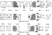
- FIGS. 2a to 2g of the present drawing A possible production sequence with the steps a) to c) and e) to g) is in the FIGS. 2a to 2g of the present drawing.
- a spacer bar between the blade and Glashaltemann is inserted to counteract pressure forces in the vertical compression of the machined wood block and the simultaneous cutting surfaces simultaneously in their geometry, in particular their relative distances as accurate and true to scale to be able to produce.
- step f) is somewhat finer due to the special geometry and the relative positions and dimensions of wing and glass retaining strip, so that in step a) correspondingly an ingot with smaller vertical dimensions than in the system according to reference [5] can be selected.
- the separation cut is always carried out completely. This involves not insignificant safety risks, since the separation cut the two parts are completely detached from each other at the last moment of the separation process and thereby a setback behavior due to the counteracting direction of rotation of the release agent to the feed direction of the two now separate workpieces. This applies in particular if the mechanical force of the feed to the frictional resistance of the support side is in gross disproportion.
- Another disadvantage of the prior art is that usually the separating cut (according to FIGS. 2f and 3f ) takes place after the composition and compression of four elements to a sash. A required constructive 6-sided wood protection of all parts is therefore usually not present in the separation process of the current state of the art.
- Object of the present invention is in contrast, with the simplest possible technical means to provide an inexpensive and cost-effective system of the type described above for fixing a glass, which is particularly easy to handle and should be universally applicable, the need for a special faithfulness and high manufacturing accuracy in the production of the interfaces between the wing and Glashalteance should be avoided.
- the system should still allow precise positioning of the system parts relative to each other.
- the fixation system should also allow for at least largely non-destructive outgassing.
- step f) instead of a complete separation, a predetermined breaking point between glass retaining strip and wing can also be inserted.
- step f) the positioning of the glass retaining strip relative to the wing between step f) and the assembly step g) always takes place in such a way that the length determination of the strip is again correct in relation to the mounting state.
- the present invention proposes a system for fixing a glass pane, which makes it possible to fix the glass pane, for example, on a window or door frame with the aid of a glazing bead.
- the system is characterized by the fact that the separated glazing bead before its assembly with the wing -simultaneously made of the same wooden ingot is rotated relative to its position during manufacture by 180 ° with respect to a vertical axis of rotation.
- This-appearing, but central-measure allows a relative position of wing and Glashaltemann during their simultaneous simultaneous production from the ingot, which allows in step b) to calibrate the ingot only to a vertical height, the only the exact later height the assembly of wing and glass retaining strip in the assembled state, but not - as in the prior art mandatory required - also the thickness d T of the horizontal separating section in manufacturing step f) contains.
- an ingot with a smaller vertical height can already be provided in production step a) than would be possible in the prior art.
- the system according to the invention is particularly simple and inexpensive in terms of manufacture and assembly. It is largely independent of the type of glass used used. Since the system has only low tolerance requirements, it is almost universally applicable, especially for very different glass thicknesses. Nevertheless, the system does not require a larger number of individual elements compared to prior art systems known in the art.
- a glass sheet can be largely vitrified nondestructive, so that then the system can be used again for fixing.
- a repair of a window or a door with glass is considerably simplified.
- Embodiments of the invention are very particularly preferred in which the horizontal separating cut in production step f) is carried out without prior insertion of a spacing strip between the wing and the glass retaining strip.
- this last manufacturing step f) both in the prior art and in the invention, it is absolutely necessary to guide the dressing to be processed from above and below during the horizontal parting cut, for example by means of mechanical clamping or feed rollers.
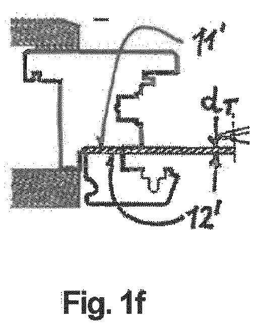
- a certain back pressure is exerted on the bandage. But while in the present invention, this backpressure only on the top and the bottom of the separated blade (see Fig.
- a vertical groove is also simultaneously milled into the lowermost surface of the blade.
- the production step f) does not have to be carried out as a complete separation cut, but the separating cut is carried out so that it leads to a predetermined breaking point, whereby the glass retaining strip is carried in the further manufacturing process, and as needed in the Manufacturing process can also be separated manually.
- the predetermined breaking point has no influence on the rest of the construction. This is of considerable economic importance, especially in the subsequent work processes of the grinding and painting process, because no duplicate part tracking through the manufacturing process is necessary.
- the glass retaining strip in the assembly step g) relative to the wing is arranged such that the glass retaining strip in the installed final state of the system faces the weather side.
- Advantages arise from the fact that the ingots according to FIGS. 1a, 2a and 3a In practice, each consist of multi-layered horizontal slats, which are constructed because of their weather-side position of a particularly weather-resistant or modified wood - in contrast to the room-side wooden slats, which in particular unfold an aesthetic effect. This serves the economic efficiency, in particular both by a longer life cycle of the product as well as a smaller use of warranties due to defect announcements.
- Preferred developments of these embodiments of the invention provide that a different surface treatment of the outer surfaces of the later wing and the later Glashaltemann done in machined ingot, so that in particular two different colors of the later wing and the later Glashaltemann are caused.
- Advantages are that using a cut-cut with predetermined breaking point, the first two operations of wood coating, usually impregnation and priming, can be done on the connected workpiece, whereby significant material savings can be achieved with respect to overspray.
- the workpiece is separated into sash and glazing bead to produce different color surfaces of the sash and the glazing bead.
- the scope of the present invention also includes fixation systems prepared according to the method of the invention described above.
- the wing in the installed state of the system can be designed as a fixed, non-movable frame part.
- An alternative class of embodiments is characterized in that the wing in the assembled state of the system is designed as a movable, in particular pivotable frame part.
- a latching element is provided in the assembled state between the wing and glass retaining strip.
- the locking element fixes the disc and creates a pressure already during the screwing, so that the glass pane is limited in its ability to move.
- the latching element thus assumes the function of a somewhat more complicated form of glass bonding in this embodiment.
- one or more further frame parts preferably also made of wood, can be provided.
- the fixing system has an elongated damping element on its glass-side outer surface in the assembled state, which can be pushed, glued, welded, foamed or sprayed on in particular. This achieves considerable damping of the effective pressure at the end fitting. This It also makes it possible to define the height of the fixation system so that a glazing gasket (see below) can be inserted.
- a flow barrier is provided which prevents uncontrolled air exchange between an outer surface of the frame and an outer surface of the glass sheet.
- This makes it possible for the window frame to have a high thermal resistance, which makes it possible to produce particularly energy-efficient, energy-saving windows. Also, this can prevent unwanted condensation. This is done by forcibly parallel sliding the glass retaining strip on the fixing element. Thus, the glass retaining strip is pressed onto the wing, which in turn prevents an air flow.
- a sealing element between the glass retaining strip and the glass pane may be provided, which engages in the mounted state in a sealing groove of the glass retaining strip.
- the thermal resistance of the window can be optimized if a preferably thermally insulating top strip is arranged in the assembled state between the wing and the glass pane.
- the present invention is concerned with a specially modified system for fixing a glass sheet 10 with two opposing planar, plane-parallel outer surfaces 10 ', 10 " by means of a manufactured from a wooden block 00 Rohlock 11, the glass sheet 10 in the mounted state in a plane perpendicular to their plane-parallel outer surfaces 10 ', 10 "on the wing 11 is seated, and by means of a in the mounted state against one of the outer surfaces 10', 10" adjacent glass retaining strip 12, which is made together with the wing 11 from the same ingot 00.
- a Verklotzungsmaschine 13 may be arranged, against which the glass pane 10 abuts in the assembled state or is seated thereon.
- a fixing element 14 arranged between the glass pane 10 and the glass retaining strip 12 can also be provided, which in the mounted state builds on the glass pane 10 a contact pressure.
- the present invention is characterized that the calibration of the ingot 00 in manufacturing step b) takes place only on the exact later height of the wing 11 and glazing bead 12 assembly in the assembled state, the thickness d T of the horizontal separating cut in manufacturing step f) not being added to the calibration thickness; that between production steps c) and e) a further manufacturing step d) is inserted, namely d) vertical profiling by means of vertical separating cut between the wing 11 and glass retaining strip 12; that before assembly of the wing 11 and glass retaining strip 12 in the assembly step g) the manufactured and from the wing 11 in step f) completely separated glass retaining strip 12 is rotated relative to the wing 11 by 180 ° with respect to a vertical axis of rotation; and that the glass retaining strip 12 is mounted in the assembly step g) relative to the wing 11 such that the glass retaining strip 12 abuts in the mounted state of the system with a surface 12 " on the bottom surface 11" of
- the horizontal separation cut in manufacturing step f) is carried out without prior insertion of a spacer strip 20 between the wing 11 and glass retaining strip 12, as is absolutely necessary in the method according to the prior art (see FIGS. 2f and 3f ).
Landscapes
- Engineering & Computer Science (AREA)
- Civil Engineering (AREA)
- Structural Engineering (AREA)
- Life Sciences & Earth Sciences (AREA)
- Wood Science & Technology (AREA)
- Securing Of Glass Panes Or The Like (AREA)
Abstract
Ein System zur Fixierung einer Glasscheibe (10) durch einen Flügel (11) sowie eine Glashalteleiste (12), die gemeinsam mit dem Flügel (11) aus demselben hölzernen Rohblock (00) gefertigt wird mittels:
a) Bereitstellen des Rohblocks;
b) Kalibrierung auf eine Kalibrierungsdicke DK;
c) Innenprofilierung auf der Glasscheibenseite des Flügels;
e) Außenprofilierung auf der Glasabgewandten Seite;
f) Horizontaler Trennschnitts zwischen Flügel und Glashalteleiste;
g) Zusammenfügen von Flügel und Glashalteleiste
und ist dadurch gekennzeichnet, dass die Kalibrierung des Rohblocks auf die exakte Höhe des Verbands aus Flügel und Glashalteleiste im montierten Zustand erfolgt, wobei die Dicke dT des horizontalen Trennschnitts nicht zur Kalibrierungsdicke hinzugezählt wird;
dass zwischen c) und e) ein weiterer Fertigungsschritt d) "Vertikale Profilierung mittels vertikalem Trennschnitt" erfolgt; dass vor Montageschritt g) die in Schritt f) abgetrennte Glashalteleiste relativ zum Flügel um 180° gedreht und in Ihrer Lage in Relation zur Innenprofilierung und Außenprofilierung des Verbandes derart positioniert wird, dass die Länge der Glashalteleiste im Montageschritt wieder stimmt;
und dass im Montageschritt g) die Glashalteleiste derart montiert wird, dass sie mit einer Fläche (12") an der untersten Fläche (11") des Flügels anliegt, die nicht beim horizontalen Trennschnitt in Fertigungsschritt f) erzeugt wurde.


a) providing the ingot;
b) calibration to a calibration thickness D K ;
c) internal profiling on the glass pane side of the wing;
e) external profiling on the glass side facing away;
f) Horizontal separation between wing and glass retaining strip;
g) Assembly of wing and glass retaining strip
and is characterized in that the calibration of the ingot to the exact height of the wing and glazing bead assembly in the mounted condition is performed, not counting the thickness d T of the horizontal separation cut to the calibration thickness;
that between c) and e) a further production step d) "Vertical profiling by means of vertical separating cut" takes place; that before assembly step g) the glass retaining strip cut off in step f) is rotated relative to the wing by 180 ° and positioned in its position in relation to the internal profiling and external profiling of the dressing such that the length of the glass retaining strip in the assembly step is correct again;
and that in the assembly step g) the glass retaining strip is mounted such that it bears with a surface (12 ") on the lowest surface (11") of the wing, which was not produced in the horizontal separation cut in manufacturing step f).
Description
Die Erfindung betrifft ein System zur Fixierung einer Glasscheibe mit zwei gegenüberliegenden ebenen, planparallelen Außenflächen mittels eines aus einem hölzernen Rohblock gefertigten Flügels, wobei die Glasscheibe im montierten Zustand in einer Ebene senkrecht zu ihren planparallelen Außenflächen auf dem Flügel aufsitzt, sowie mittels einer im montierten Zustand gegen eine der Außenflächen anliegenden Glashalteleiste, die gemeinsam mit dem Flügel aus demselben Rohblock gefertigt wird.
Das Verfahren zur Herstellung dieses Systems umfasst folgende Schritte:
- a) Bereitstellen des Rohblocks aus Holz;
- b) Kalibrierung des Rohblocks durch Hobeln auf eine Kalibrierungsdicke DK, die der exakten späteren Höhe eines Verbands bestehend aus dem Flügel und der Glashalteleiste im montierten Zustand, gegebenenfalls zuzüglich der Dicke dT eines horizontalen Trennschnitts bei der Trennung von Flügel und Glashalteleiste während der Fertigung in Schritt f), entspricht;
- c) Innenprofilierung des Verbands aus Flügel und Glashalteleiste auf der im montierten Zustand des Systems Glasscheiben-zugewandten Seite des Flügels, wobei das Glasfalzmaß hinsichtlich seiner Stärke in Abhängigkeit vom Scheibenaufbau variabel gestaltet ist;
- e)Außenprofilierung des Verbands aus Flügel und Glashalteleiste auf der im montierten Zustand Glasscheiben-abgewandten Seite des Flügels;
- f) Durchführen eines horizontalen Trennschnitts zur Trennung von Flügel und Glashalteleiste in dem in den Schritten b) bis e) bearbeiteten Rohblock; sowie
- g) Montage des Systems mit Zusammenfügen von Flügel und Glashalteleiste.
The process for making this system comprises the following steps:
- a) providing the ingot of wood;
- b) Calibration of the ingot by planing to a calibration thickness D K , the exact later height of a band consisting of the wing and the glass retaining strip in the assembled state, plus, if necessary, the thickness d T of a horizontal separating cut in the separation of the blade and glass retaining strip during manufacture in step f), corresponds;
- c) internal profiling of the wing-and-glazing bead assembly on the side of the wing which is facing the glass pane in the mounted state of the system, wherein the glazing rebate dimension is variable in terms of its thickness depending on the disc structure;
- e) external profiling of the wing and glazing bead assembly on the side of the sash facing away from the glass pane when assembled;
- f) carrying out a horizontal separating cut to separate the wing and the glass retaining strip in the ingot processed in steps b) to e); such as
- g) Assembly of the system with assembly of sash and glazing bead.
Solche Fixierungssysteme für Glasscheiben -und damit grundsätzlich auch deren Herstellungsverfahren- sind beispielsweise bekannt aus
Weitere derartige Systeme werden bereits seit vielen Jahren und von zahlreichen Firmen angeboten.Other such systems have been offered for many years and by many companies.
So bietet die Firma Holzmanufaktur Rottweil, Neckartal 161, D-78628 Rottweil sowohl Neuanfertigungen als auch Rekonstruktionen von historischen, insbesondere auch denkmalgeschützten, klassischen Verbundfenstern (siehe Referenz [4] = Internet-Auftritt http://www.holzmanufaktur-rottweil. de/arbeitsfelder/fenster).
Der entsprechende Fertigungsablauf enthält die eingangs definierten Herstellung-Schritte a) bis c), e) und g). Der horizontale Trennschnitt f) zur Trennung von Flügel und Glashalteleiste ist hier aufgrund der Geometrien und der relativen Lage von Flügel und Glashalteleiste bereits in Schritt e) impliziert.For example, Holzmanufaktur Rottweil, Neckartal 161, D-78628 Rottweil offers both new productions and reconstructions of historical ones, in particular also listed, classical composite windows (see reference [4] = Internet presence http: //www.holzmanufaktur-rottweil.de/de/arbeitfelder/fenster) .
The corresponding production sequence contains the production steps a) to c), e) and g) defined above. The horizontal separating cut f) for separating the wing and the glass retaining strip is here already implied in step e) because of the geometries and the relative position of the wing and the glass retaining strip.
Moderne Trennfenster mit den eingangs definierten Merkmalen bietet etwa die Firma Max Wehrle GmbH, Gewerbestraße 1, D-79183 Waldkirch an (siehe Referenz [5] = Internet-Auftritt http://www.wehrle-fensterbau.de/fenster/holzfenster.php). Ein möglicher Fertigungsablauf mit den Schritten a) bis c) und e) bis g) ist in den
Ein ähnlicher Fertigungsablauf, der ebenfalls die Schritte a) bis c) und e) bis g) umfasst, ist in den
Gegenüber dem oben beschriebenen System nach
Gemeinsam ist den oben diskutierten bekannten Fixierungs-systemen für Glasscheiben unter anderem, dass die beiden Flächen des Flügels und der Glashalteleiste, welche bei deren Trennung -in der Regel im Fertigungsschritt f)- erzeugt werden, später im montierten Verband bei Montageschritt g) miteinander zur Anlage kommen beziehungsweise sich gegenüberliegen, und dass diese beiden Flächen daher besonders maßgenau bearbeitet sein müssen, was entweder aufwändige und teure Nacharbeit oder einen besonders feinen und damit wiederum aufwändigen Trennschnitt erfordert. Außerdem führen die hohen Anforderungen an die Maßtreue bei diesem Fertigungsschritt dazu, dass bereits in Schritt a) ein Rohblock mit deutlich größeren vertikalen Abmessungen bereitgestellt werden muss, als dies im Hinblick auf die vertikalen Endmaße des montierten Verbands eigentlich vonnöten wäre. Damit verbunden ist dann zwangsläufig ein erhöhter Materialverbrauch an Holz.Common to the above-discussed known fixation systems for glass panes, inter alia, that the two surfaces of the wing and the glass retaining strip, which in the separation - usually in the manufacturing step f) - are generated later in the assembled dressing in assembly step g) together Plant come or face each other, and that these two surfaces must therefore be processed particularly accurate to size, which either requires time-consuming and expensive rework or a particularly fine and thus again consuming separation section. In addition, the high standards of dimensional accuracy in this manufacturing step mean that even in step a) an ingot must be provided with significantly larger vertical dimensions than would actually be necessary in view of the vertical final dimensions of the assembled dressing. This is then inevitably an increased consumption of wood.
Weitere Nachteile der bekannten Systeme ergeben sich zudem aus den folgenden Fakten:
Im derzeitigen Stand der Technik soll zwischen der Wetterseitigen Außenfläche der Glashalteleiste und dem Holzrahmen oder wahlweise einer Regenschiene ein definierter Spalt von 0,5 bis 1mm sein, um eine optimale Dichtigkeit des Gesamtelementes zu gewährleisten. Im Trennverfahren gemäß dem Stand der Technik wird aufgrund der erhöhten Toleranz beim Trennschritt f) diese Spaltbreite erhöht, um ein Verblocken der Lackschicht beider Elemente zu verhindern, was zu einer verringerten Gesamtdichtigkeit des Elementes führen kann.Further disadvantages of the known systems also arise from the following facts:
In the current state of the art should be between the weather-side outer surface of the glass retaining strip and the wooden frame or optionally a rain rail a defined gap of 0.5 to 1mm to ensure optimum tightness of the overall element. In the separation method according to the prior art is due to the increased tolerance in the separation step f) increases this gap width in order to prevent blocking of the lacquer layer of both elements, which can lead to a reduced overall tightness of the element.
Weiter wird nach dem Stand der Verfahrenstechnik der Trennschnitt stets vollständig durchgeführt. Dies birgt nicht unerhebliche sicherheitstechnische Risiken, da beim Trennschnitt die beiden Teile im letzten Moment des Trennvorgangs völlig voneinander losgelöst sind und dadurch ein Rückschlag-Verhalten aufgrund der entgegenwirkenden Drehrichtung des Trennmittels zur Vorschubrichtung der beiden nunmehr voneinander getrennten Werkstücke vorliegt. Dies gilt insbesondere, wenn die mechanische Kraft des Vorschubs zum Reibungswiderstand der Auflageseite in einem groben Missverhältnis steht.Furthermore, according to the state of the art, the separation cut is always carried out completely. This involves not insignificant safety risks, since the separation cut the two parts are completely detached from each other at the last moment of the separation process and thereby a setback behavior due to the counteracting direction of rotation of the release agent to the feed direction of the two now separate workpieces. This applies in particular if the mechanical force of the feed to the frictional resistance of the support side is in gross disproportion.
Wie in den
Auch erfolgt beim Stand der Technik eine Positionierung bei der Montage der Glasleiste auf dem bestehenden Flügelrahmen bestenfalls über eine parallel zur Glasauflagefläche vorhandene Nute oder einen Falz. Eine parallel zur äußeren Glasanlagefläche erfolgende Positionierung ergibt sich ausschließlich durch die im Schritt f) erzeugte Trennfläche, welche in der Regel nur von geringer Maßhaltigkeit sein wird. Dieser Konstruktive Nachteil bewirkt jedoch keine positiven Effekte hinsichtlich der Zugkräfte auf die Belastung der Eckverbindung, welche aufgrund höherer Glasgewichte von entscheidender Bedeutung bei der Gesamtkonstruktion ist.Also, in the prior art, positioning occurs during assembly of the glazing bar on the existing sash, at best, via a groove or a groove present parallel to the glazing surface. A positioning which takes place parallel to the outer glass contact surface results exclusively from the parting surface produced in step f), which as a rule is only of minor size Dimensional accuracy will be. However, this design disadvantage does not have any positive effects on the tensile forces on the load of the corner joint, which is of crucial importance in the overall construction due to higher glass weights.
Ein weiterer bedeutender Nachteil im Trennverfahren nach dem Stand der Technik besteht in negativen Effekten hinsichtlich der Wärmeleitfähigkeit in Bezug auf die Gestellung des Rohblockes (siehe
Ein weiterer Nachteil beim Stand der Technik besteht darin, dass üblicherweise der Trennschnitt (gemäß
Schließlich besteht ein weiterer Nachteil beim derzeitigen Stand der Technik darin, dass ohne statische Scheibenverklebung die Windlast und gegebenenfalls eine Sogwirkung physisch auf die Anlagefläche zwischen Flügelrahmen und Glashalteleiste einwirken.Finally, a further disadvantage of the current state of the art is that without static Scheibenverklebung the wind load and possibly a suction effect physically act on the contact surface between casement and Glashalteleiste.
Aufgabe der vorliegenden Erfindung ist es demgegenüber, mit möglichst einfachen technischen Mitteln ein unaufwändiges und kostengünstiges System der eingangs beschriebenen Art zur Fixierung einer Glasscheibe bereit zu stellen, das besonders leicht zu handhaben und möglichst universell einsetzbar sein soll, wobei das Erfordernis einer besonderen Maßtreue und hohe Fertigungsgenauigkeit bei der Herstellung der Trennflächen zwischen Flügel und Glashalteleiste vermieden werden soll. Das System sollte aber dennoch eine präzise Positionierung der Systemteile relativ zueinander ermöglichen. Nicht zuletzt sollte das Fixierungssystem auch ein zumindest weitgehend zerstörungsfreies Ausglasen ermöglichen. Schließlich ist es auch Aufgabe der Erfindung, die Länge des inneren Flügelrahmens zur äußeren Glashalteleiste aufgrund ihrer veränderten Lage so zu verrechnen, dass diese im montierten Zustand wieder der benötigten Länge entsprechen, und keine Nacharbeiten erfordern.Object of the present invention is in contrast, with the simplest possible technical means to provide an inexpensive and cost-effective system of the type described above for fixing a glass, which is particularly easy to handle and should be universally applicable, the need for a special faithfulness and high manufacturing accuracy in the production of the interfaces between the wing and Glashalteleiste should be avoided. However, the system should still allow precise positioning of the system parts relative to each other. Last but not least, the fixation system should also allow for at least largely non-destructive outgassing. Finally, it is also an object of the invention to compensate for the length of the inner sash to the outer Glashalteleiste due to their changed position so that they again correspond to the required length in the assembled state, and require no rework.
Erfindungsgemäß wird diese -relativ komplexe- Aufgabe hinsichtlich der Herstellung des Systems und damit auch durch das zugehörige Verfahrensprodukt auf ebenso überraschend einfache wie wirkungsvolle Weise dadurch gelöst, dass die Kalibrierung des Rohblocks in Fertigungsschritt b) lediglich auf die exakte spätere Höhe des Verbands aus Flügel und Glashalteleiste im montierten Zustand erfolgt, wobei die Dicke dT des horizontalen Trennschnitts in Fertigungsschritt f) nicht zur Kalibrierungsdicke hinzugezählt wird; dass zwischen den Fertigungsschritten c) und e) ein weiterer Fertigungsschritt d) eingefügt wird, nämlich
d) Vertikale Profilierung mittels vertikalem Trennschnitt zwischen Flügel und Glashalteleiste;
dass vor dem Zusammenfügen von Flügel und Glashalteleiste im Montageschritt g) die gefertigte und vom Flügel in Schritt f) vollständig abgetrennte Glashalteleiste relativ zum Flügel um 180° bezüglich einer vertikalen Drehachse gedreht wird -und dadurch in ihrer Lage in Relation zur Innen- und Außenprofilierung des Verbandes derart positioniert ist, dass die Länge der Glashalteleiste im Montageschritt g) wieder stimmt;
und dass die Glashalteleiste im Montageschritt g) relativ zum Flügel derart montiert wird, dass die Glashalteleiste im montierten Zustand des Systems mit einer Fläche an der untersten Fläche des Flügels anliegt, nicht jedoch mit ihrer beim horizontalen Trennschnitt in Fertigungsschritt f) erzeugten Schnittfläche an der Schnittfläche des Flügels, welche durch den horizontalen Trennschnitt in Fertigungsschritt f) simultan erzeugt wurde.According to the invention this relatively complex task with respect to the production of the system and thus also by the associated process product in a surprisingly simple and effective way solved in that the calibration of the ingot in step b) only on the exact subsequent height of the wing and Glashalteleiste done in the assembled state, wherein the thickness d T of the horizontal separation section in manufacturing step f) is not added to the calibration thickness; that between production steps c) and e) a further manufacturing step d) is inserted, namely
d) Vertical profiling by means of a vertical separating cut between the sash and the glazing bead;
that before the assembly of wing and glazing bead in the assembly step g) the manufactured and the wing in step f) completely separated glass retaining strip relative to the wing by 180 ° is rotated with respect to a vertical axis of rotation - and is thus positioned in relation to the inner and outer profiling of the association in such a way that the length of the glass retaining strip in the assembly step g) is correct again;
and that the glass retaining strip is mounted in the assembly step g) relative to the wing such that the glass retaining strip rests in the assembled state of the system with a surface on the bottom surface of the wing, but not with their cut surface at the cut surface produced in the horizontal separation cut in manufacturing step f) of the wing, which was generated simultaneously by the horizontal separating cut in production step f).
Alternativ kann in Schritt f) statt einer vollständigen Abtrennung auch eine Sollbruchstelle zwischen Glashalteleiste und Flügel eingefügt werden.Alternatively, in step f), instead of a complete separation, a predetermined breaking point between glass retaining strip and wing can also be inserted.
In jedem Fall erfolgt die Positionierung der Glashalteleiste relativ zum Flügel zwischen Schritt f) und dem Montageschritt g) immer dergestalt, dass die Längenbestimmung der Leiste wieder in Relation zum Montagezustand korrekt ist.In any case, the positioning of the glass retaining strip relative to the wing between step f) and the assembly step g) always takes place in such a way that the length determination of the strip is again correct in relation to the mounting state.
Die vorliegende Erfindung schlägt also ein System zur Fixierung einer Glasscheibe vor, welches es ermöglicht, mit Hilfe einer Glashalteleiste die Glasscheibe beispielsweise an einem Fenster- oder Türrahmen zu fixieren. Das System zeichnet sich dadurch aus, dass die abgetrennte Glashalteleiste vor ihrer Montage mit dem -simultan aus dem gleichen hölzernen Rohblock gefertigten- zugehörigen Flügel gegenüber ihrer Lage bei der Herstellung um 180° bezüglich einer vertikalen Drehachse gedreht wird.Thus, the present invention proposes a system for fixing a glass pane, which makes it possible to fix the glass pane, for example, on a window or door frame with the aid of a glazing bead. The system is characterized by the fact that the separated glazing bead before its assembly with the wing -simultaneously made of the same wooden ingot is rotated relative to its position during manufacture by 180 ° with respect to a vertical axis of rotation.
Diese -gering erscheinende, jedoch zentrale- Maßnahme ermöglicht eine relative Lage von Flügel und Glashalteleiste während ihrer gemeinsamen simultanen Herstellung aus dem Rohblock, die es erlaubt, in Fertigungsschritt b) den Rohblock lediglich auf eine vertikale Höhe zu kalibrieren, die nur die exakte spätere Höhe des Verbands aus Flügel und Glashalteleiste im montierten Zustand, nicht jedoch -wie im Stand der Technik zwingend erforderlich- auch noch die Dicke dT des horizontalen Trennschnitts in Fertigungsschritt f) enthält. Damit kann also bereits in Fertigungsschritt a) ein Rohblock mit kleinerer vertikaler Höhe bereitgestellt werden, als dies beim Stand der Technik möglich wäre.This-appearing, but central-measure allows a relative position of wing and Glashalteleiste during their simultaneous simultaneous production from the ingot, which allows in step b) to calibrate the ingot only to a vertical height, the only the exact later height the assembly of wing and glass retaining strip in the assembled state, but not - as in the prior art mandatory required - also the thickness d T of the horizontal separating section in manufacturing step f) contains. Thus, an ingot with a smaller vertical height can already be provided in production step a) than would be possible in the prior art.
Aufgrund der oben beschriebenen Drehung der Glashalteleiste um 180° vor ihrer Montage mit dem Flügel können nunmehr auch gänzlich andere Auflageflächen zwischen Flügel und Glashalteleiste gewählt werden als die beim horizontalen Trennschnitt in Fertigungsschritt f) erzeugten Schnittflächen zwischen den beiden Teilen des Verbands. Die Ebene, die die Verbindung zwischen innerem und dem äußeren Rahmenflügel, also zwischen dem Flügel und der Glashalteleiste definiert, wird beim erfindungsgemäßen System nicht mehr durch den Trennschnitt erzeugt, weshalb beim Trennen der beiden Elemente entstehende Toleranzen jetzt nicht mehr relevant sind - im Gegensatz zu allen anderen bekannten Systemen. Da die Qualität der beiden Anlageflächen von besonderer Bedeutung für die Qualität des erzeugten Fixierungssystems ist, ergeben sich damit nunmehr ganz andere und deutlich verbesserte Möglichkeiten für die kosteneffiziente, aber gleichwohl maßgetreue und funktionssichernde Herstellung von derartigen Systemen.Due to the above-described rotation of the glass retaining strip by 180 ° before its assembly with the wing completely different contact surfaces between the wing and glass retaining strip can now be selected as the cut surfaces produced during horizontal separation in step f) between the two parts of the association. The plane which defines the connection between inner and outer frame wings, ie between the wing and the glass retaining strip, is no longer generated by the separating cut in the system according to the invention, which is why tolerances arising during the separation of the two elements are no longer relevant - as opposed to all other known systems. Since the quality of the two contact surfaces is of particular importance for the quality of the fixation system produced, this results in quite different and significantly improved possibilities for the cost-effective, but nevertheless true-to-scale and functionally reliable production of such systems.
Weiter ist das erfindungsgemäße System besonders einfach und kostengünstig in Bezug auf Herstellung und Montage. Es ist weitgehend unabhängig von der Art der verwendeten Glasscheiben einsetzbar. Da das System nur geringe Toleranzanforderungen stellt, ist es nahezu universell verwendbar, insbesondere auch für sehr unterschiedliche Glasstärken. Nichtsdestoweniger benötigt das System aber keine größere Anzahl an Einzelelementen im Vergleich zu den aus dem Stand der Technik bekannten bisherigen Systemen.Further, the system according to the invention is particularly simple and inexpensive in terms of manufacture and assembly. It is largely independent of the type of glass used used. Since the system has only low tolerance requirements, it is almost universally applicable, especially for very different glass thicknesses. Nevertheless, the system does not require a larger number of individual elements compared to prior art systems known in the art.
Auch kann eine Glasscheibe weitgehend zerstörungsfrei ausgeglast werden, so dass anschließend das System zur Fixierung erneut verwendet werden kann. Somit wird beispielsweise eine Reparatur eines Fensters oder einer Tür mit Glasscheibe erheblich vereinfacht.Also, a glass sheet can be largely vitrified nondestructive, so that then the system can be used again for fixing. Thus, for example, a repair of a window or a door with glass is considerably simplified.
Ganz besonders bevorzugt sind Ausführungsformen der Erfindung, bei denen der horizontale Trennschnitt in Fertigungsschritt f) ohne vorheriges Einfügen einer Distanzleiste zwischen Flügel und Glashalteleiste durchgeführt wird. Bei diesem letzten Fertigungsschritt f) ist es -sowohl im Stand der Technik als auch bei der Erfindungunbedingt erforderlich, während des horizontalen Trennschnitts den zu bearbeitenden Verband von oben und von unten zu führen beziehungsweise zu halten, beispielsweise über eine mechanische Klemmung oder über Vorschubrollen. Dazu wird ein gewisser Gegendruck auf den Verband ausgeübt. Während aber bei der vorliegenden Erfindung dieser Gegendruck ausschließlich auf die Oberseite und die Unterseite des abzutrennenden Flügels erfolgt (siehe
Bei weiteren vorteilhaften Ausführungsformen der Erfindung wird in Fertigungsschritt d) zusammen mit dem vertikalen Trennschnitt zwischen Flügel und Glashalteleiste gleichzeitig auch eine vertikale Nut in die unterste Fläche des Flügels gefräst. Dadurch erhält man eine definierte Fläche zur Einbringung eines Klebstoffes, welcher Flügel und Glasleiste statisch verbindet, um Zug- sowie Scherwirkungskräfte, welche auf den Flügel aufgrund hoher Glasgewichte einwirken, aufzufangen. Eine Fugendurchlässigkeit zwischen Flügel und Glasleiste wird bei Eintrag einer Klebemasse sicher verhindert.In further advantageous embodiments of the invention, in production step d) together with the vertical separating cut between the blade and the glazing bead, a vertical groove is also simultaneously milled into the lowermost surface of the blade. This results in a defined area for the introduction of an adhesive which statically connects wings and glazing bead to absorb tensile and shear forces acting on the wing due to high glass weights. A joint permeability between the sash and the glazing bead is reliably prevented when an adhesive is introduced.
Besonders vorteilhaft ist es daher auch, wenn vor dem Zusammenfügen von Flügel und Glashalteleiste im Montageschritt g) Klebstoff in die vertikale Nut eingebracht wird.Therefore, it is also particularly advantageous if, prior to the joining of the wing and the glass retaining strip in the assembly step, g) adhesive is introduced into the vertical groove.
In der Praxis bewähren sich Ausführungsformen der erfindungsgemäßen Vorrichtung, bei welchen vor dem Zusammenfügen von Flügel und Glashalteleiste im Montageschritt g) ein Dichtungselement und/oder Dämmmaterial in einen Spalt zwischen Flügel und Glashalteleiste eingebracht und/oder der Spalt als konstruktiver Luftspalt mit wärmedämmenden Eigenschaften ausgebildet wird. Dies führt zu erheblichen Verbesserungen der Wärmedurchgangs-Koeffizienten ("Lambda") der Gesamtkonstruktion. Auch ohne ein separates Dämmmaterial kann bei dieser Ausführungsform aufgrund einer Luftkammer ein wesentlich besserer Lambda-Wert erzielt werden. Die Wirtschaftlichkeit dieser Ausführungsform erklärt sich aus der aufwendigen Konstruktion etwa einer speziellen Kantel - wie etwa der vom Hersteller Holz-Schiller, Pointenstr. 24-28, D-94209 Regen (siehe deren Internet-Auftritt in Referenz [7]) angebotenen Produkt "Airotherm® Fensterkantel". Durch die Verwendung des Spaltmaßes als Dämmebene können die hohen Beschaffungsinvestitionen in höhere Rohblockware, wie sie in den
Weitere vorteilhafte Ausführungsformen der Erfindung sind dadurch gekennzeichnet, dass der Fertigungsschritt f) nicht als vollständiger Trennschnitt durchgeführt werden muss, sondern der Trennschnitt so ausgeführt wird, dass er zu einer Sollbruchstelle führt, wodurch die Glashalteleiste im weiteren Fertigungsprozess mitgeführt wird, und je nach Bedarf im Fertigungsprozess auch händisch abgetrennt werden kann. Die Sollbruchstelle hat keinerlei Einfluss auf die übrige Konstruktion. Insbesondere bei den weiteren Arbeitsprozessen des Schleif- und Lackiervorganges ist dies von erheblicher wirtschaftlicher Bedeutung, weil keine doppelte Teileverfolgung durch den Fertigungsprozess notwendig wird.Further advantageous embodiments of the invention are characterized in that the production step f) does not have to be carried out as a complete separation cut, but the separating cut is carried out so that it leads to a predetermined breaking point, whereby the glass retaining strip is carried in the further manufacturing process, and as needed in the Manufacturing process can also be separated manually. The predetermined breaking point has no influence on the rest of the construction. This is of considerable economic importance, especially in the subsequent work processes of the grinding and painting process, because no duplicate part tracking through the manufacturing process is necessary.
Besonders bevorzugt sind Ausführungsformen der Erfindung, bei denen die Glashalteleiste im Montageschritt g) relativ zum Flügel derart angeordnet wird, dass die Glashalteleiste im eingebauten Endzustand des Systems der Wetterseite zugewandt ist. Vorteile ergeben sich daraus, dass die Rohblöcke gemäß den
Bevorzugte Weiterbildungen dieser Ausführungsformen der Erfindung sehen vor, dass eine unterschiedliche Oberflächenbehandlung der Außenflächen des späteren Flügels und der späteren Glashalteleiste im bearbeiteten Rohblock erfolgt, so dass insbesondere zwei unterschiedliche Farben des späteren Flügels und der späteren Glashalteleiste hervorgerufen werden. Vorteile bestehen darin, dass unter Verwendung eines Trennschnittes mit Sollbruchstelle die ersten beiden Arbeitsgänge der Holzbeschichtung, in der Regel Imprägnierung und Grundierung, am zusammenhangenden Werkstück erfolgen können, wodurch erhebliche Materialeinsparungen hinsichtlich des Oversprays erzielt werden können. Vorzugsweise wird anschließend und vor der Endlackierung das Werkstück in Flügelrahmen und Glashalteleiste getrennt, um verschiedene Farboberflächen von Flügel und der Glashalteleiste zu erzeugen.Preferred developments of these embodiments of the invention provide that a different surface treatment of the outer surfaces of the later wing and the later Glashalteleiste done in machined ingot, so that in particular two different colors of the later wing and the later Glashalteleiste are caused. Advantages are that using a cut-cut with predetermined breaking point, the first two operations of wood coating, usually impregnation and priming, can be done on the connected workpiece, whereby significant material savings can be achieved with respect to overspray. Preferably, then, and before the final painting, the workpiece is separated into sash and glazing bead to produce different color surfaces of the sash and the glazing bead.
In den Rahmen der vorliegenden Erfindung fallen auch Fixierungssysteme, die nach dem oben geschilderten erfindungsgemäßen Verfahren hergestellt sind.The scope of the present invention also includes fixation systems prepared according to the method of the invention described above.
Dabei kann bei einer ersten Klasse von Ausführungsformen der Flügel im montierten Zustand des Systems als feststehenden, nicht-bewegliches Rahmenteil ausgebildet sein.In this case, in the case of a first class of embodiments, the wing in the installed state of the system can be designed as a fixed, non-movable frame part.
Eine dazu alternative Klasse von Ausführungsformen zeichnet sich dadurch aus, dass der Flügel im montierten Zustand des Systems als bewegliches, insbesondere verschwenkbares Rahmenteil ausgebildet ist.An alternative class of embodiments is characterized in that the wing in the assembled state of the system is designed as a movable, in particular pivotable frame part.
Besonders bevorzugt ist auch eine Ausführungsform, bei welcher im montierten Zustand zwischen Flügel und Glashalteleiste ein Verrastungselement vorgesehen ist. Dies ist von besonderer Bedeutung, da sowohl extreme Windlasten als auch Sogwirkungen auf große Fensterflächen bei hoher Windhöfigkeit zur Wölbung der Glasscheibe führen können. Das Verrastungselement in der besonderen Ausführungsform fixiert die Scheibe und erzeugt bereits bei der Verschraubung einen Druck, sodass die Glasscheibe in ihrer Bewegungsmöglichkeit eingeschränkt wird. Das Verrastungselement übernimmt also in dieser Ausführungsform die Funktion einer etwas aufwändigeren Form der Glasverklebung.Particularly preferred is also an embodiment in which a latching element is provided in the assembled state between the wing and glass retaining strip. This is of particular importance, since both extreme wind loads and suction effects on large window surfaces with high wind resistance can lead to buckling of the glass pane. The locking element in the particular embodiment fixes the disc and creates a pressure already during the screwing, so that the glass pane is limited in its ability to move. The latching element thus assumes the function of a somewhat more complicated form of glass bonding in this embodiment.
Zusätzlich zu Flügel und Glashalteleiste können bei weiteren Ausführungsformen der Erfindung auch ein oder mehrere weitere Rahmenteile, vorzugsweise ebenfalls aus Holz, vorgesehen sein.In addition to the wing and glass retaining strip, in further embodiments of the invention, one or more further frame parts, preferably also made of wood, can be provided.
Bei einer Klasse von vorteilhaften Ausführungsformen weist das Fixierungssystem an seiner im montierten Zustand Glas-seitigen Außenfläche ein längliches Dämpfungselement auf, das insbesondere aufgeschoben, aufgeklebt, aufgeschweißt, aufgeschäumt oder aufgespritzt sein kann. Damit wird eine erhebliche Dämpfung des wirksamen Druckes bei der Endverschraubung erreicht. Dies ermöglicht es auch, die Höhe des Fixierungssystems so zu definieren, dass eine Verglasungsdichtung (siehe unten) eingebracht werden kann.In one class of advantageous embodiments, the fixing system has an elongated damping element on its glass-side outer surface in the assembled state, which can be pushed, glued, welded, foamed or sprayed on in particular. This achieves considerable damping of the effective pressure at the end fitting. This It also makes it possible to define the height of the fixation system so that a glazing gasket (see below) can be inserted.
Bei ergänzenden oder alternativen Weiterbildungen ist es von Vorteil, wenn eine Strömungssperre vorhanden ist, die einen unkontrollierten Luftaustausch zwischen einer Außenfläche des Rahmens und einer Außenfläche der Glasscheibe verhindert. Damit wird es ermöglicht, dass der Fensterrahmen einen hohen Wärmewiderstand aufweist, wodurch sich besonders energieeffiziente, energiesparende Fenster herstellen lassen. Auch kann dadurch einer unerwünschten Kondensatbildung vorgebeugt werden. Dies geschieht durch das zwangsweise parallele Aufschieben der Glashalteleiste auf das Fixierungselement. So wird die Glashalteleiste auf den Flügel aufgedrückt, was wiederum eine Luft-Durchströmung verhindert.In supplemental or alternative developments, it is advantageous if a flow barrier is provided which prevents uncontrolled air exchange between an outer surface of the frame and an outer surface of the glass sheet. This makes it possible for the window frame to have a high thermal resistance, which makes it possible to produce particularly energy-efficient, energy-saving windows. Also, this can prevent unwanted condensation. This is done by forcibly parallel sliding the glass retaining strip on the fixing element. Thus, the glass retaining strip is pressed onto the wing, which in turn prevents an air flow.
Des Weiteren kann bei vorteilhaften Ausführungsformen der Erfindung ein Dichtungselement zwischen der Glashalteleiste und der Glasscheibe vorgesehen sein, welches im montierten Zustand in eine Dichtungsnut der Glashalteleiste eingreift. Mit dieser Ausgestaltung kann dieses Dichtelement gegen die Glasscheibe drücken und sich an dieser abstützen. Dadurch kann es die Glashalteleiste gegen das Selbstverriegelungselement drücken und somit einen zur Arretierung der Glasscheibe notwendigen Druck aufbauen beziehungsweise aufrechterhalten.Furthermore, in advantageous embodiments of the invention, a sealing element between the glass retaining strip and the glass pane may be provided, which engages in the mounted state in a sealing groove of the glass retaining strip. With this configuration, this sealing element can press against the glass pane and be supported on this. As a result, it can press the glass retaining strip against the self-locking element and thus build up or maintain a pressure necessary for locking the glass pane.
Schließlich kann bei Ausführungsformen der Erfindung auch der thermische Widerstand des Fensters optimiert werden, wenn im montierten Zustand zwischen dem Flügel und der Glasscheibe eine vorzugsweise thermisch isolierende Aufsatzleiste angeordnet ist.Finally, in embodiments of the invention, the thermal resistance of the window can be optimized if a preferably thermally insulating top strip is arranged in the assembled state between the wing and the glass pane.
Weitere Merkmale und Vorteile der Erfindung ergeben sich aus der nachfolgenden detaillierten Beschreibung von Ausführungsbeispielen der Erfindung anhand der Figuren der Zeichnung, die erfindungswesentliche Einzelheiten zeigt, sowie aus den Ansprüchen. Die einzelnen Merkmale können je einzeln für sich oder zu mehreren in beliebigen Kombinationen bei Varianten der Erfindung verwirklicht sein.Further features and advantages of the invention will become apparent from the following detailed description of embodiments of the invention with reference to the figures of the drawing, which shows details essential to the invention, and from the claims. The individual features may be implemented individually for themselves or for a plurality of combinations in variants of the invention.
In der schematischen Zeichnung sind Ausführungsbeispiele der Erfindung dargestellt, welche in der nachfolgenden Beschreibung näher erläutert werden.In the schematic drawing embodiments of the invention are shown, which are explained in more detail in the following description.
Im Einzelnen zeigen:
- Fig. 1
- schematische Ansichten der verschiedenen sukzessiven Phasen des Fertigungsablaufs bei der Herstellung einer Ausführungsform des erfindungsgemäßen Fixierungssystems:
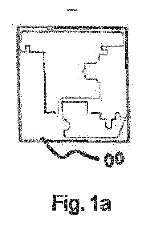
- a) Rohblock aus Holz, aus welchem der spätere Verband von Flügel und Glashalteleiste gefertigt werden soll,
- b) Kalibrierung des Rohblocks durch Hobeln von oben und unten auf eine Kalibrierungsdicke DK,
- c) Innenprofilierung des Verbands durch Bearbeitung des Rohblocks von der -im vorliegenden Bild- linken Seite,
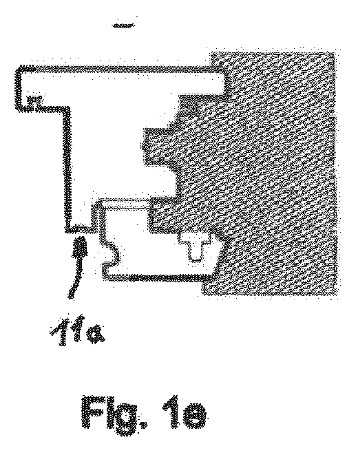
- d)Vertikale Profilierung mittels vertikalem Trennschnitt zwischen Flügel und Glashalteleiste sowie Fräsen einer Nut in die unterste Fläche des Flügels,
- e)Außenprofilierung des Verbands durch Bearbeitung des Rohblocks von der -im vorliegenden Bild- rechten Seite,
- f) horizontaler Trennschnitt zwischen Flügel und Glashalteleiste, und
- g) Montage des Systems mit Drehung der Glashalteleiste um 180° und Zusammenfügen mit dem Flügel;
- Fig. 2
- Fertigungsablauf eines Fixierungssystems nach dem Stand der Technik gemäß Referenz [5], also ohne den erfindungsgemäßen Herstellungsschritt d), jedoch mit Zwischenfügen einer Distanzleiste beim horizontalen Trennschnitt in Schritt f) zwischen Flügel und Glashalteleiste sowie Montage in Schritt g) ohne vorherige Drehung der Glashalteleiste um 180° in anderer Relativposition;
- Fig. 3
- Fertigungsablauf eines Fixierungssystems nach dem Stand der Technik gemäß Referenz [6], also ebenfalls ohne den erfindungsgemäßen Herstellungsschritt d), jedoch mit Zwischenfügen einer Distanzleiste beim horizontalen Trennschnitt in Schritt f) zwischen Flügel und Glashalteleiste sowie Montage in Schritt g) ohne vorherige Drehung der Glashalteleiste um 180° in anderer Relativposition;
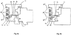
- Fig. 4a
- eine schematische Querschnittsansicht eines Ausführungsbeispiels der Erfindung mit Fixierungselement zwischen der Glashalteleiste und einer Verklotzungsbrücke im montierten Zustand; und
- Fig. 4b
- eine weitere Ausführungsform mit einem Fixierungselement, welches mit einer zusätzlichen Ausbuchtung in eine entsprechende zusätzliche Aufnahmehöhlung der Glashalteleiste eingreift.
- Fig. 1
- schematic views of the various successive stages of the manufacturing process in the production of an embodiment of the fixation system according to the invention:
- a) raw block of wood, from which the later association of wing and glass retaining strip is to be made,
- b) calibration of the ingot by planing from above and below to a calibration thickness D K ,
- c) internal profiling of the dressing by processing the ingot from the left side of the image,
- d) Vertical profiling by means of a vertical separating cut between the blade and glass retaining strip and milling of a groove in the lowest surface of the wing,
- e) external profiling of the dressing by processing the ingot from the -image on the right side,
- f) horizontal separation between wing and glazing bead, and
- g) assembly of the system with rotation of the glazing bead by 180 ° and assembly with the wing;
- Fig. 2
- Production sequence of a fixing system according to the prior art according to reference [5], ie without the manufacturing step d) according to the invention, but with interposing a spacer strip in the horizontal separation cut in step f) between wing and Glashalteleiste and assembly in step g) without prior rotation of the glazing bead to 180 ° in other relative position;
- Fig. 3
- Production sequence of a fixing system according to the prior art according to reference [6], ie also without the inventive production step d), but with interposing a spacer strip in the horizontal separation cut in step f) between wing and glass retaining strip and assembly in step g) without prior rotation of the glass retaining strip 180 ° in other relative position;
- Fig. 4a
- a schematic cross-sectional view of an embodiment of the invention with fixing element between the glass retaining strip and a Verklotzungsbrücke in the assembled state; and
- Fig. 4b
- a further embodiment with a fixing element which engages with an additional bulge in a corresponding additional receiving cavity of the glass retaining strip.
Die vorliegende Erfindung befasst sich mit einem speziell modifizierten System zur Fixierung einer Glasscheibe 10 mit zwei gegenüberliegenden ebenen, planparallelen Außenflächen 10', 10" mittels eines aus einem hölzernen Rohblock 00 gefertigten Flügels 11, wobei die Glasscheibe 10 im montierten Zustand in einer Ebene senkrecht zu ihren planparallelen Außenflächen 10', 10" auf dem Flügel 11 aufsitzt, sowie mittels einer im montierten Zustand gegen eine der Außenflächen 10', 10" anliegenden Glashalteleiste 12, die gemeinsam mit dem Flügel 11 aus demselben Rohblock 00 gefertigt wird.The present invention is concerned with a specially modified system for fixing a glass sheet 10 with two opposing planar, plane-parallel outer surfaces 10 ', 10 " by means of a manufactured from a wooden block 00
Zusätzlich kann zwischen der Glasscheibe 10 und dem Flügel 11 eine Verklotzungsbrücke 13 angeordnet sein, an der im montierten Zustand die Glasscheibe 10 anschlägt beziehungsweise darauf aufsitzt. Auch kann ein zwischen der Glasscheibe 10 und der Glashalteleiste 12 angeordnetes Fixierungselement 14 vorgesehen sein, welches im montierten Zustand auf die Glasscheibe 10 einen Anpressdruck aufbaut.In addition, between the glass pane 10 and the wing 11 a Verklotzungsbrücke 13 may be arranged, against which the glass pane 10 abuts in the assembled state or is seated thereon. A fixing
Details dieser Ausführungsformen sind insbesondere in den
Die Herstellung eines solchen Fixierungssystem umfasst grundsätzlich folgende, bereits aus dem Stand der Technik bekannte Schritte, wie sie insbesondere aus den
- a) Bereitstellen des Rohblocks 00 aus Holz;
- b) Kalibrierung des Rohblocks 00 durch Hobeln auf eine Kalibrierungsdicke DK, die der exakten späteren Höhe eines Verbands bestehend aus
dem Flügel 11 und der Glashalteleiste 12 im montierten Zustand, gegebenenfalls zuzüglich der Dicke dT eines horizontalen Trennschnitts bei derTrennung von Flügel 11 und Glashalteleiste 12 während der Fertigung in Schritt f), entspricht; - c) Innenprofilierung des Verbands aus Flügel 11 und Glashalteleiste 12 auf der im montierten Zustand des Systems Glasscheiben-zugewandten Seite des
Flügels 11; - e) Außenprofilierung des Verbands aus Flügel 11 und Glashalteleiste 12 auf der im montierten Zustand Glasscheiben-abgewandten Seite des
Flügels 11; - f) Durchführen eines horizontalen Trennschnitts zur
Trennung von Flügel 11 und Glashalteleiste 12 in dem in den Schritten b) bis e) bearbeiteten Rohblock 00; sowie - g) Montage des Systems mit
Zusammenfügen von Flügel 11 und Glashalteleiste 12.
- a) providing the ingot 00 from wood;
- b) Calibration of the ingot 00 by planing to a calibration thickness D K , that of the exact later height of a band consisting of the
wing 11 and theglazing bead 12 in the assembled state, optionally plus the thickness d T of a horizontal separating cut in the separation of thewing 11 andglass retaining strip 12 during manufacture in step f), corresponds; - c) internal profiling of the bandage of
wing 11 andglass retaining strip 12 on the glass pane in the mounted state of the system side facing thewing 11; - e) external profiling of the bandage of
wing 11 andglass retaining strip 12 on the side facing away from the glass pane in the mounted state of thewing 11; - f) performing a horizontal separating cut to separate the
wing 11 and theglass retaining strip 12 in the ingot 00 processed in steps b) to e); such as - g) assembly of the system with assembly of
wing 11 and glass retaining strip 12th
Der Trennschnitt ist bei
Wie in den
dass die Kalibrierung des Rohblocks 00 in Fertigungsschritt b) lediglich auf die exakte spätere Höhe des Verbands aus Flügel 11 und Glashalteleiste 12 im montierten Zustand erfolgt, wobei die Dicke dT des horizontalen Trennschnitts in Fertigungsschritt f) nicht zur Kalibrierungsdicke hinzugezählt wird;
dass zwischen den Fertigungsschritten c) und e) ein weiterer Fertigungsschritt d) eingefügt wird, nämlich
d) Vertikale Profilierung mittels vertikalem Trennschnitt zwischen Flügel 11 und Glashalteleiste 12;
dass vor dem Zusammenfügen von Flügel 11 und Glashalteleiste 12 im Montageschritt g) die gefertigte und vom Flügel 11 in Schritt f) vollständig abgetrennte Glashalteleiste 12 relativ zum Flügel 11 um 180° bezüglich einer vertikalen Drehachse gedreht wird;
und dass die Glashalteleiste 12 im Montageschritt g) relativ zum Flügel 11 derart montiert wird, dass die Glashalteleiste 12 im montierten Zustand des Systems mit einer Fläche 12" an der untersten Fläche 11" des Flügels 11 anliegt, nicht jedoch mit ihrer beim horizontalen Trennschnitt in Fertigungsschritt f) erzeugten Schnittfläche 12' an der Schnittfläche 11' des Flügels 11, welche durch den horizontalen Trennschnitt in Fertigungsschritt f) simultan erzeugt wurde.As in the
that the calibration of the ingot 00 in manufacturing step b) takes place only on the exact later height of the
that between production steps c) and e) a further manufacturing step d) is inserted, namely
d) vertical profiling by means of vertical separating cut between the
that before assembly of the
and that the
Insbesondere wird der horizontale Trennschnitt in Fertigungsschritt f) ohne vorheriges Einfügen einer Distanzleiste 20 zwischen Flügel 11 und Glashalteleiste 12 durchgeführt, wie dies bei den Verfahren nach dem Stand der Technik unbedingt erforderlich ist (siehe
Nach dem Montageschritt g) bleibt zwischen der Schnittfläche 11' des Flügels 11 und der Schnittfläche 12' der Glashalteleiste 12 ein Spalt 17, in welchem ein Dichtungselement 15 und/oder Dämmmaterial 16 eingefügt werden kann, wie in den
- 0000
- Rohblock aus HolzRough block of wood
- 1010
- Glasscheibepane
- 10', 10"10 ', 10 "
- Außenflächen der GlasscheibeOuter surfaces of the glass pane
- 1111
- Flügelwing
- 11'11 '
- Schnittfläche des Flügels beim horizontalen TrennschnittCut surface of the wing during horizontal cut
- 11"11 "
- unterste Fläche des Flügelslowest surface of the wing
- 11a11a
- vertikale Nut in der untersten Fläche des Flügelsvertical groove in the bottom surface of the wing
- 1212
- GlashalteleisteGlazing bead
- 12'12 '
- Schnittfläche der Glashalteleiste beim horizontalen TrennschnittCutting surface of the glazing bead during horizontal cutting
- 12"12 "
- Fläche mit der die Glashalteleiste im montierten Zustand an der untersten Fläche des Flügels anliegtSurface with which the glazing bead rests against the bottom surface of the sash when assembled
- 1313
- VerklotzungsbrückeVerklotzungsbrücke
- 1414
- Fixierungselementfixing element
- 1515
- Dichtungselementsealing element
- 1616
- Dämmmaterialinsulation
- 1717
- Spalt zwischen Flügel und GlashalteleisteGap between wing and glass retaining strip
- 2020
- Distanzleiste zwischen Flügel und GlashalteleisteSpacer strip between the wing and glass retaining strip
Für die Beurteilung der Patentfähigkeit in Betracht gezogene Publikationen:
- [1]
DE 20 2015 106 983 U1 - [2]
DE 20 2017 106 284 U1 - [3]
WO 2015 143 462 A1 - [4] http://www.holzmanufaktur-rottweil.de/arbeitsfelder/fenster
- [5] http://www.wehrle-fensterbau.de/fenster/holzfenster.php
- [6] http://www.doerig.ch/unternehmen/produktion.html
- [7] https://www.holz-schiller.de
- [1]
DE 20 2015 106 983 U1 - [2]
DE 20 2017 106 284 U1 - [3]
WO 2015 143 462 A1 - [4] http://www.holzmanufaktur-rottweil.de/arbeitsfelder/fenster
- [5] http://www.wehrle-fensterbau.de/fenster/holzfenster.php
- [6] http://www.doerig.ch/company/production.html
- [7] https://www.holz-schiller.de
Claims (14)
wobei die Herstellung folgende Schritte umfasst:
dass die Kalibrierung des Rohblocks (00) in Fertigungsschritt b) lediglich auf die exakte spätere Höhe des Verbands aus Flügel (11) und Glashalteleiste (12) im montierten Zustand erfolgt, wobei die Dicke dT des horizontalen Trennschnitts in Fertigungsschritt f) nicht zur Kalibrierungsdicke hinzugezählt wird;
dass zwischen den Fertigungsschritten c) und e) ein weiterer Fertigungsschritt d) eingefügt wird, nämlich
d) Vertikale Profilierung mittels vertikalem Trennschnitt zwischen Flügel (11) und Glashalteleiste (12);
dass vor dem Zusammenfügen von Flügel (11) und Glashalteleiste (12) im Montageschritt g) die gefertigte und vom Flügel (11) in Schritt f) vollständig abgetrennte Glashalteleiste (12) relativ zum Flügel (11) um 180° bezüglich einer vertikalen Drehachse gedreht wird;
und dass die Glashalteleiste (12) im Montageschritt g) relativ zum Flügel (11) derart montiert wird, dass die Glashalteleiste (12) im montierten Zustand des Systems mit einer Fläche (12") an der untersten Fläche (11") des Flügels (11) anliegt, nicht jedoch mit ihrer beim horizontalen Trennschnitt in Fertigungsschritt f) erzeugten Schnittfläche (12') an der Schnittfläche (11') des Flügels (11), welche durch den horizontalen Trennschnitt in Fertigungsschritt f) simultan erzeugt wurde.Method for producing a system for fixing a glass pane (10) with two opposite flat, plane-parallel outer surfaces (10 ', 10 ") by means of a wing (11) made of a wooden ingot (00), the glass pane (10) in the installed state in a plane perpendicular to their plane-parallel outer surfaces (10 ', 10 ") on the wing (11) is seated, and by means of a mounted in the assembled state of the system against one of the outer surfaces (10', 10") glass retaining strip (12), the common is made with the wing (11) from the same ingot (00),
the preparation comprising the following steps:
that the calibration of the ingot (00) in step b) only on the exact subsequent height of the wing (11) and Glashalteleiste Association (12) in the assembled state, wherein the thickness d T of the horizontal separation section in manufacturing step f) not to the calibration thickness is added;
that between production steps c) and e) a further manufacturing step d) is inserted, namely
d) Vertical profiling by means of vertical separating section between the wing (11) and glass retaining strip (12);
in that prior to assembly of wing (11) and glazing bead (12) in assembly step g), the glazing bead (12) completely detached from the wing (11) in step f) is rotated relative to the wing (11) by 180 ° with respect to a vertical axis of rotation becomes;
and that the glass retaining strip (12) is mounted in the assembly step g) relative to the wing (11) such that the glass retaining strip (12) in the assembled state of the system with a surface (12 ") on the bottom surface (11") of the wing (11) 11) rests, but not with its in the horizontal separation cut in manufacturing step f) generated cutting surface (12 ') on the cutting surface (11') of the wing (11), which was generated simultaneously by the horizontal separating cut in manufacturing step f).
Applications Claiming Priority (1)
| Application Number | Priority Date | Filing Date | Title |
|---|---|---|---|
| DE102018103559.4A DE102018103559B3 (en) | 2018-02-16 | 2018-02-16 | Glass pane fixing system with wooden frame without loss of separation |
Publications (2)
| Publication Number | Publication Date |
|---|---|
| EP3527770A1 true EP3527770A1 (en) | 2019-08-21 |
| EP3527770B1 EP3527770B1 (en) | 2020-05-13 |
Family
ID=65243435
Family Applications (1)
| Application Number | Title | Priority Date | Filing Date |
|---|---|---|---|
| EP19154280.2A Active EP3527770B1 (en) | 2018-02-16 | 2019-01-29 | Manufacturing method of a system for glass pane fixing with wood frame without separation loss |
Country Status (2)
| Country | Link |
|---|---|
| EP (1) | EP3527770B1 (en) |
| DE (1) | DE102018103559B3 (en) |
Families Citing this family (2)
| Publication number | Priority date | Publication date | Assignee | Title |
|---|---|---|---|---|
| IT201900010170A1 (en) * | 2019-06-26 | 2020-12-26 | Sciuker Frames S P A | Method for the construction of window frames, kit for the construction of a window and door frame |
| DE102020116297A1 (en) * | 2020-06-19 | 2021-12-23 | Urban Gesellschaft mit beschränkter Haftung & Co. Maschinenbau Kommanditgesellschaft | Method and device for machining an end region of a profile |
Citations (2)
| Publication number | Priority date | Publication date | Assignee | Title |
|---|---|---|---|---|
| DE19820409A1 (en) * | 1998-05-07 | 1999-11-18 | Ingbuero Roob Gmbh | Manufacturing method for rebated glass batten for doors and windows |
| DE202017106284U1 (en) * | 2017-10-17 | 2017-11-13 | Zuani Deutschland Gmbh | Fixed glazing system for fixing a glazing bead with definable contact pressure |
Family Cites Families (2)
| Publication number | Priority date | Publication date | Assignee | Title |
|---|---|---|---|---|
| AT515424B1 (en) | 2014-03-24 | 2015-09-15 | Goll Jürgen | Method for fastening or fixing glass panes |
| DE202015106983U1 (en) | 2015-12-22 | 2016-01-21 | Zuani Deutschland Gmbh | System for boltless fixation of a glass pane |
-
2018
- 2018-02-16 DE DE102018103559.4A patent/DE102018103559B3/en active Active
-
2019
- 2019-01-29 EP EP19154280.2A patent/EP3527770B1/en active Active
Patent Citations (2)
| Publication number | Priority date | Publication date | Assignee | Title |
|---|---|---|---|---|
| DE19820409A1 (en) * | 1998-05-07 | 1999-11-18 | Ingbuero Roob Gmbh | Manufacturing method for rebated glass batten for doors and windows |
| DE202017106284U1 (en) * | 2017-10-17 | 2017-11-13 | Zuani Deutschland Gmbh | Fixed glazing system for fixing a glazing bead with definable contact pressure |
Also Published As
| Publication number | Publication date |
|---|---|
| EP3527770B1 (en) | 2020-05-13 |
| DE102018103559B3 (en) | 2019-05-16 |
Similar Documents
| Publication | Publication Date | Title |
|---|---|---|
| EP1943406B1 (en) | Constituent element | |
| CH699782A2 (en) | Frame connector for attachment to a frame. | |
| EP4092240A1 (en) | New gluing technique for mounting windows | |
| DE202015106983U1 (en) | System for boltless fixation of a glass pane | |
| DE29916942U1 (en) | Composite window | |
| EP3527770B1 (en) | Manufacturing method of a system for glass pane fixing with wood frame without separation loss | |
| DE2840656A1 (en) | Hollow plastics bar door or window frame - has internally hollow extruded metal sections held together inside plastics at corners by perpendicular screws | |
| DE202018100885U1 (en) | Glass pane fixing system with wooden frame without loss of separation | |
| EP2405093B1 (en) | Modular flame retardant glazing | |
| EP1983123B1 (en) | Facade construction with reduced linear heat flow coefficients | |
| EP1500769B1 (en) | Wooden window system | |
| EP2312104A1 (en) | Fire resistant door | |
| DE19749775C2 (en) | Window or door sash | |
| EP3473796A1 (en) | Fixed glazing system for fixing a glass retaining strip with definable contact pressure | |
| EP0746658B1 (en) | Insulating arrangement for facades | |
| DE19745319C1 (en) | Glazed wall panel for building | |
| DE102006054427B4 (en) | Alu-plastic window with adhesive tape fixation | |
| EP2236723B1 (en) | Method of making a corner connection with hollow plastic profiles | |
| DE29811431U1 (en) | Window, door, facade element or the like. | |
| EP2314817B1 (en) | Sound insulation door | |
| EP2295697A2 (en) | Method for producing a window or a door | |
| EP2463471B1 (en) | Method for connecting wall sections | |
| EP1980702B1 (en) | Frame construction for windows and/or doors | |
| EP4438843A1 (en) | A structure for the replacement of an insulating glazing of a structure for the rotation of a structure for the rotation of a building | |
| DE10212204A1 (en) | Window frame has insulating layers attached to sill and frame around pane, seal being fitted between insulating layer and pane and outer frames being attached to insulating layers |
Legal Events
| Date | Code | Title | Description |
|---|---|---|---|
| PUAI | Public reference made under article 153(3) epc to a published international application that has entered the european phase |
Free format text: ORIGINAL CODE: 0009012 |
|
| STAA | Information on the status of an ep patent application or granted ep patent |
Free format text: STATUS: THE APPLICATION HAS BEEN PUBLISHED |
|
| AK | Designated contracting states |
Kind code of ref document: A1 Designated state(s): AL AT BE BG CH CY CZ DE DK EE ES FI FR GB GR HR HU IE IS IT LI LT LU LV MC MK MT NL NO PL PT RO RS SE SI SK SM TR |
|
| AX | Request for extension of the european patent |
Extension state: BA ME |
|
| STAA | Information on the status of an ep patent application or granted ep patent |
Free format text: STATUS: REQUEST FOR EXAMINATION WAS MADE |
|
| 17P | Request for examination filed |
Effective date: 20191016 |
|
| RBV | Designated contracting states (corrected) |
Designated state(s): AL AT BE BG CH CY CZ DE DK EE ES FI FR GB GR HR HU IE IS IT LI LT LU LV MC MK MT NL NO PL PT RO RS SE SI SK SM TR |
|
| GRAP | Despatch of communication of intention to grant a patent |
Free format text: ORIGINAL CODE: EPIDOSNIGR1 |
|
| STAA | Information on the status of an ep patent application or granted ep patent |
Free format text: STATUS: GRANT OF PATENT IS INTENDED |
|
| INTG | Intention to grant announced |
Effective date: 20200110 |
|
| GRAS | Grant fee paid |
Free format text: ORIGINAL CODE: EPIDOSNIGR3 |
|
| GRAA | (expected) grant |
Free format text: ORIGINAL CODE: 0009210 |
|
| STAA | Information on the status of an ep patent application or granted ep patent |
Free format text: STATUS: THE PATENT HAS BEEN GRANTED |
|
| AK | Designated contracting states |
Kind code of ref document: B1 Designated state(s): AL AT BE BG CH CY CZ DK EE ES FI FR GB GR HR HU IE IS IT LI LT LU LV MC MK MT NL NO PL PT RO RS SE SI SK SM TR |
|
| RBV | Designated contracting states (corrected) |
Designated state(s): AL AT BE BG CH CY CZ DK EE ES FI FR GB GR HR HU IE IS IT LI LT LU LV MC MK MT NL NO PL PT RO RS SE SI SK SM TR |
|
| REG | Reference to a national code |
Ref country code: GB Ref legal event code: FG4D Free format text: NOT ENGLISH Ref country code: DE Ref legal event code: R108 |
|
| REG | Reference to a national code |
Ref country code: CH Ref legal event code: EP |
|
| REG | Reference to a national code |
Ref country code: AT Ref legal event code: REF Ref document number: 1270498 Country of ref document: AT Kind code of ref document: T Effective date: 20200615 |
|
| REG | Reference to a national code |
Ref country code: CH Ref legal event code: NV Representative=s name: ROTTMANN, ZIMMERMANN + PARTNER AG, CH |
|
| REG | Reference to a national code |
Ref country code: LT Ref legal event code: MG4D |
|
| REG | Reference to a national code |
Ref country code: NL Ref legal event code: MP Effective date: 20200513 |
|
| PG25 | Lapsed in a contracting state [announced via postgrant information from national office to epo] |
Ref country code: LT Free format text: LAPSE BECAUSE OF FAILURE TO SUBMIT A TRANSLATION OF THE DESCRIPTION OR TO PAY THE FEE WITHIN THE PRESCRIBED TIME-LIMIT Effective date: 20200513 Ref country code: FI Free format text: LAPSE BECAUSE OF FAILURE TO SUBMIT A TRANSLATION OF THE DESCRIPTION OR TO PAY THE FEE WITHIN THE PRESCRIBED TIME-LIMIT Effective date: 20200513 Ref country code: IS Free format text: LAPSE BECAUSE OF FAILURE TO SUBMIT A TRANSLATION OF THE DESCRIPTION OR TO PAY THE FEE WITHIN THE PRESCRIBED TIME-LIMIT Effective date: 20200913 Ref country code: SE Free format text: LAPSE BECAUSE OF FAILURE TO SUBMIT A TRANSLATION OF THE DESCRIPTION OR TO PAY THE FEE WITHIN THE PRESCRIBED TIME-LIMIT Effective date: 20200513 Ref country code: GR Free format text: LAPSE BECAUSE OF FAILURE TO SUBMIT A TRANSLATION OF THE DESCRIPTION OR TO PAY THE FEE WITHIN THE PRESCRIBED TIME-LIMIT Effective date: 20200814 Ref country code: NO Free format text: LAPSE BECAUSE OF FAILURE TO SUBMIT A TRANSLATION OF THE DESCRIPTION OR TO PAY THE FEE WITHIN THE PRESCRIBED TIME-LIMIT Effective date: 20200813 Ref country code: PT Free format text: LAPSE BECAUSE OF FAILURE TO SUBMIT A TRANSLATION OF THE DESCRIPTION OR TO PAY THE FEE WITHIN THE PRESCRIBED TIME-LIMIT Effective date: 20200914 |
|
| PG25 | Lapsed in a contracting state [announced via postgrant information from national office to epo] |
Ref country code: HR Free format text: LAPSE BECAUSE OF FAILURE TO SUBMIT A TRANSLATION OF THE DESCRIPTION OR TO PAY THE FEE WITHIN THE PRESCRIBED TIME-LIMIT Effective date: 20200513 Ref country code: RS Free format text: LAPSE BECAUSE OF FAILURE TO SUBMIT A TRANSLATION OF THE DESCRIPTION OR TO PAY THE FEE WITHIN THE PRESCRIBED TIME-LIMIT Effective date: 20200513 Ref country code: LV Free format text: LAPSE BECAUSE OF FAILURE TO SUBMIT A TRANSLATION OF THE DESCRIPTION OR TO PAY THE FEE WITHIN THE PRESCRIBED TIME-LIMIT Effective date: 20200513 Ref country code: BG Free format text: LAPSE BECAUSE OF FAILURE TO SUBMIT A TRANSLATION OF THE DESCRIPTION OR TO PAY THE FEE WITHIN THE PRESCRIBED TIME-LIMIT Effective date: 20200813 |
|
| PG25 | Lapsed in a contracting state [announced via postgrant information from national office to epo] |
Ref country code: AL Free format text: LAPSE BECAUSE OF FAILURE TO SUBMIT A TRANSLATION OF THE DESCRIPTION OR TO PAY THE FEE WITHIN THE PRESCRIBED TIME-LIMIT Effective date: 20200513 Ref country code: NL Free format text: LAPSE BECAUSE OF FAILURE TO SUBMIT A TRANSLATION OF THE DESCRIPTION OR TO PAY THE FEE WITHIN THE PRESCRIBED TIME-LIMIT Effective date: 20200513 |
|
| PG25 | Lapsed in a contracting state [announced via postgrant information from national office to epo] |
Ref country code: IT Free format text: LAPSE BECAUSE OF FAILURE TO SUBMIT A TRANSLATION OF THE DESCRIPTION OR TO PAY THE FEE WITHIN THE PRESCRIBED TIME-LIMIT Effective date: 20200513 Ref country code: EE Free format text: LAPSE BECAUSE OF FAILURE TO SUBMIT A TRANSLATION OF THE DESCRIPTION OR TO PAY THE FEE WITHIN THE PRESCRIBED TIME-LIMIT Effective date: 20200513 Ref country code: DK Free format text: LAPSE BECAUSE OF FAILURE TO SUBMIT A TRANSLATION OF THE DESCRIPTION OR TO PAY THE FEE WITHIN THE PRESCRIBED TIME-LIMIT Effective date: 20200513 Ref country code: SM Free format text: LAPSE BECAUSE OF FAILURE TO SUBMIT A TRANSLATION OF THE DESCRIPTION OR TO PAY THE FEE WITHIN THE PRESCRIBED TIME-LIMIT Effective date: 20200513 Ref country code: ES Free format text: LAPSE BECAUSE OF FAILURE TO SUBMIT A TRANSLATION OF THE DESCRIPTION OR TO PAY THE FEE WITHIN THE PRESCRIBED TIME-LIMIT Effective date: 20200513 Ref country code: CZ Free format text: LAPSE BECAUSE OF FAILURE TO SUBMIT A TRANSLATION OF THE DESCRIPTION OR TO PAY THE FEE WITHIN THE PRESCRIBED TIME-LIMIT Effective date: 20200513 Ref country code: RO Free format text: LAPSE BECAUSE OF FAILURE TO SUBMIT A TRANSLATION OF THE DESCRIPTION OR TO PAY THE FEE WITHIN THE PRESCRIBED TIME-LIMIT Effective date: 20200513 |
|
| PG25 | Lapsed in a contracting state [announced via postgrant information from national office to epo] |
Ref country code: SK Free format text: LAPSE BECAUSE OF FAILURE TO SUBMIT A TRANSLATION OF THE DESCRIPTION OR TO PAY THE FEE WITHIN THE PRESCRIBED TIME-LIMIT Effective date: 20200513 Ref country code: PL Free format text: LAPSE BECAUSE OF FAILURE TO SUBMIT A TRANSLATION OF THE DESCRIPTION OR TO PAY THE FEE WITHIN THE PRESCRIBED TIME-LIMIT Effective date: 20200513 |
|
| PLBE | No opposition filed within time limit |
Free format text: ORIGINAL CODE: 0009261 |
|
| STAA | Information on the status of an ep patent application or granted ep patent |
Free format text: STATUS: NO OPPOSITION FILED WITHIN TIME LIMIT |
|
| 26N | No opposition filed |
Effective date: 20210216 |
|
| PG25 | Lapsed in a contracting state [announced via postgrant information from national office to epo] |
Ref country code: MC Free format text: LAPSE BECAUSE OF FAILURE TO SUBMIT A TRANSLATION OF THE DESCRIPTION OR TO PAY THE FEE WITHIN THE PRESCRIBED TIME-LIMIT Effective date: 20200513 |
|
| PG25 | Lapsed in a contracting state [announced via postgrant information from national office to epo] |
Ref country code: LU Free format text: LAPSE BECAUSE OF NON-PAYMENT OF DUE FEES Effective date: 20210129 |
|
| REG | Reference to a national code |
Ref country code: BE Ref legal event code: MM Effective date: 20210131 |
|
| PG25 | Lapsed in a contracting state [announced via postgrant information from national office to epo] |
Ref country code: FR Free format text: LAPSE BECAUSE OF NON-PAYMENT OF DUE FEES Effective date: 20210131 |
|
| PG25 | Lapsed in a contracting state [announced via postgrant information from national office to epo] |
Ref country code: IE Free format text: LAPSE BECAUSE OF NON-PAYMENT OF DUE FEES Effective date: 20210129 |
|
| PG25 | Lapsed in a contracting state [announced via postgrant information from national office to epo] |
Ref country code: BE Free format text: LAPSE BECAUSE OF NON-PAYMENT OF DUE FEES Effective date: 20210131 |
|
| PG25 | Lapsed in a contracting state [announced via postgrant information from national office to epo] |
Ref country code: CY Free format text: LAPSE BECAUSE OF FAILURE TO SUBMIT A TRANSLATION OF THE DESCRIPTION OR TO PAY THE FEE WITHIN THE PRESCRIBED TIME-LIMIT Effective date: 20200513 |
|
| PG25 | Lapsed in a contracting state [announced via postgrant information from national office to epo] |
Ref country code: HU Free format text: LAPSE BECAUSE OF FAILURE TO SUBMIT A TRANSLATION OF THE DESCRIPTION OR TO PAY THE FEE WITHIN THE PRESCRIBED TIME-LIMIT; INVALID AB INITIO Effective date: 20190129 |
|
| GBPC | Gb: european patent ceased through non-payment of renewal fee |
Effective date: 20230129 |
|
| PG25 | Lapsed in a contracting state [announced via postgrant information from national office to epo] |
Ref country code: SI Free format text: LAPSE BECAUSE OF FAILURE TO SUBMIT A TRANSLATION OF THE DESCRIPTION OR TO PAY THE FEE WITHIN THE PRESCRIBED TIME-LIMIT Effective date: 20200513 |
|
| PG25 | Lapsed in a contracting state [announced via postgrant information from national office to epo] |
Ref country code: GB Free format text: LAPSE BECAUSE OF NON-PAYMENT OF DUE FEES Effective date: 20230129 |
|
| PG25 | Lapsed in a contracting state [announced via postgrant information from national office to epo] |
Ref country code: MK Free format text: LAPSE BECAUSE OF FAILURE TO SUBMIT A TRANSLATION OF THE DESCRIPTION OR TO PAY THE FEE WITHIN THE PRESCRIBED TIME-LIMIT Effective date: 20200513 |
|
| PG25 | Lapsed in a contracting state [announced via postgrant information from national office to epo] |
Ref country code: TR Free format text: LAPSE BECAUSE OF FAILURE TO SUBMIT A TRANSLATION OF THE DESCRIPTION OR TO PAY THE FEE WITHIN THE PRESCRIBED TIME-LIMIT Effective date: 20200513 |
|
| PG25 | Lapsed in a contracting state [announced via postgrant information from national office to epo] |
Ref country code: MT Free format text: LAPSE BECAUSE OF FAILURE TO SUBMIT A TRANSLATION OF THE DESCRIPTION OR TO PAY THE FEE WITHIN THE PRESCRIBED TIME-LIMIT Effective date: 20200513 |
|
| REG | Reference to a national code |
Ref country code: CH Ref legal event code: U11 Free format text: ST27 STATUS EVENT CODE: U-0-0-U10-U11 (AS PROVIDED BY THE NATIONAL OFFICE) Effective date: 20260201 |
|
| REG | Reference to a national code |
Ref country code: CH Ref legal event code: R17 Free format text: ST27 STATUS EVENT CODE: U-0-0-R10-R17 (AS PROVIDED BY THE NATIONAL OFFICE) Effective date: 20260410 |
|
| PGFP | Annual fee paid to national office [announced via postgrant information from national office to epo] |
Ref country code: AT Payment date: 20260119 Year of fee payment: 8 |
|
| PGFP | Annual fee paid to national office [announced via postgrant information from national office to epo] |
Ref country code: CH Payment date: 20260201 Year of fee payment: 8 |