EP3523157B1 - Fahrzeugsitz, insbesondere kraftfahrzeugsitz - Google Patents
Fahrzeugsitz, insbesondere kraftfahrzeugsitz Download PDFInfo
- Publication number
- EP3523157B1 EP3523157B1 EP17777044.3A EP17777044A EP3523157B1 EP 3523157 B1 EP3523157 B1 EP 3523157B1 EP 17777044 A EP17777044 A EP 17777044A EP 3523157 B1 EP3523157 B1 EP 3523157B1
- Authority
- EP
- European Patent Office
- Prior art keywords
- fitting
- vehicle seat
- backrest
- spring element
- structural part
- Prior art date
- Legal status (The legal status is an assumption and is not a legal conclusion. Google has not performed a legal analysis and makes no representation as to the accuracy of the status listed.)
- Active
Links
Images


Classifications
-
- B—PERFORMING OPERATIONS; TRANSPORTING
- B60—VEHICLES IN GENERAL
- B60N—SEATS SPECIALLY ADAPTED FOR VEHICLES; VEHICLE PASSENGER ACCOMMODATION NOT OTHERWISE PROVIDED FOR
- B60N2/00—Seats specially adapted for vehicles; Arrangement or mounting of seats in vehicles
- B60N2/02—Seats specially adapted for vehicles; Arrangement or mounting of seats in vehicles the seat or part thereof being movable, e.g. adjustable
- B60N2/20—Seats specially adapted for vehicles; Arrangement or mounting of seats in vehicles the seat or part thereof being movable, e.g. adjustable the back-rest being tiltable, e.g. to permit easy access
- B60N2/206—Seats specially adapted for vehicles; Arrangement or mounting of seats in vehicles the seat or part thereof being movable, e.g. adjustable the back-rest being tiltable, e.g. to permit easy access to a position in which it can be used as a support for objects, e.g. as a tray
-
- B—PERFORMING OPERATIONS; TRANSPORTING
- B60—VEHICLES IN GENERAL
- B60N—SEATS SPECIALLY ADAPTED FOR VEHICLES; VEHICLE PASSENGER ACCOMMODATION NOT OTHERWISE PROVIDED FOR
- B60N2/00—Seats specially adapted for vehicles; Arrangement or mounting of seats in vehicles
- B60N2/02—Seats specially adapted for vehicles; Arrangement or mounting of seats in vehicles the seat or part thereof being movable, e.g. adjustable
- B60N2/22—Seats specially adapted for vehicles; Arrangement or mounting of seats in vehicles the seat or part thereof being movable, e.g. adjustable the back-rest being adjustable
- B60N2/235—Seats specially adapted for vehicles; Arrangement or mounting of seats in vehicles the seat or part thereof being movable, e.g. adjustable the back-rest being adjustable by gear-pawl type mechanisms
- B60N2/2356—Seats specially adapted for vehicles; Arrangement or mounting of seats in vehicles the seat or part thereof being movable, e.g. adjustable the back-rest being adjustable by gear-pawl type mechanisms with internal pawls
- B60N2/236—Seats specially adapted for vehicles; Arrangement or mounting of seats in vehicles the seat or part thereof being movable, e.g. adjustable the back-rest being adjustable by gear-pawl type mechanisms with internal pawls linearly movable
Definitions
- the invention relates to a vehicle seat, in particular a motor vehicle seat, with a first structural part, a second structural part and at least one lockable and unlockable fitting, the fitting having a first fitting part which is at least indirectly connected to the first structural part, and a second fitting part which is at least indirectly connected is connected to the second structural part, wherein when the fitting is unlocked, an angular position of the second structural part relative to the first structural part can be changed about an axis, the first structural part being a seat part structure of a seat part, and the second structural part being a backrest structure of a backrest , and the vehicle seat can assume a use position suitable for passenger transport, in which the backrest is largely upright, and can assume a non-use position, in which the backrest is pivoted forwards about the axis relative to the use position.
- a locking fitting for a vehicle seat having a fitting lower part, a fitting upper part rotatably mounted on the fitting lower part and at least one toothed segment guided in a guide of the fitting lower part for locking the fitting upper part, the guide also forming the bearing for the fitting upper part.
- Spacers made of a plastic are provided between the guide and the upper part of the fitting.
- the DE 10 2004 041 735 A1 discloses a fitting for a vehicle seat, with a first fitting part, a second fitting part which can be pivoted about an axis relative to the first fitting part, at least one retaining clip for axially holding the fitting parts together and at least one slider for eliminating radial play between the fitting parts.
- the slider eliminates the radial play in all angular positions of the second fitting part relative to the first fitting part.
- the DE 101 20 854 C1 discloses a gear fitting for a vehicle seat adjustment device with a first ring gear and a second ring gear which is rotatably mounted relative to this and is arranged axially thereto as central ring gears and at least one rotating ring gear which is arranged axially between the ring gears and meshes with both ring gears Planet gear, wherein the second ring gear is mounted on the first ring gear with the interposition of a wave-shaped and/or polygonal bearing bush.
- the WO 2005/068249 A1 discloses a vehicle seat with a first structural part, a second structural part and a lockable and unlockable fitting, the fitting having a first fitting part which is connected to the first structural part and a second fitting part which is connected to the second structural part, with the fitting being unlocked an angular position of the second structural part relative to the first structural part can be changed about an axis, with the vehicle seat being able to assume a position of use suitable for transporting people, in which the backrest is largely upright, and a position of non-use in which the backrest is around the position in relation to the position of use Axis is pivoted forward.
- the invention is based on the object of improving a vehicle seat of the type mentioned at the outset, in particular of avoiding noise due to radial play of the fitting in an unlocked state.
- a vehicle seat in particular a motor vehicle seat, with a first structural part, a second structural part and at least one lockable and unlockable fitting, the fitting having a first fitting part which is at least indirectly connected to the first structural part, and a second fitting part, which is connected at least indirectly to the second structural part, wherein when the fitting is unlocked, an angular position of the second structural part relative to the first structural part can be changed about an axis, the first structural part being a seat part structure of a seat part, and the second structural part being a backrest structure a backrest, and the vehicle seat is one for passenger transport can assume a suitable use position, in which the backrest is largely upright, and a non-use position, in which the backrest is pivoted forwards about the axis relative to the use position, with a spring element in at least one angular position of the second structural part relative to the first structural part first fitting part and the second fitting part braced against one another in the radial direction, and in at least
- the spring element has no effect on the fitting in at least one further angular position, so that the spring element enables low-friction adjustment of the fitting over defined angular ranges, the spring element having no effect on the fitting in the position of use, and the spring element in the position of non-use is the first fitting part and the second fitting part braced against each other in the radial direction.
- the fitting is preferably designed as a detent fitting, the basic functioning of which, for example, in the WO 2014/053400 A1 is described.
- the first structural part is a seat part structure of a seat part
- the second structural part is a backrest structure of a backrest, the fitting serving to adjust the inclination of the backrest.
- the vehicle seat preferably has two fittings, namely one fitting on each side of the seat.
- the first fitting part can be connected to the seat part structure by means of a first adapter. However, a direct connection of the first fitting part to the seat part structure is also possible.
- the second fitting part can be connected to the backrest structure by means of a second adapter. It is however, a direct connection of the second fitting part to the backrest structure is also possible.
- the vehicle seat can assume at least one position of use suitable for transporting people, in which the backrest is largely upright. To improve comfort, the vehicle seat can assume several positions of use within an adjustment range, in particular in angular positions that are stepped relative to one another. The at least one fitting is locked in the at least one position of use, and possibly further positions of use, during normal use of the vehicle seat for transporting people.
- the vehicle seat can assume a non-use position in which the backrest is pivoted forwards about the axis relative to the use position.
- the backrest In the non-use position, the backrest is preferably pivoted into a largely horizontal position.
- the back of the backrest can serve as a loading floor when not in use.
- the fitting is preferably not locked in the non-use position.
- the backrest In the non-use position, the backrest can rest with a backrest cushion on a seat part cushion of the seat part.
- the spring element In the position of use, the spring element has no effect on the fitting, so that the spring element enables the inclination of the backrest to be adjusted with little friction between a number of positions of use.
- the spring element In the non-use position, the spring element braces the first fitting part and the second fitting part against one another in the radial direction.
- the spring element In an intermediate position between the position of use and the position of non-use, the spring element can brace the first fitting part and the second fitting part against one another in the radial direction.
- the spring element is preferably wedge-shaped.
- the spring element preferably acts in the radial direction like a wedge between the two fitting parts.
- the spring element can have a run-on bevel running in the shape of a wedge in the circumferential direction exhibit.
- the spring element can be supported on one of the two fitting parts in the radial direction.
- the spring element can be fastened in a stationary manner to this one of the two fitting parts.
- a finger can brace the spring element in the at least one angular position of the second structural part relative to the first structural part in the radial direction.
- the finger can pivot about the axis with the other of the two fitting parts.
- the finger is attached to a backrest structure or an adapter connected to the backrest structure.
- a radially inwardly facing inner surface of the finger may be curved circumferentially at a radius about the back pivot axis.
- the finger When assuming at least one angular position, the finger can run onto a flange of the spring element.
- the flange may include at least one flange portion that is radially outwardly disposed than a radially inwardly facing surface of the finger.
- a longitudinal direction x runs largely horizontally and preferably parallel to a longitudinal direction of the vehicle, which corresponds to the usual direction of travel of the vehicle.
- a transverse direction y running perpendicularly to the longitudinal direction x is likewise aligned horizontally in the vehicle and runs parallel to a vehicle transverse direction.
- a vertical direction z runs perpendicular to the longitudinal direction x and perpendicular to the transverse direction y.
- the vertical direction z runs parallel to the vertical axis of the vehicle.
- the position and direction information used such as front, rear, up and down, relates to a viewing direction of an occupant seated in the vehicle seat 1, 51 in a normal seating position, with the vehicle seat 1, 51 installed in the vehicle, in a position of use suitable for passenger transport and oriented in the direction of travel as usual.
- the vehicle seat 1, 51 according to the invention can also be installed in a different orientation, for example transverse to the direction of travel.
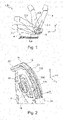
- figure 1 shows a schematic side view of the vehicle seat 1, 51, the backrest 5 being shown in a use position 5.1, a non-use position 5.4 and two intermediate positions 5.2, 5.3 located between the use position 5.1 and the non-use position 5.4.
- the backrest 5 In the position of use 5.1, the backrest 5 is inclined slightly backwards relative to the vertical direction z. The position of use of the backrest 5 serves in particular to transport people.
- the backrest 5 is pivoted about an axis A parallel to the transverse direction y, hereinafter also referred to as the backrest pivot axis A, pivoted so far forward that the The backrest 5 is arranged largely horizontally and rests on the seat part 3 .
- the back of the backrest 5 can serve as a loading area.
- the vehicle seat 1, 51 has a seat part 3 and a backrest 5 whose inclination can be adjusted relative to the seat part 3.
- a transmission rod is preferably rotated manually, for example by means of an operating lever not shown in the figures, which is arranged horizontally in the transition area between the seat part 3 and the backrest 5 parallel to the transverse direction y.
- the transmission rod engages in a respective fitting 10 on both sides of the vehicle seat 1, 51.
- the transmission rod is aligned with the backrest pivot axis A.
- the fitting 10 is presently designed as a detent fitting whose basic mode of operation, for example, in the WO 2014/053400 A1 is described.
- the fitting 10 has a first fitting part 11 and a second fitting part 12 which can be rotated about the backrest pivot axis A relative to one another.
- the backrest pivot axis A is aligned with the central axis of the transmission rod.
- the terms radial and circumferential direction used below refer to the backrest pivot axis A.
- the two fitting parts 11, 12 can each be approximately inscribed in a circular disk shape.
- a clasping ring 13 is provided to absorb axially acting forces, ie to hold the fitting parts 11, 12 together axially.
- the clasping ring 13 is firmly connected to one of the two fitting parts 11, 12, here in an outer ring section with the first fitting part 11, for example by means of laser welding.
- an inner ring section which is in a plane perpendicular to the backrest pivot axis A is arranged, the clasping ring 13 overlaps, optionally with the interposition of a sliding ring, the second fitting part 12 in its radially outer edge region, without impeding the relative movement of the two fitting parts 11, 12.
- the clasping ring 13 and the first fitting part 11 firmly connected to it thus clasp the second fitting part 12 which is movable relative to them.
- the first fitting part 11 is firmly connected to a supporting seat part structure 4 of the seat part 3 by means of a first adapter 20, ie fixed to the seat part.
- the second fitting part 12 is firmly connected to a supporting backrest structure 6 of the backrest 5 by means of a second adapter 30, ie fixed to the backrest.
- the assignments of the fitting parts 11, 12 can also be reversed, i.e. in this case the first fitting part 11 is fixed to the backrest and the second fitting part 12 is fixed to the seat part.
- the fitting 10 is in the power flow between the backrest 5 and the seat part 3.
- the first adapter 20 has a spring support bracket 22 for controlling a coil spring, not shown in the figures, for compensating a weight force acting on the backrest 5.
- This spiral spring also acts on a finger 32 which protrudes from the second adapter 30 in the direction of the first adapter 20 in the transverse direction y.
- the finger 32 is a sheet metal tab formed in one piece with the second adapter 30 .
- a radially inwardly facing inner surface of the finger 32 is curved in the circumferential direction with a radius R about the backrest pivot axis A.
- the first fitting part 11 has four guide segments which, in pairs, each guide a bolt laterally in the radial direction with straight guide surfaces.
- the present total of four bolts are offset by 90° to each other in a space defined between the two fitting parts 11 , 12 .
- the bolts are provided at their radially outer end with a toothing with a ring gear as a ring gear formed second fitting part 12 can be brought into engagement. When the ring gear and the bolts interact, the fitting 10 is locked.
- the second fitting part 12 is arranged in a recess of the first fitting part 11 and is overlapped by this radially on the outside, whereby the two fitting parts 11, 12 store one another.
- the second fitting part 12 can be mounted in the first fitting part 11 .
- the situation could be exactly the opposite, i.e. the first fitting part 11 can be mounted on the second fitting part 12. In principle, both arrangements are equivalent.
- the fitting 10 In the usage position 5.1 of the backrest 5, the fitting 10 is in a locked state. In the locked state, the fitting parts 11, 12 are locked together largely without play in the radial direction. In the non-use position 5.4 of the backrest 5, the fitting 10 is preferably in an unlocked state. In the unlocked state, the fitting 10 has radial play in order to ensure that the fitting 10 can be adjusted easily. Due to the radial play, the first fitting part 11 and the second fitting part 12 can be moved slightly against one another in an unlocked state of the fitting 10 in the radial direction, which can lead to unwanted noise when the vehicle is in operation.
- the figures 2 and 3 show the arrangement of the spring element 100 on the fitting 10.
- the Figures 4 and 5 show the spring element 100 as an individual part.
- the spring element 100 is curved about the backrest pivot axis A, with individual geometries deviating from a circular arc shape about the backrest pivot axis A.
- the spring element 100 has a web 101, which related extends to the backrest pivot axis A, in the circumferential direction and perpendicular to the backrest pivot axis A.
- the web 101 In an end region of the web 101 facing the finger 32 , the web 101 has a run-on bevel 102 .
- the run-on slope 102 runs in a wedge shape in the circumferential direction.
- a flange 103 adjoins the bevel 102 and forms a radially outer contour of the spring element 100 in sections.
- the flange 103 protrudes beyond the web 101 on both sides in the transverse direction y.
- the web 101 is arranged in the center of the flange 103 in the transverse direction y.
- the finger 32 of the second adapter 30 protrudes beyond the flange 103 as viewed in the transverse direction y.
- the flange 103 initially continues the radial gradient of the run-on bevel 102 in a first flange section 103.1.
- the flange 103 remains approximately equidistant to the backrest pivot axis A in a second flange section 103.2.
- a radius of the outer surface of the second flange section 103.2 is slightly larger than the radius R of the inner surface of the finger 32.
- the distance between the flange 103 and the backrest pivot axis A increases again.
- a fourth flange section 103.4 adjoining the third flange section 103.3 the distance between the flange 103 and the backrest pivot axis A again remains approximately equidistant.
- a fifth flange section 103.5 runs radially inwards and then merges into an inner flange 104.
- the inner flange 104 protrudes beyond the web 101 on both sides in the transverse direction y.
- the web 101 is arranged in the center of the inner flange 104 in the transverse direction y.
- the inner flange 104 extends in the circumferential direction along the third flange section 103.3 and the fourth flange section 103.4.
- the inner flange 104 runs largely equidistant to the backrest pivot axis A.
- the web 101 is radially further inward than the inner flange 104, and on the other hand, the web 101 connects the inner flange 104 with the flange 103.
- the web 101 points radially below the first flange section 103.1 and of the second flange section 103.2 has an elongated opening 105.
- the opening 105 causes a higher flexibility of the first flange section 103.1 and the second flange section 103.2 radially inwards than would be the case without the opening 105.
- the first flange section 103.1 and the second flange section 103.2 form a region of the spring element 100 that springs elastically radially inwards.
- the web 101 forms a nose 107 at its end facing away from the run-on bevel 102, which protrudes in the circumferential direction beyond the fifth flange section 103.5.
- the web 101 has a plurality of radially aligned ribs 106 distributed over the circumference, preferably on both sides of the web 101.
- the spring element 100 is attached to the fitting 10 .
- the area of the web 101 pointing radially inwards is pushed into a gap between the first fitting part 11 and the first adapter 20 .
- the lug 107 engages under a converted edge 24 of the first adapter 20 running in the transverse direction y.
- figure 6 shows the backrest structure 6 in the position of use 5.1.
- the finger 32 is spaced apart from the spring element 100 in the circumferential direction.
- the first intermediate position 5.2 shown the finger 32 pivoting along with the backrest structure 6 is still at a distance from the spring element 100 in the circumferential direction.
- an edge of the finger 32 leading in the circumferential direction has reached the contact bevel 102 and, as the backrest structure 6 pivots further about the backrest pivot axis A, runs onto the first flange section 103.1.
- figure 9 shows the non-use position 5.4, in which the finger 32 covers the first flange section 103.1 and partially overlaps the second flange section 103.2. Due to the fact that the second flange section 103.2 is located radially further outward than that radially inward facing inner surface of the finger 32, which is curved with the radius R about the backrest pivot axis A, the spring element 100 is compressed and braced by the finger 32 in the radial direction.
- the finger 32, and thus the second fitting part 12, which is firmly connected to the finger 32 via the second adapter 30, is in a radial direction relative to the first fitting part 11, on which the spring element 100 is located via the inner Flange 104 supports, biased.
- the spring element 100 exerts a wedge effect between the two fitting parts 11, 12. Due to the radial prestressing between the first fitting part 11 and the second fitting part 12, a noise of the fitting 10 not locked in the non-use position 5.4 is avoided.
- figure 10 shows a modification of the first exemplary embodiment, which differs from the first exemplary embodiment only in that in a spring element 100.1 the web 101.1 is unopened, ie there is no opening corresponding to the opening 105 described above.
- the spring element 100.1 is preferably made from a comparatively flexible material.
- FIGS. 11 and 12 show a spring element 200 of a second exemplary embodiment of a vehicle seat 51 according to the invention.
- vehicle seat 51 corresponds in terms of function and structure to vehicle seat 1 of the first exemplary embodiment, the description of which therefore also applies to vehicle seat 51, with the exception of the deviating details described below of the second embodiment applies.
- Fig.1 schematically both the vehicle seat 1 of the first embodiment and the vehicle seat 51 of the second embodiment.
- the spring element 200 is curved about the backrest pivot axis A, with individual geometries having an arc shape about the backrest pivot axis A differ.
- the spring element 200 has a first web 201 and a second web 202, both of which extend in the circumferential direction relative to the backrest pivot axis A and perpendicularly to the backrest pivot axis A.
- the two webs 201, 202 are spaced apart from one another in the axial direction.
- the second web 202 is shorter than the first web 201 in the circumferential direction.
- a flange 204 adjoins the run-on bevel 203 in the circumferential direction and forms a radially outer contour of the spring element 200 in sections.
- the flange 204 is delimited in the axial direction by the second web 202 on the one hand, and on the other hand the flange 204 protrudes laterally beyond the first web 201 over approximately half of its length.
- the flange 204 is delimited in the axial direction by the first web 201 over approximately the second half of its length.
- the flange 204 has a first flange section 204.1, which runs approximately equidistant from the pivot axis A of the backrest.
- a radius of the outer surface of the first flange section 204.1 is slightly smaller than the radius R of the inner surface of the finger 32.
- a second flange section 204.2 adjoins the first flange section 204.1 in the circumferential direction.
- the second flange section 204.2 has a slope in the radial direction. In this case, an end region of the second flange section 204.2 facing away from the finger 32 protrudes radially beyond the radius R.
- the flange 204 remains approximately equidistant to the backrest pivot axis A in a third flange section 204.3.
- a radius of the outer surface of the third flange section 204.3 is slightly larger than the radius R of the inner surface of the finger 32.
- a fourth Flange section 204.4 increases the distance from the backrest pivot axis A again.
- the distance to the backrest pivot axis A again remains approximately equidistant.
- an end face 205 extends radially inwards.
- the first web 201 forms a nose 206 at its end facing away from the run-on bevel 203, which protrudes in the circumferential direction beyond the fifth flange section 204.5.
- the spring element 200 is attached to the fitting 10 .
- a circumferential step of the second fitting part 12 10 is accommodated in a mounted state of the spring element 200 between the two webs 201 , 202 .
- the spring element 200 is fixed in the transverse direction y.
- the lug 206 engages under a converted edge 24 of the first adapter 20 running in the transverse direction y.
- the operation of the spring element 200 is analogous to the description of Figures 6 to 9 , wherein in the non-use position 5.4 the spring element 200 can be compressed and braced in the radial direction by the finger 32 in the second flange section 204.2.
Landscapes
- Engineering & Computer Science (AREA)
- Aviation & Aerospace Engineering (AREA)
- Transportation (AREA)
- Mechanical Engineering (AREA)
- Chairs For Special Purposes, Such As Reclining Chairs (AREA)
- Seats For Vehicles (AREA)
Description
- Die Erfindung betrifft einen Fahrzeugsitz, insbesondere Kraftfahrzeugsitz, mit einem ersten Strukturteil, einem zweiten Strukturteil und wenigstens einem verriegelbaren und entriegelbaren Beschlag, der Beschlag aufweisend ein erstes Beschlagteil, das wenigstens mittelbar mit dem ersten Strukturteil verbunden ist, und ein zweites Beschlagteil, das wenigstens mittelbar mit dem zweiten Strukturteil verbunden ist, wobei bei entriegeltem Beschlag eine Winkellage des zweiten Strukturteils relativ zu dem ersten Strukturteil um eine Achse veränderbar ist, wobei das erste Strukturteil eine Sitzteil-Struktur eines Sitzteils ist, und das zweite Strukturteil eine Rückenlehnen-Struktur einer Rückenlehne ist, und der Fahrzeugsitz eine zum Personentransport geeignete Gebrauchsstellung einnehmen kann, in der die Rückenlehne weitgehend aufrecht steht, und eine Nichtgebrauchsstellung einnehmen kann, in der die Rückenlehne gegenüber der Gebrauchsstellung um die Achse nach vorne geschwenkt ist.
- Aus der
DE 103 34 220 A1 ist ein Rastbeschlag für einen Fahrzeugsitz bekannt, der Rastbeschlag aufweisend ein Beschlagunterteil, ein auf dem Beschlagunterteil drehbar gelagertes Beschlagoberteil und wenigstens ein in einer Führung des Beschlagunterteils geführtes Zahnsegment zum Verriegeln des Beschlagoberteils, wobei die Führung zugleich das Lager für das Beschlagoberteil bildet. Zwischen der Führung und dem Beschlagoberteil sind Abstandhalter aus einem Kunststoff vorgesehen. Mittels der Abstandhalter wird im Normalfall ein direkter Kontakt zwischen der Führung und dem Beschlagoberteil vermieden und eine unerwünschte Geräuschbildung im Lagersitz durch die Reibung einer gleichen Materialpaarung verhindert. Ein für eine leichtgängige Drehung des Beschlagoberteils notwendiges Spiel ist durch die Abstandhalter unabhängig von einer Winkellage zwischen dem Beschlagunterteil und dem Beschlagoberteil reduziert. - Die
DE 10 2004 041 735 A1 offenbart einen Beschlag für einen Fahrzeugsitz, mit einem ersten Beschlagteil, einem zweiten Beschlagteil, das relativ zu dem ersten Beschlagteil um eine Achse schwenkbar ist, wenigstens einer Halteklammer zum axialen Zusammenhalt der Beschlagteile und wenigstens einem Gleiter zur Beseitigung eines Radialspiels zwischen den Beschlagteilen. Der Gleiter beseitigt in allen Winkellagen des zweiten Beschlagteils relativ zu dem ersten Beschlagteil das Radialspiel. - Bei einem aus der
DE 10 2004 010 491 A1 bekannten Beschlag mit einem ersten Beschlagteil, einem auf dem ersten Beschlagteil gelagerten und relativ zu diesem um eine zentrale Achse drehbaren zweiten Beschlagteil und einem Umklammerungsring, welcher mit dem ersten Beschlagteil verbunden ist und das zweite Beschlagteil zum axialen Sichern übergreift, ist zwischen dem Umklammerungsring und dem zweiten Beschlagteil ein Zwischenring angeordnet. Der Zwischenring gleicht in allen Winkellagen des zweiten Beschlagteils relativ zu dem ersten Beschlagteil ein Radialspiel aus. - Einen ebenfalls in allen Winkellagen wirksamen, ein Radialspiel zwischen zwei Beschlagteilen eines Beschlags ausgleichenden, Zwischenring offenbart die
DE 20 2005 013 733 U1 . - Die
DE 101 20 854 C1 offenbart einen Getriebebeschlag für eine Fahrzeugsitzeinstellvorrichtung mit einem ersten Hohlrad und einem relativ zu diesem drehbar gelagerten, axial dazu angeordneten zweiten Hohlrad als Zentralhohlräder und wenigstens einem axial zwischen den Hohlrädern angeordneten, mit beiden Hohlrädern in Eingriff stehenden, umlaufenden Planetenrad, wobei das zweite Hohlrad am ersten Hohlrad unter Zwischenlage einer wellenförmigen und/oder polygonartigen Lagerbuchse gelagert ist. - Die
WO 2005/068249 A1 offenbart einen Fahrzeugsitz mit einem ersten Strukturteil, einem zweiten Strukturteil und einem verriegelbaren und entriegelbaren Beschlag, der Beschlag aufweisend ein erstes Beschlagteil, das mit dem ersten Strukturteil verbunden ist, und ein zweites Beschlagteil, das mit dem zweiten Strukturteil verbunden ist, wobei bei entriegeltem Beschlag eine Winkellage des zweiten Strukturteils relativ zu dem ersten Strukturteil um eine Achse veränderbar ist, wobei der Fahrzeugsitz eine zum Personentransport geeignete Gebrauchsstellung einnehmen kann, in der die Rückenlehne weitgehend aufrecht steht, und eine Nichtgebrauchsstellung einnehmen kann, in der die Rückenlehne gegenüber der Gebrauchsstellung um die Achse nach vorne geschwenkt ist. - Der Erfindung liegt die Aufgabe zu Grunde, einen Fahrzeugsitz der eingangs genannten Art zu verbessern, insbesondere eine Geräuschbildung aufgrund eines Radialspiels des Beschlags in einem nicht verriegelten Zustand zu vermeiden.
- Diese Aufgabe wird erfindungsgemäß gelöst durch einen Fahrzeugsitz, insbesondere Kraftfahrzeugsitz, mit einem ersten Strukturteil, einem zweiten Strukturteil und wenigstens einem verriegelbaren und entriegelbaren Beschlag, der Beschlag aufweisend ein erstes Beschlagteil, das wenigstens mittelbar mit dem ersten Strukturteil verbunden ist, und ein zweites Beschlagteil, das wenigstens mittelbar mit dem zweiten Strukturteil verbunden ist, wobei bei entriegeltem Beschlag eine Winkellage des zweiten Strukturteils relativ zu dem ersten Strukturteil um eine Achse veränderbar ist, wobei das erste Strukturteil eine Sitzteil-Struktur eines Sitzteils ist, und das zweite Strukturteil eine Rückenlehnen-Struktur einer Rückenlehne ist, und der Fahrzeugsitz eine zum Personentransport geeignete Gebrauchsstellung einnehmen kann, in der die Rückenlehne weitgehend aufrecht steht, und eine Nichtgebrauchsstellung einnehmen kann, in der die Rückenlehne gegenüber der Gebrauchsstellung um die Achse nach vorne geschwenkt ist, wobei in wenigstens einer Winkellage des zweiten Strukturteils relativ zu dem ersten Strukturteil ein Federelement das erste Beschlagteil und das zweite Beschlagteil in radialer Richtung gegeneinander verspannt, und in wenigstens einer weiteren Winkellage des zweiten Strukturteils relativ zu dem ersten Strukturteil das Federelement ohne Wirkung auf den Beschlag ist. Das Federelement ist in wenigstens einer weiteren Winkellage ohne Wirkung auf den Beschlag, damit das Federelement über definierte Winkelbereiche eine reibungsarme Verstellung des Beschlags ermöglicht, wobei das Federelement in der Gebrauchsstellung ohne Wirkung auf den Beschlag ist, und das Federelement in der Nichtgebrauchsstellung das erste Beschlagteil und das zweite Beschlagteil in radialer Richtung gegeneinander verspannt.
- Dadurch, dass ein Federelement in wenigstens einer Winkellage des zweiten Strukturteils relativ zu dem ersten Strukturteil, das erste Beschlagteil und das zweite Beschlagteil in radialer Richtung gegeneinander verspannt, ist in dieser Winkellage eine Geräuschbildung aufgrund eines Radialspiels des Beschlags in einem nicht verriegelten Zustand vermieden. Der Beschlag ist vorzugsweise als ein Rastbeschlag ausgebildet, dessen grundsätzliche Funktionsweise beispielsweise in der
WO 2014/053400 A1 beschrieben ist. - Das erste Strukturteil ist eine Sitzteil-Struktur eines Sitzteils, und das zweite Strukturteil eine Rückenlehnen-Struktur einer Rückenlehne, wobei der Beschlag zur Neigungseinstellung der Rückenlehne dient. Vorzugsweise weist der Fahrzeugsitz zwei Beschläge auf, nämlich auf jeder Sitzseite einen Beschlag.
- Das erste Beschlagteil kann mittels eines ersten Adapters mit der Sitzteil-Struktur verbunden sein. Es ist jedoch auch eine unmittelbare Anbindung des ersten Beschlagteils an die Sitzteil-Struktur möglich. Das zweite Beschlagteil kann mittels eines zweiten Adapters mit der Rückenlehnen-Struktur verbunden sein. Es ist jedoch auch eine unmittelbare Anbindung des zweiten Beschlagteils an die Rückenlehnen-Struktur möglich.
- Der Fahrzeugsitz kann wenigstens eine zum Personentransport geeignete Gebrauchsstellung einnehmen, in der die Rückenlehne weitgehend aufrecht steht. Zur Komfortverbesserung kann der Fahrzeugsitz innerhalb eines Einstellbereichs mehrere Gebrauchsstellungen einnehmen, insbesondere in zueinander gestuften Winkellagen. Der wenigstens eine Beschlag ist in der wenigstens einen Gebrauchsstellung, und gegebenenfalls weiteren Gebrauchsstellungen, während des normalen Gebrauchs des Fahrzeugsitzes zum Personentransport verriegelt.
- Der Fahrzeugsitz kann eine Nichtgebrauchsstellung einnehmen, in der die Rückenlehne gegenüber der Gebrauchsstellung um die Achse nach vorne geschwenkt ist. In der Nichtgebrauchsstellung ist die Rückenlehne vorzugsweise in eine weitgehend horizontale Stellung geschwenkt. Die Rückseite der Rückenlehne kann in der Nichtgebrauchsstellung als Ladeboden dienen. Der Beschlag ist in der Nichtgebrauchsstellung vorzugsweise nicht verriegelt. In der Nichtgebrauchsstellung kann die Rückenlehne mit einem Lehnenpolster auf einem Sitzteilpolster des Sitzteils aufliegen.
- Das Federelement ist in der Gebrauchsstellung ohne Wirkung auf den Beschlag, damit das Federelement eine reibungsarme Verstellung der Neigung der Rückenlehne zwischen mehreren Gebrauchsstellungen ermöglicht. Das Federelement verspannt in der Nichtgebrauchsstellung das erstes Beschlagteil und das zweite Beschlagteil in radialer Richtung gegeneinander. Das Federelement kann in einer zwischen der Gebrauchsstellung und der Nichtgebrauchsstellung liegenden Zwischenstellung das erstes Beschlagteil und das zweite Beschlagteil in radialer Richtung gegeneinander verspannen. Das Federelement ist vorzugsweise keilförmig. Das Federelement wirkt vorzugsweise in radialer Richtung wie ein Keil zwischen den beiden Beschlagteilen. Das Federelement kann eine in Umfangsrichtung keilförmig verlaufende Anlaufschräge aufweisen.
- Das Federelement kann an einem der beiden Beschlagteile in radialer Richtung abgestützt sein. Das Federelement kann ortsfest zu diesem einen der beiden Beschlagteile befestigt sein. Ein Finger kann das Federelement in der wenigstens einen Winkellage des zweiten Strukturteils relativ zu dem ersten Strukturteil in radialer Richtung verspannen. Der Finger kann mit dem anderen der beiden Beschlagteile um die Achse mitschwenken. Vorzugsweise ist der Finger an einer Rückenlehnenstruktur oder einem mit der Rückenlehnenstruktur verbundenen Adapter befestigt. Eine radial nach innen weisende Innenfläche des Fingers kann in Umfangsrichtung mit einem Radius um die Lehnenschwenkachse gekrümmt sein.
- Der Finger kann beim Einnehmen wenigstens einer Winkellage auf einen Flansch des Federelements auflaufen. Der Flansch kann mindestens einen Flanschabschnitt aufweisen, der radial weiter außen angeordnet ist als eine radial nach innen weisende Fläche des Fingers.
- Im Folgenden ist die Erfindung anhand von in den Figuren dargestellten vorteilhaften Ausführungsbeispielen näher erläutert. Die Erfindung ist jedoch nicht auf diese Ausführungsbeispiele beschränkt. Es zeigen:
- Fig. 1:
- eine schematische Seitenansicht eines Fahrzeugsitzes, wobei eine Rückenlehne des Fahrzeugsitzes in einer von mehreren Gebrauchsstellungen, einer Nichtgebrauchsstellung und zwei zwischen der Gebrauchsstellung und der Nichtgebrauchsstellung gelegenen Zwischenstellungen dargestellt ist,
- Fig. 2:
- eine perspektivische Ansicht auf eine Anordnung mit einem Beschlag, einem ersten Adapter, einem zweiten Adapter und einem Federelement eines erfindungsgemäßen Fahrzeugsitzes gemäß eines ersten Ausführungsbeispiels,
- Fig. 3:
- einen Schnitt durch die Anordnung aus
Fig. 2 entlang der Linie III - III inFig. 2 , - Fig. 4:
- eine Seitenansicht eines Federelements,
- Fig. 5:
- eine perspektivische Ansicht des Federelements aus
Fig. 4 , - Fig. 6:
- ausschnittweise eine Seitenansicht auf die Anordnung aus
Fig. 2 , wobei sich die Rückenlehne in einer Gebrauchsstellung befindet, - Fig. 7:
- eine
Fig. 6 entsprechende Seitenansicht, wobei sich die Rückenlehne in einer ersten Zwischenstellung befindet, - Fig. 8:
- eine
Fig. 6 entsprechende Seitenansicht, wobei sich die Rückenlehne in einer zweiten Zwischenstellung befindet, - Fig. 9:
- eine
Fig. 6 entsprechende Seitenansicht, wobei sich die Rückenlehne in einer Nichtgebrauchsstellung befindet, - Fig. 10:
- ausschnittweise eine Seitenansicht auf einen erfindungsgemäßen Fahrzeugsitz gemäß einer Abwandlung des ersten Ausführungsbeispiels, wobei sich die Rückenlehne in einer Nichtgebrauchsstellung befindet,
- Fig. 11:
- eine perspektivische Ansicht eines Federelements eines erfindungsgemäßen Fahrzeugsitzes gemäß eines zweiten Ausführungsbeispiels, und
- Fig. 12:
- einen Schnitt durch das Federelement aus
Fig. 11 entlang der Linie XI - XI inFig. 11 . - Der in
Figur 1 schematisch dargestellte Fahrzeugsitz 1, 51, insbesondere für ein Kraftfahrzeug, wird nachfolgend unter Verwendung von drei senkrecht zueinander verlaufenden Raumrichtungen beschrieben. Eine Längsrichtung x verläuft bei einem im Fahrzeug eingebauten Fahrzeugsitz 1, 51 weitgehend horizontal und vorzugsweise parallel zu einer Fahrzeuglängsrichtung, die der gewöhnlichen Fahrtrichtung des Fahrzeuges entspricht. Eine zu der Längsrichtung x senkrecht verlaufende Querrichtung y ist im Fahrzeug ebenfalls horizontal ausgerichtet und verläuft parallel zu einer Fahrzeugquerrichtung. Eine Vertikalrichtung z verläuft senkrecht zu der Längsrichtung x und senkrecht zu der Querrichtung y. Bei einem im Fahrzeug eingebauten Fahrzeugsitz 1, 51 verläuft die Vertikalrichtung z parallel zu der Fahrzeughochachse. - Die verwendeten Positions- und Richtungsangaben, wie beispielsweise vorne, hinten, oben und unten beziehen sich auf eine Blickrichtung eines im Fahrzeugsitz 1, 51 sitzenden Insassen in normaler Sitzposition, wobei der Fahrzeugsitz 1, 51 im Fahrzeug eingebaut, in einer zur Personenbeförderung geeigneten Gebrauchsstellung und wie üblich in Fahrtrichtung ausgerichtet ist. Der erfindungsgemäße Fahrzeugsitz 1, 51 kann jedoch auch in abweichender Ausrichtung, beispielsweise quer zur Fahrtrichtung verbaut werden.
-
Figur 1 zeigt eine schematische Seitenansicht des Fahrzeugsitzes 1, 51, wobei die Rückenlehne 5 in einer Gebrauchsstellung 5.1, einer Nichtgebrauchsstellung 5.4 und zwei zwischen der Gebrauchsstellung 5.1 und der Nichtgebrauchsstellung 5.4 gelegenen Zwischenstellungen 5.2, 5.3 dargestellt ist. In der Gebrauchsstellung 5.1 ist die Rückenlehne 5 gegenüber der Vertikalrichtung z leicht nach hinten geneigt. Die Gebrauchsstellung der Rückenlehne 5 dient insbesondere dem Personentransport. In der Nichtgebrauchsstellung 5.4 ist die Rückenlehne 5 um eine parallel zur Querrichtung y verlaufende Achse A, nachfolgend auch als Lehnenschwenkachse A bezeichnet, so weit nach vorne geschwenkt, dass die Rückenlehne 5 weitgehend horizontal angeordnet ist, und auf dem Sitzteil 3 aufliegt. In der Nichtgebrauchsstellung 5.4 kann die Rückseite der Rückenlehne 5 als Ladefläche dienen. - Der Fahrzeugsitz 1, 51 weist ein Sitzteil 3 und eine relativ zum Sitzteil 3 in ihrer Neigung einstellbare Rückenlehne 5 auf. Zur Entriegelung und Neigungseinstellung der Rückenlehne 5 wird vorzugsweise manuell, beispielsweise mittels eines in den Figuren nicht dargestellten Bedienhebels, eine Übertragungsstange gedreht, welche horizontal im Übergangsbereich zwischen dem Sitzteil 3 und Rückenlehne 5 parallel zur Querrichtung y angeordnet ist. Auf beiden Seiten des Fahrzeugsitzes 1, 51 greift die Übertragungsstange in jeweils einen Beschlag 10 ein. Die Übertragungsstange fluchtet mit der Lehnenschwenkachse A.
- Der Beschlag 10 ist vorliegend als ein Rastbeschlag ausgebildet, dessen grundsätzliche Funktionsweise beispielsweise in der
WO 2014/053400 A1 beschrieben ist. - Der Beschlag 10 weist ein erstes Beschlagteil 11 und ein zweites Beschlagteil 12 auf, welche relativ zueinander um die Lehnenschwenkachse A verdrehbar sind. Die Lehnenschwenkachse A fluchtet vorliegend mit der Mittelachse der Übertragungsstange. Auf die Lehnenschwenkachse A sind die nachfolgend verwendeten Begriffe radial und Umfangsrichtung bezogen. Die beiden Beschlagteile 11, 12 lassen sich jeweils näherungsweise in eine kreisrunde Scheibenform einbeschreiben. Zur Aufnahme von axial wirkenden Kräften, also zum axialen Zusammenhalt der Beschlagteile 11, 12, ist ein Umklammerungsring 13 vorgesehen.
- Der Umklammerungsring 13 ist fest mit einem der beiden Beschlagteile 11, 12 verbunden, vorliegend in einem äußeren Ringabschnitt mit dem ersten Beschlagteil 11, beispielsweise mittels Laserschweißens. Mittels eines inneren Ringabschnittes, welcher in einer zur Lehnenschwenkachse A senkrechten Ebene angeordnet ist, übergreift der Umklammerungsring 13, gegebenenfalls unter Zwischenlage eines Gleitrings, das zweite Beschlagteil 12 in dessen radial äußerem Randbereich, ohne die Relativbewegung der beiden Beschlagteile 11, 12 zu behindern. Der Umklammerungsring 13 und das mit ihm fest verbundene erste Beschlagteil 11 umklammern also das relativ zu ihnen bewegliche zweite Beschlagteil 12. In baulicher Hinsicht bilden die beiden Beschlagteile 11, 12 zusammen mit dem Umklammerungsring 13 eine scheibenförmige Einheit.
- Das erste Beschlagteil 11 ist mittels eines ersten Adapters 20 fest mit einer tragenden Sitzteilstruktur 4 des Sitzteils 3 verbunden, also sitzteilfest. Das zweite Beschlagteil 12 ist mittels eines zweiten Adapters 30 fest mit einer tragenden Rückenlehnen-Struktur 6 der Rückenlehne 5 verbunden, also lehnenfest. Die Zuordnungen der Beschlagteile 11, 12 können jedoch auch vertauscht sein, d.h. das erste Beschlagteil 11 ist in diesem Fall lehnenfest und das zweite Beschlagteil 12 sitzteilfest.
- Der Beschlag 10 liegt im Kraftfluss zwischen der Rückenlehne 5 und dem Sitzteil 3. Der erste Adapter 20 weist vorliegend eine Federstützlasche 22 zur Steuerung einer in den Figuren nicht dargestellte Spiralfeder zur Kompensation einer auf die Rückenlehne 5 wirkenden Gewichtskraft auf. Diese Spiralfeder wirkt zudem auf einen Finger 32, der in Querrichtung y von dem zweiten Adapter 30 in Richtung des ersten Adapters 20 absteht. Der Finger 32 ist vorliegend eine einteilig mit dem zweiten Adapter 30 ausgebildete Blechlasche. Eine radial nach innen weisende Innenfläche des Fingers 32 ist in Umfangsrichtung mit einem Radius R um die Lehnenschwenkachse A gekrümmt.
- Das erste Beschlagteil 11 weist vorliegend vier Führungssegmente auf, welche mit geraden Führungsflächen paarweise jeweils einen Riegel seitlich in radialer Richtung führen. Die vorliegend insgesamt vier Riegel sind um je 90° versetzt zueinander in einem zwischen den beiden Beschlagteilen 11, 12 definierten Bauraum angeordnet. Die Riegel sind an ihrem radial außen liegenden Ende mit einer Verzahnung versehen, die mit einem Zahnkranz des als Hohlrad ausgebildeten zweiten Beschlagteils 12 in Eingriff bringbar sind. Wenn der Zahnkranz und die Riegel zusammenwirken, ist der Beschlag 10 verriegelt.
- Das zweite Beschlagteil 12 ist in einer Vertiefung des ersten Beschlagteils 11 angeordnet und wird durch dieses radial außen übergriffen, wodurch die beiden Beschlagteile 11, 12 einander lagern. Das zweite Beschlagteil 12 kann im ersten Beschlagteil 11 gelagert sein. Die Verhältnisse könnten aber genau umgekehrt sein, d.h. das erste Beschlagteil 11 kann auf dem zweiten Beschlagteil 12 gelagert sein. Grundsätzlich sind beide Anordnungen gleichwertig.
- In der Gebrauchsstellung 5.1 der Rückenlehne 5 befindet sich der Beschlag 10 in einem verriegelten Zustand. Im verriegelten Zustand sind die Beschlagteile 11, 12 in radialer Richtung weitgehend spielfrei miteinander verriegelt. In der Nichtgebrauchsstellung 5.4 der Rückenlehne 5 befindet sich der Beschlag 10 vorzugsweise in einem nichtverriegelten Zustand. In dem nichtverriegelten Zustand weist der Beschlag 10 ein Radialspiel auf, um eine leichtgängige Einstellung des Beschlags 10 zu gewährleisten. Aufgrund des Radialspiels können das erste Beschlagteil 11 und das zweite Beschlagteil 12 in einem unverriegelten Zustand des Beschlags 10 in radialer Richtung geringfügig gegeneinander bewegt werden, was im Fahrbetrieb des Fahrzeugs zu einer unerwünschten Geräuschbildung führen kann.
- Die nachfolgend beschriebene Anordnung eines Federelements 100 gemäß eines ersten Ausführungsbeispiels des Fahrzeugsitzes 1 beseitigt das Radialspiel des Beschlags 10 in der Nichtgebrauchsstellung 5.4 der Rückenlehne 5.
- Die
Figuren 2 und3 zeigen die Anordnung des Federelements 100 an dem Beschlag 10. DieFiguren 4 und 5 zeigen das Federelement 100 als Einzelteil. - Das Federelement 100 ist um die Lehnenschwenkachse A gekrümmt, wobei einzelne Geometrien von einer Kreisbogenform um die Lehnenschwenkachse A abweichen. Das Federelement 100 weist einen Steg 101 auf, der sich, bezogen auf die Lehnenschwenkachse A, in Umfangsrichtung und senkrecht zur Lehnenschwenkachse A erstreckt. In einem dem Finger 32 zugewandten Endbereich des Stegs 101 weist der Steg 101 eine Anlaufschräge 102 auf. Die Anlaufschräge 102 verläuft in Umfangsrichtung keilförmig. In Umfangsrichtung schließt an die Anlaufschräge 102 ein Flansch 103 an, der abschnittsweise eine radial äußere Kontur des Federelements 100 bildet. Der Flansch 103 steht in Querrichtung y beidseitig über den Steg 101 über. Der Steg 101 ist in Querrichtung y mittig zum Flansch 103 angeordnet. Der Finger 32 des zweiten Adapters 30 ragt in Querrichtung y betrachtet über den Flansch 103 hinaus.
- In Umfangsrichtung setzt der Flansch 103 in einem ersten Flanschabschnitt 103.1 die radiale Steigung der Anlaufschräge 102 zunächst fort. Im weiteren Verlauf bleibt der Flansch 103 in einem zweiten Flanschabschnitt 103.2 annähernd äquidistant zur Lehnenschwenkachse A. Ein Radius der äußeren Fläche des zweiten Flanschabschnitts 103.2 ist geringfügig größer als der Radius R der Innenfläche des Fingers 32. In einem an den zweiten Flanschabschnitt 103.2 anschließenden dritten Flanschabschnitt 103.3 nimmt der Abstand des Flansches 103 zur Lehnenschwenkachse A nochmals zu. In einem an den dritten Flanschabschnitt 103.3 anschließenden vierten Flanschabschnitt 103.4 bleibt der Abstand des Flansches 103 zur Lehnenschwenkachse A wieder annähernd äquidistant. Ein fünfter Flanschabschnitt 103.5 verläuft radial nach innen und geht dann in einen inneren Flansch 104 über.
- Der innere Flansch 104 steht in Querrichtung y beidseitig über den Steg 101 über. Der Steg 101 ist in Querrichtung y mittig zum inneren Flansch 104 angeordnet. Der innere Flansch 104 erstreckt sich in Umfangsrichtung entlang des dritten Flanschabschnitts 103.3 und des vierten Flanschabschnitts 103.4. Der innere Flansch 104 verläuft weitgehend äquidistant zur Lehnenschwenkachse A. Der Steg 101 ist einerseits radial weiter innen als der innere Flansch 104, andererseits verbindet der Steg 101 den inneren Flansch 104 mit dem Flansch 103. Der Steg 101 weist radial unterhalb des ersten Flanschabschnitts 103.1 und des zweiten Flanschabschnitts 103.2 eine längliche Öffnung 105 auf. Die Öffnung 105 bewirkt eine höhere Nachgiebigkeit des ersten Flanschabschnitts 103.1 und des zweiten Flanschabschnitts 103.2 radial nach innen, als es ohne die Öffnung 105 der Fall wäre. Dadurch bildet der erste Flanschabschnitts 103.1 und der zweite Flanschabschnitt 103.2 einen elastisch radial nach innen federnden Bereich des Federelements 100.
- Der Steg 101 bildet an seinem von der Anlaufschräge 102 abgewandten Ende eine Nase 107, die in Umfangsrichtung über den fünften Flanschabschnitt 103.5 hinausragt. Der Steg 101 weist über den Umfang verteilt mehrere in radialer Richtung ausgerichtete Rippen 106 auf, vorzugsweise auf beiden Seiten des Stegs 101.
- Das Federelement 100 ist am Beschlag 10 befestigt. Dazu ist der radial nach innen weisende Bereich des Stegs 101 in einen Spalt zwischen dem ersten Beschlagteil 11 und dem ersten Adapter 20 eingeschoben. Die Nase 107 greift unter einen in Querrichtung y verlaufenden, umgestellten Rand 24 ersten Adapters 20. In Umfangsrichtung liegt der fünfte Flanschabschnitt 103.5 zudem an einer Stirnfläche des Randes 24 an.
- Die Funktionsweise des Federelements 100 ist in den
Figuren 6 bis 9 ersichtlich.Figur 6 zeigt die Rückenlehnen-Struktur 6 in der Gebrauchsstellung 5.1. Der Finger 32 ist in der Gebrauchsstellung 5.1 in Umfangsrichtung von dem Federelement 100 beabstandet. Auch in der inFigur 7 dargestellten ersten Zwischenstellung 5.2 ist der mit der Rückenlehnen-Struktur 6 mitschwenkende Finger 32 in Umfangsrichtung noch von dem Federelement 100 beabstandet. In der zweiten Zwischenstellung 5.3 hat eine in Umfangsrichtung voreilende Kante des Fingers 32 die Anlaufschräge 102 erreicht und läuft bei weiterem Schwenken der Rückenlehnen-Struktur 6 um die Lehnenschwenkachse A auf den ersten Flanschabschnitt 103.1 auf.Figur 9 zeigt die Nichtgebrauchsstellung 5.4, in der der Finger 32 den ersten Flanschabschnitt 103.1 überdeckt und teilweise den zweiten Flanschabschnitt 103.2 überlappt. Dadurch, dass der zweite Flanschabschnitt 103.2 radial weiter außen liegt als die radial nach innen weisende Innenfläche des Fingers 32, die mit dem Radius R um die Lehnenschwenkachse A gekrümmt ist, ist das Federelement 100 durch den Finger 32 in radialer Richtung komprimiert und verspannt. Durch eine resultierende radiale wirkende Federkraft des Federelements 100 ist der Finger 32, und dadurch das mit dem Finger 32 über den zweiten Adapter 30 fest verbundene zweite Beschlagteil 12, in radialer Richtung gegenüber dem ersten Beschlagteil 11, auf dem sich das Federelement 100 über den inneren Flansch 104 abstützt, vorgespannt. Das Federelement 100 übt eine Keilwirkung zwischen den beiden Beschlagteilen 11, 12 aus. Aufgrund der radialen Vorspannung zwischen dem ersten Beschlagteil 11 und dem zweiten Beschlagteil 12 ist eine Geräuschbildung des in der Nichtgebrauchsstellung 5.4 nicht verriegelten Beschlags 10 vermieden. -
Figur 10 zeigt eine Abwandlung des ersten Ausführungsbeispiels, die sich vom ersten Ausführungsbeispiel lediglich dadurch unterscheidet, dass bei einem Federelement 100.1 der Steg 101.1 ungeöffnet ist, das heißt keine der zuvor beschriebenen Öffnung 105 entsprechende Öffnung vorhanden ist. Um dennoch gute Federeigenschaften des Federelements 100.1 zu erreichen, ist das Federelement 100.1 vorzugsweise aus einem vergleichsweise nachgiebigen Werkstoff gefertigt. - Die
Figuren 11 und 12 zeigen ein Federelement 200 eines zweiten Ausführungsbeispiels eines erfindungsgemäßen Fahrzeugsitzes 51. Bis auf das Federelement 200 entspricht der Fahrzeugsitz 51 hinsichtlich der Funktion und des Aufbaus dem Fahrzeugsitz 1 des ersten Ausführungsbeispiels, dessen Beschreibung somit mit Ausnahme der nachfolgend beschriebenen abweichenden Details, auch für den Fahrzeugsitz 51 des zweiten Ausführungsbeispiels gilt. Insofern zeigtFig.1 schematisch sowohl den Fahrzeugsitz 1 des ersten Ausführungsbeispiels als auch den Fahrzeugsitz 51 des zweiten Ausführungsbeispiels. - Das Federelement 200 ist um die Lehnenschwenkachse A gekrümmt, wobei einzelne Geometrien von einer Kreisbogenform um die Lehnenschwenkachse A abweichen. Das Federelement 200 weist einen ersten Steg 201 und einen zweiten Steg 202 auf, die sich beide bezogen auf die Lehnenschwenkachse A in Umfangsrichtung und senkrecht zur Lehnenschwenkachse A erstrecken. Die beiden Stege 201, 202 sind in axialer Richtung zueinander beabstandet angeordnet. Der zweite Steg 202 ist in Umfangsrichtung kürzer als der erste Steg 201. In einem dem Finger 32 zugewandten Endbereich des ersten Stegs 201 weist der erste Steg 201 eine Anlaufschräge 203 auf.
- An die Anlaufschräge 203 schließt in Umfangsrichtung ein Flansch 204 an, der abschnittsweise eine radial äußere Kontur des Federelements 200 bildet. Der Flansch 204 ist in axialer Richtung einerseits durch den zweiten Steg 202 begrenzt, andererseits steht der Flansch 204 über etwa die Hälfte seiner Länge seitlich über den ersten Steg 201 über. Über etwa die zweite Hälfte seiner Länge ist der Flansch 204 in axialer Richtung durch den ersten Steg 201 begrenzt.
- In Umfangsrichtung hat der Flansch 204 einen ersten Flanschabschnitt 204.1, der annähernd äquidistant zur Lehnenschwenkachse A verläuft. Ein Radius der äußeren Fläche des ersten Flanschabschnitts 204.1 ist geringfügig kleiner als der Radius R der Innenfläche des Fingers 32. An den ersten Flanschabschnitts 204.1 schließt in Umfangsrichtung ein zweiter Flanschabschnitt 204.2 an. Der zweite Flanschabschnitt 204.2 weist eine Steigung in radialer Richtung auf. Dabei ragt ein von dem Finger 32 abgewandter Endbereich des zweiten Flanschabschnitts 204.2 radial über den Radius R hinaus. Im weiteren Verlauf bleibt der Flansch 204 in einem dritten Flanschabschnitt 204.3 annähernd äquidistant zur Lehnenschwenkachse A. Ein Radius der äußeren Fläche des dritten Flanschabschnitts 204.3 ist geringfügig größer als der Radius R der Innenfläche des Fingers 32. An den dritten Flanschabschnitt 204.3 anschließend nimmt in einem vierten Flanschabschnitt 204.4 der Abstand zur Lehnenschwenkachse A nochmals zu. In einem an den vierten Flanschabschnitt 204.4 anschließenden fünften Flanschabschnitt 204.5 bleibt der Abstand zur Lehnenschwenkachse A wieder annähernd äquidistant. Am Ende des fünften Flanschabschnitts 204.5 verläuft eine Stirnfläche 205 radial nach innen.
- Der erste Steg 201 bildet an seinem von der Anlaufschräge 203 abgewandten Ende eine Nase 206, die in Umfangsrichtung über den fünften Flanschabschnitt 204.5 hinausragt.
- Das Federelement 200 ist am Beschlag 10 befestigt. Dazu wird in einem montierten Zustand des Federelements 200 zwischen den beiden Stegen 201, 202 eine umlaufende Stufe des zweiten Beschlagteils 12 10 aufgenommen. Dadurch ist das Federelement 200 in Querrichtung y fixiert. Die Nase 206 greift unter einen in Querrichtung y verlaufenden, umgestellten Rand 24 des ersten Adapters 20. In Umfangsrichtung liegt die Stirnfläche 205 zudem an einer Stirnfläche des Randes 24 an.
- Die Funktionsweise des Federelements 200 ist analog zur Beschreibung der
Figuren 6 bis 9 , wobei in der Nichtgebrauchsstellung 5.4 das Federelement 200 von dem Finger 32 in dem zweiten Flanschabschnitt 204.2 in radialer Richtung komprimiert und verspannbar ist. - Die in der vorstehenden Beschreibung, den Ansprüchen und den Zeichnungen offenbarten Merkmale können sowohl einzeln als auch in Kombination für die Verwirklichung der Erfindung in ihren verschiedenen Ausgestaltungen von Bedeutung sein.
- Obwohl die Erfindung in den Zeichnungen und der vorausgegangenen Darstellung im Detail beschrieben wurde, sind die Darstellungen illustrativ und beispielhaft und nicht einschränkend zu verstehen. Insbesondere ist die Wahl der zeichnerisch dargestellten Proportionen der einzelnen Elemente nicht als erforderlich oder beschränkend auszulegen. Weiterhin ist die Erfindung insbesondere nicht auf die erläuterten Ausführungsbeispiele beschränkt. Weitere Varianten der Erfindung und ihre Ausführung ergeben sich für den Fachmann aus der vorangegangenen Offenbarung, den Figuren und den Ansprüchen.
- In den Ansprüchen verwendete Begriffe wie "umfassen", "aufweisen", "beinhalten", "enthalten" und dergleichen schließen weitere Elemente oder Schritte nicht aus. Die Verwendung des unbestimmten Artikels schließt eine Mehrzahl nicht aus. Eine einzelne Einrichtung kann die Funktionen mehrerer in den Ansprüchen genannten Einheiten bzw. Einrichtungen ausführen.
-
- 1, 51
- Fahrzeugsitz
- 3
- Sitzteil
- 4
- erstes Strukturteil, Sitzteil-Struktur
- 5
- Rückenlehne
- 5.1
- Gebrauchsstellung
- 5.2
- Zwischenstellung
- 5.3
- Zwischenstellung
- 5.4
- Nichtgebrauchsstellung
- 6
- zweites Strukturteil, Rückenlehnen-Struktur
- 10
- Beschlag
- 11
- erstes Beschlagteil
- 12
- zweites Beschlagteil
- 13
- Umklammerungsring
- 20
- erster Adapter
- 22
- Federstützlasche
- 24
- Rand
- 30
- zweiter Adapter
- 32
- Finger
- 100, 100.1
- Federelement
- 101, 101.1
- Steg
- 102
- Anlaufschräge
- 103
- Flansch
- 103.1
- erster Flanschabschnitt
- 103.2
- zweiter Flanschabschnitt
- 103.3
- dritter Flanschabschnitt
- 103.4
- vierter Flanschabschnitt
- 103.5
- fünfter Flanschabschnitt
- 104
- innerer Flansch
- 105
- Öffnung
- 106
- Rippe
- 107
- Nase
- 200
- Federelement
- 201
- erster Steg
- 202
- zweiter Steg
- 203
- Anlaufschräge
- 204
- Flansch
- 204.1
- erster Flanschabschnitt
- 204.2
- zweiter Flanschabschnitt
- 204.3
- dritter Flanschabschnitt
- 204.4
- vierter Flanschabschnitt
- 204.5
- fünfter Flanschabschnitt
- 205
- Stirnfläche
- 206
- Nase
- A
- Achse, Lehnenschwenkachse
- R
- Radius (des Fingers 32)
- x
- Längsrichtung
- y
- Querrichtung
- z
- Vertikalrichtung
Claims (12)
- Fahrzeugsitz (1, 51), insbesondere Kraftfahrzeugsitz, mit einem ersten Strukturteil (4), einem zweiten Strukturteil (6) und wenigstens einem verriegelbaren und entriegelbaren Beschlag (10), der Beschlag (10) aufweisend ein erstes Beschlagteil (11), das wenigstens mittelbar mit dem ersten Strukturteil (4) verbunden ist, und ein zweites Beschlagteil (12), das wenigstens mittelbar mit dem zweiten Strukturteil (6) verbunden ist, wobei bei entriegeltem Beschlag (10) eine Winkellage des zweiten Strukturteils (6) relativ zu dem ersten Strukturteil (4) um eine Achse (A) veränderbar ist, wobei das erste Strukturteil eine Sitzteil-Struktur (4) eines Sitzteils (3) ist, und das zweite Strukturteil eine Rückenlehnen-Struktur (6) einer Rückenlehne (5) ist und der Fahrzeugsitz (1, 51) eine zum Personentransport geeignete Gebrauchsstellung (5.1) einnehmen kann, in der die Rückenlehne (5) weitgehend aufrecht steht, und eine Nichtgebrauchsstellung (5.4) einnehmen kann, in der die Rückenlehne (5) gegenüber der Gebrauchsstellung (5.1) um die Achse (A) nach vorne geschwenkt ist,dadurch gekennzeichnet, dass in wenigstens einer Winkellage des zweiten Strukturteils (6) relativ zu dem ersten Strukturteil (4) ein Federelement (100, 100.1, 200) das erste Beschlagteil (11) und das zweite Beschlagteil (12) in radialer Richtung gegeneinander verspannt, und in wenigstens einer weiteren Winkellage des zweiten Strukturteils (6) relativ zu dem ersten Strukturteil (4) das Federelement (100, 100.1, 200) ohne Wirkung auf den Beschlag (10) ist, wobei das Federelement (100, 100.1, 200) in der Gebrauchsstellung (5.1) ohne Wirkung auf den Beschlag (10) ist, und das Federelement (100, 100.1, 200) in der Nichtgebrauchsstellung (5.4) das erste Beschlagteil (11) und das zweite Beschlagteil (12) in radialer Richtung gegeneinander verspannt.
- Fahrzeugsitz (1, 51) nach Anspruch 1, dadurch gekennzeichnet, dass das erste Beschlagteil (11) mittels eines Adapters (20) mit der Sitzteil-Struktur (4) verbunden ist.
- Fahrzeugsitz (1, 51) nach Anspruch 1 oder 2, dadurch gekennzeichnet, dass das zweite Beschlagteil (12) mittels eines Adapters (30) mit der Rückenlehnen-Struktur (6) verbunden ist.
- Fahrzeugsitz (1, 51) nach einem der vorstehenden Ansprüche, dadurch gekennzeichnet, dass die Rückenlehne (5) in der Nichtgebrauchsstellung (5.4) in eine weitgehend horizontale Stellung geschwenkt ist.
- Fahrzeugsitz (1, 51) nach einem der vorstehenden Ansprüche, dadurch gekennzeichnet, dass das Federelement (100, 100.1, 200) an einem der beiden Beschlagteile (11, 12) in radialer Richtung abgestützt ist, und ortsfest zu diesem einen der beiden Beschlagteile (11, 12) befestigt ist, und ein Finger (32) das Federelement (100, 100.1, 200) in der wenigstens einen Winkellage des zweiten Strukturteils (6) relativ zu dem ersten Strukturteil (4) in radialer Richtung verspannt.
- Fahrzeugsitz (1, 51) nach Anspruch 5, dadurch gekennzeichnet, dass der Finger (32) mit dem anderen der beiden Beschlagteile (11, 12) um die Achse (A) mitschwenkt.
- Fahrzeugsitz (1, 51) nach Anspruch 5 oder 6, dadurch gekennzeichnet, dass eine radial nach innen weisende Innenfläche des Fingers (32) in Umfangsrichtung mit einem Radius (R) um die Lehnenschwenkachse (A) gekrümmt ist.
- Fahrzeugsitz (1, 51) nach einem der Ansprüche 5 bis 7, dadurch gekennzeichnet, dass der Finger (32) an einer Rückenlehnenstruktur (6) oder einem mit der Rückenlehnenstruktur (6) verbundenen Adapter (30) befestigt ist.
- Fahrzeugsitz (1, 51) nach einem der Ansprüche 5 bis 8, dadurch gekennzeichnet, dass der Finger (32) beim Einnehmen wenigstens einer Winkellage auf einen Flansch (103, 204) des Federelements (100, 100.1, 200) aufläuft.
- Fahrzeugsitz (1, 51) nach Anspruch 9, dadurch gekennzeichnet, dass der Flansch (103, 204) mindestens einen Flanschabschnitt (103.1, 103.2, 103.3, 103.4, 204. 2, 204.3, 204.4, 204.5) aufweist, der radial weiter außen angeordnet ist, als eine radial nach innen weisende Fläche des Fingers (32).
- Fahrzeugsitz (1, 51) nach einem der vorstehenden Ansprüche, dadurch gekennzeichnet, dass das Federelement (100, 100.1, 200) in Umfangsrichtung keilförmig ausgebildet ist.
- Fahrzeugsitz (1, 51) nach einem der vorstehenden Ansprüche, dadurch gekennzeichnet, dass das Federelement (100, 100.1, 200) eine in Umfangsrichtung keilförmig verlaufende Anlaufschräge (102) aufweist.
Applications Claiming Priority (3)
| Application Number | Priority Date | Filing Date | Title |
|---|---|---|---|
| DE102016219143 | 2016-10-04 | ||
| DE102016225834.6A DE102016225834B4 (de) | 2016-10-04 | 2016-12-21 | Fahrzeugsitz, insbesondere kraftfahrzeugsitz |
| PCT/EP2017/074675 WO2018065297A1 (de) | 2016-10-04 | 2017-09-28 | Fahrzeugsitz, insbesondere kraftfahrzeugsitz |
Publications (2)
| Publication Number | Publication Date |
|---|---|
| EP3523157A1 EP3523157A1 (de) | 2019-08-14 |
| EP3523157B1 true EP3523157B1 (de) | 2022-05-04 |
Family
ID=61623331
Family Applications (1)
| Application Number | Title | Priority Date | Filing Date |
|---|---|---|---|
| EP17777044.3A Active EP3523157B1 (de) | 2016-10-04 | 2017-09-28 | Fahrzeugsitz, insbesondere kraftfahrzeugsitz |
Country Status (5)
| Country | Link |
|---|---|
| US (1) | US10870372B2 (de) |
| EP (1) | EP3523157B1 (de) |
| CN (1) | CN109789817B (de) |
| DE (1) | DE102016225834B4 (de) |
| WO (1) | WO2018065297A1 (de) |
Family Cites Families (39)
| Publication number | Priority date | Publication date | Assignee | Title |
|---|---|---|---|---|
| JPH09118160A (ja) * | 1995-10-24 | 1997-05-06 | Tokyo Seat Kk | 格納式補助シート |
| DE10120854C1 (de) | 2001-04-27 | 2002-08-08 | Keiper Gmbh & Co | Getriebebeschlag für eine Fahrzeugsitzeinstellvorrichtung |
| DE10334220B4 (de) | 2003-07-26 | 2007-08-23 | Keiper Gmbh & Co.Kg | Rastbeschlag für einen Fahrzeugsitz |
| DE10355820B3 (de) * | 2003-11-28 | 2005-05-19 | Keiper Gmbh & Co. Kg | Rastbeschlag für einen Fahrzeugsitz |
| WO2004103764A1 (en) * | 2004-01-07 | 2004-12-02 | Ifb Automotive Private Limited | Twin recliner for automotive seats |
| DE102004002795B4 (de) * | 2004-01-19 | 2009-01-08 | Johnson Controls Gmbh | Fahrzeugsitz, insbesondere für ein Kraftfahrzeug |
| DE102004010491B4 (de) | 2004-03-04 | 2008-04-03 | Keiper Gmbh & Co.Kg | Beschlag für einen Fahrzeugsitz |
| DE102004041735B4 (de) | 2004-08-28 | 2007-08-30 | Keiper Gmbh & Co.Kg | Beschlag für einen Fahrzeugsitz |
| DE102004049114B4 (de) * | 2004-10-07 | 2013-12-24 | Johnson Controls Gmbh | Verstellvorrichtung für eine Fahrzeugkomponente, insbesondere für einen Kraftfahrzeugsitz und Verfahren zur Montage |
| FR2883232B1 (fr) * | 2005-03-15 | 2012-08-31 | Hammerstein Gmbh C Rob | Garniture d'articulation de dossier pour un siege de vehicule automobile rabattable vers l'avant |
| DE102005024942B4 (de) | 2005-05-31 | 2007-10-11 | Faurecia Autositze Gmbh | Neigungsverstellbeschlag für die Rückenlehne eines Kraftfahrzeugsitzes |
| FR2889123B1 (fr) | 2005-07-27 | 2008-10-10 | Cera | Systeme d'assistance au rabattement d'un dossier sur une assise de siege de vehicule automobile |
| DE202005013733U1 (de) | 2005-08-29 | 2005-11-24 | Keiper Gmbh & Co.Kg | Beschlag für einen Fahrzeugsitz |
| JP2009506942A (ja) * | 2005-09-09 | 2009-02-19 | ジョンソン・コントロールズ・ゲー・エム・ベー・ハー | 車両用シート |
| US8240768B2 (en) * | 2007-01-04 | 2012-08-14 | Johnson Controls Gmbh | Adjuster |
| DE102007010078B4 (de) * | 2007-02-28 | 2008-11-20 | Johnson Controls Gmbh | Verstellbeschlag für eine Kraftfahrzeugkomponente und Verfahren zur Sicherung der Arretierung eines Verstellbeschlags |
| JP2010233840A (ja) * | 2009-03-31 | 2010-10-21 | Aisin Seiki Co Ltd | シートリクライニング装置 |
| DE102009040453A1 (de) * | 2009-08-28 | 2011-03-03 | Keiper Gmbh & Co. Kg | Beschlag für einen Fahrzeugsitz |
| JP5504356B2 (ja) * | 2010-06-22 | 2014-05-28 | カイパー ゲーエムベーハー ウント コンパニー カーゲー | 車両座席用のリクライナシステム |
| WO2012065721A1 (de) * | 2010-11-16 | 2012-05-24 | Johnson Controls Gmbh | Verstellvorrichtung eines fahrzeugsitzes mit einer selbstverstellbremse |
| DE102011013163B4 (de) * | 2011-03-04 | 2014-05-15 | Keiper Gmbh & Co. Kg | Beschlag für einen Fahrzeugsitz |
| US9056563B2 (en) * | 2011-03-11 | 2015-06-16 | Johnson Controls Gmbh | Adjustment means for a vehicle seat |
| JP5434968B2 (ja) * | 2011-06-13 | 2014-03-05 | アイシン精機株式会社 | 車両用シートリクライニング装置 |
| JP5434969B2 (ja) * | 2011-06-14 | 2014-03-05 | アイシン精機株式会社 | 車両用シートリクライニング装置 |
| KR20140044331A (ko) * | 2011-06-20 | 2014-04-14 | 마그나 시팅 인크. | 내부 판 스프링을 구비한 디스크 리클라이너 |
| CN102951043B (zh) * | 2011-08-24 | 2015-05-20 | 湖北中航精机科技有限公司 | 座椅调角装置及具有该调角装置的座椅 |
| JP5668702B2 (ja) * | 2012-01-26 | 2015-02-12 | アイシン精機株式会社 | 車両用シートリクライニング装置 |
| DE102012010402B3 (de) * | 2012-05-22 | 2013-10-17 | Keiper Gmbh & Co. Kg | Beschlag für einen Fahrzeugsitz und Fahrzeugsitz |
| DE102012011515A1 (de) * | 2012-06-01 | 2013-12-05 | Johnson Controls Gmbh | Verriegelungseinheit für einen Fahrzeugsitz |
| JP6050641B2 (ja) * | 2012-09-18 | 2016-12-21 | シロキ工業株式会社 | シートリクライニング装置 |
| JP6018859B2 (ja) * | 2012-09-19 | 2016-11-02 | シロキ工業株式会社 | リクライニング装置 |
| DE102012023057B4 (de) * | 2012-10-04 | 2020-11-19 | Adient Luxembourg Holding S.À R.L. | Beschlag für einen Fahrzeugsitz und Fahrzeugsitz |
| DE102012111941B4 (de) * | 2012-12-07 | 2022-03-03 | Keiper Seating Mechanisms Co., Ltd. | Sitzbeschlag für einen Kraftfahrzeugsitz |
| EP2956333B1 (de) * | 2013-02-14 | 2016-06-15 | Johnson Controls Components GmbH & Co. KG | Rastbeschlag für einen fahrzeugsitz sowie fahrzeugsitz |
| WO2014128297A1 (de) * | 2013-02-25 | 2014-08-28 | Johnson Controls Components Gmbh & Co. Kg | Beschlag für einen fahrzeugsitz, verfahren zur montage eines beschlags für einen fahrzeugsitz sowie fahrzeugsitz |
| JP6089848B2 (ja) * | 2013-03-22 | 2017-03-08 | アイシン精機株式会社 | 車両用シートリクライニング装置 |
| JP6191313B2 (ja) * | 2013-08-01 | 2017-09-06 | トヨタ紡織株式会社 | リクライナ |
| JP6384061B2 (ja) * | 2014-02-24 | 2018-09-05 | アイシン精機株式会社 | シートリクライニング装置 |
| US20150321585A1 (en) * | 2014-05-12 | 2015-11-12 | Lear Corporation | Recliner Mechanism |
-
2016
- 2016-12-21 DE DE102016225834.6A patent/DE102016225834B4/de not_active Expired - Fee Related
-
2017
- 2017-09-28 WO PCT/EP2017/074675 patent/WO2018065297A1/de not_active Ceased
- 2017-09-28 CN CN201780061426.XA patent/CN109789817B/zh active Active
- 2017-09-28 US US16/339,147 patent/US10870372B2/en active Active
- 2017-09-28 EP EP17777044.3A patent/EP3523157B1/de active Active
Also Published As
| Publication number | Publication date |
|---|---|
| DE102016225834B4 (de) | 2020-01-09 |
| EP3523157A1 (de) | 2019-08-14 |
| US10870372B2 (en) | 2020-12-22 |
| US20190299820A1 (en) | 2019-10-03 |
| CN109789817B (zh) | 2021-07-02 |
| DE102016225834A1 (de) | 2018-04-05 |
| WO2018065297A1 (de) | 2018-04-12 |
| CN109789817A (zh) | 2019-05-21 |
Similar Documents
| Publication | Publication Date | Title |
|---|---|---|
| DE102006015560B3 (de) | Beschlag für einen Fahrzeugsitz | |
| DE102009032750B4 (de) | Beschlag für einen Fahrzeugsitz und Fahrzeugsitz mit einem solchen Beschlag | |
| DE102007002366B3 (de) | Beschlagsystem für einen Fahrzeugsitz | |
| EP1799499B1 (de) | Beschlag für einen fahrzeugsitz | |
| DE102011106285B4 (de) | Beschlagsystem für einen Fahrzeugsitz und Fahrzeugsitz | |
| EP3102841B1 (de) | Fahrzeugsitz, insbesondere kraftfahrzeugsitz | |
| DE202009015236U1 (de) | Beschlag für einen Fahrzeugsitz | |
| EP2956333B1 (de) | Rastbeschlag für einen fahrzeugsitz sowie fahrzeugsitz | |
| EP2605932B1 (de) | Fahrzeugsitz mit mehreren beschlägen | |
| EP2983943A1 (de) | Längseinsteller für einen fahrzeugsitz und fahrzeugsitz | |
| DE102005054490A1 (de) | Beschlag für einen Fahrzeugsitz | |
| EP2360051B1 (de) | Fahrzeugsitz mit einem Sitzversteller | |
| DE102012012852A9 (de) | Beschlag für einen Fahrzeugsitz sowie Fahrzeugsitz | |
| EP1539532A1 (de) | Einsteller für einen fahrzeugsitz | |
| DE102010010925B4 (de) | Beschlag für einen Fahrzeugsitz und Fahrzeugsitz mit einem solchen Beschlag | |
| EP3523157B1 (de) | Fahrzeugsitz, insbesondere kraftfahrzeugsitz | |
| DE102019216677A1 (de) | Fahrzeugsitz mit unterschiedlich großen Drehbeschlägen | |
| DE102015215367B4 (de) | Beschlagsystem für einen Fahrzeugsitz sowie Fahrzeugsitz | |
| DE102010020013A1 (de) | Beschlag für einen Fahrzeugsitz | |
| DE102010032507A1 (de) | Lineareinsteller für einen Fahrzeugsitz | |
| DE102010010923A1 (de) | Beschlag für einen Fahrzeugsitz | |
| DE102013226002B4 (de) | Rastbeschlag für einen Fahrzeugsitz sowie Fahrzeugsitz | |
| DE102013221929B4 (de) | Fahrzeugsitz mit einem Beschlag mit Easy-Entry-Funktion | |
| EP2708468B1 (de) | Sitzvorrichtung | |
| DE102007056332B3 (de) | Fahrzeugsitz |
Legal Events
| Date | Code | Title | Description |
|---|---|---|---|
| STAA | Information on the status of an ep patent application or granted ep patent |
Free format text: STATUS: UNKNOWN |
|
| STAA | Information on the status of an ep patent application or granted ep patent |
Free format text: STATUS: THE INTERNATIONAL PUBLICATION HAS BEEN MADE |
|
| PUAI | Public reference made under article 153(3) epc to a published international application that has entered the european phase |
Free format text: ORIGINAL CODE: 0009012 |
|
| STAA | Information on the status of an ep patent application or granted ep patent |
Free format text: STATUS: REQUEST FOR EXAMINATION WAS MADE |
|
| 17P | Request for examination filed |
Effective date: 20190506 |
|
| AK | Designated contracting states |
Kind code of ref document: A1 Designated state(s): AL AT BE BG CH CY CZ DE DK EE ES FI FR GB GR HR HU IE IS IT LI LT LU LV MC MK MT NL NO PL PT RO RS SE SI SK SM TR |
|
| AX | Request for extension of the european patent |
Extension state: BA ME |
|
| DAV | Request for validation of the european patent (deleted) | ||
| DAX | Request for extension of the european patent (deleted) | ||
| RAP1 | Party data changed (applicant data changed or rights of an application transferred) |
Owner name: KEIPER SEATING MECHANISMS CO., LTD. |
|
| GRAP | Despatch of communication of intention to grant a patent |
Free format text: ORIGINAL CODE: EPIDOSNIGR1 |
|
| STAA | Information on the status of an ep patent application or granted ep patent |
Free format text: STATUS: GRANT OF PATENT IS INTENDED |
|
| INTG | Intention to grant announced |
Effective date: 20211130 |
|
| GRAS | Grant fee paid |
Free format text: ORIGINAL CODE: EPIDOSNIGR3 |
|
| GRAA | (expected) grant |
Free format text: ORIGINAL CODE: 0009210 |
|
| STAA | Information on the status of an ep patent application or granted ep patent |
Free format text: STATUS: THE PATENT HAS BEEN GRANTED |
|
| AK | Designated contracting states |
Kind code of ref document: B1 Designated state(s): AL AT BE BG CH CY CZ DE DK EE ES FI FR GB GR HR HU IE IS IT LI LT LU LV MC MK MT NL NO PL PT RO RS SE SI SK SM TR |
|
| REG | Reference to a national code |
Ref country code: GB Ref legal event code: FG4D Free format text: NOT ENGLISH |
|
| REG | Reference to a national code |
Ref country code: CH Ref legal event code: EP |
|
| REG | Reference to a national code |
Ref country code: AT Ref legal event code: REF Ref document number: 1488714 Country of ref document: AT Kind code of ref document: T Effective date: 20220515 |
|
| REG | Reference to a national code |
Ref country code: DE Ref legal event code: R096 Ref document number: 502017013147 Country of ref document: DE |
|
| REG | Reference to a national code |
Ref country code: IE Ref legal event code: FG4D Free format text: LANGUAGE OF EP DOCUMENT: GERMAN |
|
| REG | Reference to a national code |
Ref country code: LT Ref legal event code: MG9D |
|
| REG | Reference to a national code |
Ref country code: NL Ref legal event code: MP Effective date: 20220504 |
|
| PG25 | Lapsed in a contracting state [announced via postgrant information from national office to epo] |
Ref country code: SE Free format text: LAPSE BECAUSE OF FAILURE TO SUBMIT A TRANSLATION OF THE DESCRIPTION OR TO PAY THE FEE WITHIN THE PRESCRIBED TIME-LIMIT Effective date: 20220504 Ref country code: PT Free format text: LAPSE BECAUSE OF FAILURE TO SUBMIT A TRANSLATION OF THE DESCRIPTION OR TO PAY THE FEE WITHIN THE PRESCRIBED TIME-LIMIT Effective date: 20220905 Ref country code: NO Free format text: LAPSE BECAUSE OF FAILURE TO SUBMIT A TRANSLATION OF THE DESCRIPTION OR TO PAY THE FEE WITHIN THE PRESCRIBED TIME-LIMIT Effective date: 20220804 Ref country code: NL Free format text: LAPSE BECAUSE OF FAILURE TO SUBMIT A TRANSLATION OF THE DESCRIPTION OR TO PAY THE FEE WITHIN THE PRESCRIBED TIME-LIMIT Effective date: 20220504 Ref country code: LT Free format text: LAPSE BECAUSE OF FAILURE TO SUBMIT A TRANSLATION OF THE DESCRIPTION OR TO PAY THE FEE WITHIN THE PRESCRIBED TIME-LIMIT Effective date: 20220504 Ref country code: HR Free format text: LAPSE BECAUSE OF FAILURE TO SUBMIT A TRANSLATION OF THE DESCRIPTION OR TO PAY THE FEE WITHIN THE PRESCRIBED TIME-LIMIT Effective date: 20220504 Ref country code: GR Free format text: LAPSE BECAUSE OF FAILURE TO SUBMIT A TRANSLATION OF THE DESCRIPTION OR TO PAY THE FEE WITHIN THE PRESCRIBED TIME-LIMIT Effective date: 20220805 Ref country code: FI Free format text: LAPSE BECAUSE OF FAILURE TO SUBMIT A TRANSLATION OF THE DESCRIPTION OR TO PAY THE FEE WITHIN THE PRESCRIBED TIME-LIMIT Effective date: 20220504 Ref country code: ES Free format text: LAPSE BECAUSE OF FAILURE TO SUBMIT A TRANSLATION OF THE DESCRIPTION OR TO PAY THE FEE WITHIN THE PRESCRIBED TIME-LIMIT Effective date: 20220504 Ref country code: BG Free format text: LAPSE BECAUSE OF FAILURE TO SUBMIT A TRANSLATION OF THE DESCRIPTION OR TO PAY THE FEE WITHIN THE PRESCRIBED TIME-LIMIT Effective date: 20220804 |
|
| PG25 | Lapsed in a contracting state [announced via postgrant information from national office to epo] |
Ref country code: RS Free format text: LAPSE BECAUSE OF FAILURE TO SUBMIT A TRANSLATION OF THE DESCRIPTION OR TO PAY THE FEE WITHIN THE PRESCRIBED TIME-LIMIT Effective date: 20220504 Ref country code: PL Free format text: LAPSE BECAUSE OF FAILURE TO SUBMIT A TRANSLATION OF THE DESCRIPTION OR TO PAY THE FEE WITHIN THE PRESCRIBED TIME-LIMIT Effective date: 20220504 Ref country code: LV Free format text: LAPSE BECAUSE OF FAILURE TO SUBMIT A TRANSLATION OF THE DESCRIPTION OR TO PAY THE FEE WITHIN THE PRESCRIBED TIME-LIMIT Effective date: 20220504 Ref country code: IS Free format text: LAPSE BECAUSE OF FAILURE TO SUBMIT A TRANSLATION OF THE DESCRIPTION OR TO PAY THE FEE WITHIN THE PRESCRIBED TIME-LIMIT Effective date: 20220904 |
|
| PG25 | Lapsed in a contracting state [announced via postgrant information from national office to epo] |
Ref country code: SM Free format text: LAPSE BECAUSE OF FAILURE TO SUBMIT A TRANSLATION OF THE DESCRIPTION OR TO PAY THE FEE WITHIN THE PRESCRIBED TIME-LIMIT Effective date: 20220504 Ref country code: SK Free format text: LAPSE BECAUSE OF FAILURE TO SUBMIT A TRANSLATION OF THE DESCRIPTION OR TO PAY THE FEE WITHIN THE PRESCRIBED TIME-LIMIT Effective date: 20220504 Ref country code: RO Free format text: LAPSE BECAUSE OF FAILURE TO SUBMIT A TRANSLATION OF THE DESCRIPTION OR TO PAY THE FEE WITHIN THE PRESCRIBED TIME-LIMIT Effective date: 20220504 Ref country code: EE Free format text: LAPSE BECAUSE OF FAILURE TO SUBMIT A TRANSLATION OF THE DESCRIPTION OR TO PAY THE FEE WITHIN THE PRESCRIBED TIME-LIMIT Effective date: 20220504 Ref country code: DK Free format text: LAPSE BECAUSE OF FAILURE TO SUBMIT A TRANSLATION OF THE DESCRIPTION OR TO PAY THE FEE WITHIN THE PRESCRIBED TIME-LIMIT Effective date: 20220504 Ref country code: CZ Free format text: LAPSE BECAUSE OF FAILURE TO SUBMIT A TRANSLATION OF THE DESCRIPTION OR TO PAY THE FEE WITHIN THE PRESCRIBED TIME-LIMIT Effective date: 20220504 |
|
| REG | Reference to a national code |
Ref country code: DE Ref legal event code: R097 Ref document number: 502017013147 Country of ref document: DE |
|
| REG | Reference to a national code |
Ref country code: DE Ref legal event code: R082 Ref document number: 502017013147 Country of ref document: DE Representative=s name: KUTZENBERGER WOLFF & PARTNER PATENTANWALTSPART, DE |
|
| PLBE | No opposition filed within time limit |
Free format text: ORIGINAL CODE: 0009261 |
|
| STAA | Information on the status of an ep patent application or granted ep patent |
Free format text: STATUS: NO OPPOSITION FILED WITHIN TIME LIMIT |
|
| PG25 | Lapsed in a contracting state [announced via postgrant information from national office to epo] |
Ref country code: AL Free format text: LAPSE BECAUSE OF FAILURE TO SUBMIT A TRANSLATION OF THE DESCRIPTION OR TO PAY THE FEE WITHIN THE PRESCRIBED TIME-LIMIT Effective date: 20220504 |
|
| 26N | No opposition filed |
Effective date: 20230207 |
|
| PG25 | Lapsed in a contracting state [announced via postgrant information from national office to epo] |
Ref country code: MC Free format text: LAPSE BECAUSE OF FAILURE TO SUBMIT A TRANSLATION OF THE DESCRIPTION OR TO PAY THE FEE WITHIN THE PRESCRIBED TIME-LIMIT Effective date: 20220504 |
|
| REG | Reference to a national code |
Ref country code: CH Ref legal event code: PL |
|
| REG | Reference to a national code |
Ref country code: BE Ref legal event code: MM Effective date: 20220930 |
|
| PG25 | Lapsed in a contracting state [announced via postgrant information from national office to epo] |
Ref country code: SI Free format text: LAPSE BECAUSE OF FAILURE TO SUBMIT A TRANSLATION OF THE DESCRIPTION OR TO PAY THE FEE WITHIN THE PRESCRIBED TIME-LIMIT Effective date: 20220504 |
|
| PG25 | Lapsed in a contracting state [announced via postgrant information from national office to epo] |
Ref country code: LU Free format text: LAPSE BECAUSE OF NON-PAYMENT OF DUE FEES Effective date: 20220928 |
|
| PG25 | Lapsed in a contracting state [announced via postgrant information from national office to epo] |
Ref country code: LI Free format text: LAPSE BECAUSE OF NON-PAYMENT OF DUE FEES Effective date: 20220930 Ref country code: IE Free format text: LAPSE BECAUSE OF NON-PAYMENT OF DUE FEES Effective date: 20220928 Ref country code: CH Free format text: LAPSE BECAUSE OF NON-PAYMENT OF DUE FEES Effective date: 20220930 |
|
| PG25 | Lapsed in a contracting state [announced via postgrant information from national office to epo] |
Ref country code: BE Free format text: LAPSE BECAUSE OF NON-PAYMENT OF DUE FEES Effective date: 20220930 |
|
| REG | Reference to a national code |
Ref country code: AT Ref legal event code: MM01 Ref document number: 1488714 Country of ref document: AT Kind code of ref document: T Effective date: 20220928 |
|
| PG25 | Lapsed in a contracting state [announced via postgrant information from national office to epo] |
Ref country code: IT Free format text: LAPSE BECAUSE OF FAILURE TO SUBMIT A TRANSLATION OF THE DESCRIPTION OR TO PAY THE FEE WITHIN THE PRESCRIBED TIME-LIMIT Effective date: 20220504 Ref country code: AT Free format text: LAPSE BECAUSE OF NON-PAYMENT OF DUE FEES Effective date: 20220928 |
|
| PG25 | Lapsed in a contracting state [announced via postgrant information from national office to epo] |
Ref country code: HU Free format text: LAPSE BECAUSE OF FAILURE TO SUBMIT A TRANSLATION OF THE DESCRIPTION OR TO PAY THE FEE WITHIN THE PRESCRIBED TIME-LIMIT; INVALID AB INITIO Effective date: 20170928 |
|
| PG25 | Lapsed in a contracting state [announced via postgrant information from national office to epo] |
Ref country code: CY Free format text: LAPSE BECAUSE OF FAILURE TO SUBMIT A TRANSLATION OF THE DESCRIPTION OR TO PAY THE FEE WITHIN THE PRESCRIBED TIME-LIMIT Effective date: 20220504 |
|
| PG25 | Lapsed in a contracting state [announced via postgrant information from national office to epo] |
Ref country code: MK Free format text: LAPSE BECAUSE OF FAILURE TO SUBMIT A TRANSLATION OF THE DESCRIPTION OR TO PAY THE FEE WITHIN THE PRESCRIBED TIME-LIMIT Effective date: 20220504 |
|
| PG25 | Lapsed in a contracting state [announced via postgrant information from national office to epo] |
Ref country code: MT Free format text: LAPSE BECAUSE OF FAILURE TO SUBMIT A TRANSLATION OF THE DESCRIPTION OR TO PAY THE FEE WITHIN THE PRESCRIBED TIME-LIMIT Effective date: 20220504 |
|
| PG25 | Lapsed in a contracting state [announced via postgrant information from national office to epo] |
Ref country code: BG Free format text: LAPSE BECAUSE OF FAILURE TO SUBMIT A TRANSLATION OF THE DESCRIPTION OR TO PAY THE FEE WITHIN THE PRESCRIBED TIME-LIMIT Effective date: 20220504 |
|
| PG25 | Lapsed in a contracting state [announced via postgrant information from national office to epo] |
Ref country code: BG Free format text: LAPSE BECAUSE OF FAILURE TO SUBMIT A TRANSLATION OF THE DESCRIPTION OR TO PAY THE FEE WITHIN THE PRESCRIBED TIME-LIMIT Effective date: 20220504 |
|
| PGFP | Annual fee paid to national office [announced via postgrant information from national office to epo] |
Ref country code: DE Payment date: 20250702 Year of fee payment: 9 |
|
| PGFP | Annual fee paid to national office [announced via postgrant information from national office to epo] |
Ref country code: GB Payment date: 20250703 Year of fee payment: 9 |
|
| PGFP | Annual fee paid to national office [announced via postgrant information from national office to epo] |
Ref country code: FR Payment date: 20250808 Year of fee payment: 9 |
|
| PG25 | Lapsed in a contracting state [announced via postgrant information from national office to epo] |
Ref country code: TR Free format text: LAPSE BECAUSE OF FAILURE TO SUBMIT A TRANSLATION OF THE DESCRIPTION OR TO PAY THE FEE WITHIN THE PRESCRIBED TIME-LIMIT Effective date: 20220504 |