EP3522308B1 - Verbinderbaugruppe - Google Patents
Verbinderbaugruppe Download PDFInfo
- Publication number
- EP3522308B1 EP3522308B1 EP17855935.7A EP17855935A EP3522308B1 EP 3522308 B1 EP3522308 B1 EP 3522308B1 EP 17855935 A EP17855935 A EP 17855935A EP 3522308 B1 EP3522308 B1 EP 3522308B1
- Authority
- EP
- European Patent Office
- Prior art keywords
- connector
- slider
- mating
- wall
- housing
- Prior art date
- Legal status (The legal status is an assumption and is not a legal conclusion. Google has not performed a legal analysis and makes no representation as to the accuracy of the status listed.)
- Active
Links
Images



Classifications
-
- H—ELECTRICITY
- H01—ELECTRIC ELEMENTS
- H01R—ELECTRICALLY-CONDUCTIVE CONNECTIONS; STRUCTURAL ASSOCIATIONS OF A PLURALITY OF MUTUALLY-INSULATED ELECTRICAL CONNECTING ELEMENTS; COUPLING DEVICES; CURRENT COLLECTORS
- H01R13/00—Details of coupling devices of the kinds covered by groups H01R12/70 or H01R24/00 - H01R33/00
- H01R13/62—Means for facilitating engagement or disengagement of coupling parts or for holding them in engagement
- H01R13/629—Additional means for facilitating engagement or disengagement of coupling parts, e.g. aligning or guiding means, levers, gas pressure electrical locking indicators, manufacturing tolerances
- H01R13/62905—Additional means for facilitating engagement or disengagement of coupling parts, e.g. aligning or guiding means, levers, gas pressure electrical locking indicators, manufacturing tolerances comprising a camming member
- H01R13/62911—U-shaped sliding element
-
- H—ELECTRICITY
- H01—ELECTRIC ELEMENTS
- H01R—ELECTRICALLY-CONDUCTIVE CONNECTIONS; STRUCTURAL ASSOCIATIONS OF A PLURALITY OF MUTUALLY-INSULATED ELECTRICAL CONNECTING ELEMENTS; COUPLING DEVICES; CURRENT COLLECTORS
- H01R12/00—Structural associations of a plurality of mutually-insulated electrical connecting elements, specially adapted for printed circuits, e.g. printed circuit boards [PCB], flat or ribbon cables, or like generally planar structures, e.g. terminal strips, terminal blocks; Coupling devices specially adapted for printed circuits, flat or ribbon cables, or like generally planar structures; Terminals specially adapted for contact with, or insertion into, printed circuits, flat or ribbon cables, or like generally planar structures
- H01R12/70—Coupling devices
- H01R12/71—Coupling devices for rigid printing circuits or like structures
- H01R12/72—Coupling devices for rigid printing circuits or like structures coupling with the edge of the rigid printed circuits or like structures
-
- H—ELECTRICITY
- H01—ELECTRIC ELEMENTS
- H01R—ELECTRICALLY-CONDUCTIVE CONNECTIONS; STRUCTURAL ASSOCIATIONS OF A PLURALITY OF MUTUALLY-INSULATED ELECTRICAL CONNECTING ELEMENTS; COUPLING DEVICES; CURRENT COLLECTORS
- H01R13/00—Details of coupling devices of the kinds covered by groups H01R12/70 or H01R24/00 - H01R33/00
- H01R13/62—Means for facilitating engagement or disengagement of coupling parts or for holding them in engagement
- H01R13/629—Additional means for facilitating engagement or disengagement of coupling parts, e.g. aligning or guiding means, levers, gas pressure electrical locking indicators, manufacturing tolerances
-
- H—ELECTRICITY
- H01—ELECTRIC ELEMENTS
- H01R—ELECTRICALLY-CONDUCTIVE CONNECTIONS; STRUCTURAL ASSOCIATIONS OF A PLURALITY OF MUTUALLY-INSULATED ELECTRICAL CONNECTING ELEMENTS; COUPLING DEVICES; CURRENT COLLECTORS
- H01R13/00—Details of coupling devices of the kinds covered by groups H01R12/70 or H01R24/00 - H01R33/00
- H01R13/62—Means for facilitating engagement or disengagement of coupling parts or for holding them in engagement
- H01R13/629—Additional means for facilitating engagement or disengagement of coupling parts, e.g. aligning or guiding means, levers, gas pressure electrical locking indicators, manufacturing tolerances
- H01R13/62905—Additional means for facilitating engagement or disengagement of coupling parts, e.g. aligning or guiding means, levers, gas pressure electrical locking indicators, manufacturing tolerances comprising a camming member
- H01R13/62927—Comprising supplementary or additional locking means
Definitions
- the present invention relates to a connector assembly including a first connector with a slider and a second connector configured to mate with the first connector.
- FIG. 8 is a view illustrating an exemplary connector with a lever.
- the connector 10 illustrated in FIG. 8 includes the lever 11.
- the lever 11 rotates around a rotation axis R in the direction of Arrows O-C between an open state illustrated in FIG. 8 and a closed state in which the connector 11 overlaps a housing 12.
- the lever 11 is caused to be in the open state illustrated in FIG.8 and the mating connector 20 is inserted into the connector 10 in a mating direction.
- Patent Literature 2 discloses a connector in which an engaging projection is arranged on a bottom of a slider, a guiding slit into which the engaging projection is inserted is disposed in a connector housing. According to the connector of Patent Literature 2, the slider may be prevented from position shifting.
- Patent Literature 3 discloses an electrical connector with a coupling assist member and a secondary locking member. The secondary locking member has camming protrusions that are cammed below a camming surface of the coupling assist member during transverse sliding thereof.
- Patent Literature 4 discloses a female connector equipped with a cam device that is operable to join the female connector and a male connector from an intermediary-joined position to a fully-joined position.
- a connector of the card edge connector type is so made that electrical components and the like mounted on a circuit board are sealed together therewith by resin, and thus, the connector becomes heavy and an integrated rigid body as a whole. For this reason, when backlash occurs between the card edge connector and its mating connector with which the card edge connector mates due to vibration or the like, contacts may be rubbed to be damaged, causing contact failures.
- a mating connector is a connector using a slider to obtain a low mating force
- the slider will be interposed between the card edge connector and a housing of the mating connector.
- the slider is arranged to make a gap between the slider and the housing for smooth sliding. For this reason, backlash may occur between the connectors in a mated state. With respect to the type of card edge connector, such backlash may make undesirable effects to electrical performance bigger.
- effects due to such backlash are problems common to a case in which a slider is used to obtain a low mating force, and not limited to a case of the card edge connector type.
- the second connector includes a male terminal having a form of connecting pad formed on a circuit board
- the first connector is a type of card edge connector to receive an edge of the circuit board.
- the connector assembly according to the present invention is desirable for a connector assembly including a connector of the card edge connector type and a mating connector thereof.
- the connector assembly according to the present invention it is possible to restrain backlash between connectors while using a slider.
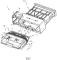
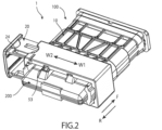
- FIGS. 1 to 3 are perspective views of a connector assembly as an embodiment according to the present invention.
- FIG. 1 illustrates a first connector 100 and a second connector 200 before mating.
- FIG. 2 illustrates a half-mating state.
- FIG. 3 illustrates a mating-completion state.
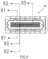
- FIG. 4 is a rear view of the first connector.
- FIG. 5 is a cross sectional view in the half-mating state illustrated in FIG. 2 along Arrows X1-X1 illustrated in FIG. 4 .
- FIG.6 is a cross sectional view in the mating-completion state illustrated in FIG. 3 along Arrows X2-X2 illustrated in FIG. 4 .
- FIG.7 is a cross sectional view in the mating-completion state illustrated in FIG. 3 along Arrows X3-X3 illustrated in FIG. 4 .
- the connector assembly 1 includes the first connector 100 and the second connector 200.
- the first connector 100 includes a housing 10 and a slider 20.
- the housing 10 has a first receiving space 11 to receive the second connector 200.
- the second connector 200 being inserted in a direction of Arrow F is received in the first receiving space 11.
- a lot of cables 30 are inserted from a rear side of the housing 10 in the housing 10 of the first connector 100.
- terminals 31 are connected by crimping to core wires of the cables 30.
- each of the cables 30 is surrounded by a waterproof member 32 (see FIG. 6 and FIG. 7 ), to prevent water from entering an inside of the housing.
- the slider 20 of the first connector 100 is held by the housing 10 such that the slider 20 is to be slidable in a width direction indicated by Arrows W1-W2 which direction intersects a mating direction (a direction indicated by Arrow F illustrated in FIG. 1 ).
- the slider 20 is formed in an approximate U-shape, to form a second receiving space 21 in the first receiving space 11 formed in the housing 10.
- the slider 20 includes cam grooves 22. As illustrated in FIG. 1 , two cam grooves 22 are provided in a lower face of an inner wall of the slider 22. In addition, similarly to this, two similar cam grooves are also provided in an upper face of the inner wall of the slider 20.
- the slider 20 includes first locking sections 23 and second locking sections 24.
- the first locking sections 23 are arranged one by one in a top and a bottom of the slider 20, extend in a cantilever form in a direction of Arrow W1, and respectively include protrusions on tips which protrusions protrude in an inside of the second receiving space 21.
- the two, top and bottom, first locking sections 23 lock with the housing 10 in the before-mating state, to prevent the slider 20 from easily coming out the housing 10.
- the second locking sections 24 are also arranged one by one in the top and the bottom of the slider 20.
- top and bottom locking sections 24 extend in a cantilever form in a direction of Arrow W2 opposite to that of the first locking sections 23, and include protrusions on tips thereof which protrusions protrude outward.
- the two, top and bottom, locking sections 24 lock with the housing 10 when being in the mating-completion state illustrated in FIG. 3 , playing a role of maintaining the mating-completion sate.
- first protrusions 25 are formed on the inner wall of the slider 20.
- the first protrusions 25 are provided one by one on the upper face and the lower face of the inner wall of the slider 20, to protrude in the inside of the second receiving space 21.
- the upper and lower protrusions 25 are provided at locations different from each other with respect to the width direction indicated by Arrows W1-W2. Details will be described later.
- the second connector 200 has an edge section along a side of a circuit board 210 exposed in a tip section thereof on a side of the first connector 100. And, the second connector 200 has configurations in which the whole thereof except for the exposed edge section of the circuit board 210 is covered with resin 50 together with circuit components (not illustrated) mounted on the circuit board 210.
- Connecting pads 211 formed by printed wirings are arranged on the exposed edge section of the circuit board 210. These connecting pads 211 are male terminals to electrically connect to the terminals 31 (see FIG. 6 and FIG. 7 ) connected by crimping to tips of the cables 30 of the first connector 100.
- the terminals 31 are pressed toward the circuit board 210 by a spacer 40 which is movably accommodated in the housing 10, to contact the connecting pads 211.
- the spacer 40 is pressed by the second connector 200 moving in the mating direction by an operation of the slider 20, to move leftward in FIG. 6 so as to press the terminals 31.
- depressed sections 51 are formed two by two on a top and a bottom in a tip portion covered by the resin 50 of the second connector 200.
- the depression sections 51 play a role of temporary locking in the half-mating state.
- the spacer 40 of the first connector 100 respectively includes on tips thereof third locking sections 41 respectively including protrusions protruding inward in a cantilever form in a direction indicated by Arrow R illustrated in FIG. 1 .
- the protrusions on the tips of the third locking sections 41 enter the depression sections 51 of the second connector 200, thereby making a temporary locking state.
- a waterproof member 220 circumferentially surrounding the resin 50 is arranged slightly more rearward than the depression sections 51 on the second connector 200.
- two bosses 52 protruding outward from an upper face of an outer wall thereof are provided.
- two bosses 52 are also provided on a lower face, in addition to the upper face, of the outer wall of the second connector 200. The two bosses 52 provided on the lower face of the outer wall of the second connector 200 enter the two cam grooves 22 provided in the lower face of the inner wall of the slider 20, respectively.
- the two bosses 52 provided on the upper face of the outer wall of the second connector 200 enter the two cam grooves 22 provided in the upper face of the inner wall of the slider 20, respectively (see FIG. 6 and FIG. 7 ).
- each of the bosses 52 is caused to enter each of the cam grooves 22 to slide the slider 20 in a first direction indicated by Arrow W1.
- the second connector 200 is drawn into the inside of the first connector 100 in accordance with the shape of the cam grooves 22 as illustrated in FIG. 2 and further in FIG. 3 .
- the second connector 200 is pressed out in the direction of Arrow R, a direction opposite to the mating direction indicated by Arrow F.
- a second protrusion 53 is formed to protrude outward at a location adjacent to a boss 52a on the left side of the two bosses 52 on the upper face of the outer wall illustrated in FIG. 1 .
- Another second protrusion 53 is also provided on the lower face of the outer wall of the second connector 200, in addition to the upper face of the outer wall.
- the second protrusion 53 which is provided on the lower face of the outer wall is not provided right under the second protrusions 53 on the upper face of the outer wall.
- the second connector 200 is inverted vertically to be in an up-side-down posture from the posture illustrated in FIG. 1 .
- the second protrusion 53 provided on the lower face of the outer wall is arranged at a location in which, when being in the up-side-down posture, the second protrusion 53 of the lower face of the outer wall comes to a same location where the second protrusion 53 of the upper face of the outer wall illustrated in FIG. 1 is located.
- the second protrusion 53 on the lower face of the outer wall is provided at a location adjacent to a boss 52b on the right side at whose adjacent position the second protrusion 53 is not provided in FIG. 1 .
- the second protrusion provided on the lower face of the outer wall of the second connector 200 is provided at a location to go up onto the first protrusion 25 provided on the lower face of the inner wall of the slider 20 in the mating-completion state illustrated in FIG. 3 .
- the first protrusion is also provided on the upper face of the inner wall of the slider 20.
- the first protrusion on the upper face of the inner wall is provided at a location to vertically overlap the second protrusion 53 provided on the upper face of the inner wall of the second connector 200 in the mating-completion state illustrated in FIG. 3 .
- the first protrusions 25 provided on the slider 20 will be pressed by the second protrusions 53 provided on the second connector 200 to expand the second receiving space 21 vertically.
- FIG. 6 illustrates a state in which the first protrusion 25 provided on the lower face of the inner wall of the slider 20 and the second protrusion 53 provided on the lower face of the outer wall of the second connector 200 vertically overlap each other. Since the locations at which the first protrusions 25 are provided and the locations at which the second protrusions 53 are provided are different from each other between the upper face and the lower face, the first protrusion 25 and the second protrusion 53 on the upper face side are not illustrated in FIG. 6 .
- the second connector 200 is held by the slider 20 also at locations remote from the locations where the first protrusions 25 and the second protrusions 53 overlap each other, for example, at locations near the waterproof member 200. These configurations also contribute to restraining backlash between the second connector 200 and slider 20.
- FIG. 7 illustrates a state in which positions of cross sections are changed between in the upper half and in the lower half, and thus the first protrusions 25 and the second protrusions 53 respectively overlap each other both on the upper side and on the lower side.
- the first protrusions 22 provided on the slider 20 are pressed by the second protrusions 53 provided on the second connector 200, so that the upper wall of the slider 20 is pressed upward and the lower wall of the slider 20 is pressed downward.
- the outer walls of the slider 20 are caused to abut against the faces of the inner wall of the housing 10.
- the backlash restraining configurations to restrain backlash between the first connector 100 and the second connector 200 are obtained.
- a connector of the card edge connector type as the second connector 200 is described herein.
- the present invention does not necessarily include a connector of the card edge connector type, and may be widely applied to connector assemblies using sliders.
Landscapes
- Details Of Connecting Devices For Male And Female Coupling (AREA)
- Coupling Device And Connection With Printed Circuit (AREA)
Claims (3)
- Verbinderanordnung, die einen ersten Verbinder (100) und einen zweiten Verbinder (200) umfasst, die zum Verpaaren miteinander konfiguriert sind, wobei
der erste Verbinder (100) Folgendes beinhaltet:ein Gehäuse (10) mit einem ersten Aufnahmeraum (11) zur Aufnahme des zweiten Verbinders (200),einen Schieber (20), der im ersten Aufnahmeraum einen zweiten Aufnahmeraum (21) zur Aufnahme des zweiten Verbinders (200) bildet, von dem Gehäuse (10) so gehalten wird, dass der Schieber in einer eine Verpaarungsrichtung (F) schneidenden Richtung verschiebbar ist, in einer ersten Richtung gleitet, um zu bewirken, dass sich der zweite Verbinder (200) in der Verpaarungsrichtung (F) bewegt, in der der erste Verbinder (100) mit dem zweiten Verbinder ( 200) verpaart wird, und in einer zweiten Richtung entgegengesetzt zur ersten Richtung gleitet, um zu bewirken, dass sich der zweite Verbinder (200) in einer Richtung entgegengesetzt zur Verpaarungsrichtung (F) bewegt,wobei die Verbinderanordnung an einer Innenwand des Schiebers (20) und einer Außenwand des zweiten Verbinders (200) Spielbegrenzungskonfigurationen (25, 53) umfasst, die zum Zeitpunkt des Abschlusses des Verpaarungsvorgangs aneinander anstoßen, um Spiel zwischen dem ersten Verbinder (100) und dem zweiten Verbinder (200) zu begrenzen, dadurch gekennzeichnet, dass die Spielbegrenzungskonfigurationen Folgendes umfassen:einen ersten Vorsprung (25), der so an der Innenwand des Schiebers (20) vorgesehen ist, dass er in eine Innenseite des zweiten Aufnahmeraums vorsteht, undeinen zweiten Vorsprung (53), der so an der Außenwand des zweiten Verbinders (200) vorgesehen ist, dass er nach außen vorsteht, und zum Zeitpunkt des Abschlusses des Verpaarungsvorgangs den ersten Vorsprung (25) in eine Richtung drückt, um den zweiten Aufnahmeraum (21) zu erweitern, so dass der Schieber (20) an einer Innenwand des Gehäuses (10) anliegt. - Verbinderanordnung nach Anspruch 1, wobeider zweite Verbinder (200) einen Stecker mit einer Form eines auf einer Leiterplatte (210) ausgebildeten Anschlusspads (211) umfasst, undder erste Verbinder (100) ein Kartenrandverbinder zum Aufnehmen eines Rands der Leiterplatte (210) ist.
- Verbinderanordnung nach Anspruch 1, die einen Abstandshalter (40) umfasst, der beweglich in dem Gehäuse (10) untergebracht ist und an seinen Spitzen Verriegelungsabschnitte (41) mit Vorsprüngen aufweist, die in einer Auslegerform in einer der Verpaarungsrichtung (F) entgegengesetzten Richtung (R) nach innen vorstehen, wobei der zweite Verbinder (200) vertiefte Abschnitte (51) aufweist, die paarweise an einer Oberseite und einer Unterseite in einem durch ein Harz (50) bedeckten Spitzenabschnitt ausgebildet sind und die Vorsprünge an den Spitzen der Verriegelungsabschnitte (41) in die jeweiligen vertieften Abschnitte (51) eindringen, um einen vorübergehenden Verriegelungszustand herzustellen.
Applications Claiming Priority (2)
| Application Number | Priority Date | Filing Date | Title |
|---|---|---|---|
| JP2016190603 | 2016-09-29 | ||
| PCT/JP2017/034110 WO2018061981A1 (ja) | 2016-09-29 | 2017-09-21 | コネクタ組立体 |
Publications (3)
| Publication Number | Publication Date |
|---|---|
| EP3522308A1 EP3522308A1 (de) | 2019-08-07 |
| EP3522308A4 EP3522308A4 (de) | 2020-05-06 |
| EP3522308B1 true EP3522308B1 (de) | 2025-03-19 |
Family
ID=61760471
Family Applications (1)
| Application Number | Title | Priority Date | Filing Date |
|---|---|---|---|
| EP17855935.7A Active EP3522308B1 (de) | 2016-09-29 | 2017-09-21 | Verbinderbaugruppe |
Country Status (6)
| Country | Link |
|---|---|
| US (1) | US10608375B2 (de) |
| EP (1) | EP3522308B1 (de) |
| JP (1) | JP6874015B2 (de) |
| CN (1) | CN109792122B (de) |
| MY (1) | MY195453A (de) |
| WO (1) | WO2018061981A1 (de) |
Families Citing this family (3)
| Publication number | Priority date | Publication date | Assignee | Title |
|---|---|---|---|---|
| JP6874015B2 (ja) * | 2016-09-29 | 2021-05-19 | タイコエレクトロニクスジャパン合同会社 | コネクタ組立体 |
| DE102020114197B3 (de) * | 2020-05-27 | 2021-08-05 | REVONEER GmbH | Schutzgehäuse für elektrische Stecker |
| JP7462523B2 (ja) * | 2020-09-16 | 2024-04-05 | 日本航空電子工業株式会社 | レバー式コネクタ |
Citations (1)
| Publication number | Priority date | Publication date | Assignee | Title |
|---|---|---|---|---|
| US5575676A (en) * | 1994-02-25 | 1996-11-19 | The Whitaker Corporation | Cam-equipped connector |
Family Cites Families (16)
| Publication number | Priority date | Publication date | Assignee | Title |
|---|---|---|---|---|
| JP2001525106A (ja) * | 1997-04-15 | 2001-12-04 | ザ ウィタカー コーポレーション | 2次ロック機構及び嵌合機構付きコネクタ |
| JP3529021B2 (ja) | 1998-01-22 | 2004-05-24 | 矢崎総業株式会社 | 低挿入力コネクタ |
| US6142826A (en) * | 1998-03-13 | 2000-11-07 | The Whitaker Corporation | Sealed electrical connector with secondary locking member |
| US6155850A (en) * | 1998-09-25 | 2000-12-05 | The Whitaker Corporation | Cam slide electrical connector |
| EP1100160B1 (de) * | 1999-11-10 | 2007-03-21 | Molex Incorporated | Elektrischer Steckerzusammenbau mit verbessertem Nockensystem |
| JP3396193B2 (ja) * | 1999-11-10 | 2003-04-14 | 日本圧着端子製造株式会社 | ソケットコネクタ |
| JP2004193014A (ja) * | 2002-12-12 | 2004-07-08 | Sumitomo Wiring Syst Ltd | コネクタ |
| DE10357194B4 (de) * | 2002-12-12 | 2010-04-15 | Sumitomo Wiring Systems, Ltd., Yokkaichi | Verbinderanordnung |
| FR2864355A1 (fr) * | 2003-12-19 | 2005-06-24 | Framatome Connectors Int | Dispositif de verrouillage d'un module de connecteur dans un porte-module |
| US7347704B2 (en) * | 2006-03-01 | 2008-03-25 | Sumitomo Wiring Systems, Ltd. | Connector |
| CN102341968B (zh) * | 2008-12-31 | 2013-11-20 | 富加宜汽车控股公司 | 具有配合辅助设备的连接器装置 |
| JP5679552B2 (ja) | 2010-10-18 | 2015-03-04 | 矢崎総業株式会社 | レバー式コネクタ |
| JP5533893B2 (ja) * | 2012-01-07 | 2014-06-25 | 株式会社デンソー | 電子装置 |
| JP5987795B2 (ja) * | 2013-07-16 | 2016-09-07 | 住友電装株式会社 | コネクタ |
| DE102013225512B4 (de) * | 2013-12-10 | 2022-02-03 | Te Connectivity Germany Gmbh | Steckverbinder mit Verriegelungshebel |
| JP6874015B2 (ja) * | 2016-09-29 | 2021-05-19 | タイコエレクトロニクスジャパン合同会社 | コネクタ組立体 |
-
2017
- 2017-09-21 JP JP2018542486A patent/JP6874015B2/ja active Active
- 2017-09-21 WO PCT/JP2017/034110 patent/WO2018061981A1/ja not_active Ceased
- 2017-09-21 EP EP17855935.7A patent/EP3522308B1/de active Active
- 2017-09-21 CN CN201780060613.6A patent/CN109792122B/zh active Active
- 2017-09-21 MY MYPI2019001005A patent/MY195453A/en unknown
-
2019
- 2019-03-20 US US16/359,241 patent/US10608375B2/en active Active
Patent Citations (1)
| Publication number | Priority date | Publication date | Assignee | Title |
|---|---|---|---|---|
| US5575676A (en) * | 1994-02-25 | 1996-11-19 | The Whitaker Corporation | Cam-equipped connector |
Also Published As
| Publication number | Publication date |
|---|---|
| JP6874015B2 (ja) | 2021-05-19 |
| MY195453A (en) | 2023-01-24 |
| US20190214768A1 (en) | 2019-07-11 |
| US10608375B2 (en) | 2020-03-31 |
| CN109792122A (zh) | 2019-05-21 |
| EP3522308A1 (de) | 2019-08-07 |
| JPWO2018061981A1 (ja) | 2019-07-04 |
| EP3522308A4 (de) | 2020-05-06 |
| BR112019005462A2 (pt) | 2019-06-04 |
| WO2018061981A1 (ja) | 2018-04-05 |
| CN109792122B (zh) | 2021-06-04 |
Similar Documents
| Publication | Publication Date | Title |
|---|---|---|
| JP4267935B2 (ja) | 電気コネクタ組立体及び電気コネクタ | |
| US20200358226A1 (en) | Compact electrical connector | |
| EP2369691B1 (de) | Hebelsteckverbinder | |
| JP6422908B2 (ja) | コネクタ | |
| CN102386525B (zh) | 杠杆型连接器 | |
| EP2850698B1 (de) | Verbinder für leiterplatten | |
| EP3522308B1 (de) | Verbinderbaugruppe | |
| JP2007305537A (ja) | コネクタ | |
| CN202196895U (zh) | 电连接器及电连接器组件 | |
| KR20130135317A (ko) | 충돌식 커넥터 | |
| JP5076947B2 (ja) | コネクタ装置 | |
| US20180026390A1 (en) | Connector | |
| EP4343979A1 (de) | Aussengehäuse für steckverbinder | |
| CN111525353A (zh) | 电连接器 | |
| KR20140019244A (ko) | 박형 와이어 투 보드 커넥터용 래칭 장치 | |
| KR100952811B1 (ko) | 차폐용 커넥터 및 이를 구비한 차폐용 커넥터 세트 | |
| KR200496183Y1 (ko) | 자기 잠금식 커넥터 | |
| KR102242005B1 (ko) | 락킹 usb 젠더 | |
| JP2023170503A (ja) | Cpa取付け構造、cpa付きコネクタ、及びワイヤーハーネス | |
| JP5767870B2 (ja) | レバー式コネクタ | |
| JP3226008U (ja) | バックルコネクタ | |
| CN220985028U (zh) | 锁止件、内壳体、板端和线端连接器、转接线及连接组件 | |
| CN223402019U (zh) | 电连接器组合 | |
| JP2017506410A (ja) | 多機能コネクタ位置決め保証デバイス | |
| KR20240157193A (ko) | 커넥터 어셈블리 |
Legal Events
| Date | Code | Title | Description |
|---|---|---|---|
| STAA | Information on the status of an ep patent application or granted ep patent |
Free format text: STATUS: THE INTERNATIONAL PUBLICATION HAS BEEN MADE |
|
| PUAI | Public reference made under article 153(3) epc to a published international application that has entered the european phase |
Free format text: ORIGINAL CODE: 0009012 |
|
| STAA | Information on the status of an ep patent application or granted ep patent |
Free format text: STATUS: REQUEST FOR EXAMINATION WAS MADE |
|
| 17P | Request for examination filed |
Effective date: 20190204 |
|
| AK | Designated contracting states |
Kind code of ref document: A1 Designated state(s): AL AT BE BG CH CY CZ DE DK EE ES FI FR GB GR HR HU IE IS IT LI LT LU LV MC MK MT NL NO PL PT RO RS SE SI SK SM TR |
|
| AX | Request for extension of the european patent |
Extension state: BA ME |
|
| DAV | Request for validation of the european patent (deleted) | ||
| DAX | Request for extension of the european patent (deleted) | ||
| A4 | Supplementary search report drawn up and despatched |
Effective date: 20200407 |
|
| RIC1 | Information provided on ipc code assigned before grant |
Ipc: H01R 13/629 20060101AFI20200401BHEP |
|
| STAA | Information on the status of an ep patent application or granted ep patent |
Free format text: STATUS: EXAMINATION IS IN PROGRESS |
|
| 17Q | First examination report despatched |
Effective date: 20210806 |
|
| GRAP | Despatch of communication of intention to grant a patent |
Free format text: ORIGINAL CODE: EPIDOSNIGR1 |
|
| STAA | Information on the status of an ep patent application or granted ep patent |
Free format text: STATUS: GRANT OF PATENT IS INTENDED |
|
| INTG | Intention to grant announced |
Effective date: 20241011 |
|
| GRAS | Grant fee paid |
Free format text: ORIGINAL CODE: EPIDOSNIGR3 |
|
| GRAA | (expected) grant |
Free format text: ORIGINAL CODE: 0009210 |
|
| STAA | Information on the status of an ep patent application or granted ep patent |
Free format text: STATUS: THE PATENT HAS BEEN GRANTED |
|
| AK | Designated contracting states |
Kind code of ref document: B1 Designated state(s): AL AT BE BG CH CY CZ DE DK EE ES FI FR GB GR HR HU IE IS IT LI LT LU LV MC MK MT NL NO PL PT RO RS SE SI SK SM TR |
|
| REG | Reference to a national code |
Ref country code: GB Ref legal event code: FG4D |
|
| REG | Reference to a national code |
Ref country code: CH Ref legal event code: EP |
|
| REG | Reference to a national code |
Ref country code: IE Ref legal event code: FG4D |
|
| REG | Reference to a national code |
Ref country code: DE Ref legal event code: R096 Ref document number: 602017088448 Country of ref document: DE |
|
| PG25 | Lapsed in a contracting state [announced via postgrant information from national office to epo] |
Ref country code: RS Free format text: LAPSE BECAUSE OF FAILURE TO SUBMIT A TRANSLATION OF THE DESCRIPTION OR TO PAY THE FEE WITHIN THE PRESCRIBED TIME-LIMIT Effective date: 20250619 |
|
| PG25 | Lapsed in a contracting state [announced via postgrant information from national office to epo] |
Ref country code: FI Free format text: LAPSE BECAUSE OF FAILURE TO SUBMIT A TRANSLATION OF THE DESCRIPTION OR TO PAY THE FEE WITHIN THE PRESCRIBED TIME-LIMIT Effective date: 20250319 |
|
| REG | Reference to a national code |
Ref country code: LT Ref legal event code: MG9D |
|
| PG25 | Lapsed in a contracting state [announced via postgrant information from national office to epo] |
Ref country code: NO Free format text: LAPSE BECAUSE OF FAILURE TO SUBMIT A TRANSLATION OF THE DESCRIPTION OR TO PAY THE FEE WITHIN THE PRESCRIBED TIME-LIMIT Effective date: 20250619 |
|
| PGFP | Annual fee paid to national office [announced via postgrant information from national office to epo] |
Ref country code: IT Payment date: 20250522 Year of fee payment: 9 |
|
| PG25 | Lapsed in a contracting state [announced via postgrant information from national office to epo] |
Ref country code: HR Free format text: LAPSE BECAUSE OF FAILURE TO SUBMIT A TRANSLATION OF THE DESCRIPTION OR TO PAY THE FEE WITHIN THE PRESCRIBED TIME-LIMIT Effective date: 20250319 |
|
| PG25 | Lapsed in a contracting state [announced via postgrant information from national office to epo] |
Ref country code: LV Free format text: LAPSE BECAUSE OF FAILURE TO SUBMIT A TRANSLATION OF THE DESCRIPTION OR TO PAY THE FEE WITHIN THE PRESCRIBED TIME-LIMIT Effective date: 20250319 |
|
| PG25 | Lapsed in a contracting state [announced via postgrant information from national office to epo] |
Ref country code: GR Free format text: LAPSE BECAUSE OF FAILURE TO SUBMIT A TRANSLATION OF THE DESCRIPTION OR TO PAY THE FEE WITHIN THE PRESCRIBED TIME-LIMIT Effective date: 20250620 Ref country code: BG Free format text: LAPSE BECAUSE OF FAILURE TO SUBMIT A TRANSLATION OF THE DESCRIPTION OR TO PAY THE FEE WITHIN THE PRESCRIBED TIME-LIMIT Effective date: 20250319 |
|
| RAP4 | Party data changed (patent owner data changed or rights of a patent transferred) |
Owner name: TYCO ELECTRONICS JAPAN G.K. Owner name: HONDA MOTOR CO., LTD. |
|
| REG | Reference to a national code |
Ref country code: NL Ref legal event code: MP Effective date: 20250319 |
|
| REG | Reference to a national code |
Ref country code: AT Ref legal event code: MK05 Ref document number: 1777770 Country of ref document: AT Kind code of ref document: T Effective date: 20250319 |
|
| PG25 | Lapsed in a contracting state [announced via postgrant information from national office to epo] |
Ref country code: NL Free format text: LAPSE BECAUSE OF FAILURE TO SUBMIT A TRANSLATION OF THE DESCRIPTION OR TO PAY THE FEE WITHIN THE PRESCRIBED TIME-LIMIT Effective date: 20250319 |
|
| PG25 | Lapsed in a contracting state [announced via postgrant information from national office to epo] |
Ref country code: SE Free format text: LAPSE BECAUSE OF FAILURE TO SUBMIT A TRANSLATION OF THE DESCRIPTION OR TO PAY THE FEE WITHIN THE PRESCRIBED TIME-LIMIT Effective date: 20250319 |
|
| RAP4 | Party data changed (patent owner data changed or rights of a patent transferred) |
Owner name: TE CONNECTIVITY JAPAN G.K. Owner name: HONDA MOTOR CO., LTD. |
|
| PG25 | Lapsed in a contracting state [announced via postgrant information from national office to epo] |
Ref country code: SM Free format text: LAPSE BECAUSE OF FAILURE TO SUBMIT A TRANSLATION OF THE DESCRIPTION OR TO PAY THE FEE WITHIN THE PRESCRIBED TIME-LIMIT Effective date: 20250319 |
|
| PG25 | Lapsed in a contracting state [announced via postgrant information from national office to epo] |
Ref country code: PT Free format text: LAPSE BECAUSE OF FAILURE TO SUBMIT A TRANSLATION OF THE DESCRIPTION OR TO PAY THE FEE WITHIN THE PRESCRIBED TIME-LIMIT Effective date: 20250721 Ref country code: ES Free format text: LAPSE BECAUSE OF FAILURE TO SUBMIT A TRANSLATION OF THE DESCRIPTION OR TO PAY THE FEE WITHIN THE PRESCRIBED TIME-LIMIT Effective date: 20250319 |
|
| PGFP | Annual fee paid to national office [announced via postgrant information from national office to epo] |
Ref country code: DE Payment date: 20250522 Year of fee payment: 9 |
|
| PG25 | Lapsed in a contracting state [announced via postgrant information from national office to epo] |
Ref country code: PL Free format text: LAPSE BECAUSE OF FAILURE TO SUBMIT A TRANSLATION OF THE DESCRIPTION OR TO PAY THE FEE WITHIN THE PRESCRIBED TIME-LIMIT Effective date: 20250319 |
|
| PG25 | Lapsed in a contracting state [announced via postgrant information from national office to epo] |
Ref country code: AT Free format text: LAPSE BECAUSE OF FAILURE TO SUBMIT A TRANSLATION OF THE DESCRIPTION OR TO PAY THE FEE WITHIN THE PRESCRIBED TIME-LIMIT Effective date: 20250319 |
|
| PG25 | Lapsed in a contracting state [announced via postgrant information from national office to epo] |
Ref country code: EE Free format text: LAPSE BECAUSE OF FAILURE TO SUBMIT A TRANSLATION OF THE DESCRIPTION OR TO PAY THE FEE WITHIN THE PRESCRIBED TIME-LIMIT Effective date: 20250319 Ref country code: CZ Free format text: LAPSE BECAUSE OF FAILURE TO SUBMIT A TRANSLATION OF THE DESCRIPTION OR TO PAY THE FEE WITHIN THE PRESCRIBED TIME-LIMIT Effective date: 20250319 |
|
| PG25 | Lapsed in a contracting state [announced via postgrant information from national office to epo] |
Ref country code: RO Free format text: LAPSE BECAUSE OF FAILURE TO SUBMIT A TRANSLATION OF THE DESCRIPTION OR TO PAY THE FEE WITHIN THE PRESCRIBED TIME-LIMIT Effective date: 20250319 |
|
| PG25 | Lapsed in a contracting state [announced via postgrant information from national office to epo] |
Ref country code: SK Free format text: LAPSE BECAUSE OF FAILURE TO SUBMIT A TRANSLATION OF THE DESCRIPTION OR TO PAY THE FEE WITHIN THE PRESCRIBED TIME-LIMIT Effective date: 20250319 |
|
| PG25 | Lapsed in a contracting state [announced via postgrant information from national office to epo] |
Ref country code: IS Free format text: LAPSE BECAUSE OF FAILURE TO SUBMIT A TRANSLATION OF THE DESCRIPTION OR TO PAY THE FEE WITHIN THE PRESCRIBED TIME-LIMIT Effective date: 20250719 |
|
| REG | Reference to a national code |
Ref country code: DE Ref legal event code: R097 Ref document number: 602017088448 Country of ref document: DE |
|
| PG25 | Lapsed in a contracting state [announced via postgrant information from national office to epo] |
Ref country code: DK Free format text: LAPSE BECAUSE OF FAILURE TO SUBMIT A TRANSLATION OF THE DESCRIPTION OR TO PAY THE FEE WITHIN THE PRESCRIBED TIME-LIMIT Effective date: 20250319 |
|
| PLBE | No opposition filed within time limit |
Free format text: ORIGINAL CODE: 0009261 |
|
| STAA | Information on the status of an ep patent application or granted ep patent |
Free format text: STATUS: NO OPPOSITION FILED WITHIN TIME LIMIT |
|
| REG | Reference to a national code |
Ref country code: CH Ref legal event code: L10 Free format text: ST27 STATUS EVENT CODE: U-0-0-L10-L00 (AS PROVIDED BY THE NATIONAL OFFICE) Effective date: 20260128 |
|
| 26N | No opposition filed |
Effective date: 20251222 |