EP3521801B1 - Test result evaluating method and a kit comprising a material tester and a hammer - Google Patents
Test result evaluating method and a kit comprising a material tester and a hammer Download PDFInfo
- Publication number
- EP3521801B1 EP3521801B1 EP18214260.4A EP18214260A EP3521801B1 EP 3521801 B1 EP3521801 B1 EP 3521801B1 EP 18214260 A EP18214260 A EP 18214260A EP 3521801 B1 EP3521801 B1 EP 3521801B1
- Authority
- EP
- European Patent Office
- Prior art keywords
- test
- main body
- data
- amplitude
- natural vibration
- Prior art date
- Legal status (The legal status is an assumption and is not a legal conclusion. Google has not performed a legal analysis and makes no representation as to the accuracy of the status listed.)
- Active
Links
Images

Classifications
-
- G—PHYSICS
- G01—MEASURING; TESTING
- G01N—INVESTIGATING OR ANALYSING MATERIALS BY DETERMINING THEIR CHEMICAL OR PHYSICAL PROPERTIES
- G01N3/00—Investigating strength properties of solid materials by application of mechanical stress
- G01N3/62—Manufacturing, calibrating, or repairing devices used in investigations covered by the preceding subgroups
-
- G—PHYSICS
- G01—MEASURING; TESTING
- G01L—MEASURING FORCE, STRESS, TORQUE, WORK, MECHANICAL POWER, MECHANICAL EFFICIENCY, OR FLUID PRESSURE
- G01L1/00—Measuring force or stress, in general
- G01L1/10—Measuring force or stress, in general by measuring variations of frequency of stressed vibrating elements, e.g. of stressed strings
- G01L1/103—Measuring force or stress, in general by measuring variations of frequency of stressed vibrating elements, e.g. of stressed strings optical excitation or measuring of vibrations
-
- G—PHYSICS
- G01—MEASURING; TESTING
- G01N—INVESTIGATING OR ANALYSING MATERIALS BY DETERMINING THEIR CHEMICAL OR PHYSICAL PROPERTIES
- G01N29/00—Investigating or analysing materials by the use of ultrasonic, sonic or infrasonic waves; Visualisation of the interior of objects by transmitting ultrasonic or sonic waves through the object
- G01N29/04—Analysing solids
- G01N29/12—Analysing solids by measuring frequency or resonance of acoustic waves
-
- G—PHYSICS
- G01—MEASURING; TESTING
- G01N—INVESTIGATING OR ANALYSING MATERIALS BY DETERMINING THEIR CHEMICAL OR PHYSICAL PROPERTIES
- G01N3/00—Investigating strength properties of solid materials by application of mechanical stress
- G01N3/08—Investigating strength properties of solid materials by application of mechanical stress by applying steady tensile or compressive forces
-
- G—PHYSICS
- G01—MEASURING; TESTING
- G01N—INVESTIGATING OR ANALYSING MATERIALS BY DETERMINING THEIR CHEMICAL OR PHYSICAL PROPERTIES
- G01N3/00—Investigating strength properties of solid materials by application of mechanical stress
- G01N3/30—Investigating strength properties of solid materials by application of mechanical stress by applying a single impulsive force, e.g. by falling weight
-
- G—PHYSICS
- G01—MEASURING; TESTING
- G01N—INVESTIGATING OR ANALYSING MATERIALS BY DETERMINING THEIR CHEMICAL OR PHYSICAL PROPERTIES
- G01N2203/00—Investigating strength properties of solid materials by application of mechanical stress
- G01N2203/0001—Type of application of the stress
- G01N2203/0003—Steady
-
- G—PHYSICS
- G01—MEASURING; TESTING
- G01N—INVESTIGATING OR ANALYSING MATERIALS BY DETERMINING THEIR CHEMICAL OR PHYSICAL PROPERTIES
- G01N2203/00—Investigating strength properties of solid materials by application of mechanical stress
- G01N2203/0001—Type of application of the stress
- G01N2203/001—Impulsive
-
- G—PHYSICS
- G01—MEASURING; TESTING
- G01N—INVESTIGATING OR ANALYSING MATERIALS BY DETERMINING THEIR CHEMICAL OR PHYSICAL PROPERTIES
- G01N2203/00—Investigating strength properties of solid materials by application of mechanical stress
- G01N2203/0001—Type of application of the stress
- G01N2203/0012—Constant speed test
-
- G—PHYSICS
- G01—MEASURING; TESTING
- G01N—INVESTIGATING OR ANALYSING MATERIALS BY DETERMINING THEIR CHEMICAL OR PHYSICAL PROPERTIES
- G01N2203/00—Investigating strength properties of solid materials by application of mechanical stress
- G01N2203/0014—Type of force applied
- G01N2203/0016—Tensile or compressive
- G01N2203/0017—Tensile
-
- G—PHYSICS
- G01—MEASURING; TESTING
- G01N—INVESTIGATING OR ANALYSING MATERIALS BY DETERMINING THEIR CHEMICAL OR PHYSICAL PROPERTIES
- G01N2203/00—Investigating strength properties of solid materials by application of mechanical stress
- G01N2203/02—Details not specific for a particular testing method
- G01N2203/0202—Control of the test
- G01N2203/021—Treatment of the signal; Calibration
-
- G—PHYSICS
- G01—MEASURING; TESTING
- G01N—INVESTIGATING OR ANALYSING MATERIALS BY DETERMINING THEIR CHEMICAL OR PHYSICAL PROPERTIES
- G01N2203/00—Investigating strength properties of solid materials by application of mechanical stress
- G01N2203/02—Details not specific for a particular testing method
- G01N2203/0202—Control of the test
- G01N2203/0212—Theories, calculations
- G01N2203/0218—Calculations based on experimental data
-
- G—PHYSICS
- G01—MEASURING; TESTING
- G01N—INVESTIGATING OR ANALYSING MATERIALS BY DETERMINING THEIR CHEMICAL OR PHYSICAL PROPERTIES
- G01N2203/00—Investigating strength properties of solid materials by application of mechanical stress
- G01N2203/02—Details not specific for a particular testing method
- G01N2203/025—Geometry of the test
- G01N2203/0252—Monoaxial, i.e. the forces being applied along a single axis of the specimen
-
- G—PHYSICS
- G01—MEASURING; TESTING
- G01N—INVESTIGATING OR ANALYSING MATERIALS BY DETERMINING THEIR CHEMICAL OR PHYSICAL PROPERTIES
- G01N2203/00—Investigating strength properties of solid materials by application of mechanical stress
- G01N2203/02—Details not specific for a particular testing method
- G01N2203/026—Specifications of the specimen
- G01N2203/0262—Shape of the specimen
- G01N2203/0268—Dumb-bell specimens
Definitions
- the disclosure relates to a test result evaluating method for evaluating the reliability of a test result in a material test applying a test force to a test subject and a material tester.
- a material tester executing a material test includes a load mechanism that applies a test force to a test piece that is a testing target and a force detector that is used for detecting a force applied to the test piece in the execution thereof (see Patent Documents 1 and 2).
- Methods for tensile testing of plastic materials is discussed in XIAO et al., "Dynamic tensile testing of plastic materials", POLYMER TESTING, ELSEVIER, AMSTERDAM, NL, (2007/11/05), vol. 27, no. 2, doi: 10. 10 1 6/J.POLYMERTES TING. 2007.09.
- a high-speed tension test or a punching test there are cases in which an impact of breakage or destruction of a test piece reaches the whole tester (a system including a jig and a force detector), and an amplitude according to a natural vibration of a defective tester main body is superimposed on a waveform of test data based on detection performed by the force detector.
- the waveform represents a force that is actually applied to the test piece, and thus the reliability of a test result is degraded.
- Fig. 9 is a test force - time graph illustrating a technique for determining the amplitude of a natural vibration superimposed on data between a test starting point and a breaking point from test data of a conventional high-speed tension test.
- the vertical axis represents a test force (kilonewtons (KN))
- the horizontal axis represents time (milliseconds (ms)).
- test data determined by a force detector is collected for a predetermined time period including before and after a time at which a test force is actually applied to a test piece. As illustrated in Fig.
- test data detected by the force detector can be divided into three data periods A, B, and C including A: before a starting point of a test at which a test force starts to be applied to a test piece, B: between the starting point of the test and a breaking point at which the test piece breaks in a state in which a test force is applied to the test piece, and C: after the breaking point of the test piece.
- a data period used for evaluating material characteristics is the data period B.
- the user extracts raw data stored in a storage device of a material tester which is a result of the test, prints a test force - time graph as illustrated in Fig.
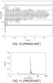
- Fig. 10 is a graph illustrating the amplitude of a natural vibration and the amplitude of test data between a test starting point to a breaking point of a high-speed tension test that are acquired through a Fourier transform and illustrates a time axis of a data period in which there is a state in which a test force is being applied to a test piece (the data period B illustrated in Fig. 9 ) in an enlarged scale.
- Fig. 11 is a graph acquired by performing a Fourier transform on the waveform of the test force illustrated in Fig. 10 . In the graph represented in Fig.
- the vertical axis represents a test force (kilonewtons (kN)), and the horizontal axis represents a time (milliseconds (ms)).
- the vertical axis represents an amplitude
- the horizontal axis represents a frequency (kilohertz (kHz)).
- a frequency spectrum illustrated in Fig. 11 is acquired.
- the amplitude at a frequency at which a maximum peak is formed is 0.34.
- a frequency at which a maximum peak value is formed through a Fourier transform is set as a natural vibration frequency, and an amplitude of a test force at this time is set as the amplitude of the natural vibration.
- the disclosure has been realized for solving the problems described above, and an objective thereof is to provide an amplitude detecting method and a material tester capable of quantitatively acquiring the amplitude of a natural vibration superimposed on test data.
- a disclosure according to a first aspect of the disclosure is an amplitude detecting method, according to claim 1 herein, of detecting an amplitude of a natural vibration superimposed on test data based on a signal detected by a force detector in a material test applying a test force to a test subject by driving a load mechanism.
- a disclosure according to a second aspect of the disclosure is a kit comprising a material tester and a hammer according to claim 5 herein.
- information used for objectively evaluating the reliability of a test can be provided for a user.
- amplitude detection using the frequency of the natural vibration can be executed without checking a vibration frequency of the natural vibration of a system including the force detector of the tester main body and the jig using another vibration detecting device in advance.
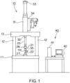
- Fig. 1 is a diagram illustrating an overview of a material tester according to the disclosure.
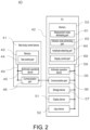
- Fig. 2 is a block diagram illustrating a main control system of the material tester according to the disclosure.
- This material tester executes a high-speed tension test of rapidly applying a shocking tensile force to a test piece TP and includes a tester main body 10 and a control device 40.
- the tester main body 10 includes a table 11, one pair of support posts 12 erected on the table 11, a cross yoke 13 stretched over the one pair of support posts 12, and a hydraulic cylinder 31 fixed to the cross yoke 13.
- the hydraulic cylinder 31 is connected to a hydraulic power source (not illustrated in the drawing) disposed inside the table 11 through a servo valve 34 and operates in accordance with a hydraulic oil supplied from the hydraulic power source.
- An upper chuck 21 is connected to a piston rod 32 of the hydraulic cylinder 31 through a run-up jig 25 and a joint 26.
- a lower chuck 22 is connected to the table 11 through a load cell 27 that is a force detector.
- the configuration of this tester main body 10 is a configuration for executing a tension test for rapidly separating one pair of chucks, which grip both end portions of the test piece TP, away from each other by disposing a run-up section in a pulling direction using the run-up jig 25 and lifting a piston rod 32 at a high speed of 0.1 to 20 m/s.
- a displacement (stroke) of a load mechanism at the time of execution of a tension test in other words, a moving amount of the piston rod 32 is detected by a stroke sensor 33, and a test force at that time is detected by the load cell 27.
- an extensometer 35 is disposed on the test piece TP.
- the extensometer 35 is directly attached to a test piece TP for measuring the expansion of the test piece TP and, for example, has a structure as disclosed in Japanese Unexamined Patent Application Publication No. 2006-10409 .
- fixing tools respectively fixed to marked lines at two positions set on the test piece TP, a pipe formed from a conductor fixed to one fixing tool, and a coil inserted into the inside of a pipe fixed to the other fixing tool to be movable are included, and a change in inductance of a coil based on a change in the amount of insertion of the coil with respect to the pipe is detected, and an expansion of the test piece TP between the marked lines is measured.
- a signal of the stroke sensor 33 may be used, or the displacement may be measured using a non-contact type extensometer such as a high-speed video camera.
- the control device 40 is composed of a main body control device 41 used for controlling the operation of the tester main body 10 and a personal computer 42.
- the main body control device 41 includes a memory 43 that stores a program, an arithmetic operation device 45 such as a micro processing unit (MPU) that executes various arithmetic operations, and a communication part 46 that communicates with the personal computer 42.
- the memory 43, the arithmetic operation device 45, and the communication part 46 are interconnected through a bus 49.
- the main body control device 41 includes a test control part 44 as a functional component.
- the test control part 44 is stored in the memory 43 as a test control program.
- a control signal is supplied to the servo valve 34, and the hydraulic cylinder 31 operates.
- Signal input/output parts respectively corresponding to the load cell 27, the stroke sensor 33, and the extensometer 35 are disposed in the main body control device 41, and an output signal of the load cell 27, an output signal of the stroke sensor 33, and an output signal of the extensometer 35 are digitalized and are taken in by the main body control device 41 over predetermined time intervals.
- the personal computer 42 includes a ROM that stores a data analysis program, a memory 53 formed by a RAM that loads a program and temporarily stores data at the time of execution of a program and the like, an arithmetic operation device 55 such as a central processing unit (CPU) executing various arithmetic operations, a communication part 56 that communicates with an externally-connected device such as the main body control device 41, a storage device 57 that stores data, a display device 51 on which a test result is displayed, and an input device 52 that is used for inputting test conditions.
- a program realizing a function by operating the arithmetic operation device 55 is stored in the memory 53.
- the storage device 57 is configured as a large-capacity storage device such as a hard disk drive (HDD) and stores time series data that is a raw data of a test force input from the load cell 27 and the like.
- the memory 53, the arithmetic operation device 55, the communication part 56, the storage device 57, the display device 51, and the input device 52 are interconnected through a bus 59.
- a measurement noise eliminating part 61 that eliminates measurement noise originating from a detector such as electrical fluctuation of detectors of the load cell 27 and the extensometer 35
- a vibration noise eliminating part 63 that eliminates vibration noise assumed to be caused by an inertial force according to natural vibration applied to the entire tester due to the impact of breakage or destruction of the test piece
- an amplitude detecting part 64 that detects the amplitude of a natural vibration superimposed in the data period used for evaluating material characteristics
- a display control part 69 that controls display of an amplitude value of the natural vibration and a test result on the display device 51 are provided as functional blocks.
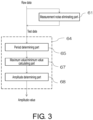
- Fig. 3 is a flowchart illustrating an amplitude detecting method according to a first embodiment
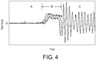
- Fig. 4 is a test force - time graph.
- the vertical axis represents a test force
- the horizontal axis represents a time.
- raw data which is acquired using the load cell 27, corresponding to a predetermined time period including before and after a time at which a test force is actually applied to the test piece TP is collected at a predetermined sampling rate and is stored in the storage device 57 as time series data.
- the test data used for amplitude detection may be data from which measurement noise has been eliminated by the measurement noise eliminating part 61.
- the measurement noise eliminating part 61 is configured as a noise cutoff filter causing a frequency of the measurement noise to disappear.
- the test data can be divided into data of three time periods of A: before a starting point of a test at which a test force is started to be applied to a test piece, B: between the starting point of the test and a breaking point at which the test piece breaks in a state in which a test force is applied to the test piece, and C: after the breaking point of the test piece (see Fig. 4 ).
- data that is mainly used for evaluating material characteristics is the data of the data period B, and thus, the amplitude detecting part 64 acquires the amplitude of a natural vibration superimposed on the test data of the data period B.
- the data period A can be used when a frequency of a measurement noise is acquired
- the data period C can be used for calculating vibration noise, in other words, a natural vibration frequency.
- the amplitude detecting part 64 includes a period determining part 65, a maximum value/minimum value calculating part 67, and an amplitude determining part 68.
- the amplitude detection in the data period B is realized by the arithmetic operation device 55 that reads programs from the period determining part 65, the maximum value/minimum value calculating part 67, and the amplitude determining part 68 of the amplitude detecting part 64 of the memory 53 and executes a period determining process, a maximum/minimum value calculating process, and an amplitude determining process.
- the period determining part 65 acquires one period of the waveform of a natural vibration from the reciprocal of the natural vibration frequency.
- a frequency of the natural vibration in a state in which a test is not executed, a frequency of the natural vibration acquired using another vibration detecting device not illustrated in the drawing by hitting the lower chuck 22 connected to the load cell 27 with a hammer or the like is stored in the storage device 57 in advance, and when the period determining process is executed, the frequency of the natural vibration is called from the storage device 57.
- a frequency of the natural vibration may be acquired by performing a Fourier transform using the data of the data period C (see Fig. 4 ) in which a large vibration according to an impact of breakage of a test piece TP appears.
- the maximum value/minimum value calculating part 67 calculates a maximum value and a minimum value in a time interval while moving the time interval on the data of the data period B over predetermined time intervals with reference to a time interval of one period of the waveform of the natural vibration.
- moving on the data of the data period B over predetermined time intervals represents that an operation of sliding a time interval on the data over an interval of five sampling points is repeated by assuming that there are 100 data points in the time interval of one period and an area for the calculation of a maximum value and a minimum value is moved with the time interval maintained.
- the maximum value and the minimum value acquired in this way are denoted by broken lines in Fig. 4 .
- the amplitude determining part 68 calculates a difference between the maximum value and the minimum value (the maximum value - the minimum value) denoted by the broken lines in Fig. 4 .
- a value of the difference between the maximum value and the minimum value corresponds to a wave height of the waveform of the vibration having a natural cycle that is superimposed on the test data of the data period B, and a value that is 1/2 of this value is the amplitude of the natural vibration.
- An amplitude value determined by the amplitude determining part 68 in this way is displayed in the display device 51 in accordance with an operation of the display control part 69 and is provided for a user as information.
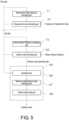
- FIG. 5 is a flowchart illustrating an amplitude detecting method according to a second embodiment
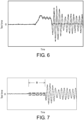
- Figs. 6 to 8 are test force - time graphs.
- the vertical axis represents a test force
- the horizontal axis represents a time.
- test data used for amplitude detection is measurement noise-eliminated data from which measurement noise has been eliminated by the measurement noise eliminating part 61
- a noise cutoff filter is configured on the basis of the frequency of the measurement noise.
- raw data from which measurement noise has not been eliminated may be directly used as test data.
- the frequency of measurement noise may be acquired by an operation of the measurement noise frequency calculating part 71 using the raw data of the data period A before starting of a test that is illustrated in Fig. 4 , or a frequency of measurement noise acquired using data collected for verification of the state of the load cell 27 before a test may be stored in the storage device 57 in advance and be read when a measurement noise eliminating process is executed by the measurement noise eliminating part 61.
- the measurement noise frequency calculating part 71 is a functional block representing a program executing a measurement noise frequency calculating process that is stored in the memory 53.
- the arithmetic operation device 55 executes a vibration noise eliminating process in which a program is read from the vibration noise eliminating part 63 of the memory 53, and vibration noise-eliminated data is acquired by eliminating the natural vibration from the test data.
- test data is denoted by a solid line
- vibration noise-eliminated data is denoted by a broken line.
- a natural vibration frequency acquired using the data period C in which a large vibration according to an impact of breakage of a test piece TP appears in the test data in accordance with an operation of the natural vibration frequency calculating part 73 may be used, or a natural vibration frequency acquired by another vibration detecting device not illustrated in the drawing by hitting the lower chuck 22 connected to the load cell 27 with a hammer or the like in a state in which a test is not executed may be stored in the storage device 57 in advance and be called from the storage device 57 when a vibration noise eliminating process is executed.
- the natural vibration frequency calculating part 73 is a functional block representing a program executing the natural vibration frequency calculating process stored in the memory 53.
- data used for calculating the natural vibration frequency may be either raw data or data from which measurement noise has been eliminated.
- both a frequency of measurement noise and a natural vibration frequency can be acquired from raw data illustrated in Fig. 4 , in other words, data acquired through an actual test. Accordingly, also even in a case in which a natural frequency of a system including a force detector and a jig of a tester main body has not been checked in advance using another vibration detecting device, amplitude detection using the natural vibration frequency can be performed, and, even in a case in which measurement noise of a detector has not been checked in advance, an appropriate noise cutoff filter can be installed using a frequency of measurement noise acquired from data that has been acquired through a test.
- the amplitude detecting part 64 includes a subtraction part 66, a maximum value/minimum value calculating part 67, and the amplitude determining part 68.
- the amplitude detection in the data period B is realized by the arithmetic operation device 55 that reads programs from the subtraction part 66, the maximum value/minimum value calculating part 67, and the amplitude determining part 68 of the amplitude detecting part 64 of the memory 53 and executes a subtraction process, a maximum value/minimum value calculating process, and an amplitude determining process.
- the subtraction part 66 subtracts the vibration noise-eliminated data from the test data in the data period B. Then, the test data in the data period B, as illustrated in Fig. 7 , is converted into a waveform having an amplitude of a uniform width above and below a test force of zero at the center.
- the maximum value/minimum value calculating part 67 acquires a maximum value and a minimum value of the subtraction data of the data period B acquired by an operation of the subtraction part 66.
- maximum values and minimum values acquired by an operation of the maximum value/minimum value calculating part 67 are denoted by broken lines.
- the amplitude determining part 68 calculates a difference between the maximum value and the minimum value denoted by broken lines in Fig. 7 (the maximum value - the minimum value).
- a value of the difference between the maximum value and the minimum value corresponds to a wave height of the vibration waveform having a natural cycle that is superimposed on the test data of the data period B, and a value that is 1/2 of this value is an amplitude of the natural vibration.
- the amplitude value determined by the amplitude determining part 68 in this way is displayed in the display device 51 in accordance with an operation of the display control part 69 and is provided for a user as information.
- a graph illustrated in Fig. 8 is formed.
- maximum values and minimum values acquired by the maximum value/minimum value calculating part 67 may be used for drawing auxiliary lines representing upper and lower sides of the amplitude in the waveform of the test data.
- the amplitude detecting method of the disclosure it is possible to quantitatively determine the amplitude of a natural vibration applied to the test piece TP superimposed on a test force set for a test independently of visual observation of a user.
- the disclosure can be applied for checking a force according to resonance having a likelihood of being applied to a test subject with being superimposed on a test force set in a test such as a high-speed compression test in which a compressive load is applied to a test body such as concrete.
Landscapes
- Physics & Mathematics (AREA)
- General Physics & Mathematics (AREA)
- General Health & Medical Sciences (AREA)
- Chemical & Material Sciences (AREA)
- Analytical Chemistry (AREA)
- Biochemistry (AREA)
- Life Sciences & Earth Sciences (AREA)
- Health & Medical Sciences (AREA)
- Immunology (AREA)
- Pathology (AREA)
- Engineering & Computer Science (AREA)
- Manufacturing & Machinery (AREA)
- Acoustics & Sound (AREA)
- Investigating Strength Of Materials By Application Of Mechanical Stress (AREA)
Applications Claiming Priority (1)
| Application Number | Priority Date | Filing Date | Title |
|---|---|---|---|
| JP2018016578A JP7010031B2 (ja) | 2018-02-01 | 2018-02-01 | 振幅検出方法および材料試験機 |
Publications (2)
| Publication Number | Publication Date |
|---|---|
| EP3521801A1 EP3521801A1 (en) | 2019-08-07 |
| EP3521801B1 true EP3521801B1 (en) | 2024-08-21 |
Family
ID=64746275
Family Applications (1)
| Application Number | Title | Priority Date | Filing Date |
|---|---|---|---|
| EP18214260.4A Active EP3521801B1 (en) | 2018-02-01 | 2018-12-19 | Test result evaluating method and a kit comprising a material tester and a hammer |
Country Status (4)
| Country | Link |
|---|---|
| US (1) | US11320354B2 (enExample) |
| EP (1) | EP3521801B1 (enExample) |
| JP (1) | JP7010031B2 (enExample) |
| CN (1) | CN110108553A (enExample) |
Families Citing this family (6)
| Publication number | Priority date | Publication date | Assignee | Title |
|---|---|---|---|---|
| JP6866830B2 (ja) * | 2017-11-22 | 2021-04-28 | 株式会社島津製作所 | 材料試験機および把持力検出方法 |
| JP7135932B2 (ja) * | 2019-02-26 | 2022-09-13 | 株式会社島津製作所 | 引張試験機、及び引張試験機の制御方法 |
| WO2021049049A1 (ja) * | 2019-09-13 | 2021-03-18 | 株式会社島津製作所 | 引張試験機、及び引張試験機の制御方法 |
| JP2021173633A (ja) * | 2020-04-24 | 2021-11-01 | 株式会社島津製作所 | 材料試験機、及び材料試験機における表示方法 |
| CN112557174B (zh) * | 2020-12-17 | 2022-06-24 | 中国兵器工业标准化研究所 | 摇臂式和活塞式振动仪的等效测试方法 |
| CN117571457B (zh) * | 2024-01-15 | 2024-04-02 | 苏州迈达检测科技有限公司 | 高速拉伸试验装置及方法 |
Citations (1)
| Publication number | Priority date | Publication date | Assignee | Title |
|---|---|---|---|---|
| JP2014109528A (ja) * | 2012-12-04 | 2014-06-12 | Saginomiya Seisakusho Inc | 振動試験装置 |
Family Cites Families (8)
| Publication number | Priority date | Publication date | Assignee | Title |
|---|---|---|---|---|
| JP2004333143A (ja) | 2003-04-30 | 2004-11-25 | Shimadzu Corp | 衝撃試験機およびその設置構造 |
| JP4062163B2 (ja) | 2003-05-02 | 2008-03-19 | 株式会社島津製作所 | 衝撃引張試験機用スパナ |
| JP4164684B2 (ja) | 2004-06-23 | 2008-10-15 | 株式会社島津製作所 | 伸び計 |
| JP2008182367A (ja) * | 2007-01-23 | 2008-08-07 | Ishida Co Ltd | ノイズ除去装置、重量測定装置、ノイズ除去方法、及びディジタルフィルタの設計方法 |
| NZ554049A (en) * | 2007-03-22 | 2008-03-28 | Commtest Instr Ltd | Method and system for vibration signal processing |
| US9705450B2 (en) * | 2011-06-24 | 2017-07-11 | The United States Of America As Represented By The Secretary Of The Navy | Apparatus and methods for time domain measurement of oscillation perturbations |
| US9851332B2 (en) * | 2014-09-19 | 2017-12-26 | King Fahd University Of Petroleum And Minerals | Process for determining weld quality using flexural characteristics |
| DE112015006367B4 (de) * | 2015-03-24 | 2018-11-29 | Mitsubishi Electric Corporation | Aktive vibrationsgeräusch-steuervorrichtung |
-
2018
- 2018-02-01 JP JP2018016578A patent/JP7010031B2/ja active Active
- 2018-12-19 EP EP18214260.4A patent/EP3521801B1/en active Active
- 2018-12-25 CN CN201811596454.4A patent/CN110108553A/zh active Pending
-
2019
- 2019-01-08 US US16/242,005 patent/US11320354B2/en active Active
Patent Citations (1)
| Publication number | Priority date | Publication date | Assignee | Title |
|---|---|---|---|---|
| JP2014109528A (ja) * | 2012-12-04 | 2014-06-12 | Saginomiya Seisakusho Inc | 振動試験装置 |
Also Published As
| Publication number | Publication date |
|---|---|
| US11320354B2 (en) | 2022-05-03 |
| US20190234849A1 (en) | 2019-08-01 |
| CN110108553A (zh) | 2019-08-09 |
| JP7010031B2 (ja) | 2022-01-26 |
| EP3521801A1 (en) | 2019-08-07 |
| JP2019132768A (ja) | 2019-08-08 |
Similar Documents
| Publication | Publication Date | Title |
|---|---|---|
| EP3521801B1 (en) | Test result evaluating method and a kit comprising a material tester and a hammer | |
| EP3521799B1 (en) | Test result evaluating method and material tester | |
| Chen et al. | Evaluating structural deterioration by dynamic response | |
| JP6794936B2 (ja) | 衝撃試験の評価方法および衝撃試験機 | |
| JP6314787B2 (ja) | 材料試験機 | |
| US20180364139A1 (en) | Evaluation method of impact test and impact tester | |
| JP6885276B2 (ja) | 材料試験機 | |
| KR101337954B1 (ko) | 금속 재료의 이축 인장 변형량 측정 장치 및 방법 | |
| JP4033119B2 (ja) | 材料の試験方法、材料試験機 | |
| JP2019132767A (ja) | 材料試験機 | |
| EP3141305A1 (en) | Experimental method to detect the elastic modulus of objects, samples or semi-worked products of various materials | |
| JP3858990B2 (ja) | 高速引張試験領域における真応力−歪みの測定装置 | |
| EP3875940A1 (en) | Material testing machine | |
| JP4033118B2 (ja) | ばね性ある供試体の試験方法 | |
| CN118190600B (zh) | 一种建筑混凝土的强度检测方法及系统 | |
| Singh Kanwar et al. | Health monitoring of RCC building model experimentally and its analytical validation | |
| JP2008197065A (ja) | 試験結果のグラフ表示装置 | |
| CN120352280A (zh) | 一种建筑结构试验检测方法 | |
| Hawalea et al. | Damage Identification of Bridge Model by using Natural Frequency | |
| Golubovic-Bugarski | One approach to correlation between structural damage and dynamic response of the cantilever | |
| CN120009056A (zh) | 一种基于bim的铝合金方管变形压力检测装置及其使用方法 | |
| Schikorra et al. | Determination of anisotropic hardening of sheet metals by shear tests | |
| JPH06331520A (ja) | 材料試験機 | |
| Chavan et al. | EXPERIMENTAL MEASUREMENT OF DYNAMIC SIFs THROUGH IMPACT BENDING TESTS |
Legal Events
| Date | Code | Title | Description |
|---|---|---|---|
| PUAI | Public reference made under article 153(3) epc to a published international application that has entered the european phase |
Free format text: ORIGINAL CODE: 0009012 |
|
| STAA | Information on the status of an ep patent application or granted ep patent |
Free format text: STATUS: REQUEST FOR EXAMINATION WAS MADE |
|
| 17P | Request for examination filed |
Effective date: 20181219 |
|
| AK | Designated contracting states |
Kind code of ref document: A1 Designated state(s): AL AT BE BG CH CY CZ DE DK EE ES FI FR GB GR HR HU IE IS IT LI LT LU LV MC MK MT NL NO PL PT RO RS SE SI SK SM TR |
|
| AX | Request for extension of the european patent |
Extension state: BA ME |
|
| STAA | Information on the status of an ep patent application or granted ep patent |
Free format text: STATUS: EXAMINATION IS IN PROGRESS |
|
| 17Q | First examination report despatched |
Effective date: 20210610 |
|
| GRAP | Despatch of communication of intention to grant a patent |
Free format text: ORIGINAL CODE: EPIDOSNIGR1 |
|
| STAA | Information on the status of an ep patent application or granted ep patent |
Free format text: STATUS: GRANT OF PATENT IS INTENDED |
|
| INTG | Intention to grant announced |
Effective date: 20240326 |
|
| GRAS | Grant fee paid |
Free format text: ORIGINAL CODE: EPIDOSNIGR3 |
|
| GRAA | (expected) grant |
Free format text: ORIGINAL CODE: 0009210 |
|
| STAA | Information on the status of an ep patent application or granted ep patent |
Free format text: STATUS: THE PATENT HAS BEEN GRANTED |
|
| AK | Designated contracting states |
Kind code of ref document: B1 Designated state(s): AL AT BE BG CH CY CZ DE DK EE ES FI FR GB GR HR HU IE IS IT LI LT LU LV MC MK MT NL NO PL PT RO RS SE SI SK SM TR |
|
| REG | Reference to a national code |
Ref country code: GB Ref legal event code: FG4D |
|
| REG | Reference to a national code |
Ref country code: CH Ref legal event code: EP |
|
| REG | Reference to a national code |
Ref country code: DE Ref legal event code: R096 Ref document number: 602018073305 Country of ref document: DE |
|
| REG | Reference to a national code |
Ref country code: IE Ref legal event code: FG4D |
|
| REG | Reference to a national code |
Ref country code: LT Ref legal event code: MG9D |
|
| REG | Reference to a national code |
Ref country code: NL Ref legal event code: MP Effective date: 20240821 |
|
| PGFP | Annual fee paid to national office [announced via postgrant information from national office to epo] |
Ref country code: DE Payment date: 20241217 Year of fee payment: 7 |
|
| PG25 | Lapsed in a contracting state [announced via postgrant information from national office to epo] |
Ref country code: NO Free format text: LAPSE BECAUSE OF FAILURE TO SUBMIT A TRANSLATION OF THE DESCRIPTION OR TO PAY THE FEE WITHIN THE PRESCRIBED TIME-LIMIT Effective date: 20241121 |
|
| REG | Reference to a national code |
Ref country code: AT Ref legal event code: MK05 Ref document number: 1715926 Country of ref document: AT Kind code of ref document: T Effective date: 20240821 |
|
| PG25 | Lapsed in a contracting state [announced via postgrant information from national office to epo] |
Ref country code: FI Free format text: LAPSE BECAUSE OF FAILURE TO SUBMIT A TRANSLATION OF THE DESCRIPTION OR TO PAY THE FEE WITHIN THE PRESCRIBED TIME-LIMIT Effective date: 20240821 Ref country code: NL Free format text: LAPSE BECAUSE OF FAILURE TO SUBMIT A TRANSLATION OF THE DESCRIPTION OR TO PAY THE FEE WITHIN THE PRESCRIBED TIME-LIMIT Effective date: 20240821 Ref country code: PT Free format text: LAPSE BECAUSE OF FAILURE TO SUBMIT A TRANSLATION OF THE DESCRIPTION OR TO PAY THE FEE WITHIN THE PRESCRIBED TIME-LIMIT Effective date: 20241223 Ref country code: GR Free format text: LAPSE BECAUSE OF FAILURE TO SUBMIT A TRANSLATION OF THE DESCRIPTION OR TO PAY THE FEE WITHIN THE PRESCRIBED TIME-LIMIT Effective date: 20241122 Ref country code: PL Free format text: LAPSE BECAUSE OF FAILURE TO SUBMIT A TRANSLATION OF THE DESCRIPTION OR TO PAY THE FEE WITHIN THE PRESCRIBED TIME-LIMIT Effective date: 20240821 |
|
| PG25 | Lapsed in a contracting state [announced via postgrant information from national office to epo] |
Ref country code: BG Free format text: LAPSE BECAUSE OF FAILURE TO SUBMIT A TRANSLATION OF THE DESCRIPTION OR TO PAY THE FEE WITHIN THE PRESCRIBED TIME-LIMIT Effective date: 20240821 |
|
| PGFP | Annual fee paid to national office [announced via postgrant information from national office to epo] |
Ref country code: FR Payment date: 20241224 Year of fee payment: 7 |
|
| PG25 | Lapsed in a contracting state [announced via postgrant information from national office to epo] |
Ref country code: LV Free format text: LAPSE BECAUSE OF FAILURE TO SUBMIT A TRANSLATION OF THE DESCRIPTION OR TO PAY THE FEE WITHIN THE PRESCRIBED TIME-LIMIT Effective date: 20240821 |
|
| PG25 | Lapsed in a contracting state [announced via postgrant information from national office to epo] |
Ref country code: AT Free format text: LAPSE BECAUSE OF FAILURE TO SUBMIT A TRANSLATION OF THE DESCRIPTION OR TO PAY THE FEE WITHIN THE PRESCRIBED TIME-LIMIT Effective date: 20240821 Ref country code: IS Free format text: LAPSE BECAUSE OF FAILURE TO SUBMIT A TRANSLATION OF THE DESCRIPTION OR TO PAY THE FEE WITHIN THE PRESCRIBED TIME-LIMIT Effective date: 20241221 |
|
| PG25 | Lapsed in a contracting state [announced via postgrant information from national office to epo] |
Ref country code: HR Free format text: LAPSE BECAUSE OF FAILURE TO SUBMIT A TRANSLATION OF THE DESCRIPTION OR TO PAY THE FEE WITHIN THE PRESCRIBED TIME-LIMIT Effective date: 20240821 |
|
| PG25 | Lapsed in a contracting state [announced via postgrant information from national office to epo] |
Ref country code: ES Free format text: LAPSE BECAUSE OF FAILURE TO SUBMIT A TRANSLATION OF THE DESCRIPTION OR TO PAY THE FEE WITHIN THE PRESCRIBED TIME-LIMIT Effective date: 20240821 Ref country code: RS Free format text: LAPSE BECAUSE OF FAILURE TO SUBMIT A TRANSLATION OF THE DESCRIPTION OR TO PAY THE FEE WITHIN THE PRESCRIBED TIME-LIMIT Effective date: 20241121 |
|
| PG25 | Lapsed in a contracting state [announced via postgrant information from national office to epo] |
Ref country code: RS Free format text: LAPSE BECAUSE OF FAILURE TO SUBMIT A TRANSLATION OF THE DESCRIPTION OR TO PAY THE FEE WITHIN THE PRESCRIBED TIME-LIMIT Effective date: 20241121 Ref country code: PT Free format text: LAPSE BECAUSE OF FAILURE TO SUBMIT A TRANSLATION OF THE DESCRIPTION OR TO PAY THE FEE WITHIN THE PRESCRIBED TIME-LIMIT Effective date: 20241223 Ref country code: PL Free format text: LAPSE BECAUSE OF FAILURE TO SUBMIT A TRANSLATION OF THE DESCRIPTION OR TO PAY THE FEE WITHIN THE PRESCRIBED TIME-LIMIT Effective date: 20240821 Ref country code: NO Free format text: LAPSE BECAUSE OF FAILURE TO SUBMIT A TRANSLATION OF THE DESCRIPTION OR TO PAY THE FEE WITHIN THE PRESCRIBED TIME-LIMIT Effective date: 20241121 Ref country code: NL Free format text: LAPSE BECAUSE OF FAILURE TO SUBMIT A TRANSLATION OF THE DESCRIPTION OR TO PAY THE FEE WITHIN THE PRESCRIBED TIME-LIMIT Effective date: 20240821 Ref country code: LV Free format text: LAPSE BECAUSE OF FAILURE TO SUBMIT A TRANSLATION OF THE DESCRIPTION OR TO PAY THE FEE WITHIN THE PRESCRIBED TIME-LIMIT Effective date: 20240821 Ref country code: IS Free format text: LAPSE BECAUSE OF FAILURE TO SUBMIT A TRANSLATION OF THE DESCRIPTION OR TO PAY THE FEE WITHIN THE PRESCRIBED TIME-LIMIT Effective date: 20241221 Ref country code: HR Free format text: LAPSE BECAUSE OF FAILURE TO SUBMIT A TRANSLATION OF THE DESCRIPTION OR TO PAY THE FEE WITHIN THE PRESCRIBED TIME-LIMIT Effective date: 20240821 Ref country code: GR Free format text: LAPSE BECAUSE OF FAILURE TO SUBMIT A TRANSLATION OF THE DESCRIPTION OR TO PAY THE FEE WITHIN THE PRESCRIBED TIME-LIMIT Effective date: 20241122 Ref country code: FI Free format text: LAPSE BECAUSE OF FAILURE TO SUBMIT A TRANSLATION OF THE DESCRIPTION OR TO PAY THE FEE WITHIN THE PRESCRIBED TIME-LIMIT Effective date: 20240821 Ref country code: ES Free format text: LAPSE BECAUSE OF FAILURE TO SUBMIT A TRANSLATION OF THE DESCRIPTION OR TO PAY THE FEE WITHIN THE PRESCRIBED TIME-LIMIT Effective date: 20240821 Ref country code: BG Free format text: LAPSE BECAUSE OF FAILURE TO SUBMIT A TRANSLATION OF THE DESCRIPTION OR TO PAY THE FEE WITHIN THE PRESCRIBED TIME-LIMIT Effective date: 20240821 Ref country code: AT Free format text: LAPSE BECAUSE OF FAILURE TO SUBMIT A TRANSLATION OF THE DESCRIPTION OR TO PAY THE FEE WITHIN THE PRESCRIBED TIME-LIMIT Effective date: 20240821 |
|
| PG25 | Lapsed in a contracting state [announced via postgrant information from national office to epo] |
Ref country code: RO Free format text: LAPSE BECAUSE OF FAILURE TO SUBMIT A TRANSLATION OF THE DESCRIPTION OR TO PAY THE FEE WITHIN THE PRESCRIBED TIME-LIMIT Effective date: 20240821 Ref country code: SM Free format text: LAPSE BECAUSE OF FAILURE TO SUBMIT A TRANSLATION OF THE DESCRIPTION OR TO PAY THE FEE WITHIN THE PRESCRIBED TIME-LIMIT Effective date: 20240821 Ref country code: DK Free format text: LAPSE BECAUSE OF FAILURE TO SUBMIT A TRANSLATION OF THE DESCRIPTION OR TO PAY THE FEE WITHIN THE PRESCRIBED TIME-LIMIT Effective date: 20240821 |
|
| PG25 | Lapsed in a contracting state [announced via postgrant information from national office to epo] |
Ref country code: EE Free format text: LAPSE BECAUSE OF FAILURE TO SUBMIT A TRANSLATION OF THE DESCRIPTION OR TO PAY THE FEE WITHIN THE PRESCRIBED TIME-LIMIT Effective date: 20240821 |
|
| PG25 | Lapsed in a contracting state [announced via postgrant information from national office to epo] |
Ref country code: CZ Free format text: LAPSE BECAUSE OF FAILURE TO SUBMIT A TRANSLATION OF THE DESCRIPTION OR TO PAY THE FEE WITHIN THE PRESCRIBED TIME-LIMIT Effective date: 20240821 |
|
| PG25 | Lapsed in a contracting state [announced via postgrant information from national office to epo] |
Ref country code: IT Free format text: LAPSE BECAUSE OF FAILURE TO SUBMIT A TRANSLATION OF THE DESCRIPTION OR TO PAY THE FEE WITHIN THE PRESCRIBED TIME-LIMIT Effective date: 20240821 Ref country code: SK Free format text: LAPSE BECAUSE OF FAILURE TO SUBMIT A TRANSLATION OF THE DESCRIPTION OR TO PAY THE FEE WITHIN THE PRESCRIBED TIME-LIMIT Effective date: 20240821 |
|
| REG | Reference to a national code |
Ref country code: DE Ref legal event code: R097 Ref document number: 602018073305 Country of ref document: DE |
|
| PLBE | No opposition filed within time limit |
Free format text: ORIGINAL CODE: 0009261 |
|
| STAA | Information on the status of an ep patent application or granted ep patent |
Free format text: STATUS: NO OPPOSITION FILED WITHIN TIME LIMIT |
|
| PG25 | Lapsed in a contracting state [announced via postgrant information from national office to epo] |
Ref country code: MC Free format text: LAPSE BECAUSE OF FAILURE TO SUBMIT A TRANSLATION OF THE DESCRIPTION OR TO PAY THE FEE WITHIN THE PRESCRIBED TIME-LIMIT Effective date: 20240821 |
|
| 26N | No opposition filed |
Effective date: 20250522 |
|
| REG | Reference to a national code |
Ref country code: CH Ref legal event code: PL |
|
| PG25 | Lapsed in a contracting state [announced via postgrant information from national office to epo] |
Ref country code: LU Free format text: LAPSE BECAUSE OF NON-PAYMENT OF DUE FEES Effective date: 20241219 |
|
| GBPC | Gb: european patent ceased through non-payment of renewal fee |
Effective date: 20241219 |
|
| PG25 | Lapsed in a contracting state [announced via postgrant information from national office to epo] |
Ref country code: SE Free format text: LAPSE BECAUSE OF FAILURE TO SUBMIT A TRANSLATION OF THE DESCRIPTION OR TO PAY THE FEE WITHIN THE PRESCRIBED TIME-LIMIT Effective date: 20240821 |
|
| REG | Reference to a national code |
Ref country code: BE Ref legal event code: MM Effective date: 20241231 |
|
| PG25 | Lapsed in a contracting state [announced via postgrant information from national office to epo] |
Ref country code: GB Free format text: LAPSE BECAUSE OF NON-PAYMENT OF DUE FEES Effective date: 20241219 Ref country code: BE Free format text: LAPSE BECAUSE OF NON-PAYMENT OF DUE FEES Effective date: 20241231 |
|
| PG25 | Lapsed in a contracting state [announced via postgrant information from national office to epo] |
Ref country code: CH Free format text: LAPSE BECAUSE OF NON-PAYMENT OF DUE FEES Effective date: 20241231 |
|
| PG25 | Lapsed in a contracting state [announced via postgrant information from national office to epo] |
Ref country code: IE Free format text: LAPSE BECAUSE OF NON-PAYMENT OF DUE FEES Effective date: 20241219 |