EP3521259B1 - Glasscheibeneinheit, glasfenster und verfahren zur herstellung einer glasscheibeneinheit - Google Patents
Glasscheibeneinheit, glasfenster und verfahren zur herstellung einer glasscheibeneinheit Download PDFInfo
- Publication number
- EP3521259B1 EP3521259B1 EP17856090.0A EP17856090A EP3521259B1 EP 3521259 B1 EP3521259 B1 EP 3521259B1 EP 17856090 A EP17856090 A EP 17856090A EP 3521259 B1 EP3521259 B1 EP 3521259B1
- Authority
- EP
- European Patent Office
- Prior art keywords
- panel
- glass
- denotes
- space
- internal space
- Prior art date
- Legal status (The legal status is an assumption and is not a legal conclusion. Google has not performed a legal analysis and makes no representation as to the accuracy of the status listed.)
- Active
Links
Images


Classifications
-
- C—CHEMISTRY; METALLURGY
- C03—GLASS; MINERAL OR SLAG WOOL
- C03C—CHEMICAL COMPOSITION OF GLASSES, GLAZES OR VITREOUS ENAMELS; SURFACE TREATMENT OF GLASS; SURFACE TREATMENT OF FIBRES OR FILAMENTS MADE FROM GLASS, MINERALS OR SLAGS; JOINING GLASS TO GLASS OR OTHER MATERIALS
- C03C27/00—Joining pieces of glass to pieces of other inorganic material; Joining glass to glass other than by fusing
- C03C27/06—Joining glass to glass by processes other than fusing
- C03C27/10—Joining glass to glass by processes other than fusing with the aid of adhesive specially adapted for that purpose
-
- E—FIXED CONSTRUCTIONS
- E06—DOORS, WINDOWS, SHUTTERS, OR ROLLER BLINDS IN GENERAL; LADDERS
- E06B—FIXED OR MOVABLE CLOSURES FOR OPENINGS IN BUILDINGS, VEHICLES, FENCES OR LIKE ENCLOSURES IN GENERAL, e.g. DOORS, WINDOWS, BLINDS, GATES
- E06B3/00—Window sashes, door leaves, or like elements for closing wall or like openings; Layout of fixed or moving closures, e.g. windows in wall or like openings; Features of rigidly-mounted outer frames relating to the mounting of wing frames
- E06B3/66—Units comprising two or more parallel glass or like panes permanently secured together
- E06B3/663—Elements for spacing panes
- E06B3/66304—Discrete spacing elements, e.g. for evacuated glazing units
-
- E—FIXED CONSTRUCTIONS
- E06—DOORS, WINDOWS, SHUTTERS, OR ROLLER BLINDS IN GENERAL; LADDERS
- E06B—FIXED OR MOVABLE CLOSURES FOR OPENINGS IN BUILDINGS, VEHICLES, FENCES OR LIKE ENCLOSURES IN GENERAL, e.g. DOORS, WINDOWS, BLINDS, GATES
- E06B3/00—Window sashes, door leaves, or like elements for closing wall or like openings; Layout of fixed or moving closures, e.g. windows in wall or like openings; Features of rigidly-mounted outer frames relating to the mounting of wing frames
- E06B3/66—Units comprising two or more parallel glass or like panes permanently secured together
- E06B3/677—Evacuating or filling the gap between the panes ; Equilibration of inside and outside pressure; Preventing condensation in the gap between the panes; Cleaning the gap between the panes
- E06B3/6775—Evacuating or filling the gap during assembly
-
- C—CHEMISTRY; METALLURGY
- C03—GLASS; MINERAL OR SLAG WOOL
- C03C—CHEMICAL COMPOSITION OF GLASSES, GLAZES OR VITREOUS ENAMELS; SURFACE TREATMENT OF GLASS; SURFACE TREATMENT OF FIBRES OR FILAMENTS MADE FROM GLASS, MINERALS OR SLAGS; JOINING GLASS TO GLASS OR OTHER MATERIALS
- C03C27/00—Joining pieces of glass to pieces of other inorganic material; Joining glass to glass other than by fusing
- C03C27/06—Joining glass to glass by processes other than fusing
-
- E—FIXED CONSTRUCTIONS
- E06—DOORS, WINDOWS, SHUTTERS, OR ROLLER BLINDS IN GENERAL; LADDERS
- E06B—FIXED OR MOVABLE CLOSURES FOR OPENINGS IN BUILDINGS, VEHICLES, FENCES OR LIKE ENCLOSURES IN GENERAL, e.g. DOORS, WINDOWS, BLINDS, GATES
- E06B3/00—Window sashes, door leaves, or like elements for closing wall or like openings; Layout of fixed or moving closures, e.g. windows in wall or like openings; Features of rigidly-mounted outer frames relating to the mounting of wing frames
- E06B3/66—Units comprising two or more parallel glass or like panes permanently secured together
- E06B3/6612—Evacuated glazing units
-
- E—FIXED CONSTRUCTIONS
- E06—DOORS, WINDOWS, SHUTTERS, OR ROLLER BLINDS IN GENERAL; LADDERS
- E06B—FIXED OR MOVABLE CLOSURES FOR OPENINGS IN BUILDINGS, VEHICLES, FENCES OR LIKE ENCLOSURES IN GENERAL, e.g. DOORS, WINDOWS, BLINDS, GATES
- E06B3/00—Window sashes, door leaves, or like elements for closing wall or like openings; Layout of fixed or moving closures, e.g. windows in wall or like openings; Features of rigidly-mounted outer frames relating to the mounting of wing frames
- E06B3/66—Units comprising two or more parallel glass or like panes permanently secured together
- E06B3/663—Elements for spacing panes
-
- Y—GENERAL TAGGING OF NEW TECHNOLOGICAL DEVELOPMENTS; GENERAL TAGGING OF CROSS-SECTIONAL TECHNOLOGIES SPANNING OVER SEVERAL SECTIONS OF THE IPC; TECHNICAL SUBJECTS COVERED BY FORMER USPC CROSS-REFERENCE ART COLLECTIONS [XRACs] AND DIGESTS
- Y02—TECHNOLOGIES OR APPLICATIONS FOR MITIGATION OR ADAPTATION AGAINST CLIMATE CHANGE
- Y02A—TECHNOLOGIES FOR ADAPTATION TO CLIMATE CHANGE
- Y02A30/00—Adapting or protecting infrastructure or their operation
- Y02A30/24—Structural elements or technologies for improving thermal insulation
- Y02A30/249—Glazing, e.g. vacuum glazing
-
- Y—GENERAL TAGGING OF NEW TECHNOLOGICAL DEVELOPMENTS; GENERAL TAGGING OF CROSS-SECTIONAL TECHNOLOGIES SPANNING OVER SEVERAL SECTIONS OF THE IPC; TECHNICAL SUBJECTS COVERED BY FORMER USPC CROSS-REFERENCE ART COLLECTIONS [XRACs] AND DIGESTS
- Y02—TECHNOLOGIES OR APPLICATIONS FOR MITIGATION OR ADAPTATION AGAINST CLIMATE CHANGE
- Y02B—CLIMATE CHANGE MITIGATION TECHNOLOGIES RELATED TO BUILDINGS, e.g. HOUSING, HOUSE APPLIANCES OR RELATED END-USER APPLICATIONS
- Y02B80/00—Architectural or constructional elements improving the thermal performance of buildings
- Y02B80/22—Glazing, e.g. vaccum glazing
Definitions
- the present disclosure relates to a glass panel unit, a glass window, and a method for manufacturing glass panel unit.
- Patent Literature 1 discloses a multi-pane glazing.
- the multi-pane glazing disclosed in Patent Literature 1 includes, as illustrated in FIG. 13A and FIG. 13B , a first panel 20 including a first glass plate 21, a second panel 30 including a second glass plate 31 and arrange to face the first panel 20, and a seal 40 hermetically bonding the first panel 20 and the second panel 30 together.
- the multi-pane glazing further includes multiple pillars (spacers) 70 arranged in an internal space 500, which forms a reduced-pressure space when hermetically enclosed by the first panel 20, the second panel 30, and the seal 40, so as to be in contact with the first panel 20 and the second panel 30.
- multiple pillars (spacers) 70 arranged in an internal space 500, which forms a reduced-pressure space when hermetically enclosed by the first panel 20, the second panel 30, and the seal 40, so as to be in contact with the first panel 20 and the second panel 30.
- the first panel 20 and the second panel 30 When exposed to the atmospheric pressure, the first panel 20 and the second panel 30 attempt to flex themselves toward each other (i.e., in a direction in which these panels come closer to each other). Meanwhile, the spacers 70 are into contact with, and support, both of the first panel 20 and the second panel 30 that are going to flex themselves, thus maintaining the internal space 500.
- the first panel 20 When an impact force acts on a plate surface (a plate surface of the first glass plate 21) of the multi-pane glazing of Patent Literature 1, the first panel 20 attempts to flex toward the second panel 30 according to the impact force acting thereon.
- the impact force acts on the first panel 20 from a falling steel ball 82 at a position where one of the pillars 70 is arranged, as shown in FIG. 13A , the first panel 20 is less likely to be flexed.
- the first panel 20 is thus less likely to make contact with the second panel 30, which can reduce the probability that the first panel 20 or the second panel 30 be damaged due to the contact of the first panel 20 against the second panel 30.
- the first panel 20 tends to flex toward the second panel 30 to make contact with the second panel 30, leading to the damage of the first panel 20 or the second panel 30 caused by the contact between the first panel 20 and the second panel 30.
- Patent Literature 1 JPH11-311069A
- First to third embodiments each generally relate to glass panel units (the third embodiment further relates to a glass window), and more particularly relate to a glass panel unit including a first panel, a second panel, a seal hermetically bonding the first panel and the second panel, and a pillar arranged in an internal space hermetically enclosed by the first panel, the second panel and the seal so as to be in contact with the first panel and the second panel.
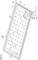
- FIG. 1 and FIG. 2 illustrate a glass panel unit (a completed product of a glass panel unit) 10 according to the first embodiment.
- the glass panel unit 10 of the first embodiment is implemented as a vacuum insulating glass panel unit.
- the vacuum insulating glass panel unit is a type of multi-pane glazing including at least one pair of glass panels, and includes a vacuum space between the pair of glass panels.
- the glass panel unit 10 of the first embodiment includes a first panel 20, a second panel 30, a seal 40, a vacuum space 50, a gas adsorbent 60, multiple pillars 70, and an occluding member 80.
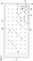
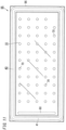
- the glass panel unit (completed product) 10 is obtained by subjecting a temporary assembly 100 shown in FIG. 3 and FIG. 4 to a predetermined process.
- the temporary assembly 100 includes the first panel 20, the second panel 30, a frame 410, an internal space 500, a partition 420, a gas passage 600, an outlet 700, the gas adsorbent 60, and the multiple pillars 70 made of resin.
- the first panel 20 includes a first glass plate 21 determining a plan shape of the first panel 20, and a coating 22.
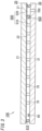
- the first glass plate 21 is a rectangular flat plate and includes a first face (lower face in FIG. 3 ) and a second face (upper face in FIG. 3 ), which are parallel to each other, on both sides in a direction of a thickness t1 (see FIG. 1 ) thereof.
- Each of the first face and the second face of the first glass plate 21 is a flat face.
- Examples of material of the first glass plate 21 may include soda lime glass, high strain point glass, chemically strengthened glass, non-alkaline glass, quartz glass, neoceram, and physically strengthened glass.
- the coating 22 is formed on the first face of the first glass plate 21.
- the coating 22 is an infrared reflective film. Note that, the coating 22 is not limited to such an infrared reflective film but may be a film with desired physical properties.
- the first panel 20 may include the first glass plate 21 alone. In short, the first panel 20 includes at least the first glass plate 21.
- the second panel 30 includes a second glass plate 31 determining a plan shape of the second panel 30.
- the second glass plate 31 is a rectangular flat plate and includes a first face (upper face in FIG. 3 ) and a second face (lower face in FIG. 3 ), which are parallel to each other, on both sides in a direction of a thickness t2 (see FIG. 1 ) thereof.
- Each of the first face and the second face of the second glass plate 31 is a flat face.
- the second panel 30 includes the second glass plate 31 alone.
- the second glass plate 31 forms the second panel 30 by itself.
- the second panel 30 may further include a coating provided at either or both faces thereof.
- the coating may be a film with desired physical properties such as an infrared reflective film.
- the second panel 30 includes the second glass plate 31 and the coating.
- the second panel 30 includes at least the second glass plate 31.
- the second panel 30 is placed to face the first panel 20.
- the first panel 20 and the second panel 30 are arranged so that the first face of the first glass plate 21 and the first face of the second glass plate 31 face and parallel to each other.
- the frame 410 is placed between the first panel 20 and the second panel 30 to hermetically bond the first panel 20 and the second panel 30 together. Thereby, the internal space 500 enclosed by the frame 410, the first panel 20, and the second panel 30 is formed.
- the frame 410 is formed of thermal adhesive (first thermal adhesive with a first softening point).
- first thermal adhesive may include glass frit.
- glass frit may include low-melting-point glass frit.
- low-melting-point glass frit may include bismuth-based glass frit, lead-based glass frit, and vanadium-based glass frit.
- the frame 410 has a rectangular frame shape.
- the frame 410 has the same plan shape as each of the first glass plate 21 and the second glass plate 31, but the frame 410 has a smaller plan size than each of the first glass plate 21 and the second glass plate 31.
- the frame 410 is formed to extend along an outer periphery of an upper face of the second panel 30 (the first face of the second glass plate31). In other words, the frame 410 is formed to surrounds an almost entire region on the upper face of the second panel 30.
- the first panel 20 and the second panel 30 are hermetically bonded with the frame 410 by once melting the first thermal adhesive of the frame 410 at a predetermined temperature (first melting temperature) Tm1 (see FIG. 6 ) equal to or higher than the first softening point.
- first melting temperature first melting temperature
- the partition 420 is placed inside the internal space 500.
- the partition 420 divides the internal space 500 into a first space 510 and a second space 520.
- the first space 510 is a space to be hermetically enclosed to form a vacuum space 50 while the glass panel unit 10 is produced, namely is a hermetically enclosed space.
- the second space 520 is a space communicated with the outlet 700, namely is an evacuation space.
- the partition 420 is formed between a first end (right end in FIG. 4 ) and a center of the second panel 30 in a lengthwise direction (left/right direction in FIG. 4 ) of the second panel 30 so that the first space 510 is larger than the second space 520.
- the partition 420 is formed of thermal adhesive (second thermal adhesive with a second softening point).
- the second thermal adhesive may include glass frit.
- the glass frit may include low-melting-point glass frit.
- Examples of the low-melting-point glass frit may include bismuth-based glass frit, lead-based glass frit, and vanadium-based glass frit.
- the second thermal adhesive may be same as the first thermal adhesive, and the second softening point may be equal to the first softening point.
- the outlet 700 is a hole interconnecting the second space 520 and an outside.
- the outlet 700 is used for evacuating the first space 510 by way of the second space 520 and the gas passage 600.
- the outlet 700 is formed in the second panel 30 to interconnect the second space 520 and the outside. In more detail, the outlet 700 is positioned in a corner of the second panel 30.
- the outlet 700 is formed in the second panel 30 in the first embodiment, but is not limited thereto. Alternatively, an outlet 700 may be formed in the first panel 20, or in each of the first panel 20 and the second panel 30.
- the gas adsorbent 60 is placed inside the first space 510.
- the gas adsorbent 60 has an elongated shape, and is formed on a second end (left end in FIG. 4 ) in the lengthwise direction of the second panel 30 to extend along the width direction of the second panel 30.
- the gas adsorbent 60 is placed on one end of the first space 510 (the vacuum space 50). According to this arrangement, the gas adsorbent 60 can be unlikely to be perceived. Further, the gas adsorbent 60 is positioned away from the partition 420 and the gas passage 600. Hence, it is possible to lower a probability that the gas adsorbent 60 prevents evacuation of the first space 510.
- the gas adsorbent 60 is used to adsorb unnecessary gas (for example, residual gas).
- the unnecessary gas may include gas emitted from the frame 410 and the partition 420 when heated.
- the gas adsorbent 60 includes a getter.
- the getter is a substance having properties of adsorbing molecules smaller than a predetermined size.
- the getter may be an evaporative getter.
- the evaporative getter has properties of desorbing adsorbed molecules when having a temperature equal to or higher than a predetermined temperature (activation temperature). Therefore, even if the adsorbability of the evaporative getter has been decreased, the adsorbability of the evaporative getter can be recovered by heating the evaporative getter to a temperature equal to or higher than the activation temperature.
- Examples of the evaporative getter may include zeolite and ion-exchanged zeolite (for example, copper ion-exchanged zeolite).
- the gas adsorbent 60 includes a powder of this getter.
- the gas adsorbent 60 may be formed by applying a liquid containing a dispersed powder of the getter.
- the gas adsorbent 60 can be downsized. Therefore, the gas adsorbent 60 can be placed even if the vacuum space 50 is small.
- the multiple pillars 70 are used to keep an interval between the first panel 20 and the second panel 30 at a predetermined interval h (see FIG. 1 ). In other words, the multiple pillars 70 serve as spacers to keep a distance between the first panel 20 and the second panel 30 to a desired value.
- the multiple pillars 70 are arranged inside the first space 510.
- the multiple pillars 70 are arranged at individual intersections of a square or rectangular lattice of constant lattice intervals including a pitch p (see FIG. 12 ).
- the multiple pillars 70 are arranged at individual intersections of a square lattice having longitudinal intervals and lateral intervals equal to the pitch p.
- the lateral intervals of the lattice may be longer than or shorter than the pitch p while the longitudinal intervals be equal to the pitch p.
- the longitudinal intervals may be longer than or shorter than the pitch p while the lateral intervals be equal to the pitch p.
- Each pillar 70 is made of light-transmissive material. Note that, each pillar 70 may be made of opaque material, providing that it is sufficiently small. Material of the pillars 70 is selected so that deformation of the pillars 70 does not occur during a first melting step, an evacuating step, and a second melting step which are described later. For example, the material of the pillars 70 is selected to have a softening point (softening temperature) higher than the first softening point of the first thermal adhesive and the second softening point of the second thermal adhesive.
- the first embodiment is characterized in the intervals of the pillars 70, which is described hereinafter.
- the pillars 70 are placed at individual intersections of a square or rectangular lattice having a pitch p (m).
- p p
- ⁇ ⁇ ⁇ P ⁇ a 2 / D
- P (N) denotes a load
- D (N ⁇ m) denotes flexural rigidity of each of the first panel 20 and the second panel 30, and ⁇ is a coefficient depending on a condition of the load.
- the flexural rigidity D is expressed by a (formula 2) below.
- D Eg ⁇ t 3 12 1 ⁇ ⁇ 2
- Eg (Pa) denotes Young's modulus of each of the first panel 20 and the second panel 30
- t (m) denotes the thickness of each of the first panel 20 and the second panel 30 described above
- v denotes Poisson's ratio of each of the first panel 20 and the second panel 30.
- ⁇ 1 ⁇ 1 ⁇ P ⁇ a 2 / D
- w (Pa) denotes the pressure (atmospheric pressure).
- ⁇ 2 ⁇ 2 ⁇ w ⁇ a 2 ⁇ a 2 / D
- a total distortion ⁇ (m) which is a sum of the distortion of the first panel 20 and the distortion of the second panel 30, is expressed by a (formula 6) below.
- ⁇ ⁇ 1 + ⁇ 2 ⁇ 2
- P 1 (N) a real load loading compression fracture, which is defined as a margin per one pillar 70 until the load acting on the pillar 70 reaches a load loading compression fracture
- P 1 can be expressed by a (formula 8) below, where P 0 (N) denotes a load loading compression fracture per one pillar 70, and w ⁇ p 2 expresses the atmospheric pressure acting on one pillar 70.
- P 1 P 0 ⁇ w ⁇ p 2
- the (formula 12) is a model formula of an ideal case where each length of four sides of the rectangle are fixed to a (m), but in an actual glass panel unit the pillars 70 are disposed discretely.
- the (formula 12) is corrected by a correction coefficient K to obtain a (formula 13) below.
- ⁇ K ⁇ 0.2016 ⁇ P 0 ⁇ p 2 / D
- the first panel 20 does not make contact with the second panel 30. Therefore, providing that the glass panel unit satisfies a (formula 15) below, the first panel 20 and the second panel 30 do not make contact with each other even when the glass panel unit receives the theoretical minimum concentric load causing the breakage of the four pillars 70. h ⁇ 0.232 ⁇ P 0 ⁇ p 2 / D > 0
- the glass panel unit satisfying the (formula 15) can reduce the probability of damaging the first panel 20 or the second panel 30, because the first panel 20 and the second panel 30 are less likely to make contact with each other even when the glass panel unit receives the theoretical minimum concentric load causing the breakage of the four pillars 70.
- a steel ball 82 having a weight of 227 (g) was fallen on the first panel 20 at an intermediate positon between two pillars 70, and it was measured a minimum height (hereinafter, referred to as a "breaking ball height") of the steel ball 82 at which at least one of the first panel 20 and the second panel 30 was broken.
- An average value of the breaking ball height was used for evaluation. It can be understood that a higher breaking ball height indicates a better resistance to the impact.
- Table 1 shows experimental conditions, a breaking ball height, and a value obtained by a discriminating expression, according to each of the experiment 1 and comparative experiments 11 to 15.
- the height of the pillar 70 equals to the interval h between the first panel 20 and the second panel 30.
- the first panel 20 and the second panel 30 are assumed to have same physical quantities, and the "Glass Panel" in the table indicates each of the first panel 20 and the second panel 30.
- the value obtained by the discriminating expression was 40 which was significantly beyond 0, and the breaking ball height was 45 (cm), concluded to be excellent.
- the value obtained by the discriminating expression according to the glass panel unit for each of the comparative experiment 11, the comparative experiment 14 and the comparative experiment 15 was negative and thus these glass panel units did not satisfy the (formula 15). Furthermore, the breaking ball heights of them were far inferior to that (45 (cm)) of the experiment 1. According to the glass panel unit for the comparative experiment 12, the value obtained by the discriminating expression was 16, which was slightly larger than 0, but the breaking ball height thereof was 12.5 (cm), which was far inferior to that of the experiment 1. According to the glass panel unit for the comparative experiment 13, the value obtained by the discriminating expression was 66, which was significantly beyond 0, but the breaking ball height thereof was 15 (cm), which was far inferior to that of the experiment 1.
- the glass panel units for the comparative experiments 11 to 13 include pillars 70 made of SUS304. According to the comparative experiments 11 to 13, it was found that the first panel 20 and/or the second panel 30 was broken at a position where the pillar 70 is provided. This can be considered that the glass panel unit according to these comparative experiments was broken due to a mechanism different from the contact between the first panel 20 and the second panel 30. According to these results, it can be concluded that the (formula 15) may be valid for the glass panel including the pillars 70 made of resin, rather than the glass panel including the pillars 70 made of SUS304.
- Table 2 shows experimental conditions, a breaking ball height, and a value obtained by the discriminating expression, according to each of the experiment 2 and comparative experiments 21 to 23.
- the value obtained by the discriminating expression was 48 which was significantly beyond 0, and the breaking ball height was 37.5 (cm), concluded to be excellent.
- the value obtained by the discriminating expression according to the glass panel unit for each of the comparative experiment 21 and the comparative experiment 23 was negative and thus these glass panel units did not satisfy the (formula 15). Furthermore, the breaking ball heights of them were far inferior to that (37.5 (cm)) of the experiment 2. According to the glass panel unit for the comparative experiment 22, the value obtained by the discriminating expression was 16, which was slightly larger than 0, but the breaking ball height thereof was far inferior to that (37.5 (cm)) of the experiment 2.
- Table 3 shows experimental conditions, a breaking ball height, and a value obtained by the discriminating expression, according to each of the experiment 3 and comparative experiments 31 to 33.
- the value obtained by the discriminating expression was 41 which was significantly beyond 0, and the breaking ball height was 50 (cm), concluded to be excellent.
- the value obtained by the discriminating expression according to the glass panel unit for each of the comparative experiment 31 and the comparative experiment 33 was negative and thus these glass panel units did not satisfy the (formula 15). Furthermore, the breaking ball heights of them were far inferior to that (50 (cm)) of the experiment 3. According to the glass panel unit for the comparative experiment 32, the value obtained by the discriminating expression was 16, which was slightly larger than 0, but the breaking ball height thereof was far inferior to that (59 (cm)) of the experiment 3.
- the aforementioned temporary assembly 100 is subjected to the above predetermined process to obtain the completed assembly 110.
- the above predetermined process includes converting the first space 510 into the vacuum space 50 by evacuating the first space 510 by way of an evacuation passage capable of evacuating gas to an outside at a predetermined temperature (an evacuation temperature) Te.
- the evacuation passage includes the gas passage 600, the second space 520, and the outlet 700.
- the evacuation temperature Te is higher than the activation temperature of the getter of the gas adsorbent 60. Consequently, evacuation of the first space 510 and recovery of the adsorbability of the getter can be performed simultaneously.
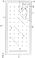
- the above predetermined process further includes forming the seal 40 enclosing the vacuum space 50 by forming a separator 42 for closing the gas passage 600 by changing a shape of the partition 420, as shown in FIG. 2 .
- the partition 420 includes the second thermal adhesive. Therefore, the separator 42 can be formed by changing the shape of the partition 420 by once melting the second thermal adhesive at a predetermined temperature (a second melting temperature) Tm2 (see FIG. 7 ) equal to or higher than the second softening point. Note that, the first melting temperature Tm1 is lower than the second melting temperature Tm2. Consequently, it is possible to prevent the gas passage 600 from being closed due to deformation of the partition 420 in bonding the first panel 20 and the second panel 30 with the frame 410.
- the partition 420 is changed in shape so that the second gas passage 620 is closed as shown in FIG. 2 .
- the separator 42 which is obtained by changing the shape of the partition 420, separates (spatially) the vacuum space 50 from the second space 520.
- the separator (second part) 42 and part (first part) 41 of the frame 410 corresponding to the vacuum space 50 constitute the seal 40 enclosing the vacuum space 50.
- the glass panel unit (completed product) 10 obtained in the aforementioned manner includes, as shown in FIG. 2 , the first panel 20, the second panel 30, the seal 40, the vacuum space 50, the second space 520, the gas adsorbent 60, the multiple pillars 70, and the occluding member 80.
- the vacuum space 50 is obtained by evacuating the first space 510 by way of the second space 520 and the outlet 700 as described above.
- the vacuum space 50 is defined as the first space 510 with a degree of vacuum equal to or lower than a predetermined value.
- the predetermined value may be 0.1 Pa, for example.
- the vacuum space 50 is hermetically enclosed by the first panel 20, the second panel 30, and the seal 40 completely and thus is separated from the second space 520 and the outlet 700.
- the seal 40 encloses the vacuum space 50 completely and bonds the first panel 20 and the second panel 30 to each other hermetically.
- the seal 40 has a frame shape, and includes the first part 41 and the second part 42.
- the first part 41 is part of the frame 410 corresponding to the vacuum space 50.
- the first part 41 is part of the frame 410 facing the vacuum space 50.
- the second part 42 is a separator formed by changing the shape of the partition 420.
- the occluding member 80 lowers the probability of foreign objects such as dusts entering the second space 520 through the outlet 700.
- the occluding member 80 includes a cover 81 provided on a front side of the outlet 700 formed in the first panel 20 or the second panel 30.
- Such an occluding member 80 provided to the outlet 700 can prevent the foreign objects such as the dust from entering the second space 520 through the outlet 700. This can prevent the visual quality of the glass panel unit 10 from being deteriorated due to the foreign object entering the second space 520 through the outlet 700.
- the occluding member 80 may be an optional element and may be omitted.
- the method for manufacturing the glass panel unit 10 of the first embodiment includes a preparation step, an assembling step, a hermetically enclosing step, and a removing step. Note that, the preparation step can be omitted.
- the preparation step is a step of forming the first panel 20, the second panel 30, the frame 410, the partition 420, the internal space 500, the gas passage 600, the outlet 700, and the gas adsorbent 60, for the purpose of producing the temporary assembly 100.
- the preparation step includes first to sixth steps. Note that, the order of the second to sixth steps may be modified.
- the first step is a step (substrate formation step) of forming the first panel 20 and the second panel 30.
- the first panel 20 and the second panel 30 are produced.
- the first step may include cleaning the first panel 20 and the second panel 30 if necessary.
- the second step is a step of forming the outlet 700.
- the outlet 700 is formed in the second panel 30. Further, in the second step, the second panel 30 is cleaned if necessary.
- the third step is a step (sealing material formation step) of forming the frame 410 and the partition 420.
- the material (the first thermal adhesive) of the frame 410 and the material (the second thermal adhesive) of the partition 420 are applied on to the second panel 30 (the first face of the second glass plate 31) with a dispenser or the like.
- the material of the frame 410 and the material of the partition 420 are dried and calcined.
- the second panel 30 where the material of the frame 410 and the material of the partition 420 are applied is heated.
- the first panel 20 may be heated together with the second panel 30.
- the first panel 20 may be heated under the same condition as the second panel 30. By doing so, it is possible to reduce a difference in degree of warp between the first panel 20 and the second panel 30.
- the fourth step is a step (pillar formation step) of forming the pillars 70.
- the fourth step may include placing the multiple pillars 70 in individual predetermined locations on the second panel 30 with a chip mounter.
- the multiple pillars 70 are formed in advance.
- the multiple pillars 70 may be formed by use of photolithography techniques and etching techniques.
- the multiple pillars 70 may be made of photocurable material or the like.
- the multiple pillars 70 may be formed by use of known thin film formation techniques.
- the multiple pillars 70 are arranged to satisfy the above (formula 15). As mentioned above, the (formula 15) is obtained without consideration with the elastic deformation of the pillars 70.
- the fifth step is a step (gas adsorbent formation step) of forming the gas adsorbent 60.
- a solution where a power of the getter is dispersed is applied to a predetermined location on the second panel 30 and then dried to thereby form the gas adsorbent 60.
- the second panel 30 is obtained, on which the frame 410, the partition 420, the gas passage 600, the outlet 700, the gas adsorbent 60, and the multiple pillars 70 are formed as shown in FIG. 5 .
- the sixth step is a step (placing step) of placing the first panel 20 and the second panel 30.
- the first panel 20 and the second panel 30 are placed so that the first face of the first glass plate 21 and the first face of the second glass plate 31 face and are parallel to each other.
- the assembling step is a step of preparing the temporary assembly 100.
- the temporary assembly 100 is prepared by bonding the first panel 20 and the second panel 30 together.
- the assembling step may be referred to as a step (first melting step) of hermetically bonding the first panel 20 and the second panel 30 together with the frame 410.
- the first thermal adhesive is melted once at the predetermined temperature (the first melting temperature) Tm1 equal to or higher than the first softening point and thereby the first panel 20 and the second panel 30 are hermetically bonded together.
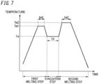
- the first panel 20 and the second panel 30 are placed in a furnace and heated at the first melting temperature Tm1 for a predetermined time (the first melting time) tm1, as shown in FIG 7 .
- the first melting temperature Tm1 and the first melting time tm1 are selected so that the first panel 20 and the second panel 30 are hermetically bonded together with the thermal adhesive of the frame 410 but the gas passage 600 is not closed by the partition 420.
- a lower limit of the first melting temperature Tm1 is equal to the first softening point
- an upper limit of the first melting temperature Tm1 is however selected so as not to cause the partition 420 to close the gas passage 600.
- the first melting temperature Tm1 is set to 440 °C.
- the first melting time tm1 may be 10 minutes, for example.
- the frame 410 may emit gas. However such gas can be adsorbed by the gas adsorbent 60.
- the temporary assembly 100 shown in FIG. 8 can be produced.
- the hermetically enclosing step is a step of subjecting the temporary assembly 100 to the above predetermined process to obtain the glass panel unit (completed product) 10.
- the hermetically enclosing step includes the evacuating step and a melting step (the second melting step). In other words, the evacuating step and the second melting step constitute the above predetermined process.
- the evacuating step is a step of converting the first space 510 into the vacuum space 50 by evacuating it by way of the gas passage 600, the second space 520, and the outlet 700 at the predetermined temperature (the evacuation temperature) Te.
- Evacuation can be done by a vacuum pump, for example.
- the vacuum pump is connected to the temporary assembly 100 with the evacuation pipe 810 and a sealing head 820.
- the evacuation pipe 810 is bonded to the second panel 30 so that an inside of the evacuation pipe 810 is connected to the outlet 700, for example.
- the sealing head 820 is attached to the evacuation pipe 810, and thereby an inlet of the vacuum pump is connected to the outlet 700.
- the first melting step, the evacuating step, and the second melting step are performed with the first panel 20 and the second panel 30 (the second panel 30 where the frame 410, the partition 420, the gas passage 600, the outlet 700, the gas adsorbent 60, and the multiple pillars 70 are formed) being left in the furnace. Therefore, the evacuation pipe 810 is bonded to the second panel 30 before the first melting step at the latest.
- the first space 510 is evacuated by way of the gas passage 600, the second space 520, and the outlet 700 at the evacuation temperature Te for a predetermined time (evacuation time) te (see FIG. 7 ).
- the evacuation temperature Te is set to be higher than the activation temperature (for example, 350 °C) of the getter of the gas adsorbent 60, and also is set to be lower than the first softening point and the second softening point (for example, 434 °C).
- the evacuation temperature Te is 390 °C.
- the getter of the gas adsorbent 60 is activated, and thus molecules (gas) adsorbed on the getter are desorbed from the getter. Such molecules (that is, gas) desorbed from the getter are discarded through the first space 510, the gas passage 600, the second space 520, and the outlet 700. Therefore, in the evacuating step, the adsorbability of the gas adsorbent 60 is recovered.
- the evacuation time te is set to obtain the vacuum space 50 having a desired degree of vacuum (for example, a degree of vacuum equal to or lower than 0.1 Pa). For example, the evacuation time te is set to 120 minutes.
- the degree of vacuum of the vacuum space 50 is not limited particularly. It may be possible that the glass panel unit includes a reduced-pressure space with a pressure smaller than 1 atm, such as 0.5 atm or the like, in place of the vacuum space 50.
- the second melting step is a step of forming the seal 40 enclosing the vacuum space 50 by changing the shape of the partition 420 to form the separator 42 closing the gas passage 600.
- the second thermal adhesive is melted once at the predetermined temperature (the second melting temperature) Tm2 equal to or higher than the second softening point, and thereby the partition 420 is changed in shape to form the separator 42.
- the first panel 20 and the second panel 30 are heated at the second melting temperature Tm2 for the predetermined time (the second melting time) tm2 in the furnace (see FIG. 7 ).
- the second melting temperature Tm2 and the second melting time tm2 are set to allow the second thermal adhesive to soften to form the separator 42 closing the gas passage 600.
- a lower limit of the second melting temperature Tm2 is equal to the second softening point (434 °C).
- the purpose of the second melting step is to change the shape of the partition 420, and consequently the second melting temperature Tm2 is set to be higher than the first melting temperature (440 °C) Tm1.
- the second melting temperature Tm2 is set to 460 °C.
- the second melting time tm2 is 30 minutes, for example.
- evacuation may be performed during the evacuating step only, before the second melting step.
- evacuation may be performed during the second melting step.
- the separator 42 closing the gas passage 600 is formed by changing the shape of the partition 420 at the second melting temperature Tm2 while the first space 510 is evacuated through the gas passage 600, the second space 520, and the outlet 700.
- the second melting step does not necessarily include evacuating the first space 510 through the gas passage 600, the second space 520, and the outlet 700.
- the glass panel unit 10 is produced.
- the pillars 70 are arranged so as to satisfy a discriminant of the above (formula 15).
- the (formula 15) is a discriminant obtained without consideration with the elastic deformation of the pillars 70.
- the first panel 20 and the second panel 30 are less likely to be damaged, because the first panel 20 is less likely to collide against the second panel 30 even when the glass panel unit 10 receives the theoretical minimum concentric load causing the breakage of the four pillars 70.
- a glass panel unit 10 of a second embodiment is described with reference to FIG. 9 and FIG. 10 .
- the glass panel unit 10 according to the second embodiment includes additional components, as well as components of the first embodiment.
- the glass panel unit 10 of the second embodiment includes a third panel 90 arranged to face a second panel 30.
- the third panel 90 faces the second panel 30 in the second embodiment, but alternatively, may face a first panel 20.
- the third panel 90 includes a third glass plate 91.
- the third glass plate 91 of the third panel 90 has a flat surface and a predetermined thickness.
- the third panel 90 includes the third glass plate 91 alone.
- the third panel 90 may further include a coating provided at either or both faces thereof.
- the coating may be a film with desired physical property such as an infrared reflective film.
- the third panel 90 includes the third glass plate 91 and the coating.
- the third panel 90 includes at least the third glass plate 91.
- the glass panel unit 10 further includes a second seal 43, which is placed between the second panel 30 and the third panel 90 to hermetically bond the second panel 30 and the third panel 90 together.
- a seal 40 may be a first seal.
- the second seal 43 is arranged in a ring between the respective peripheral portions of the second panel 30 and the third panel 90.
- the second seal 43 may be made of material same as or different from that of the seal 40 without limitation.
- the glass panel unit 10 includes a second internal space 540 which is hermetically enclosed by the second panel 30, the third panel 90 and the second seal 43 and which contains a dry gas airtightly.
- the dry gas include a dry rare gas such as an argon gas and dry air, without limitation.
- a hollow frame member 92 is arranged in a ring inside of the second seal 43 provided between the respective peripheral portions of the second panel 30 and the third panel 90.
- a through hole 921 interconnecting an inside space of the frame member 92 and the second internal space 540 is cut in the frame member 92.
- a desiccant 93 such as a silica gel is introduced in the inside space of the frame member 92.
- the second panel 30 and the third panel 90 may be bonded together in almost the same way as the first panel 20 and the second panel 30.
- an exemplary method thereof is described.
- a second thermal adhesive which later constitutes the second seal 43, on the peripheral portion of the face of either the third panel 90 or the second panel 30 in a frame shape (second thermal adhesive arranging step).
- Material of the thermal adhesive may be same as or different from material of thermal adhesive (first thermal adhesive) which later constitutes a frame 410 without limitation.
- a through hole interconnecting the second internal space 540 and an outside is formed in the thermal adhesive during this step to form a gas passage (second gas passage).
- the third panel 90 and the second panel 30 are disposed to face each other (third panel opposite disposition step).
- the thermal adhesive is melted once at temperature sufficient to melt the thermal adhesive constituting the second seal 43 and thereby the second panel 30 and the third panel 90 are hermitically bonded together with the second seal 43 (bonding step). Note that the melting is done so that the second gas passage is not completely closed during this step.
- the dry gas is introduced into the second internal space 540 through the second gas passage (dry gas introducing step).
- the second internal space 540 may be filled with the dry gas alone, or may further include residual air without limitation.
- the second seal 43 is then heated to close the second gas passage, and thereby the second internal space 540 is airtightly closed (second space closing step).
- the glass panel unit 10 is formed according the above mentioned method.
- the glass panel unit 10 of the second embodiment achieves an even higher degree of thermal insulation properties.
- the third embodiment is directed to a glass window 95 including the glass panel unit 10 of the first embodiment or the second embodiment.
- the glass window 95 of the third embodiment includes the glass panel unit 10 of any one the first embodiment and the second embodiment, and a window frame 96 with a U-cross section is fitted onto the outer peripheral portion of this glass panel unit 10.
- the glass window 95 of the third embodiment achieves an even higher degree of thermal insulation properties.
- the glass panel unit 10 is rectangular, but the glass panel unit 10 may have a desired shape such as a circular shape and a polygonal shape.
- each of the first panel 20, the second panel 30, and the seal 40 may not be rectangular and may have a desired shape such as a circular shape and a polygonal shape.
- the shapes of the first panel 20, the second panel 30, the frame 410, and the separator 42 may not be limited to the shapes described in the explanation of the above embodiments, and may have such shapes that the glass panel unit 10 can have a desired shape.
- the shape and size of the glass panel unit 10 may be determined in consideration of application of the glass panel unit 10.
- first face and the second face, of the first glass plate 21 of the first panel 20 may not be limited to flat faces.
- first face and the second face, of the second glass plate 31 of the second panel 30 may not be limited to flat faces.
- the first glass plate 21 of the first panel 20 and the second glass plate 31 of the second panel 30 may not have the same plan shape and plan size. Further, the first glass plate 21 and the second glass plate 31 may not have the same thickness. Furthermore, the first glass plate 21 and the second glass plate 31 may not be made of the same material. Similarly, the first glass plate 21 of the first panel 20 and the second glass plate 31 of the second panel 30 may not have the same plan shape and plan size. Further, the first glass plate 21 and the second glass plate 31 may not have the same thickness. Furthermore, the first glass plate 21 and the second glass plate 31 may not be made of the same material.
- the seal 40 may not have the same plan shape with the first panel 20 and the second panel 30.
- the frame 410 may not have the same plan shape with the first panel 20 and the second panel 30.
- the first panel 20 may include a coating which has desired physical properties and is formed on the second face of the first glass plate 21.
- the first panel 20 may not include the coating 22. In other words, the first panel 20 may include the first glass plate 21 alone.
- the second panel 30 may include a coating with desired physical properties.
- the coating may include at least one of thin films formed on the first face and the second face of the second glass plate 31 respectively.
- the coating may include a film reflective for light with a specified wavelength, such as an infrared reflective film or an ultraviolet reflective film.
- the frame 410 is made of the first thermal adhesive.
- the frame 410 may include other component such as a core, in addition to the first thermal adhesive.
- the frame 410 includes the first thermal adhesive.
- the frame 410 is formed to surround an almost entire region on the second panel 30.
- it is sufficient that the frame 410 is formed to surround a predetermined region on the second panel 30. In other words, there is no need to form the frame 410 so as to surround an almost entire region on the second panel 30.
- the partition 420 is made of the second thermal adhesive.
- the partition 420 may include other component such as a core, in addition to the second thermal adhesive. In other words, it is sufficient that the partition 420 includes the second thermal adhesive.
- the internal space 500 is divided into one first space 510 and one second space 520. Note that, the internal space 500 may be divided into one or more first spaces 510 and one or more second spaces 520.
- the second thermal adhesive is identical to the first thermal adhesive, and the second softening point is equal to the first softening point.
- the second thermal adhesive may be different material from the first thermal adhesive.
- the second thermal adhesive may have the second softening point different from the first softening point of the first thermal adhesive.
- the second softening point may be preferably higher than the first softening point.
- the first melting temperature Tm1 can be set to be equal to or higher than the first softening point and lower than the second softening point. By doing so, it is possible to suppress undesired deformation of the partition 420 in the first melting step.
- each of the first thermal adhesive and the second thermal adhesive may not be limited to glass frit, but may be selected from low-melting-point metal, hot-melt adhesive, and the like, for example.
- a furnace is used to heat the frame 410, the gas adsorbent 60, and the partition 420.
- heating can be done with appropriate heating means.
- the heating means may include a laser and a thermally conductive plate connected to a heat source.
- the outlet 700 is formed in the second panel 30.
- the outlet 700 may be formed in the first glass plate 21 of the first panel 20 or may be formed in the frame 410.
- a glass panel unit 10 of the first aspect includes a first panel 20 including at least a first glass plate 21; and a second panel 30 including at least a second glass plate 31.
- the second panel 30 is arranged to face the first panel 20 with a predetermined interval h left with respect to the first panel 20.
- the glass panel unit 10 includes: a seal 40 arranged between the first panel 20 and the second panel 30 to hermetically bond the first panel 20 and the second panel 30 together; and an internal space 50 configured to form a reduced-pressure space by being hermetically enclosed by the first panel 20, the second panel 30, and the seal 40.
- the glass panel unit 10 includes multiple pillars 70 made of resin.
- the multiple pillars 70 are arranged in the internal space 50 at individual intersections of a square or rectangular lattice of constant lattice intervals, including a predetermined pitch p, so as to be in contact with the first panel 20 and the second panel 30.
- the predetermined pitch p of the multiple pillars 70 is determined such that a distortion ⁇ of the first panel 20 and second panel 30 is smaller than the predetermined interval h between the first panel 20 and the second panel 30.
- the distortion ⁇ is calculated based on the predetermined pitch p, load loading compression fracture P 0 per one pillar of the multiple pillars, Young's moduli Eg of the first panel 20 and the second panel 30, thicknesses t of the first panel 20 and the second panel 30, and Poisson's ratios v of the first panel 20 and the second panel 30.
- the first panel 20 and the second panel 30 are less likely to be damaged because the first panel 20 and the second panel 30 are less likely to make contact with each other.
- the predetermined pitch p of the multiple pillars 70 is determined such that the distortion ⁇ of the first panel 20 and second panel 30 is smaller than the predetermined interval h between the first panel 20 and the second panel 30.
- the distortion ⁇ is calculated further based on Young's modulus Esp of each pillar 70, and a cross-section area S of each pillar 70, in addition to the predetermined pitch p, the predetermined interval h between the first panel 20 and the second panel 30, the load loading compression fracture P 0 per one pillar of the multiple pillars 70, the Young's moduli Eg of the first panel 20 and the second panel 30, the thicknesses t of the first panel 20 and the second panel 30, and the Poisson's ratios v of the first panel 20 and the second panel 30.
- the first panel 20 and the second panel 30 are further less likely to be damaged because the first panel 20 and the second panel 30 are further less likely to make contact with each other.
- the multiple pillars 70 are arranged so as to satisfy a formula below: h ⁇ 0.232 ⁇ P 0 ⁇ p 2 / Eg ⁇ t 3 / 12 ⁇ 1 ⁇ ⁇ 2 > 0 , where p (m) denotes the predetermined pitch, h (m) denotes the predetermined interval between the first panel 20 and the second panel 30, P 0 (N) denotes the load loading compression fracture per one pillar of the multiple pillars 70, Eg (Pa) denotes the Young's modulus of each of the first panel 20 and the second panel 30, t (m) denotes the thickness of each of the first panel 20 and the second panel 30, and v denotes the Poisson's ratio of each of the first panel 20 and the second panel 30.
- the first panel 20 and the second panel 30 are further less likely to be damaged because the first panel 20 and the second panel 30 are further less likely to make contact with each other.
- the glass panel unit 10 of the fifth aspect would be realized in combination with any one of the first to fourth aspects.
- the glass panel unit 10 includes a third panel 90 including at least a third glass plate 91 and arranged to face the second panel 30.
- the glass panel unit 10 further includes a second seal 43 arranged between the second panel 30 and the third panel 90 to hermetically bond the second panel 30 and the third panel 90 together.
- the glass panel unit 10 further includes a second internal space 540 hermetically enclosed by the second panel 30, the third panel 90, and the second seal 43 and containing a dry gas airtightly.
- the glass panel unit 10 of the fifth aspect can achieve an even higher degree of thermal insulation properties.
- a glass window 95 of the sixth aspect according to the present disclosure includes the glass panel unit 10 of any one of the first to fifth aspects, and a window frame 96 fitted onto a peripheral portion of the glass panel unit 10.
- the glass window 95 of the fourth aspect can achieve an even higher degree of thermal insulation properties.
- a method for manufacturing glass panel unit 10 of a seventh aspect according to the present disclosure includes an adhesive disposing step, a pillar arranging step, an opposite disposition step, an internal space forming step, a pressure reducing step, and a reduced-pressure space forming step.
- the adhesive disposing step includes disposing a thermal adhesive in a frame on a first panel 20 including at least a first glass plate 21.
- the pillar arranging step includes disposing multiple pillars 70 made of resin on the first panel 20 so as to be arranged at individual intersections of a square or rectangular lattice of constant lattice intervals, including a predetermined pitch p.
- the opposite disposition step includes disposing a second panel 30 including at least a second glass plate 31 to face the first panel 20.
- the internal space forming step includes heating a glass composite including the first panel 20, the second panel 30, and the thermal adhesive to melt the thermal adhesive to form an internal space 50 enclosed by the first panel 20, the second panel 30 and a melted substance of the thermal adhesive with an evacuation passage left opened to an outside, the evacuation passage being capable of evacuating gas to the outside.
- the pressure reducing step includes removing gas in the internal space 50 to reduce a pressure of the internal space 50.
- the reduced-pressure space forming step includes hermetically enclosing the internal space 50 while keeping the internal space 50 in a pressure-reduced state to form a reduced-pressure space enclosed hermetically.
- the predetermined pitch p of the multiple pillars 70 are determined such that a distortion ⁇ of the first panel 20 and second panel 30 is smaller than an interval h between the first panel 20 and the second panel 30.
- the distortion ⁇ is calculated based on the predetermined pitch p, load loading compression fracture P 0 per one pillar of the multiple pillars, Young's moduli Eg of the first panel 20 and the second panel 30, thicknesses t of the first panel 20 and the second panel 30, and Poisson's ratios v of the first panel 20 and the second panel 30.
- the first panel 20 and the second panel 30 are less likely to be damaged because the first panel 20 and the second panel 30 are less likely to make contact with each other.
- the predetermined pitch p of the multiple pillars 70 is determined such that the distortion ⁇ of the first panel 20 and second panel 30 is smaller than the interval h between the first panel 20 and the second panel 30.
- the distortion ⁇ is calculated further based on Young's modulus Esp of each pillar 70, and a cross-section area S of each pillar 70, in addition to the predetermined pitch p, the interval h between the first panel 20 and the second panel 30, the load loading compression fracture P 0 per one pillar of the multiple pillars, the Young's moduli Eg of the first panel 20 and the second panel 30, the thicknesses t of the first panel 20 and the second panel 30, and the Poisson's ratios v of the first panel 20 and the second panel 30.
- the first panel 20 and the second panel 30 are less likely to be damaged because the first panel 20 and the second panel 30 are less likely to make contact with each other.
- the multiple pillars 70 are arranged so as to satisfy a formula below: h ⁇ 0.232 ⁇ P 0 ⁇ p 2 / Eg ⁇ t 3 / 12 ⁇ 1 ⁇ ⁇ 2 > 0 , where p (m) denotes the predetermined pitch, h (m) denotes the interval between the first panel 20 and the second panel 30, P 0 (N) denotes the load loading compression fracture per one pillar of the multiple pillars 70, Eg (Pa) denotes the Young's modulus of each of the first panel 20 and the second panel 30, t (m) denotes the thickness of each of the first panel 20 and the second panel 30, and v denotes the Poisson's ratio of each of the first panel 20 and the second panel 30.
- p (m) denotes the predetermined pitch
- h (m) denotes the interval between the first panel 20 and the second panel
- P 0 (N) denotes the load loading compression fracture per one pillar of the multiple pillars
- the first panel 20 and the second panel 30 are less likely to be damaged because the first panel 20 and the second panel 30 are less likely to make contact with each other.
Landscapes
- Engineering & Computer Science (AREA)
- Chemical & Material Sciences (AREA)
- Civil Engineering (AREA)
- Structural Engineering (AREA)
- Chemical Kinetics & Catalysis (AREA)
- Life Sciences & Earth Sciences (AREA)
- Ceramic Engineering (AREA)
- General Chemical & Material Sciences (AREA)
- Geochemistry & Mineralogy (AREA)
- Materials Engineering (AREA)
- Organic Chemistry (AREA)
- Joining Of Glass To Other Materials (AREA)
- Securing Of Glass Panes Or The Like (AREA)
Claims (4)
- Glasscheibeneinheit (10), umfassend:eine erste Scheibe (20), einschließlich mindestens einer ersten Glasplatte (21);eine zweite Scheibe (30), einschließlich mindestens einer zweiten Glasplatte (31), wobei die zweite Scheibe (30) so angeordnet ist, dass sie der ersten Scheibe (20) mit einem vorgegebenen Abstand gegenüberliegt, der in Bezug auf die erste Scheibe (20) verbleibt;eine Dichtung (40), angeordnet zwischen der ersten Scheibe (20) und der zweiten Scheibe (30), um die erste Scheibe (20) und die zweite Scheibe (30) hermetisch miteinander zu verbinden;einen Innenraum (500), dazu konfiguriert, einen Unterdruckraum auszubilden, indem er von der ersten Scheibe (20), der zweiten Scheibe (30) und der Dichtung (40) hermetisch umschlossen ist; undmehrere Säulen (70) aus Harz, wobei die mehreren Säulen (70) im Innenraum (500) an individuellen Schnittpunkten eines quadratischen oder rechteckigen Gitters mit konstanten Gitterabständen, einschließlich eines vorgegebenen Abstands, so angeordnet sind, dass sie mit der ersten Scheibe (20) und der zweiten Scheibe (30) in Berührung stehen,wobeidie mehreren Säulen (70) so angeordnet sind, dass sie die folgende Formel erfüllen:
 wobei p (m) den vorgegebenen Abstand bezeichnet, h (m) den vorgegebenen Abstand zwischen der ersten Scheibe (20) und der zweiten Scheibe (30) bezeichnet, P0 (N) die Belastungskompressionsbruchrate je Säule (70) der mehreren Säulen bezeichnet, Eg (Pa) den Youngschen Modul jeder der ersten Scheibe (20) und der zweiten Scheibe (30) bezeichnet, t (m) die Dicke jeder der ersten Scheibe (20) und der zweiten Scheibe (30) bezeichnet und v die Poissonzahl jeder der ersten Scheibe (20) und der zweiten Scheibe (30) bezeichnet.
 - Glasscheibeneinheit (10) nach Anspruch 1, ferner umfassend:eine dritte Scheibe (90) einschließlich mindestens einer dritten Glasplatte (91) und so angeordnet, dass sie der zweiten Scheibe (30) gegenüberliegt;eine zweite Dichtung (42), angeordnet zwischen der zweiten Scheibe (30) und der dritten Scheibe (90), um die zweite Scheibe (30) und die dritte Scheibe (90) hermetisch miteinander zu verbinden; undeinen zweiten Innenraum (540), der durch die zweite Scheibe (30), die dritte Scheibe (90) und die zweite Dichtung (42) hermetisch umschlossen ist und ein trockenes Gas luftdicht einschließt.
- Glasfenster (95), umfassend:die Glasscheibeneinheit (10) nach Anspruch 1; undeinen Fensterrahmen (96), der auf einen Randabschnitt der Glasscheibeneinheit (10) aufgesetzt ist.
- Verfahren zum Fertigen einer Glasscheibeneinheit (10), umfassend:einen Klebstoffanordnungsschritt zum Anordnen eines Heißklebstoffs in einem Rahmen auf einer ersten Scheibe (20), die mindestens eine erste Glasplatte (21) einschließt;einen Säulenanordnungsschritt zum Anordnen mehrerer Säulen (70) aus Harz auf der ersten Scheibe (20), sodass sie an individuellen Schnittpunkten eines quadratischen oder rechteckigen Gitters mit konstanten Gitterabständen, einschließlich eines vorgegebenen Abstands, angeordnet sind;einen gegenüberliegenden Anordnungsschritt zum Anordnen einer zweiten Scheibe (30), die mindestens eine zweite Glasplatte (31) einschließt, sodass sie der ersten Scheibe (20) gegenüberliegt;einen Schritt zum Ausbilden eines Innenraums, bei dem ein Glasverbundwerkstoff erhitzt wird, der die erste Scheibe (20), die zweite Scheibe (30) und den Heißklebestoff einschließt, um den Heißklebestoff zu schmelzen und einen Innenraum (500) auszubilden, der von der ersten Scheibe (20), der zweiten Scheibe (30) und einer geschmolzenen Substanz des Heißklebestoffs umschlossen ist, wobei ein Evakuierungsdurchgang nach außen offen gelassen wird, wobei der Evakuierungsdurchgang in der Lage ist, Gas nach außen abzuleiten;einen Druckreduzierungsschritt zum Entfernen von Gas im Innenraum (500), um einen Druck des Innenraums (500) zu reduzieren; undeinen Schritt zum Ausbilden eines Unterdruckraums, bei dem der Innenraum (500) hermetisch umschlossen wird, während der Innenraum (500) in einem druckreduzierten Zustand gehalten wird, um einen hermetisch umschlossenen Unterdruckraum auszubilden,wobei der vorgegebene Abstand der mehreren Säulen (71) so bestimmt ist, dass eine Verformung der ersten Scheibe (20) und der zweiten Scheibe (30) kleiner ist als ein Abstand zwischen der ersten Scheibe (20) und der zweiten Scheibe (30), wobei die Verformung auf der Grundlage des vorbestimmten Abstands, der Belastungskompressionsbruchrate je Säule der mehreren Säulen (70), der Youngschen Module der ersten Scheibe (20) und der zweiten Scheibe (30), der Dicke der ersten Scheibe (20) und der zweiten Scheibe (30) und der Poissonzahlen der ersten Scheibe (20) und der zweiten Scheibe (30) berechnet wird, wobeidie mehreren Säulen (70) so angeordnet sind, dass sie die folgende Formel erfüllen:
 wobei p (m) den vorgegebenen Abstand bezeichnet, h (m) den Abstand zwischen der ersten Scheibe (20) und der zweiten Scheibe (30) bezeichnet, P0 (N) die Belastungskompressionsbruchrate je Säule der mehreren Säulen (70) bezeichnet, Eg (Pa) den Youngschen Modul jeder der ersten Scheibe (20) und der zweiten Scheibe (30) bezeichnet, t (m) die Dicke jeder der ersten Scheibe (20) und der zweiten Scheibe (30) bezeichnet und v die Poissonzahl jeder der ersten Scheibe (20) und der zweiten Scheibe (30) bezeichnet.
Applications Claiming Priority (2)
| Application Number | Priority Date | Filing Date | Title |
|---|---|---|---|
| JP2016194690 | 2016-09-30 | ||
| PCT/JP2017/034669 WO2018062140A1 (ja) | 2016-09-30 | 2017-09-26 | ガラスパネルユニット、ガラス窓およびガラスパネルユニットの製造方法 |
Publications (4)
| Publication Number | Publication Date |
|---|---|
| EP3521259A1 EP3521259A1 (de) | 2019-08-07 |
| EP3521259A4 EP3521259A4 (de) | 2019-10-23 |
| EP3521259B1 true EP3521259B1 (de) | 2024-12-04 |
| EP3521259C0 EP3521259C0 (de) | 2024-12-04 |
Family
ID=61759731
Family Applications (1)
| Application Number | Title | Priority Date | Filing Date |
|---|---|---|---|
| EP17856090.0A Active EP3521259B1 (de) | 2016-09-30 | 2017-09-26 | Glasscheibeneinheit, glasfenster und verfahren zur herstellung einer glasscheibeneinheit |
Country Status (4)
| Country | Link |
|---|---|
| US (1) | US11117831B2 (de) |
| EP (1) | EP3521259B1 (de) |
| JP (1) | JP6865391B2 (de) |
| WO (1) | WO2018062140A1 (de) |
Families Citing this family (7)
| Publication number | Priority date | Publication date | Assignee | Title |
|---|---|---|---|---|
| EP3786129A4 (de) * | 2018-04-27 | 2021-06-23 | Panasonic Intellectual Property Management Co., Ltd. | Glasscheibeneinheit und glasfenster |
| JP7033753B2 (ja) * | 2018-06-28 | 2022-03-11 | パナソニックIpマネジメント株式会社 | ピラー供給方法、ガラスパネルユニットの製造方法、及びピラー供給装置 |
| KR102731789B1 (ko) * | 2018-11-08 | 2024-11-21 | 엘지전자 주식회사 | 패널 어셈블리, 냉장고 및 가전제품 |
| WO2020203012A1 (ja) * | 2019-03-29 | 2020-10-08 | パナソニックIpマネジメント株式会社 | ガラスパネルユニット及びガラス窓 |
| EP3954665B1 (de) * | 2019-04-10 | 2024-07-17 | Nippon Sheet Glass Company, Limited | Glaseinheit |
| JP7660442B2 (ja) * | 2021-06-11 | 2025-04-11 | パナソニックホールディングス株式会社 | 複層ガラス |
| US12091908B2 (en) * | 2022-10-21 | 2024-09-17 | Joon Bu Park | Negative poisson's ratio materials for doors and windows |
Family Cites Families (21)
| Publication number | Priority date | Publication date | Assignee | Title |
|---|---|---|---|---|
| JPH09329783A (ja) | 1996-06-10 | 1997-12-22 | Nikon Corp | 空間光変調素子 |
| JPH1179799A (ja) * | 1997-09-04 | 1999-03-23 | Nippon Sheet Glass Co Ltd | 複層ガラス |
| JP4049443B2 (ja) | 1998-04-30 | 2008-02-20 | 日本板硝子株式会社 | ガラスパネル |
| JP2002167249A (ja) * | 2000-11-30 | 2002-06-11 | Nippon Sheet Glass Co Ltd | ガラスパネル |
| JP4109491B2 (ja) * | 2002-05-07 | 2008-07-02 | 日本板硝子株式会社 | 透光性ガラスパネル |
| CN1675140A (zh) * | 2002-08-12 | 2005-09-28 | 日本板硝子株式会社 | 玻璃面板及玻璃面板制造方法 |
| US7919157B2 (en) * | 2007-01-10 | 2011-04-05 | Guardian Industries Corp. | Vacuum IG window unit with metal member in hermetic edge seal |
| JP2008266059A (ja) | 2007-04-18 | 2008-11-06 | Nippon Sheet Glass Co Ltd | 減圧複層ガラスパネル |
| US7851034B2 (en) * | 2007-12-03 | 2010-12-14 | Guardian Industries Corp. | Embedded vacuum insulating glass unit, and/or method of making the same |
| US20100279037A1 (en) * | 2009-04-29 | 2010-11-04 | Chung-Hsien Huang | Multi-layered glass structure |
| US9228389B2 (en) * | 2010-12-17 | 2016-01-05 | Guardian Ig, Llc | Triple pane window spacer, window assembly and methods for manufacturing same |
| US9309146B2 (en) * | 2011-02-22 | 2016-04-12 | Guardian Industries Corp. | Vanadium-based frit materials, binders, and/or solvents and methods of making the same |
| KR101380486B1 (ko) | 2011-08-30 | 2014-04-01 | (주)엘지하우시스 | 배열간격이 다른 필러를 포함하는 진공유리 및 그 제조방법 |
| BR112014028689B1 (pt) * | 2012-05-18 | 2021-01-26 | Panasonic Intellectual Property Management Co., Ltd. | método de produção de chapas múltiplas |
| US9371683B2 (en) * | 2012-05-18 | 2016-06-21 | Guardian Industries Corp. | Method and apparatus for making vacuum insulated glass (VIG) window unit including pump-out tube |
| US9359808B2 (en) * | 2012-09-21 | 2016-06-07 | Ppg Industries Ohio, Inc. | Triple-glazed insulating unit with improved edge insulation |
| US9441416B2 (en) * | 2012-09-27 | 2016-09-13 | Guardian Industries Corp. | Low temperature hermetic sealing via laser |
| WO2016063007A1 (en) * | 2014-10-20 | 2016-04-28 | Pilkington Group Limited | Insulated glazing unit |
| EP3210944B1 (de) * | 2014-10-20 | 2019-10-16 | Icesun Vacuum Glass Ltd. | Vakuumplatine und herstellungsverfahren dafür |
| ES2848303T3 (es) * | 2014-11-27 | 2021-08-06 | Panasonic Ip Man Co Ltd | Unidad de paneles de vidrio |
| US10464845B2 (en) | 2015-03-13 | 2019-11-05 | Panasonic Intellectual Property Management Co., Ltd. | Method for manufacturing glass panel unit, method for manufacturing glass window, and device for manufacturing glass substrate with spacer |
-
2017
- 2017-09-26 JP JP2018542578A patent/JP6865391B2/ja active Active
- 2017-09-26 EP EP17856090.0A patent/EP3521259B1/de active Active
- 2017-09-26 WO PCT/JP2017/034669 patent/WO2018062140A1/ja not_active Ceased
- 2017-09-26 US US16/337,880 patent/US11117831B2/en active Active
Also Published As
| Publication number | Publication date |
|---|---|
| US20200024189A1 (en) | 2020-01-23 |
| JPWO2018062140A1 (ja) | 2019-07-25 |
| WO2018062140A1 (ja) | 2018-04-05 |
| US11117831B2 (en) | 2021-09-14 |
| EP3521259A4 (de) | 2019-10-23 |
| EP3521259A1 (de) | 2019-08-07 |
| JP6865391B2 (ja) | 2021-04-28 |
| EP3521259C0 (de) | 2024-12-04 |
Similar Documents
| Publication | Publication Date | Title |
|---|---|---|
| EP3521259B1 (de) | Glasscheibeneinheit, glasfenster und verfahren zur herstellung einer glasscheibeneinheit | |
| JP6544692B2 (ja) | ガラスパネルユニットの製造方法 | |
| US10597933B2 (en) | Glass panel unit and windowpane | |
| US10787856B2 (en) | Glass panel unit and glass window | |
| JP6635386B2 (ja) | 真空ガラスパネルの製造方法 | |
| JP6528335B2 (ja) | ガラスパネルユニット | |
| EP3202726A1 (de) | Glasscheibeneinheit, temporäre glasscheibenanordnung, glasscheibeneinheitsanordnung und verfahren zur herstellung einer glasscheibeneinheit | |
| JP6507461B2 (ja) | ガラスパネルユニットの製造方法およびガラス窓の製造方法 | |
| JP6775190B2 (ja) | ガラスパネルユニットおよびガラス窓 | |
| US12071371B2 (en) | Glass panel unit, work in progress of glass panel unit, glass panel unit assembly, and method for manufacturing glass panel unit | |
| US12529258B2 (en) | Glass panel unit and method for manufacturing the glass panel unit | |
| US11767706B2 (en) | Method for manufacturing glass panel unit, and method for manufacturing glass window | |
| EP3816127B1 (de) | Verfahren zur herstellung einer glasscheibeneinheit | |
| US11162297B2 (en) | Glass panel unit assembly, and method for manufacturing glass panel unit | |
| EP3825291B1 (de) | Glasplatteneinheit und verfahren zur herstellung einer glasplatteneinheit | |
| US11428041B2 (en) | Glass panel unit assembly, method for manufacturing glass panel unit, work in progress of glass panel unit, and glass panel unit | |
| US11230878B2 (en) | Glass panel unit assembly and method for manufacturing glass panel unit |
Legal Events
| Date | Code | Title | Description |
|---|---|---|---|
| STAA | Information on the status of an ep patent application or granted ep patent |
Free format text: STATUS: THE INTERNATIONAL PUBLICATION HAS BEEN MADE |
|
| PUAI | Public reference made under article 153(3) epc to a published international application that has entered the european phase |
Free format text: ORIGINAL CODE: 0009012 |
|
| STAA | Information on the status of an ep patent application or granted ep patent |
Free format text: STATUS: REQUEST FOR EXAMINATION WAS MADE |
|
| 17P | Request for examination filed |
Effective date: 20190328 |
|
| AK | Designated contracting states |
Kind code of ref document: A1 Designated state(s): AL AT BE BG CH CY CZ DE DK EE ES FI FR GB GR HR HU IE IS IT LI LT LU LV MC MK MT NL NO PL PT RO RS SE SI SK SM TR |
|
| AX | Request for extension of the european patent |
Extension state: BA ME |
|
| A4 | Supplementary search report drawn up and despatched |
Effective date: 20190923 |
|
| RIC1 | Information provided on ipc code assigned before grant |
Ipc: C03C 27/06 20060101AFI20190917BHEP Ipc: E06B 3/66 20060101ALI20190917BHEP |
|
| DAV | Request for validation of the european patent (deleted) | ||
| DAX | Request for extension of the european patent (deleted) | ||
| STAA | Information on the status of an ep patent application or granted ep patent |
Free format text: STATUS: EXAMINATION IS IN PROGRESS |
|
| 17Q | First examination report despatched |
Effective date: 20210806 |
|
| GRAP | Despatch of communication of intention to grant a patent |
Free format text: ORIGINAL CODE: EPIDOSNIGR1 |
|
| STAA | Information on the status of an ep patent application or granted ep patent |
Free format text: STATUS: GRANT OF PATENT IS INTENDED |
|
| INTG | Intention to grant announced |
Effective date: 20240215 |
|
| GRAJ | Information related to disapproval of communication of intention to grant by the applicant or resumption of examination proceedings by the epo deleted |
Free format text: ORIGINAL CODE: EPIDOSDIGR1 |
|
| STAA | Information on the status of an ep patent application or granted ep patent |
Free format text: STATUS: EXAMINATION IS IN PROGRESS |
|
| INTC | Intention to grant announced (deleted) | ||
| GRAP | Despatch of communication of intention to grant a patent |
Free format text: ORIGINAL CODE: EPIDOSNIGR1 |
|
| STAA | Information on the status of an ep patent application or granted ep patent |
Free format text: STATUS: GRANT OF PATENT IS INTENDED |
|
| INTG | Intention to grant announced |
Effective date: 20240705 |
|
| GRAS | Grant fee paid |
Free format text: ORIGINAL CODE: EPIDOSNIGR3 |
|
| GRAA | (expected) grant |
Free format text: ORIGINAL CODE: 0009210 |
|
| STAA | Information on the status of an ep patent application or granted ep patent |
Free format text: STATUS: THE PATENT HAS BEEN GRANTED |
|
| AK | Designated contracting states |
Kind code of ref document: B1 Designated state(s): AL AT BE BG CH CY CZ DE DK EE ES FI FR GB GR HR HU IE IS IT LI LT LU LV MC MK MT NL NO PL PT RO RS SE SI SK SM TR |
|
| REG | Reference to a national code |
Ref country code: GB Ref legal event code: FG4D |
|
| REG | Reference to a national code |
Ref country code: CH Ref legal event code: EP |
|
| REG | Reference to a national code |
Ref country code: DE Ref legal event code: R096 Ref document number: 602017086596 Country of ref document: DE |
|
| REG | Reference to a national code |
Ref country code: IE Ref legal event code: FG4D |
|
| U01 | Request for unitary effect filed |
Effective date: 20241230 |
|
| U07 | Unitary effect registered |
Designated state(s): AT BE BG DE DK EE FI FR IT LT LU LV MT NL PT RO SE SI Effective date: 20250114 |
|
| PG25 | Lapsed in a contracting state [announced via postgrant information from national office to epo] |
Ref country code: HR Free format text: LAPSE BECAUSE OF FAILURE TO SUBMIT A TRANSLATION OF THE DESCRIPTION OR TO PAY THE FEE WITHIN THE PRESCRIBED TIME-LIMIT Effective date: 20241204 |
|
| PG25 | Lapsed in a contracting state [announced via postgrant information from national office to epo] |
Ref country code: ES Free format text: LAPSE BECAUSE OF FAILURE TO SUBMIT A TRANSLATION OF THE DESCRIPTION OR TO PAY THE FEE WITHIN THE PRESCRIBED TIME-LIMIT Effective date: 20241204 |
|
| PG25 | Lapsed in a contracting state [announced via postgrant information from national office to epo] |
Ref country code: NO Free format text: LAPSE BECAUSE OF FAILURE TO SUBMIT A TRANSLATION OF THE DESCRIPTION OR TO PAY THE FEE WITHIN THE PRESCRIBED TIME-LIMIT Effective date: 20250304 |
|
| PG25 | Lapsed in a contracting state [announced via postgrant information from national office to epo] |
Ref country code: GR Free format text: LAPSE BECAUSE OF FAILURE TO SUBMIT A TRANSLATION OF THE DESCRIPTION OR TO PAY THE FEE WITHIN THE PRESCRIBED TIME-LIMIT Effective date: 20250305 |
|
| PG25 | Lapsed in a contracting state [announced via postgrant information from national office to epo] |
Ref country code: RS Free format text: LAPSE BECAUSE OF FAILURE TO SUBMIT A TRANSLATION OF THE DESCRIPTION OR TO PAY THE FEE WITHIN THE PRESCRIBED TIME-LIMIT Effective date: 20250304 |
|
| PG25 | Lapsed in a contracting state [announced via postgrant information from national office to epo] |
Ref country code: SM Free format text: LAPSE BECAUSE OF FAILURE TO SUBMIT A TRANSLATION OF THE DESCRIPTION OR TO PAY THE FEE WITHIN THE PRESCRIBED TIME-LIMIT Effective date: 20241204 |
|
| PG25 | Lapsed in a contracting state [announced via postgrant information from national office to epo] |
Ref country code: PL Free format text: LAPSE BECAUSE OF FAILURE TO SUBMIT A TRANSLATION OF THE DESCRIPTION OR TO PAY THE FEE WITHIN THE PRESCRIBED TIME-LIMIT Effective date: 20241204 |
|
| PG25 | Lapsed in a contracting state [announced via postgrant information from national office to epo] |
Ref country code: IS Free format text: LAPSE BECAUSE OF FAILURE TO SUBMIT A TRANSLATION OF THE DESCRIPTION OR TO PAY THE FEE WITHIN THE PRESCRIBED TIME-LIMIT Effective date: 20250404 |
|
| PG25 | Lapsed in a contracting state [announced via postgrant information from national office to epo] |
Ref country code: SK Free format text: LAPSE BECAUSE OF FAILURE TO SUBMIT A TRANSLATION OF THE DESCRIPTION OR TO PAY THE FEE WITHIN THE PRESCRIBED TIME-LIMIT Effective date: 20241204 |
|
| PG25 | Lapsed in a contracting state [announced via postgrant information from national office to epo] |
Ref country code: CZ Free format text: LAPSE BECAUSE OF FAILURE TO SUBMIT A TRANSLATION OF THE DESCRIPTION OR TO PAY THE FEE WITHIN THE PRESCRIBED TIME-LIMIT Effective date: 20241204 |
|
| PLBE | No opposition filed within time limit |
Free format text: ORIGINAL CODE: 0009261 |
|
| STAA | Information on the status of an ep patent application or granted ep patent |
Free format text: STATUS: NO OPPOSITION FILED WITHIN TIME LIMIT |
|
| PGFP | Annual fee paid to national office [announced via postgrant information from national office to epo] |
Ref country code: GB Payment date: 20250919 Year of fee payment: 9 |
|
| U20 | Renewal fee for the european patent with unitary effect paid |
Year of fee payment: 9 Effective date: 20250924 |
|
| 26N | No opposition filed |
Effective date: 20250905 |