EP3519178B1 - Visibly transparent broadband infrared mirror films - Google Patents
Visibly transparent broadband infrared mirror films Download PDFInfo
- Publication number
- EP3519178B1 EP3519178B1 EP17857246.7A EP17857246A EP3519178B1 EP 3519178 B1 EP3519178 B1 EP 3519178B1 EP 17857246 A EP17857246 A EP 17857246A EP 3519178 B1 EP3519178 B1 EP 3519178B1
- Authority
- EP
- European Patent Office
- Prior art keywords
- film
- optical
- mol
- layer
- layers
- Prior art date
- Legal status (The legal status is an assumption and is not a legal conclusion. Google has not performed a legal analysis and makes no representation as to the accuracy of the status listed.)
- Active
Links
Images
Classifications
-
- B—PERFORMING OPERATIONS; TRANSPORTING
- B32—LAYERED PRODUCTS
- B32B—LAYERED PRODUCTS, i.e. PRODUCTS BUILT-UP OF STRATA OF FLAT OR NON-FLAT, e.g. CELLULAR OR HONEYCOMB, FORM
- B32B17/00—Layered products essentially comprising sheet glass, or glass, slag, or like fibres
- B32B17/06—Layered products essentially comprising sheet glass, or glass, slag, or like fibres comprising glass as the main or only constituent of a layer, next to another layer of a specific material
-
- B—PERFORMING OPERATIONS; TRANSPORTING
- B32—LAYERED PRODUCTS
- B32B—LAYERED PRODUCTS, i.e. PRODUCTS BUILT-UP OF STRATA OF FLAT OR NON-FLAT, e.g. CELLULAR OR HONEYCOMB, FORM
- B32B27/00—Layered products comprising a layer of synthetic resin
- B32B27/06—Layered products comprising a layer of synthetic resin as the main or only constituent of a layer, which is next to another layer of the same or of a different material
- B32B27/08—Layered products comprising a layer of synthetic resin as the main or only constituent of a layer, which is next to another layer of the same or of a different material of synthetic resin
-
- B—PERFORMING OPERATIONS; TRANSPORTING
- B32—LAYERED PRODUCTS
- B32B—LAYERED PRODUCTS, i.e. PRODUCTS BUILT-UP OF STRATA OF FLAT OR NON-FLAT, e.g. CELLULAR OR HONEYCOMB, FORM
- B32B27/00—Layered products comprising a layer of synthetic resin
- B32B27/18—Layered products comprising a layer of synthetic resin characterised by the use of special additives
- B32B27/20—Layered products comprising a layer of synthetic resin characterised by the use of special additives using fillers, pigments, thixotroping agents
-
- B—PERFORMING OPERATIONS; TRANSPORTING
- B32—LAYERED PRODUCTS
- B32B—LAYERED PRODUCTS, i.e. PRODUCTS BUILT-UP OF STRATA OF FLAT OR NON-FLAT, e.g. CELLULAR OR HONEYCOMB, FORM
- B32B27/00—Layered products comprising a layer of synthetic resin
- B32B27/28—Layered products comprising a layer of synthetic resin comprising synthetic resins not wholly covered by any one of the sub-groups B32B27/30 - B32B27/42
- B32B27/285—Layered products comprising a layer of synthetic resin comprising synthetic resins not wholly covered by any one of the sub-groups B32B27/30 - B32B27/42 comprising polyethers
-
- B—PERFORMING OPERATIONS; TRANSPORTING
- B32—LAYERED PRODUCTS
- B32B—LAYERED PRODUCTS, i.e. PRODUCTS BUILT-UP OF STRATA OF FLAT OR NON-FLAT, e.g. CELLULAR OR HONEYCOMB, FORM
- B32B27/00—Layered products comprising a layer of synthetic resin
- B32B27/30—Layered products comprising a layer of synthetic resin comprising vinyl (co)polymers; comprising acrylic (co)polymers
- B32B27/304—Layered products comprising a layer of synthetic resin comprising vinyl (co)polymers; comprising acrylic (co)polymers comprising vinyl halide (co)polymers, e.g. PVC, PVDC, PVF, PVDF
-
- B—PERFORMING OPERATIONS; TRANSPORTING
- B32—LAYERED PRODUCTS
- B32B—LAYERED PRODUCTS, i.e. PRODUCTS BUILT-UP OF STRATA OF FLAT OR NON-FLAT, e.g. CELLULAR OR HONEYCOMB, FORM
- B32B27/00—Layered products comprising a layer of synthetic resin
- B32B27/32—Layered products comprising a layer of synthetic resin comprising polyolefins
- B32B27/322—Layered products comprising a layer of synthetic resin comprising polyolefins comprising halogenated polyolefins, e.g. PTFE
-
- B—PERFORMING OPERATIONS; TRANSPORTING
- B32—LAYERED PRODUCTS
- B32B—LAYERED PRODUCTS, i.e. PRODUCTS BUILT-UP OF STRATA OF FLAT OR NON-FLAT, e.g. CELLULAR OR HONEYCOMB, FORM
- B32B27/00—Layered products comprising a layer of synthetic resin
- B32B27/32—Layered products comprising a layer of synthetic resin comprising polyolefins
- B32B27/325—Layered products comprising a layer of synthetic resin comprising polyolefins comprising polycycloolefins
-
- B—PERFORMING OPERATIONS; TRANSPORTING
- B32—LAYERED PRODUCTS
- B32B—LAYERED PRODUCTS, i.e. PRODUCTS BUILT-UP OF STRATA OF FLAT OR NON-FLAT, e.g. CELLULAR OR HONEYCOMB, FORM
- B32B27/00—Layered products comprising a layer of synthetic resin
- B32B27/36—Layered products comprising a layer of synthetic resin comprising polyesters
-
- B—PERFORMING OPERATIONS; TRANSPORTING
- B32—LAYERED PRODUCTS
- B32B—LAYERED PRODUCTS, i.e. PRODUCTS BUILT-UP OF STRATA OF FLAT OR NON-FLAT, e.g. CELLULAR OR HONEYCOMB, FORM
- B32B7/00—Layered products characterised by the relation between layers; Layered products characterised by the relative orientation of features between layers, or by the relative values of a measurable parameter between layers, i.e. products comprising layers having different physical, chemical or physicochemical properties; Layered products characterised by the interconnection of layers
- B32B7/02—Physical, chemical or physicochemical properties
-
- B—PERFORMING OPERATIONS; TRANSPORTING
- B32—LAYERED PRODUCTS
- B32B—LAYERED PRODUCTS, i.e. PRODUCTS BUILT-UP OF STRATA OF FLAT OR NON-FLAT, e.g. CELLULAR OR HONEYCOMB, FORM
- B32B7/00—Layered products characterised by the relation between layers; Layered products characterised by the relative orientation of features between layers, or by the relative values of a measurable parameter between layers, i.e. products comprising layers having different physical, chemical or physicochemical properties; Layered products characterised by the interconnection of layers
- B32B7/04—Interconnection of layers
- B32B7/12—Interconnection of layers using interposed adhesives or interposed materials with bonding properties
-
- G—PHYSICS
- G02—OPTICS
- G02B—OPTICAL ELEMENTS, SYSTEMS OR APPARATUS
- G02B5/00—Optical elements other than lenses
- G02B5/20—Filters
- G02B5/28—Interference filters
- G02B5/281—Interference filters designed for the infrared light
-
- G—PHYSICS
- G02—OPTICS
- G02B—OPTICAL ELEMENTS, SYSTEMS OR APPARATUS
- G02B5/00—Optical elements other than lenses
- G02B5/20—Filters
- G02B5/28—Interference filters
- G02B5/281—Interference filters designed for the infrared light
- G02B5/282—Interference filters designed for the infrared light reflecting for infrared and transparent for visible light, e.g. heat reflectors, laser protection
-
- B—PERFORMING OPERATIONS; TRANSPORTING
- B32—LAYERED PRODUCTS
- B32B—LAYERED PRODUCTS, i.e. PRODUCTS BUILT-UP OF STRATA OF FLAT OR NON-FLAT, e.g. CELLULAR OR HONEYCOMB, FORM
- B32B2250/00—Layers arrangement
- B32B2250/05—5 or more layers
-
- B—PERFORMING OPERATIONS; TRANSPORTING
- B32—LAYERED PRODUCTS
- B32B—LAYERED PRODUCTS, i.e. PRODUCTS BUILT-UP OF STRATA OF FLAT OR NON-FLAT, e.g. CELLULAR OR HONEYCOMB, FORM
- B32B2250/00—Layers arrangement
- B32B2250/24—All layers being polymeric
-
- B—PERFORMING OPERATIONS; TRANSPORTING
- B32—LAYERED PRODUCTS
- B32B—LAYERED PRODUCTS, i.e. PRODUCTS BUILT-UP OF STRATA OF FLAT OR NON-FLAT, e.g. CELLULAR OR HONEYCOMB, FORM
- B32B2250/00—Layers arrangement
- B32B2250/42—Alternating layers, e.g. ABAB(C), AABBAABB(C)
-
- B—PERFORMING OPERATIONS; TRANSPORTING
- B32—LAYERED PRODUCTS
- B32B—LAYERED PRODUCTS, i.e. PRODUCTS BUILT-UP OF STRATA OF FLAT OR NON-FLAT, e.g. CELLULAR OR HONEYCOMB, FORM
- B32B2255/00—Coating on the layer surface
- B32B2255/10—Coating on the layer surface on synthetic resin layer or on natural or synthetic rubber layer
-
- B—PERFORMING OPERATIONS; TRANSPORTING
- B32—LAYERED PRODUCTS
- B32B—LAYERED PRODUCTS, i.e. PRODUCTS BUILT-UP OF STRATA OF FLAT OR NON-FLAT, e.g. CELLULAR OR HONEYCOMB, FORM
- B32B2255/00—Coating on the layer surface
- B32B2255/26—Polymeric coating
-
- B—PERFORMING OPERATIONS; TRANSPORTING
- B32—LAYERED PRODUCTS
- B32B—LAYERED PRODUCTS, i.e. PRODUCTS BUILT-UP OF STRATA OF FLAT OR NON-FLAT, e.g. CELLULAR OR HONEYCOMB, FORM
- B32B2255/00—Coating on the layer surface
- B32B2255/28—Multiple coating on one surface
-
- B—PERFORMING OPERATIONS; TRANSPORTING
- B32—LAYERED PRODUCTS
- B32B—LAYERED PRODUCTS, i.e. PRODUCTS BUILT-UP OF STRATA OF FLAT OR NON-FLAT, e.g. CELLULAR OR HONEYCOMB, FORM
- B32B2270/00—Resin or rubber layer containing a blend of at least two different polymers
-
- B—PERFORMING OPERATIONS; TRANSPORTING
- B32—LAYERED PRODUCTS
- B32B—LAYERED PRODUCTS, i.e. PRODUCTS BUILT-UP OF STRATA OF FLAT OR NON-FLAT, e.g. CELLULAR OR HONEYCOMB, FORM
- B32B2307/00—Properties of the layers or laminate
- B32B2307/20—Properties of the layers or laminate having particular electrical or magnetic properties, e.g. piezoelectric
- B32B2307/206—Insulating
-
- B—PERFORMING OPERATIONS; TRANSPORTING
- B32—LAYERED PRODUCTS
- B32B—LAYERED PRODUCTS, i.e. PRODUCTS BUILT-UP OF STRATA OF FLAT OR NON-FLAT, e.g. CELLULAR OR HONEYCOMB, FORM
- B32B2307/00—Properties of the layers or laminate
- B32B2307/40—Properties of the layers or laminate having particular optical properties
- B32B2307/402—Coloured
-
- B—PERFORMING OPERATIONS; TRANSPORTING
- B32—LAYERED PRODUCTS
- B32B—LAYERED PRODUCTS, i.e. PRODUCTS BUILT-UP OF STRATA OF FLAT OR NON-FLAT, e.g. CELLULAR OR HONEYCOMB, FORM
- B32B2307/00—Properties of the layers or laminate
- B32B2307/40—Properties of the layers or laminate having particular optical properties
- B32B2307/412—Transparent
-
- B—PERFORMING OPERATIONS; TRANSPORTING
- B32—LAYERED PRODUCTS
- B32B—LAYERED PRODUCTS, i.e. PRODUCTS BUILT-UP OF STRATA OF FLAT OR NON-FLAT, e.g. CELLULAR OR HONEYCOMB, FORM
- B32B2307/00—Properties of the layers or laminate
- B32B2307/40—Properties of the layers or laminate having particular optical properties
- B32B2307/416—Reflective
-
- B—PERFORMING OPERATIONS; TRANSPORTING
- B32—LAYERED PRODUCTS
- B32B—LAYERED PRODUCTS, i.e. PRODUCTS BUILT-UP OF STRATA OF FLAT OR NON-FLAT, e.g. CELLULAR OR HONEYCOMB, FORM
- B32B2307/00—Properties of the layers or laminate
- B32B2307/40—Properties of the layers or laminate having particular optical properties
- B32B2307/418—Refractive
-
- B—PERFORMING OPERATIONS; TRANSPORTING
- B32—LAYERED PRODUCTS
- B32B—LAYERED PRODUCTS, i.e. PRODUCTS BUILT-UP OF STRATA OF FLAT OR NON-FLAT, e.g. CELLULAR OR HONEYCOMB, FORM
- B32B2307/00—Properties of the layers or laminate
- B32B2307/40—Properties of the layers or laminate having particular optical properties
- B32B2307/42—Polarizing, birefringent, filtering
-
- B—PERFORMING OPERATIONS; TRANSPORTING
- B32—LAYERED PRODUCTS
- B32B—LAYERED PRODUCTS, i.e. PRODUCTS BUILT-UP OF STRATA OF FLAT OR NON-FLAT, e.g. CELLULAR OR HONEYCOMB, FORM
- B32B2307/00—Properties of the layers or laminate
- B32B2307/70—Other properties
- B32B2307/708—Isotropic
-
- B—PERFORMING OPERATIONS; TRANSPORTING
- B32—LAYERED PRODUCTS
- B32B—LAYERED PRODUCTS, i.e. PRODUCTS BUILT-UP OF STRATA OF FLAT OR NON-FLAT, e.g. CELLULAR OR HONEYCOMB, FORM
- B32B2307/00—Properties of the layers or laminate
- B32B2307/70—Other properties
- B32B2307/732—Dimensional properties
-
- B—PERFORMING OPERATIONS; TRANSPORTING
- B32—LAYERED PRODUCTS
- B32B—LAYERED PRODUCTS, i.e. PRODUCTS BUILT-UP OF STRATA OF FLAT OR NON-FLAT, e.g. CELLULAR OR HONEYCOMB, FORM
- B32B2419/00—Buildings or parts thereof
-
- B—PERFORMING OPERATIONS; TRANSPORTING
- B32—LAYERED PRODUCTS
- B32B—LAYERED PRODUCTS, i.e. PRODUCTS BUILT-UP OF STRATA OF FLAT OR NON-FLAT, e.g. CELLULAR OR HONEYCOMB, FORM
- B32B2605/00—Vehicles
- B32B2605/006—Transparent parts other than made from inorganic glass, e.g. polycarbonate glazings
-
- G—PHYSICS
- G02—OPTICS
- G02B—OPTICAL ELEMENTS, SYSTEMS OR APPARATUS
- G02B5/00—Optical elements other than lenses
- G02B5/08—Mirrors
- G02B5/0816—Multilayer mirrors, i.e. having two or more reflecting layers
- G02B5/0825—Multilayer mirrors, i.e. having two or more reflecting layers the reflecting layers comprising dielectric materials only
- G02B5/0841—Multilayer mirrors, i.e. having two or more reflecting layers the reflecting layers comprising dielectric materials only comprising organic materials, e.g. polymers
Definitions
- This disclosure relates to multilayer infrared (IR) reflecting films that are visibly transparent, and methods of making and using the same.
- multilayer polymeric films to reflect light is known and is described, for example, in U.S. Patent No. 6,667,095 (Wheatley et al. ), U.S. Patent No. 5360659 (Arends et al. ), and U.S. Patent No. 5,103,337 (Schrenk et al. ).
- a multilayer film designed to reflect infrared light may also have higher order reflections in the visible region of the spectrum. These higher order reflections may be undesirable in many applications (e.g., window films). In order to design infrared reflective films that are capable of reflecting light in the infrared region, but do not reflect light over the visible region, the higher order reflections need to be suppressed.
- Patent application US2011255155A1 discloses an article comprising an optical stack, wherein the optical stack comprises a plurality of first optical layers, each first optical layer comprising a melt-processible copolymer comprising interpolymerized monomers of tetrafluoroethylene.
- the melt-processible copolymer is not fluorinated ethylene-propylene copolymer or a perfluoroalkoxy resin.
- the optical stack further comprises a second polymer layer disposed in a repeating sequence with the plurality of first optical layers, each second optical layer comprising a non-fluorinated polymeric material.
- Patent application US2005186408A1 discloses optical bodies comprising: (a) a plurality of first optical layers, each first optical layer being oriented; and (b) a plurality of second optical layers, disposed in a repeating sequence with the plurality of first optical layers, comprising a blend of polymethylmethacrylate and polyvinylidene fluoride.
- Patent application US2011249325A1 discloses a multilayer optical film comprising first optical layers of a first fluoropolymeric material and second optical layers of a second fluoropolymeric material wherein at least a portion of the first layers and at least a portion of the second layers are in intimate contact.
- the present disclosure describes a multilayer infrared (IR) reflecting film.
- the film includes an optical repeating unit including a plurality of optical polymeric layers arranged to reflect light by constructive and destructive interference.
- the plurality of optical polymeric layers include optical layers A and B wherein the plurality of polymeric layers of the optical repeating unit are arranged in an order ABABAB with the thickness ratio of about 7:1:1:7:1:1.
- the optical layer A is a high refractive index polymeric layer
- the optical layer B is a low refractive index isotropic polymeric layer including one or more fluoropolymers.
- some embodiments of the present disclosure may have protective skin layers on one or both sides of the optical layer stack.
- the film has an average reflectance from about 50% to about 100% in a near infrared wavelength range of about 850 nm to about 1850 nm, and the film has an average transmission from about 70% to about 90% in a visible light range, the optical layer A absorbs less than 1% light in an ultraviolet (UV) wavelength range of about 350 nm to about 400 nm.
- UV ultraviolet
- the present disclosure describes a window having a major surface, and said multilayer infrared (IR) reflecting film is provided on the major surface.
- IR infrared
- the multilayer IR reflecting films can exhibit superior optical properties (e.g., high IR light reflectance, and high visible light transmission) by utilizing fluoropolymer low refractive index polymers in combination with higher order harmonic suppressive optical designs.
- An optical repeating unit of the film includes a plurality of polymeric layers arranged to reflect light by constructive and destructive interference.
- the plurality of polymeric layers include optical layers A and B.
- the optical layer A is a high refractive index polymeric layer
- the optical layer B is a low refractive index isotropic polymeric layer including one or more fluoropolymers.
- the film has an average reflectance from about 50% to about 100% in a near infrared wavelength range of about 850 nm to about 1850 nm, and the film has an average transmission from about 70% to about 90% in a visible light range. In some cases, the film has low CIE (L ⁇ , a ⁇ , b ⁇ ) color values with -5.0 ⁇ a ⁇ ⁇ 5.0 and -5.0 ⁇ b ⁇ ⁇ 5.0.
- the terms "reflective,” “reflectivity,” “reflection,” “reflecting,” or “reflectance” refer to total reflectance of a sufficiently specular nature.
- optical repeating unit refers to a stack of optical layers arranged in a particular arrangement which is repeated across the thickness of a multilayer film.
- in-plane axes refers to two mutually perpendicular axes disposed in the plane of the film. In the present application, these axes are typically designated as the x-axis and the y-axis.
- transverse axis refers to an axis that is perpendicular to the plane of the film. In the present application, this axis is typically designated as the z-axis.
- birefringence refers to the situation in which the index of refraction along the transverse axis n z is different from the index of refraction along one or both in-plane axes n x or n y .
- the terms “transparent' and “optically transparent” are used interchangeably and refer to an article, film, polymeric blend, or adhesive that has a high light transmittance (e.g., at least 70 percent such as at least 80 percent, at least 85 percent, at least 90 percent, at least 95 percent, at least 97 percent, at least 98 percent, or at least 99 percent) over at least a portion of the visible light spectrum (about 400 to about 700 nanometers (nm)). In many embodiments, the high transmittance is over the entire visible light spectrum.
- a high light transmittance e.g., at least 70 percent such as at least 80 percent, at least 85 percent, at least 90 percent, at least 95 percent, at least 97 percent, at least 98 percent, or at least 99 percent
- the high transmittance is over the entire visible light spectrum.
- polymer refers to a polymeric material that is a homopolymer, copolymer, terpolymer, or the like.
- homopolymer refers to a polymeric material that is the reaction product of a single monomer.
- copolymer refers to a polymeric material that is the reaction product of two different monomers or polymer blends and the term “terpolymer” refers to a polymeric material that is the reaction product of three different monomers or polymer blends. It is to be understood that the terms “polymer” and “copolymer” in the present disclosure may include both random and block copolymers.
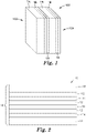
- Figure 1 is a schematic illustration of a 711 layer construction for use in a multilayer IR reflecting film, according to one embodiment.
- an optical repeating unit 100 in the multilayer IR reflecting film has six optical layers including alternating polymeric layers A and B arranged with layer thickness ratios of approximately 7A1B1A7B1A1B.
- the 711 layer construction can suppress the unwanted high order reflections (e.g., second, third, and fourth order reflections) in the visible wavelength region from about 400 to about 700 nm, while reflecting light in the infrared wavelength region from about 700 to about 2000 nm, preferably from about 850 to about 2000 nm.
- the optical polymeric layer A may be a birefringent layer and the optical polymeric layer B may be an isotropic layer. In some embodiments, the polymeric layer A may be an isotropic layer.
- the polymeric material of optical layer A has a first in-plane refractive index n 1 .
- the optical polymeric layer B has a second in-plane refractive index n 2 .
- the in-plane refractive index n 1 of optical layer A is greater than that of optical layer B n 2 .
- the first in-plane refractive index n 1 may be in the range of, for example, about 1.62 to about 1.68.
- the second in-plane refractive index n 2 of optical layer B may be in a range of, for example, about 1.34 to about 1.40.
- the in-plane refractive index difference between n 1 and n 2 can be, for example, at least 0.20, at least 0.22, at least 0.24, at least 0.26, at least 0.28, at least 0.30, or at least 0.32.
- the difference between the first and second in-plane refractive indices n 1 and n 2 may be in the range of, for example, about 0.26 to about 0.32.
- the multilayer IR reflecting film may require fewer layers to achieve the desired optical power, e.g., IR light reflectivity.
- a multilayer IR reflecting film may include multiple optical repeating units 100 of Fig. 1 that are stacked along the film thickness direction.
- the multiple stacked optical repeating units 100 can be laminated to a substantially transparent substrate such as, for example, a polymer substrate, a glass substrate, etc.
- one or more boundary polymeric layers can be provided for the optical repeating unit 100 onto faces 102 and/or 104 thereof. Exemplary boundary layers are described in U.S. Patent No. 6,927,900 (Liu et al. ).
- the stacked optical repeating units 100 may not have the same optical thickness, but have a layer thickness gradient across the thickness of the film to achieve the desired band-width of reflection.
- the layer thickness gradient may vary widely depending on the intended application for the film.
- the layer thickness gradient may be linear, in which the optical thickness of the optical repeating units increases at a constant rate across the thickness of the film.
- each unit or unit cell is a certain amount thicker than the thickness of the previous unit in the multilayer stack.
- each unit may be a certain percentage thicker than the thickness of the previous unit.
- the layer thickness may decrease, then increase, then decrease again from one major surface of the film to the other, or may have an alternate layer thickness distribution designed to increase the sharpness of one or both band edges.
- Preferred polymers for polymeric layer A may include suitable polyesters such as, for example, polyethylene terephthalate (PET).
- PET polyethylene terephthalate
- PET polyethylene terephthalate
- Its refractive index for polarized incident light of 550 nm wavelength increases when the plane of polarization is parallel to the stretch direction from about 1.57 to as high as about 1.69.
- Increasing molecular orientation increases the birefringence of PET. The molecular orientation may be increased by stretching the material to greater stretch ratios and holding other stretching conditions fixed.
- Copolymers of PET CoPET), such as those described in U.S. Pat. No. 6,744,561 (Condo et al.
- U.S. Pat. No. 6,449,093 (Hebrink et al. ), are particularly useful for their relatively low temperature (typically less than 250°C) processing capability making them more coextrusion compatible with less thermally stable second polymers.
- Other semicrystalline polyesters suitable as birefringent polymers may include, for example, polybutylene terephthalate (PBT), polyethylene terephthalate (PET), and/or copolymers thereof such as those described in U.S. Pat. No. 6,449,093 B2 (Hebrink et al. ) or U.S. Pat. Pub. No. 20060084780 (Hebrink et al. ).
- Polyesters suitable for use in some exemplary multilayer optical films constructed according to the present disclosure may generally include carboxylate and glycol subunits. Suitable polyesters can be generated by reactions of carboxylate monomer molecules with glycol monomer molecules. Each carboxylate monomer molecule has two or more carboxylic acid or ester functional groups and each glycol monomer molecule has two or more hydroxy functional groups. The carboxylate monomer molecules may all be the same or there may be two or more different types of molecules. The same applies to the glycol monomer molecules. Also included within the term "polyester” are polycarbonates derived from the reaction of glycol monomer molecules with esters of carbonic acid.
- Suitable carboxylate monomer molecules for use in forming the carboxylate subunits of the polyester layers include, for example, 1,4-terephthalate dicarboxylic acid and isomers thereof; terephthalic acid; isophthalic acid; phthalic acid; azelaic acid; adipic acid; sebacic acid; norbornene dicarboxylic acid; bi-cyclo-octane dicarboxylic acid; 1,4-cyclohexane dicarboxylic acid and isomers thereof; t-butyl isophthalic acid, trimellitic acid, sodium sulfonated isophthalic acid; 4,4'-biphenyl dicarboxylic acid and isomers thereof; and lower alkyl esters of these acids, such as methyl or ethyl esters.
- lower alkyl refers, in this context, to C1-C10 straight-chained or branched alkyl groups.
- Suitable glycol monomer molecules for use in forming glycol subunits of the polyester layers include ethylene glycol; propylene glycol; 1,4-butanediol and isomers thereof; 1,6-hexanediol; neopentyl glycol; polyethylene glycol; diethylene glycol; tricyclodecanediol; 1,4-cyclohexanedimethanol and isomers thereof; norbornanediol; bicyclo-octanediol; trimethylol propane; pentaerythritol; 1,4-benzenedimethanol and isomers thereof; bisphenol A; 1,8-dihydroxy biphenyl and isomers thereof; and 1,3-bis (2-hydroxyethoxy)benzene.
- the optical layer A may include an isotropic polymer.
- Exemplary isotropic optical polymers, especially for use in the optical layer A may include homopolymers of polymethylmethacrylate (PMMA), such as those available from Ineos Acrylics, Inc., Wilmington, DE, under the trade designations "CP71” and "CP80;” and polyethyl methacrylate (PEMA), which has a lower glass transition temperature than PMMA.
- PMMA polymethylmethacrylate
- PEMA polyethyl methacrylate
- Additional useful polymers include copolymers of PMMA (CoPMMA), such as a CoPMMA made from 75 wt.% methylmethacrylate (MMA) monomers and 25 wt.% ethyl acrylate (EA) monomers, (available from Ineos Acrylics, Inc., under the trade designation "PERSPEX CP63” or Arkema, Philadelphia, PA, under the trade designation "ATOGLAS 510”), a CoPMMA formed with MMA comonomer units and n-butyl methacrylate (nBMA) comonomer units, or a blend of PMMA and poly(vinylidene fluoride) (PVDF).
- CoPMMA copolymers of PMMA
- CoPMMA such as a CoPMMA made from 75 wt.% methylmethacrylate (MMA) monomers and 25 wt.% ethyl acrylate (EA) monomers, (available from Ineos Acrylics, Inc., under
- Additional exemplary optical polymers for Layer A include acrylate triblock copolymers, where each endblock of at least one of the first block copolymer, the second block copolymer, or the at least one additional block copolymer is comprised of poly(methyl methacrylate), and further wherein each midblock of at least one of the first block copolymer or the second block copolymer is comprised of poly(butyl acrylate).
- at least one of the first block copolymer, the second block copolymer, or the at least one additional block copolymer is comprised of from 30 wt. % to 80 wt. % endblocks, and from 20 wt. % to 70 wt.
- At least one of the first block copolymer, the second block copolymer, or the at least one additional block copolymer is comprised of from 50 wt. % to 70 wt. % endblocks, and from 30 wt. % to 50 wt. % midblocks, based on the total weight of the respective block copolymer.
- the first block copolymer may be selected to be the same as the second block copolymer.
- Triblock acrylate copolymers are available, for example, under the tradename Kurarity LA4285, available from Kuraray America Inc., Houston, TX.
- Additional suitable polymers for the optical layers, especially for use in the optical layer A may include polyolefin copolymers such as poly (ethylene-co-octene) (PE-PO) available from Dow Elastomers, Midland, MI, under the trade designation "ENGAGE 8200,” poly (propylene-co-ethylene) (PPPE) available from Atofina Petrochemicals, Inc., Houston, TX, under the trade designation "Z9470,” and a copolymer of atactic polypropylene (aPP) and isotatctic polypropylene (iPP).
- PE-PO poly (ethylene-co-octene)
- PPPE poly (propylene-co-ethylene)
- Z9470 Atofina Petrochemicals, Inc., Houston, TX
- aPP atactic polypropylene
- iPP isotatctic polypropylene
- the multilayer optical films can also include, for example, in the second layers, a functionalized polyolefin, such as linear low density polyethylene-graft-maleic anhydride (LLDPE-g-MA) such as that available from E.I. duPont de Nemours & Co., Inc., Wilmington, DE, under the trade designation "BYNEL 4105.”
- a functionalized polyolefin such as linear low density polyethylene-graft-maleic anhydride (LLDPE-g-MA) such as that available from E.I. duPont de Nemours & Co., Inc., Wilmington, DE, under the trade designation "BYNEL 4105.”
- the materials for optical layer A do not absorb a significant amount of light in an ultraviolet (UV) range of about 350 nm to about 400 nm.
- the optical layer A may absorb, for example, less than 5%, less than 3%, less than 1%, or less than 0.5% of incident UV light.
- the high refractive index polymeric layer A may not include crystalline or semi-crystalline polyethylenenaphthalate (PEN) and its isomers (e.g. 2,6-; 1,4-; 1,5-; 2,7; and 2,3-PEN).
- the amount of PEN in the optical layer A may be lower than 5 mol%, lower than 1 mol%, lower than 0.5 mol%, lower than 0.2 mol%, lower than 0.1 mol%, or about 0 mol%. While PEN was claimed to have improvements in strength and chemical and hydrolytic resistance, gaseous barrier, thermal and thermo-oxidative resistance and ultraviolet (UV) light barrier resistance compared to PET, the present disclosure found that including a PEN layer as polymeric layer A in the IR reflective multilayer films described herein may introduce stability issues for potential UV degradation of the films.
- UV ultraviolet
- Preferred polymers for optical layer B may have comonomer compositions including tetrafluoroethylene (TFE) and hexafluoropropylene (HFP).
- the polymeric layer B may include about 30 mol% to about 80 mol% of tetrafluoroethylene (TFE), and about 20 mol% to about 70 mol% of hexafluoropropylene (HFP).
- the layer B may include about 30 mol% to about 75 mol% of tetrafluoroethylene (TFE), about 5 mol% to about 30 mol% of hexafluoropropylene (HFP), about 0 to about 55 mol% of vinylidene fluoride (VDF), and about 0 to about 15 mol% of perfluoropropylvinyl ether (PPVE).
- TFE tetrafluoroethylene
- HFP hexafluoropropylene
- VDF vinylidene fluoride
- PPVE perfluoropropylvinyl ether
- the optical polymeric layer B may include about 35 mol% to about 80 mol% of tetrafluoroethylene (TFE), about 5 mol% to about 50 mol% of hexafluoropropylene (HFP), and about 0 to about 15 mol% of perfluoropropylvinyl ether (PPVE).
- TFE tetrafluoroethylene
- HFP hexafluoropropylene
- PPVE perfluoropropylvinyl ether
- the present description provides suitable comonomer compositions for polymeric layer B, in combination with the polyester layer A, to achieve desired optical and mechanical properties.
- the polymeric layers A and B can have sufficient interfacial adhesion to prevent delamination.
- the polymeric layer B may include a fluoropolymer commercially available from 3M Company (Saint Paul, MN, USA) under the trade designation THV, which are terpolymers of tetrafluoroethylene, hexafluoropropylene, and vinylidene fluoride.
- the polymeric layer B may include four or more monomers, including PPVE, for improved interlayer adhesion with polymeric layer A.
- the polymeric layer B may preferably include FEP (fluoroinated Ethylene Propylene) copolymers and PPVE, which are considered advantageous for their low refractive index and potential for excellent interlayer adhesion.
- Fluoropolymers useful as the polymer matrix in optical layer B may include fluorocarbon resins.
- Fluorinated ethylene-propylene copolymer i.e., FEP
- FEP Fluorinated ethylene-propylene copolymer
- Perfluoroalkoxy resin i.e., PFA
- Polymeric materials including tetrafluoroethylene with hexafluoroethylene and/or a vinyl ether, which are outside of the ASTM designations listed above are also contemplated.
- melt-processable copolymers including interpolymerized monomers of tetrafluoroethylene may include, for example, copolymers of tetrafluoroethylene, hexafluoropropylene, and vinylidene fluoride (e.g., THV); copolymers of tetrafluoroethylene, hexafluoropropylene, and ethylene (e.g., HTE), copolymers of tetrafluoroethylene and norbornene; copolymers of ethylene and tetrafluoroethylene (e.g., ETFE): copolymers of tetrafluoroethylene, hexafluoropropylene, and ethylene (e.g., TFEP); or combinations thereof.
- exemplary fluoropolymers useful as the polymer matrix in layer B include THV available under the trade designation "DYNEON THV 221 Grade”, “DYNEON THV 2030 Grade”, “DYNEON THV 500 Grade”, “DYNEON THV610 Grade”, “DYNEON THV 815 Grade”, and “DYNEON HTEX 1705 Grade”, “DYNEON FEP Grade”, all available from Dyneon LLC, Oakdale, MN.
- Table 1 below lists interlayer adhesion values (i.e., average delamination force) for the combination of PET/THV as optical layers A and B where layer B of THV is available with various grades A-F.
- Table 2 below lists interlayer adhesion values (i.e., average delamination force) for the combination of PMMA/THV as layers A and B where layer B of THV is available with various grades A-F. It can be seen in Table 1 that fluoropolymers containing a higher level of VDF (vinylidene fluoride) and or PPV (perflouropropyl vinylether) may have better interlayer adhesion to PET (polyethylene terephthalate).
- VDF vinylene fluoride
- PPV perflouropropyl vinylether
- the combination of PMMA/THV may exhibit greater interlayer adhesion than the combination of PET/THV, while the combination of PET/THV may exhibit greater optical power (e.g., reflectivity) with the same number of optical layers since its greater refractive index difference.
- Some grades of THV may have greater interlayer adhesion with PET or PMMA than others.
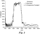
- Figure 2 is a schematic illustration of a multilayer optical body 10 for use in a multilayer IR reflecting film, which is not part of the invention, but for reference only.
- the optical multilayer optical body 10 includes multiple optical repeating units, i.e., alternating pairs of optical layer A 12 and optical layer B 14.
- the optical layers 12 and 14 are typically interleaved to form a stack 16 of layers, optionally, with one or more of non-optical layers 18 disposed on a surface of the stack 16 as a skin layer.
- the relative optical thicknesses of the optical layers A and B can be about 1 ⁇ 4 the wavelength of light intended for the stack 16 to reflect.
- the optical layer A has a first in-plane refractive index n 1 (n x A or n y A ).
- the optical layer B has a second refractive index n 2 (n x B or n y B ).
- the first in-plane refractive index n 1 may be in the range of about 1.62 to about 1.68.
- the second in-plane refractive index n 2 may be in a range of about 1.34 to about 1.40.
- the first in-plane refractive index n 1 may be, for example, about 0.26 to about 0.32 greater that the second in-plane refractive index n 2 .
- Preferred materials for optical layers A and B in Fig. 2 can be the same as in the optical repeating unit 100 of Fig. 1 .
- the layer thickness profile (layer thickness values) of multi-layer optical film described herein reflecting at least 50 percent of incident IR light over a specified wavelength range can be adjusted to be approximately a linear profile with the first (thinnest) optical layers adjusted to, for example, have about a 1/4 wave optical thickness (index times physical thickness) for 200 nm light and progressing to the thickest layers which would be adjusted to be about 1/4 wave thick optical thickness for 450 nm light.
- multi-layer optical films described herein may have an IR transmission band edge in a range from 10 to 90 percent transmission spanning less than 20 nanometers, or less than 10 nanometers in some embodiments.
- the number of optical repeating units in a multilayer IR reflecting film may vary, for example, from several tens to several thousands, depending on the desired application of the film.
- the number of layers in the reflective films and other optical devices made in accordance with the present disclosure can be selected to achieve the desired optical properties using the minimum number of layers for reasons of film thickness, flexibility and economy.
- the number of layers in the multilayer IR reflecting films described herein is preferably less than about 10,000, more preferably less than about 5,000, and most preferably, less than about 2,000.
- the number of layers may be less than about 2,000, less than 1,000, less than 700, less than 500, or less than 400.
- the multilayer IR reflecting films described herein can provide a broadened reflection band, e.g., in a near infrared wavelength range of about 850 nm to about 1850 nm.
- the films may have an average reflectance from about 50% to about 100% in a near infrared wavelength range of about 850 nm to about 1850 nm.
- the films can be visible transparent.
- the films may have an average transmission of about 70% to about 90% in a visible light range.
- the multilayer IR reflecting films described herein can exhibit low CIE (L ⁇ , a ⁇ , b ⁇ ) color values, for example, with -8.0 ⁇ a ⁇ ⁇ 8.0 and -8.0 ⁇ b ⁇ ⁇ 8.0, with -5.0 ⁇ a ⁇ ⁇ 5.0 and - 5.0 ⁇ b ⁇ ⁇ 5.0, with 3.0 ⁇ a ⁇ ⁇ 3.0 and -3.0 ⁇ b ⁇ ⁇ 3.0, with 2.0 ⁇ a ⁇ ⁇ 2.0 and -2.0 ⁇ b ⁇ ⁇ 2.0, or with 1.0 ⁇ a ⁇ ⁇ 1.0 and -1.0 ⁇ b ⁇ ⁇ 1.0.
- CIE L ⁇ , a ⁇ , b ⁇
- the absolute value of at least one of a ⁇ and b ⁇ may be lower than 8, lower than 5, lower than 3, lower than 2, or lower than 1.
- the multilayer reflective films described herein may include one or more non-optical layers.
- Non-optical layer is used herein to refer to an optically thick layer.
- An optically thick layer refers to a layer whose optical thickness is at least about ten wavelengths of light in the spectral region of interest.
- one or more skin layers may be applied on the exterior surfaces of the film construction, or one or more interior non-optical layers, such as protective boundary layers, may be inserted between packets of layers that form the unit cells.
- Non-optical layers give the multilayer film structure or protect it from harm or damage during or after processing.
- one or more of the non-optical layers are placed so that at least a portion of the light to be transmitted, polarized, or reflected by the individual layers making up the unit cells also travels through the non-optical layers (e.g., these layers are placed in the path of light which travels through or is reflected by the first and second optical layers).
- the non-optical layers may be of any appropriate material and can be the same as one of the materials used in the optical stack. For purposes of setting limits or bounds on an optical packet or effective optical packet, an optically thick or even semi-infinite layer of air or vacuum can also be considered a non-optical layer.
- the visible light transmission can be reduced from about 90% to about 70% by using visible and infrared absorbing pigments or dyes.
- the pigments and/or dyes can be added to optical layers and/or non-optical layers (e.g., skin layers) of the multilayer IR reflecting films.
- suitable one or more absorbing dyes or pigments can be provided to absorb at least one of infrared light in the wavelength range of 850 nm to 1850 nm and near-infrared light in the wavelength range of 750 nm to 850 nm.
- infrared absorbing pigments/dyes can be added to a skin layer below the infrared reflecting optical layers or in an adhesive layer below the infrared reflecting film. Visible and infrared absorbing pigments/dyes may also be incorporated into a glass, a polymeric sheet, or a substrate below the infrared reflecting film.
- Optical modeling indicates that a single packet infrared reflective mirror as shown in Figure 1 can have visible light transmission of about 84% when laminated to clear glass with a Solar Heat Gain Coefficient (SHGC) of 0.57.
- SHGC Solar Heat Gain Coefficient
- SHGC is the measurement of a film's ability to block radiant energy from the sun. It is the fraction of solar radiation admitted through a film, e.g., a window film.
- the films described herein can have a solar heat gain coefficient (SHGC) in a range of, for example, about 0.2 to about 0.7, about 0.3 to about 0.6, or about 0.3 to about 0.5.
- SHGC solar heat gain coefficient
- optical modeling indicates the visible light transmission to be 76% and the SHGC to be 0.49.
- the values of SHGC described herein were determined based on ASTM C1 199-14 "Standard Test Method for Measuring the Steady-State Thermal Transmittance of Fenestration Systems Using Hot Box Methods.”
- Suitable visible and infrared absorbing pigments may include metal oxides such as, for example, antimony tin oxide, indium tin oxide, cesium oxides, iron oxides, and cuprous oxides. Additional infrared absorbing pigments may include squaraines such as hydroxyl squaraine, and metal phthalocyanines such as vanadyl phthalocyanine, chloroindium phthalocyanine, titanyl phthalocyanine, chloroaluminum phthalocyanine, copper phthalocyanine, and magnesium phthalocyanine. Particularly useful infrared pigments may include complexes of tungsten oxides. Even carbon black reduced to nanoparticle size and well dispersed in the bottom polymer skin layer, or in an applied coating, can be useful for reducing the SHGC in the described film while maintaining the visible light transmission greater than 70%.
- the multilayer IR reflecting films have superior solar heat rejection performance while maintaining high visible light transmission. In some cases, this is achieved by utilizing fluoropolymer low refractive index polymer in combination with higher order harmonic suppressive optical designs.
- the films can reflect 50-100% more near infrared energy with 70-90% visible light transmission and minimal color non-uniformity.
- the films when used in combination with green glass and/or dyes/pigments, can achieve solar heat gain coefficients below 0.5 while maintaining visible light transmission greater than 70%.
- the multilayer IR reflecting films described herein can be electrically insulative and capable of transmitting radio frequency electromagnetic radiation. The films may not include metal layers or coatings that may block wireless communication.
- the multilayer IR reflecting films described herein can be made by suitable processes such as, for example, multilayer extrusion processes. It is to be understood that the polymers of the films may have compatible rheologies to facilitate coextrusion. For example, the melt viscosities of the polymers can be substantially matched to prevent layer instability or non-uniformity. The selection of polymeric materials in the present disclosure can also provide sufficient interfacial adhesion to prevent possible film delamination.
- multilayer optical films described herein can be made using the general processing techniques, such as those described in U.S. Pat. No 6,783,349 (Neavin et al. ).
- Desirable techniques for providing a multilayer optical film with a controlled spectrum may include, for example, 1) the use of an axial rod heater control of the layer thickness values of coextruded polymer layers as described, for example, in U.S. Pat. No. 6,783,349 (Neavin et al. ); 2) timely layer thickness profile feedback during production from a layer thickness measurement tool such as, for example, an atomic force microscope (AFM), a transmission electron microscope, or a scanning electron microscope; 3) optical modeling to generate the desired layer thickness profile; and 4) repeating axial rod adjustments based on the difference between the measured layer profile and the desired layer profile.
- a layer thickness measurement tool such as, for example, an atomic force microscope (AFM), a transmission electron microscope, or a scanning electron microscope
- AFM atomic force microscope
- a transmission electron microscope or a scanning electron microscope
- optical modeling to generate the desired layer thickness profile
- the basic process for layer thickness profile control may involve adjustment of axial rod zone power settings based on the difference of the target layer thickness profile and the measured layer profile.
- the axial rod power increase needed to adjust the layer thickness values in a given feedblock zone may first be calibrated in terms of watts of heat input per nanometer of resulting thickness change of the layers generated in that heater zone. For example, fine control of the spectrum is possible using 24 axial rod zones for 275 layers. Once calibrated, the necessary power adjustments can be calculated once given a target profile and a measured profile. The procedure is repeated until the two profiles converge.
- the multilayer IR reflecting films of this disclosure can be incorporated into a wide variety of commercial articles to impart IR reflectivity and visual transparence to the commercial articles.
- the films can be provided for a major surface of a window, e.g., a vehicle windshield, a building window, etc.
- the films can also be provided for an exterior surface of an object such as for example, a vehicle, a building, etc.
- the IR reflecting films described herein can also be useful in solar energy concentrating designs where it is desirable to transmit visible light for day lighting or to photovoltaic cells which make use of visible light.
- the IR reflecting film can be provided on a major surface of a solar energy device component to receive incident sunlight.
- a solar energy device described herein is a device that can convert electromagnetic energy from the sun (i.e., sunlight) into electricity or thermal energy for use elsewhere.
- Exemplary solar energy devices using a visible light-transmitting reflector were described in WO 2015/002776 (Herbrink et al. ).
- the IR reflecting film described herein can be flexible and shaped into various shapes to achieve desired functions.
- the flexible IR reflecting films can also be configured to reflect and/or concentrate infrared solar energy onto a solar thermal absorbing device, while transmitting visible light into a building for daylighting or transmitting visible light onto photovoltaic cell for electricity generation.
- the 4x4 matrix method using the Berreman algorithm was used for modeling the spectra of constructive and destructive interference generated from layer interfaces of materials having different refractive indices.
- the Berreman 4x4 matrix methodology was described in the Journal of the Optical Society of America (Volume 62, Number 4, April 1972 ) and the Journal of Applied Physics (Volume 85, Number 6, March 1999 ).
- Input parameters for this optical model were individual polymer refractive indices, polymer layer thicknesses, number of polymer layers, and reflection bandwidth including a left band edge and a right band edge.
- the Berreman methodology calculates the percent light reflected at each layer interface and the percent light transmitted at each layer interface and outputs a reflection spectra and transmission spectra.
- the Berreman methodology can also be used to calculate a color response from the spectral output.
- Color response is quantified in terms of the well-known CIE (L ⁇ , a ⁇ , b ⁇ ) color coordinates. Standard practices for computing color using the CIE system are described in ASTM E-308.
- Multilayer IR reflecting films with an alternating AB construction were simulated via the computer-simulation method described above.
- an optical model described as the 4x4 transfer matrix method using the Berreman algorithm was used to model a 1 ⁇ 4 wave constructive interference stack having 50 alternating optical layers (25 optical repeating units) of PET (polyethylene terephthalate) as polymer A and THV221 (available from 3M Dyneon, Oakdale, MN) as polymer B.
- PET polyethylene terephthalate
- THV221 available from 3M Dyneon, Oakdale, MN
- the optical modeling predicts average reflectivity of 88% over a reflection band of 850 nm to 1150 nm.
- the optical modeling predicts average visible light transmission of 92% over a light transmission band of 400 nm to 750 nm.
- Comparative Example 1 an optical model described as the 4x4 transfer matrix method using the Berreman algorithm was used to model a 1 ⁇ 4 wave constructive interference stack having 200 alternating optical layers (100 optical repeating units) of PET (polyethylene terephthalate) as polymer A and CoPMMA (available under the tradename Altuglas 510A from Arkema, Prussia, PA ) as polymer B.
- PET polyethylene terephthalate
- CoPMMA available under the tradename Altuglas 510A from Arkema, Prussia, PA
- the optical modeling predicts average reflectivity of 89% over a reflection band of 850 nm to 1150 nm.
- the optical modeling predicts average visible light transmission of 90% over a light transmission band of 400 nm to 750 nm.
- Reference Example 1 and Comparative Example 1 exhibited comparable optical powers (e.g., similar reflectivity and transmissions). But Comparative Example 1 utilized much more optical layers (i.e., 100 units in Comparative Example 1 versus 25 units in Reference Example 1), and thus had much greater thickness.
- the advantage of Reference Example 1 to be thinner may be attributed to the greater difference of refractive indices for the adjacent optical layers A and B (PET/THV) in Reference Example 1 than that for PET/CoPMMA in Comparative Example 1.
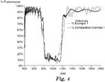
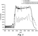
- a multilayer IR reflecting film with a 711 construction of Fig. 1 was simulated via the computer-simulation method described above.
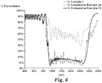
- Example 2 an optical model described as the 4x4 transfer matrix method using the Berreman algorithm was used to model a 711 constructive interference stack having 330 alternating optical layers (55 optical repeating units) of PET(polyethylene terephthalate) as polymer A and THV221 (available from 3M Dyneon, Oakdale, MN) as polymer B.
- the optical modeling predicts average reflectivity of 82% over a reflection band of 850 nm to 1850 nm.
- Figure 6 the optical modeling predicts average visible light transmission of 88% over a light transmission band of 400 nm to 750 nm.
- Comparative Example 2A an optical model described as the 4x4 transfer matrix method using the Berreman algorithm was used to model a 711 constructive interference stack having 330 alternating optical layers (55 optical repeating units) of PET(polyethylene terephthalate) as polymer A and CoPMMA (available under the tradename Altuglas 510A from Arkema, Prussia, PA) as polymer B.
- the optical modeling predicts average reflectivity of about 45 % over a reflection band of 850 nm to 1850 nm.
- the optical modeling predicts average visible light transmission of 92% over a light transmission band of 400 nm to 750 nm.
- Comparative Example 2B an optical model described as the 4x4 transfer matrix method using the Berreman algorithm was used to model a 711 constructive interference stack having 1290 alternating optical layers (215 optical repeating units) of PET (polyethylene terephthalate) as Polymer A and CoPMMA (available under the tradename Altuglas 510A from Arkema, Prussia, PA ) as Polymer B.
- PET polyethylene terephthalate
- CoPMMA available under the tradename Altuglas 510A from Arkema, Prussia, PA
- the optical modeling predicts average reflectivity of 79% over a reflection band of 850 nm to 1850 nm.
- the optical modeling predicts average visible light transmission of 91% over a light transmission band of 400 nm to 750 nm.
- Example 2 and Comparative Example 2A have the same number of optical layers.
- Example 2 exhibited superior optical properties (e.g., higher reflectivity over the reflection band of 850 nm to 1850 nm).
- Example 2 and Comparative Example 2B exhibited comparable optical power (e.g., similar reflectivity).
- Comparative Example 2 utilized much more optical layers (i.e., 215 units in Comparative Example 2B versus 55 units in Example 2), and thus had much greater thickness.
- the advantage of Example 2 to be thinner is attributed to the greater difference of refractive indices for the adjacent layers A and B (PET/THV) in Example 2 than that for PET/CoPMMA in Comparative Example 2B.
Landscapes
- Physics & Mathematics (AREA)
- General Physics & Mathematics (AREA)
- Optics & Photonics (AREA)
- Laminated Bodies (AREA)
- Optical Filters (AREA)
Applications Claiming Priority (2)
| Application Number | Priority Date | Filing Date | Title |
|---|---|---|---|
| US201662402384P | 2016-09-30 | 2016-09-30 | |
| PCT/US2017/053169 WO2018063961A1 (en) | 2016-09-30 | 2017-09-25 | Visibly transparent broadband infrared mirror films |
Publications (3)
| Publication Number | Publication Date |
|---|---|
| EP3519178A1 EP3519178A1 (en) | 2019-08-07 |
| EP3519178A4 EP3519178A4 (en) | 2020-05-27 |
| EP3519178B1 true EP3519178B1 (en) | 2022-12-28 |
Family
ID=61763586
Family Applications (1)
| Application Number | Title | Priority Date | Filing Date |
|---|---|---|---|
| EP17857246.7A Active EP3519178B1 (en) | 2016-09-30 | 2017-09-25 | Visibly transparent broadband infrared mirror films |
Country Status (5)
| Country | Link |
|---|---|
| US (1) | US11298918B2 (enExample) |
| EP (1) | EP3519178B1 (enExample) |
| JP (1) | JP7040863B2 (enExample) |
| CN (1) | CN109789667A (enExample) |
| WO (1) | WO2018063961A1 (enExample) |
Families Citing this family (23)
| Publication number | Priority date | Publication date | Assignee | Title |
|---|---|---|---|---|
| EP3693772B1 (en) * | 2017-10-03 | 2024-06-12 | Toray Industries, Inc. | Laminate film |
| JP7160091B2 (ja) * | 2018-04-19 | 2022-10-25 | Agc株式会社 | 車両用フロントガラス |
| JP7386225B2 (ja) * | 2018-07-17 | 2023-11-24 | スリーエム イノベイティブ プロパティズ カンパニー | 結晶性低屈折率層を有する赤外線反射体及び多層反射偏光子を含む光学フィルム |
| US10890700B2 (en) * | 2018-09-24 | 2021-01-12 | Apple Inc. | Electronic devices having infrared-transparent antireflection coatings |
| TWI853005B (zh) * | 2019-03-11 | 2024-08-21 | 美商3M新設資產公司 | 具有減少色彩之高效率紅外線反射膜及含其之層壓體或窗 |
| KR102219163B1 (ko) * | 2019-08-20 | 2021-02-22 | 김순훈 | 반도체 및 디스플레이 패널 제조 설비의 스테이지 구조, 상기 반도체 및 디스플레이 패널 제조 설비의 스테이지 구조에 적용되는 반도체 및 디스플레이 패널 제조 설비의 스테이지용 미러 필름 및 반도체 및 디스플레이 제조 설비용 합지 장치 |
| CN110879435B (zh) * | 2019-11-18 | 2021-08-06 | 中国科学院上海技术物理研究所 | 一种以硒化锌晶体为基底的中长波红外宽光谱分色片 |
| CN114787670B (zh) * | 2019-12-09 | 2024-07-16 | 3M创新有限公司 | 光学滤光器和光学系统 |
| US12104827B2 (en) | 2020-05-15 | 2024-10-01 | 3M Innovative Properties Company | Hybrid solar window and IR absorbing assemblies |
| CN116075527B (zh) * | 2020-08-06 | 2025-06-24 | 阿科玛股份有限公司 | 可加工的四氟乙烯共聚物 |
| JP7764389B2 (ja) * | 2020-10-09 | 2025-11-05 | 富士フイルム株式会社 | 反射フィルム、ウインドシールドガラス、および、ヘッドアップディスプレイシステム |
| CN116348792A (zh) * | 2020-10-15 | 2023-06-27 | 3M创新有限公司 | 含有具有红外吸收粘合层的多层光学制品的光学装置 |
| CN117063099A (zh) * | 2021-03-15 | 2023-11-14 | 3M创新有限公司 | 多层光学膜 |
| US20220317514A1 (en) * | 2021-04-06 | 2022-10-06 | Skc Co., Ltd. | Light reflective resin film and method of manufacturing the same |
| CN117581125A (zh) * | 2021-06-28 | 2024-02-20 | 3M创新有限公司 | 用于显示系统的光学膜 |
| CN117715749A (zh) * | 2021-07-28 | 2024-03-15 | 元平台技术有限公司 | 高模量、高导热率的双层辐射被动冷却剂 |
| WO2023026131A1 (en) * | 2021-08-23 | 2023-03-02 | 3M Innovative Properties Company | Multilayer optical film and display system |
| CN117980127A (zh) | 2021-09-22 | 2024-05-03 | 3M创新有限公司 | 聚合物膜及其制造方法 |
| US20240375337A1 (en) | 2021-09-22 | 2024-11-14 | 3M Innovative Properties Company | Polymeric Film and Method of Making Same |
| CN116382004B (zh) * | 2023-03-10 | 2025-06-10 | 哈尔滨工业大学 | 一种可见红外动态调控的智能窗 |
| CN121153358A (zh) | 2023-05-12 | 2025-12-16 | 3M创新有限公司 | 波长选择性多层制品和包括该制品的太阳能阵列 |
| WO2025149815A1 (en) * | 2024-01-11 | 2025-07-17 | 3M Innovative Properties Company | Multilayer optical films |
| NL2036941B1 (en) * | 2024-02-01 | 2025-08-12 | Autoglas D & K B V | Vehicle window laminate and method for producing the same |
Family Cites Families (22)
| Publication number | Priority date | Publication date | Assignee | Title |
|---|---|---|---|---|
| US5103337A (en) | 1990-07-24 | 1992-04-07 | The Dow Chemical Company | Infrared reflective optical interference film |
| US5360659A (en) | 1993-05-24 | 1994-11-01 | The Dow Chemical Company | Two component infrared reflecting film |
| US6498683B2 (en) | 1999-11-22 | 2002-12-24 | 3M Innovative Properties Company | Multilayer optical bodies |
| US6207260B1 (en) | 1998-01-13 | 2001-03-27 | 3M Innovative Properties Company | Multicomponent optical body |
| US6808658B2 (en) | 1998-01-13 | 2004-10-26 | 3M Innovative Properties Company | Method for making texture multilayer optical films |
| US6926952B1 (en) | 1998-01-13 | 2005-08-09 | 3M Innovative Properties Company | Anti-reflective polymer constructions and method for producing same |
| US6049419A (en) * | 1998-01-13 | 2000-04-11 | 3M Innovative Properties Co | Multilayer infrared reflecting optical body |
| US6449093B2 (en) | 1999-10-12 | 2002-09-10 | 3M Innovative Properties Company | Optical bodies made with a birefringent polymer |
| KR100905142B1 (ko) * | 2001-01-15 | 2009-06-29 | 쓰리엠 이노베이티브 프로퍼티즈 컴파니 | 가시 파장 영역에서의 높고 평활한 투과율을 가진 다층적외선 반사 필름 및 그로부터 제조된 라미네이트 제품 |
| US7019905B2 (en) * | 2003-12-30 | 2006-03-28 | 3M Innovative Properties Company | Multilayer reflector with suppression of high order reflections |
| US7345137B2 (en) | 2004-10-18 | 2008-03-18 | 3M Innovative Properties Company | Modified copolyesters and optical films including modified copolyesters |
| JP5279428B2 (ja) * | 2008-09-24 | 2013-09-04 | パナソニック株式会社 | 広域熱線カットフィルタ |
| JP4990253B2 (ja) * | 2008-09-30 | 2012-08-01 | 本田技研工業株式会社 | 多板式クラッチ |
| WO2010078289A2 (en) * | 2008-12-30 | 2010-07-08 | 3M Innovative Properties Company | Fluoropolymeric multilayer optical film and methods of making and using the same |
| CN102325650A (zh) * | 2008-12-30 | 2012-01-18 | 3M创新有限公司 | 包含含氟聚合物多层光学膜的建筑制品及其制备方法 |
| CN104999749A (zh) | 2008-12-30 | 2015-10-28 | 3M创新有限公司 | 含氟聚合物多层光学膜及其制备和使用方法 |
| US8179030B2 (en) | 2009-11-30 | 2012-05-15 | General Electric Company | Oxide multilayers for high temperature applications and lamps |
| BR112012022713A2 (pt) | 2010-03-12 | 2019-09-24 | Saint Gobain Performance Plastics Corp | dispositivo fotovoltaico, filme de múltiplas camadas e métodos de formar o mesmo |
| US9527266B2 (en) * | 2012-03-16 | 2016-12-27 | Toray Industries, Inc. | Multi-layer laminated film |
| CN104871035B (zh) * | 2012-12-20 | 2018-01-30 | 3M创新有限公司 | 制备包括层层自组装层的多层光学膜的方法以及制品 |
| US10263132B2 (en) | 2013-07-01 | 2019-04-16 | 3M Innovative Properties Company | Solar energy devices |
| CN112848602B (zh) * | 2021-02-03 | 2023-01-13 | 畅的新材料科技(上海)有限公司 | 一种双波段反射的聚酯膜 |
-
2017
- 2017-09-25 US US16/335,189 patent/US11298918B2/en active Active
- 2017-09-25 EP EP17857246.7A patent/EP3519178B1/en active Active
- 2017-09-25 JP JP2019517003A patent/JP7040863B2/ja active Active
- 2017-09-25 WO PCT/US2017/053169 patent/WO2018063961A1/en not_active Ceased
- 2017-09-25 CN CN201780060271.8A patent/CN109789667A/zh active Pending
Also Published As
| Publication number | Publication date |
|---|---|
| CN109789667A (zh) | 2019-05-21 |
| EP3519178A1 (en) | 2019-08-07 |
| WO2018063961A1 (en) | 2018-04-05 |
| JP2020500324A (ja) | 2020-01-09 |
| US20190369314A1 (en) | 2019-12-05 |
| US11298918B2 (en) | 2022-04-12 |
| EP3519178A4 (en) | 2020-05-27 |
| JP7040863B2 (ja) | 2022-03-23 |
Similar Documents
| Publication | Publication Date | Title |
|---|---|---|
| EP3519178B1 (en) | Visibly transparent broadband infrared mirror films | |
| JP6034415B2 (ja) | フッ素重合体多層光学フィルム並びにその作成方法及び使用方法 | |
| JP5676475B2 (ja) | フッ素重合体多層光学フィルム並びにその作成方法及び使用方法 | |
| EP3732514B1 (en) | Passive cooling articles having a fluoropolymer surface layer | |
| US9829604B2 (en) | Method of making multilayer optical film comprising layer-by-layer self-assembled layers and articles | |
| KR20110100663A (ko) | 플루오로중합체성 다층 광학 필름을 포함하는 건축학적 용품, 및 이를 제조하는 방법 | |
| JP2016530707A (ja) | 太陽エネルギー装置 | |
| JPWO2013099564A1 (ja) | 赤外遮蔽フィルム、これを用いた熱線反射合わせガラス、および熱線反射合わせガラスの製造方法 | |
| JPWO2013129335A1 (ja) | 近赤外反射フィルムおよびこれを用いた近赤外反射ガラス | |
| TWI677436B (zh) | 多層積層薄膜 | |
| WO2021137125A1 (en) | Ultraviolet-c radiation-protective films and methods of making the same | |
| WO2014035778A1 (en) | Reflective articles for building construction with visible light absorbing colorants | |
| EP3195024A1 (en) | Flexible and tunable anti-reflection skin | |
| KR101591196B1 (ko) | 백시트 | |
| WO2023099974A1 (en) | Semi-fluorinated thermoplastic copolymers and passive cooling articles including the same |
Legal Events
| Date | Code | Title | Description |
|---|---|---|---|
| STAA | Information on the status of an ep patent application or granted ep patent |
Free format text: STATUS: THE INTERNATIONAL PUBLICATION HAS BEEN MADE |
|
| PUAI | Public reference made under article 153(3) epc to a published international application that has entered the european phase |
Free format text: ORIGINAL CODE: 0009012 |
|
| STAA | Information on the status of an ep patent application or granted ep patent |
Free format text: STATUS: REQUEST FOR EXAMINATION WAS MADE |
|
| 17P | Request for examination filed |
Effective date: 20190328 |
|
| AK | Designated contracting states |
Kind code of ref document: A1 Designated state(s): AL AT BE BG CH CY CZ DE DK EE ES FI FR GB GR HR HU IE IS IT LI LT LU LV MC MK MT NL NO PL PT RO RS SE SI SK SM TR |
|
| AX | Request for extension of the european patent |
Extension state: BA ME |
|
| DAV | Request for validation of the european patent (deleted) | ||
| DAX | Request for extension of the european patent (deleted) | ||
| A4 | Supplementary search report drawn up and despatched |
Effective date: 20200423 |
|
| RIC1 | Information provided on ipc code assigned before grant |
Ipc: B32B 27/08 20060101ALI20200417BHEP Ipc: B32B 27/36 20060101ALI20200417BHEP Ipc: B32B 27/32 20060101ALI20200417BHEP Ipc: B32B 7/02 20190101AFI20200417BHEP Ipc: B32B 27/30 20060101ALI20200417BHEP |
|
| GRAP | Despatch of communication of intention to grant a patent |
Free format text: ORIGINAL CODE: EPIDOSNIGR1 |
|
| STAA | Information on the status of an ep patent application or granted ep patent |
Free format text: STATUS: GRANT OF PATENT IS INTENDED |
|
| INTG | Intention to grant announced |
Effective date: 20220726 |
|
| GRAS | Grant fee paid |
Free format text: ORIGINAL CODE: EPIDOSNIGR3 |
|
| GRAA | (expected) grant |
Free format text: ORIGINAL CODE: 0009210 |
|
| STAA | Information on the status of an ep patent application or granted ep patent |
Free format text: STATUS: THE PATENT HAS BEEN GRANTED |
|
| AK | Designated contracting states |
Kind code of ref document: B1 Designated state(s): AL AT BE BG CH CY CZ DE DK EE ES FI FR GB GR HR HU IE IS IT LI LT LU LV MC MK MT NL NO PL PT RO RS SE SI SK SM TR |
|
| REG | Reference to a national code |
Ref country code: GB Ref legal event code: FG4D |
|
| REG | Reference to a national code |
Ref country code: CH Ref legal event code: EP |
|
| REG | Reference to a national code |
Ref country code: DE Ref legal event code: R096 Ref document number: 602017065094 Country of ref document: DE |
|
| REG | Reference to a national code |
Ref country code: AT Ref legal event code: REF Ref document number: 1540210 Country of ref document: AT Kind code of ref document: T Effective date: 20230115 |
|
| REG | Reference to a national code |
Ref country code: IE Ref legal event code: FG4D |
|
| REG | Reference to a national code |
Ref country code: LT Ref legal event code: MG9D |
|
| PG25 | Lapsed in a contracting state [announced via postgrant information from national office to epo] |
Ref country code: SE Free format text: LAPSE BECAUSE OF FAILURE TO SUBMIT A TRANSLATION OF THE DESCRIPTION OR TO PAY THE FEE WITHIN THE PRESCRIBED TIME-LIMIT Effective date: 20221228 Ref country code: NO Free format text: LAPSE BECAUSE OF FAILURE TO SUBMIT A TRANSLATION OF THE DESCRIPTION OR TO PAY THE FEE WITHIN THE PRESCRIBED TIME-LIMIT Effective date: 20230328 Ref country code: LT Free format text: LAPSE BECAUSE OF FAILURE TO SUBMIT A TRANSLATION OF THE DESCRIPTION OR TO PAY THE FEE WITHIN THE PRESCRIBED TIME-LIMIT Effective date: 20221228 Ref country code: FI Free format text: LAPSE BECAUSE OF FAILURE TO SUBMIT A TRANSLATION OF THE DESCRIPTION OR TO PAY THE FEE WITHIN THE PRESCRIBED TIME-LIMIT Effective date: 20221228 |
|
| REG | Reference to a national code |
Ref country code: NL Ref legal event code: MP Effective date: 20221228 |
|
| REG | Reference to a national code |
Ref country code: AT Ref legal event code: MK05 Ref document number: 1540210 Country of ref document: AT Kind code of ref document: T Effective date: 20221228 |
|
| PG25 | Lapsed in a contracting state [announced via postgrant information from national office to epo] |
Ref country code: RS Free format text: LAPSE BECAUSE OF FAILURE TO SUBMIT A TRANSLATION OF THE DESCRIPTION OR TO PAY THE FEE WITHIN THE PRESCRIBED TIME-LIMIT Effective date: 20221228 Ref country code: LV Free format text: LAPSE BECAUSE OF FAILURE TO SUBMIT A TRANSLATION OF THE DESCRIPTION OR TO PAY THE FEE WITHIN THE PRESCRIBED TIME-LIMIT Effective date: 20221228 Ref country code: HR Free format text: LAPSE BECAUSE OF FAILURE TO SUBMIT A TRANSLATION OF THE DESCRIPTION OR TO PAY THE FEE WITHIN THE PRESCRIBED TIME-LIMIT Effective date: 20221228 Ref country code: GR Free format text: LAPSE BECAUSE OF FAILURE TO SUBMIT A TRANSLATION OF THE DESCRIPTION OR TO PAY THE FEE WITHIN THE PRESCRIBED TIME-LIMIT Effective date: 20230329 |
|
| PG25 | Lapsed in a contracting state [announced via postgrant information from national office to epo] |
Ref country code: NL Free format text: LAPSE BECAUSE OF FAILURE TO SUBMIT A TRANSLATION OF THE DESCRIPTION OR TO PAY THE FEE WITHIN THE PRESCRIBED TIME-LIMIT Effective date: 20221228 |
|
| P01 | Opt-out of the competence of the unified patent court (upc) registered |
Effective date: 20230530 |
|
| PG25 | Lapsed in a contracting state [announced via postgrant information from national office to epo] |
Ref country code: SM Free format text: LAPSE BECAUSE OF FAILURE TO SUBMIT A TRANSLATION OF THE DESCRIPTION OR TO PAY THE FEE WITHIN THE PRESCRIBED TIME-LIMIT Effective date: 20221228 Ref country code: RO Free format text: LAPSE BECAUSE OF FAILURE TO SUBMIT A TRANSLATION OF THE DESCRIPTION OR TO PAY THE FEE WITHIN THE PRESCRIBED TIME-LIMIT Effective date: 20221228 Ref country code: PT Free format text: LAPSE BECAUSE OF FAILURE TO SUBMIT A TRANSLATION OF THE DESCRIPTION OR TO PAY THE FEE WITHIN THE PRESCRIBED TIME-LIMIT Effective date: 20230428 Ref country code: ES Free format text: LAPSE BECAUSE OF FAILURE TO SUBMIT A TRANSLATION OF THE DESCRIPTION OR TO PAY THE FEE WITHIN THE PRESCRIBED TIME-LIMIT Effective date: 20221228 Ref country code: EE Free format text: LAPSE BECAUSE OF FAILURE TO SUBMIT A TRANSLATION OF THE DESCRIPTION OR TO PAY THE FEE WITHIN THE PRESCRIBED TIME-LIMIT Effective date: 20221228 Ref country code: CZ Free format text: LAPSE BECAUSE OF FAILURE TO SUBMIT A TRANSLATION OF THE DESCRIPTION OR TO PAY THE FEE WITHIN THE PRESCRIBED TIME-LIMIT Effective date: 20221228 Ref country code: AT Free format text: LAPSE BECAUSE OF FAILURE TO SUBMIT A TRANSLATION OF THE DESCRIPTION OR TO PAY THE FEE WITHIN THE PRESCRIBED TIME-LIMIT Effective date: 20221228 |
|
| PG25 | Lapsed in a contracting state [announced via postgrant information from national office to epo] |
Ref country code: SK Free format text: LAPSE BECAUSE OF FAILURE TO SUBMIT A TRANSLATION OF THE DESCRIPTION OR TO PAY THE FEE WITHIN THE PRESCRIBED TIME-LIMIT Effective date: 20221228 Ref country code: PL Free format text: LAPSE BECAUSE OF FAILURE TO SUBMIT A TRANSLATION OF THE DESCRIPTION OR TO PAY THE FEE WITHIN THE PRESCRIBED TIME-LIMIT Effective date: 20221228 Ref country code: IS Free format text: LAPSE BECAUSE OF FAILURE TO SUBMIT A TRANSLATION OF THE DESCRIPTION OR TO PAY THE FEE WITHIN THE PRESCRIBED TIME-LIMIT Effective date: 20230428 Ref country code: AL Free format text: LAPSE BECAUSE OF FAILURE TO SUBMIT A TRANSLATION OF THE DESCRIPTION OR TO PAY THE FEE WITHIN THE PRESCRIBED TIME-LIMIT Effective date: 20221228 |
|
| REG | Reference to a national code |
Ref country code: DE Ref legal event code: R097 Ref document number: 602017065094 Country of ref document: DE |
|
| PG25 | Lapsed in a contracting state [announced via postgrant information from national office to epo] |
Ref country code: DK Free format text: LAPSE BECAUSE OF FAILURE TO SUBMIT A TRANSLATION OF THE DESCRIPTION OR TO PAY THE FEE WITHIN THE PRESCRIBED TIME-LIMIT Effective date: 20221228 |
|
| PLBE | No opposition filed within time limit |
Free format text: ORIGINAL CODE: 0009261 |
|
| STAA | Information on the status of an ep patent application or granted ep patent |
Free format text: STATUS: NO OPPOSITION FILED WITHIN TIME LIMIT |
|
| 26N | No opposition filed |
Effective date: 20230929 |
|
| PG25 | Lapsed in a contracting state [announced via postgrant information from national office to epo] |
Ref country code: SI Free format text: LAPSE BECAUSE OF FAILURE TO SUBMIT A TRANSLATION OF THE DESCRIPTION OR TO PAY THE FEE WITHIN THE PRESCRIBED TIME-LIMIT Effective date: 20221228 |
|
| REG | Reference to a national code |
Ref country code: CH Ref legal event code: PL |
|
| PG25 | Lapsed in a contracting state [announced via postgrant information from national office to epo] |
Ref country code: LU Free format text: LAPSE BECAUSE OF NON-PAYMENT OF DUE FEES Effective date: 20230925 |
|
| REG | Reference to a national code |
Ref country code: BE Ref legal event code: MM Effective date: 20230930 |
|
| GBPC | Gb: european patent ceased through non-payment of renewal fee |
Effective date: 20230925 |
|
| PG25 | Lapsed in a contracting state [announced via postgrant information from national office to epo] |
Ref country code: LU Free format text: LAPSE BECAUSE OF NON-PAYMENT OF DUE FEES Effective date: 20230925 Ref country code: IT Free format text: LAPSE BECAUSE OF FAILURE TO SUBMIT A TRANSLATION OF THE DESCRIPTION OR TO PAY THE FEE WITHIN THE PRESCRIBED TIME-LIMIT Effective date: 20221228 Ref country code: MC Free format text: LAPSE BECAUSE OF FAILURE TO SUBMIT A TRANSLATION OF THE DESCRIPTION OR TO PAY THE FEE WITHIN THE PRESCRIBED TIME-LIMIT Effective date: 20221228 |
|
| REG | Reference to a national code |
Ref country code: IE Ref legal event code: MM4A |
|
| PG25 | Lapsed in a contracting state [announced via postgrant information from national office to epo] |
Ref country code: IE Free format text: LAPSE BECAUSE OF NON-PAYMENT OF DUE FEES Effective date: 20230925 |
|
| PG25 | Lapsed in a contracting state [announced via postgrant information from national office to epo] |
Ref country code: GB Free format text: LAPSE BECAUSE OF NON-PAYMENT OF DUE FEES Effective date: 20230925 |
|
| PG25 | Lapsed in a contracting state [announced via postgrant information from national office to epo] |
Ref country code: CH Free format text: LAPSE BECAUSE OF NON-PAYMENT OF DUE FEES Effective date: 20230930 |
|
| PG25 | Lapsed in a contracting state [announced via postgrant information from national office to epo] |
Ref country code: IE Free format text: LAPSE BECAUSE OF NON-PAYMENT OF DUE FEES Effective date: 20230925 Ref country code: GB Free format text: LAPSE BECAUSE OF NON-PAYMENT OF DUE FEES Effective date: 20230925 Ref country code: FR Free format text: LAPSE BECAUSE OF NON-PAYMENT OF DUE FEES Effective date: 20230930 Ref country code: CH Free format text: LAPSE BECAUSE OF NON-PAYMENT OF DUE FEES Effective date: 20230930 |
|
| PG25 | Lapsed in a contracting state [announced via postgrant information from national office to epo] |
Ref country code: BE Free format text: LAPSE BECAUSE OF NON-PAYMENT OF DUE FEES Effective date: 20230930 |
|
| PG25 | Lapsed in a contracting state [announced via postgrant information from national office to epo] |
Ref country code: BG Free format text: LAPSE BECAUSE OF FAILURE TO SUBMIT A TRANSLATION OF THE DESCRIPTION OR TO PAY THE FEE WITHIN THE PRESCRIBED TIME-LIMIT Effective date: 20221228 |
|
| PG25 | Lapsed in a contracting state [announced via postgrant information from national office to epo] |
Ref country code: BG Free format text: LAPSE BECAUSE OF FAILURE TO SUBMIT A TRANSLATION OF THE DESCRIPTION OR TO PAY THE FEE WITHIN THE PRESCRIBED TIME-LIMIT Effective date: 20221228 |
|
| PG25 | Lapsed in a contracting state [announced via postgrant information from national office to epo] |
Ref country code: CY Free format text: LAPSE BECAUSE OF FAILURE TO SUBMIT A TRANSLATION OF THE DESCRIPTION OR TO PAY THE FEE WITHIN THE PRESCRIBED TIME-LIMIT; INVALID AB INITIO Effective date: 20170925 |
|
| PG25 | Lapsed in a contracting state [announced via postgrant information from national office to epo] |
Ref country code: HU Free format text: LAPSE BECAUSE OF FAILURE TO SUBMIT A TRANSLATION OF THE DESCRIPTION OR TO PAY THE FEE WITHIN THE PRESCRIBED TIME-LIMIT; INVALID AB INITIO Effective date: 20170925 |
|
| PGFP | Annual fee paid to national office [announced via postgrant information from national office to epo] |
Ref country code: DE Payment date: 20250820 Year of fee payment: 9 |
|
| PG25 | Lapsed in a contracting state [announced via postgrant information from national office to epo] |
Ref country code: TR Free format text: LAPSE BECAUSE OF FAILURE TO SUBMIT A TRANSLATION OF THE DESCRIPTION OR TO PAY THE FEE WITHIN THE PRESCRIBED TIME-LIMIT Effective date: 20221228 |