EP3518350A1 - Elektrische steckverbindung - Google Patents
Elektrische steckverbindung Download PDFInfo
- Publication number
- EP3518350A1 EP3518350A1 EP19153532.7A EP19153532A EP3518350A1 EP 3518350 A1 EP3518350 A1 EP 3518350A1 EP 19153532 A EP19153532 A EP 19153532A EP 3518350 A1 EP3518350 A1 EP 3518350A1
- Authority
- EP
- European Patent Office
- Prior art keywords
- connector
- plug connection
- unlocking
- plug
- unlocking element
- Prior art date
- Legal status (The legal status is an assumption and is not a legal conclusion. Google has not performed a legal analysis and makes no representation as to the accuracy of the status listed.)
- Granted
Links
Images
Classifications
-
- H—ELECTRICITY
- H01—ELECTRIC ELEMENTS
- H01R—ELECTRICALLY-CONDUCTIVE CONNECTIONS; STRUCTURAL ASSOCIATIONS OF A PLURALITY OF MUTUALLY-INSULATED ELECTRICAL CONNECTING ELEMENTS; COUPLING DEVICES; CURRENT COLLECTORS
- H01R13/00—Details of coupling devices of the kinds covered by groups H01R12/70 or H01R24/00 - H01R33/00
- H01R13/46—Bases; Cases
-
- H—ELECTRICITY
- H01—ELECTRIC ELEMENTS
- H01R—ELECTRICALLY-CONDUCTIVE CONNECTIONS; STRUCTURAL ASSOCIATIONS OF A PLURALITY OF MUTUALLY-INSULATED ELECTRICAL CONNECTING ELEMENTS; COUPLING DEVICES; CURRENT COLLECTORS
- H01R13/00—Details of coupling devices of the kinds covered by groups H01R12/70 or H01R24/00 - H01R33/00
- H01R13/62—Means for facilitating engagement or disengagement of coupling parts or for holding them in engagement
- H01R13/629—Additional means for facilitating engagement or disengagement of coupling parts, e.g. aligning or guiding means, levers, gas pressure electrical locking indicators, manufacturing tolerances
- H01R13/633—Additional means for facilitating engagement or disengagement of coupling parts, e.g. aligning or guiding means, levers, gas pressure electrical locking indicators, manufacturing tolerances for disengagement only
-
- H—ELECTRICITY
- H01—ELECTRIC ELEMENTS
- H01R—ELECTRICALLY-CONDUCTIVE CONNECTIONS; STRUCTURAL ASSOCIATIONS OF A PLURALITY OF MUTUALLY-INSULATED ELECTRICAL CONNECTING ELEMENTS; COUPLING DEVICES; CURRENT COLLECTORS
- H01R13/00—Details of coupling devices of the kinds covered by groups H01R12/70 or H01R24/00 - H01R33/00
- H01R13/62—Means for facilitating engagement or disengagement of coupling parts or for holding them in engagement
- H01R13/627—Snap or like fastening
- H01R13/6271—Latching means integral with the housing
- H01R13/6272—Latching means integral with the housing comprising a single latching arm
-
- H—ELECTRICITY
- H01—ELECTRIC ELEMENTS
- H01R—ELECTRICALLY-CONDUCTIVE CONNECTIONS; STRUCTURAL ASSOCIATIONS OF A PLURALITY OF MUTUALLY-INSULATED ELECTRICAL CONNECTING ELEMENTS; COUPLING DEVICES; CURRENT COLLECTORS
- H01R13/00—Details of coupling devices of the kinds covered by groups H01R12/70 or H01R24/00 - H01R33/00
- H01R13/62—Means for facilitating engagement or disengagement of coupling parts or for holding them in engagement
- H01R13/629—Additional means for facilitating engagement or disengagement of coupling parts, e.g. aligning or guiding means, levers, gas pressure electrical locking indicators, manufacturing tolerances
- H01R13/62933—Comprising exclusively pivoting lever
-
- H—ELECTRICITY
- H01—ELECTRIC ELEMENTS
- H01R—ELECTRICALLY-CONDUCTIVE CONNECTIONS; STRUCTURAL ASSOCIATIONS OF A PLURALITY OF MUTUALLY-INSULATED ELECTRICAL CONNECTING ELEMENTS; COUPLING DEVICES; CURRENT COLLECTORS
- H01R13/00—Details of coupling devices of the kinds covered by groups H01R12/70 or H01R24/00 - H01R33/00
- H01R13/62—Means for facilitating engagement or disengagement of coupling parts or for holding them in engagement
- H01R13/629—Additional means for facilitating engagement or disengagement of coupling parts, e.g. aligning or guiding means, levers, gas pressure electrical locking indicators, manufacturing tolerances
- H01R13/633—Additional means for facilitating engagement or disengagement of coupling parts, e.g. aligning or guiding means, levers, gas pressure electrical locking indicators, manufacturing tolerances for disengagement only
- H01R13/6335—Additional means for facilitating engagement or disengagement of coupling parts, e.g. aligning or guiding means, levers, gas pressure electrical locking indicators, manufacturing tolerances for disengagement only comprising a handle
-
- H—ELECTRICITY
- H01—ELECTRIC ELEMENTS
- H01R—ELECTRICALLY-CONDUCTIVE CONNECTIONS; STRUCTURAL ASSOCIATIONS OF A PLURALITY OF MUTUALLY-INSULATED ELECTRICAL CONNECTING ELEMENTS; COUPLING DEVICES; CURRENT COLLECTORS
- H01R13/00—Details of coupling devices of the kinds covered by groups H01R12/70 or H01R24/00 - H01R33/00
- H01R13/62—Means for facilitating engagement or disengagement of coupling parts or for holding them in engagement
- H01R13/629—Additional means for facilitating engagement or disengagement of coupling parts, e.g. aligning or guiding means, levers, gas pressure electrical locking indicators, manufacturing tolerances
- H01R13/633—Additional means for facilitating engagement or disengagement of coupling parts, e.g. aligning or guiding means, levers, gas pressure electrical locking indicators, manufacturing tolerances for disengagement only
- H01R13/635—Additional means for facilitating engagement or disengagement of coupling parts, e.g. aligning or guiding means, levers, gas pressure electrical locking indicators, manufacturing tolerances for disengagement only by mechanical pressure, e.g. spring force
-
- H—ELECTRICITY
- H01—ELECTRIC ELEMENTS
- H01R—ELECTRICALLY-CONDUCTIVE CONNECTIONS; STRUCTURAL ASSOCIATIONS OF A PLURALITY OF MUTUALLY-INSULATED ELECTRICAL CONNECTING ELEMENTS; COUPLING DEVICES; CURRENT COLLECTORS
- H01R24/00—Two-part coupling devices, or either of their cooperating parts, characterised by their overall structure
-
- H—ELECTRICITY
- H01—ELECTRIC ELEMENTS
- H01R—ELECTRICALLY-CONDUCTIVE CONNECTIONS; STRUCTURAL ASSOCIATIONS OF A PLURALITY OF MUTUALLY-INSULATED ELECTRICAL CONNECTING ELEMENTS; COUPLING DEVICES; CURRENT COLLECTORS
- H01R4/00—Electrically-conductive connections between two or more conductive members in direct contact, i.e. touching one another; Means for effecting or maintaining such contact; Electrically-conductive connections having two or more spaced connecting locations for conductors and using contact members penetrating insulation
- H01R4/28—Clamped connections, spring connections
- H01R4/48—Clamped connections, spring connections utilising a spring, clip, or other resilient member
- H01R4/4809—Clamped connections, spring connections utilising a spring, clip, or other resilient member using a leaf spring to bias the conductor toward the busbar
- H01R4/48185—Clamped connections, spring connections utilising a spring, clip, or other resilient member using a leaf spring to bias the conductor toward the busbar adapted for axial insertion of a wire end
- H01R4/4819—Clamped connections, spring connections utilising a spring, clip, or other resilient member using a leaf spring to bias the conductor toward the busbar adapted for axial insertion of a wire end the spring shape allowing insertion of the conductor end when the spring is unbiased
- H01R4/4821—Single-blade spring
-
- H—ELECTRICITY
- H01—ELECTRIC ELEMENTS
- H01R—ELECTRICALLY-CONDUCTIVE CONNECTIONS; STRUCTURAL ASSOCIATIONS OF A PLURALITY OF MUTUALLY-INSULATED ELECTRICAL CONNECTING ELEMENTS; COUPLING DEVICES; CURRENT COLLECTORS
- H01R11/00—Individual connecting elements providing two or more spaced connecting locations for conductive members which are, or may be, thereby interconnected, e.g. end pieces for wires or cables supported by the wire or cable and having means for facilitating electrical connection to some other wire, terminal, or conductive member, blocks of binding posts
- H01R11/03—Individual connecting elements providing two or more spaced connecting locations for conductive members which are, or may be, thereby interconnected, e.g. end pieces for wires or cables supported by the wire or cable and having means for facilitating electrical connection to some other wire, terminal, or conductive member, blocks of binding posts characterised by the relationship between the connecting locations
- H01R11/05—Individual connecting elements providing two or more spaced connecting locations for conductive members which are, or may be, thereby interconnected, e.g. end pieces for wires or cables supported by the wire or cable and having means for facilitating electrical connection to some other wire, terminal, or conductive member, blocks of binding posts characterised by the relationship between the connecting locations the connecting locations having different types of direct connections
-
- H—ELECTRICITY
- H01—ELECTRIC ELEMENTS
- H01R—ELECTRICALLY-CONDUCTIVE CONNECTIONS; STRUCTURAL ASSOCIATIONS OF A PLURALITY OF MUTUALLY-INSULATED ELECTRICAL CONNECTING ELEMENTS; COUPLING DEVICES; CURRENT COLLECTORS
- H01R13/00—Details of coupling devices of the kinds covered by groups H01R12/70 or H01R24/00 - H01R33/00
- H01R13/02—Contact members
- H01R13/10—Sockets for co-operation with pins or blades
- H01R13/11—Resilient sockets
- H01R13/112—Resilient sockets forked sockets having two legs
-
- H—ELECTRICITY
- H01—ELECTRIC ELEMENTS
- H01R—ELECTRICALLY-CONDUCTIVE CONNECTIONS; STRUCTURAL ASSOCIATIONS OF A PLURALITY OF MUTUALLY-INSULATED ELECTRICAL CONNECTING ELEMENTS; COUPLING DEVICES; CURRENT COLLECTORS
- H01R4/00—Electrically-conductive connections between two or more conductive members in direct contact, i.e. touching one another; Means for effecting or maintaining such contact; Electrically-conductive connections having two or more spaced connecting locations for conductors and using contact members penetrating insulation
- H01R4/28—Clamped connections, spring connections
- H01R4/48—Clamped connections, spring connections utilising a spring, clip, or other resilient member
- H01R4/4809—Clamped connections, spring connections utilising a spring, clip, or other resilient member using a leaf spring to bias the conductor toward the busbar
- H01R4/4828—Spring-activating arrangements mounted on or integrally formed with the spring housing
- H01R4/483—Pivoting arrangements, e.g. lever pushing on the spring
-
- H—ELECTRICITY
- H01—ELECTRIC ELEMENTS
- H01R—ELECTRICALLY-CONDUCTIVE CONNECTIONS; STRUCTURAL ASSOCIATIONS OF A PLURALITY OF MUTUALLY-INSULATED ELECTRICAL CONNECTING ELEMENTS; COUPLING DEVICES; CURRENT COLLECTORS
- H01R4/00—Electrically-conductive connections between two or more conductive members in direct contact, i.e. touching one another; Means for effecting or maintaining such contact; Electrically-conductive connections having two or more spaced connecting locations for conductors and using contact members penetrating insulation
- H01R4/28—Clamped connections, spring connections
- H01R4/48—Clamped connections, spring connections utilising a spring, clip, or other resilient member
- H01R4/4809—Clamped connections, spring connections utilising a spring, clip, or other resilient member using a leaf spring to bias the conductor toward the busbar
- H01R4/4846—Busbar details
- H01R4/4852—Means for improving the contact with the conductor, e.g. uneven wire-receiving surface
Definitions
- the invention relates to an electrical connector having a connector and a counterpart associated mating connector, wherein the connector with the mating connector for making an electrical connector in a plug-in direction is mated, wherein the connector has a first locking device and the mating connector a second locking device wherein the connector is fixable to the mating connector by a positive connection of the first locking device with the second locking device and in an unlocking this fixation by manual actuation of a connector or on the mating connector movably mounted unlocking is releasably by the unlocking manually on manual operation the first and / or the second locking device acts.
- a generic electrical connector is from the DE 10 2011 102 715 A1 known.
- the invention has for its object to further develop such an electrical connector with respect to the locking mechanism.
- the unlocking is pivotally mounted about a pivot axis on the connector or the mating connector, wherein the unlocking on one side of the pivot axis a manual operation area, which is set up for manual operation of the unlocking is, and on the other side of the pivot axis has a projecting actuating lug, by which the first and / or the second locking device is mechanically deflected in the unlocking.
- the manual operating range of the unlocking element can optionally be operated directly manually, for example with a finger, or indirectly via a tool, for example by a screwdriver.
- Another advantage of the invention is that an electrical connector with a small space can be realized and therefore is easily miniaturized.
- an electrical connector also allows the provision of a spring terminal connection, for example in the connector or in the mating connector, or in both elements connector and mating connector.
- the connector may have one or more plug contacts, e.g. male and / or female plug contacts, also mixed, e.g. in the form of contact pins, contact blades or fork contacts.
- the mating connector may also have plug contacts, which are formed in a comparable manner as the plug contacts of the connector, only in each case as a counterpart thereto.
- the unlocking element can be actuated in an actuating direction which is arranged at an angle to the plugging direction of the plug connection. Accordingly, there is an angle between the actuating direction and the plug-in direction, for example an angle of at least 40 °.
- the angle can in particular also be a substantially right angle.
- the unlocking element can be actuated particularly easily and conveniently manually.
- the plug-in direction of the connector defines a direction in which the connector is mated with the mating connector, which is usually a Moving direction corresponds, in which the mating face of the connector is moved to the mating face of the mating connector and the connector is then connected to the mating connector.
- these locking devices may comprise respective locking elements, which are designed as form-fitting counterparts to one another, e.g. in the form of locking elements, Rastanformungen, locking tabs or locking recesses.
- the fixation of the connector to the mating connector can be done without special manual operation of one of the locking devices, e.g. in that the first locking device and the second locking device automatically interlock positively when the connector is mated with the mating connector.
- an elastic locking element can be automatically deflected during mating, so that after reaching the final connection position of the connector on the mating connector this elastic locking element can automatically snap back and thereby the positive connection of the first locking device is made with the second locking device in the sense of locking.
- At least one housing component of the connector or the mating connector is expandable in the unlocking by the unlocking.
- a locking tab which is arranged on the housing component, can be widened in the sense of being levered open.
- the unlocking element can therefore be designed as a pivotable lever or a rocker.
- the unlocking element may comprise one or more bearing elements, via which a defined bearing axis is fixed, which at the same time forms the pivot axis of the unlocking element.
- the bearing elements can each be laterally projecting bearing pins formed on the unlocking element, which engage in corresponding pin receptacles on the housing member to which the unlocking element is attached.
- That component of connector and mating connector which has the unlocking element, at least one spring terminal connection for clamping an electrical conductor to a clamping point by means of spring force, the spring terminal connection by an actuating element of this component from a closed position in an open position is movable. This allows a simple and comfortable connection of an electrical conductor and also a secure permanent fixation of the electrical conductor at the terminal point.
- the other component of connector and mating connector which does not have the unlocking, may have a spring terminal connection for clamping an electrical conductor at a clamping point by means of spring force.
- the closed position of the spring terminal connection can correspond with a closed position of the actuating element.
- the open position of the spring force terminal connection may correspond to an open position of the actuating element.
- the actuator may e.g. be designed as an actuating lever which is pivotally mounted on the connector or the mating connector.
- the unlocking element in particular the manual actuating region of the unlocking element or a stop region of the unlocking element, forms a mechanical stop for the actuating element in the open position.
- the stop area can be arranged, for example, on the manual operating area. In this way, an excessive actuation of the actuating element in Counteracted direction of the open position, without additional components for such a travel limit are required.
- the unlocking element is blocked by the actuating element against manual actuation when the actuating element is in the open position.
- This has the advantage that in the open position of the actuating element, the assembled components plug connector and mating connector can not be detached from each other.
- the actuating element must first be moved in the direction of the closed position. The blocking of the unlocking element may already be canceled before the manual actuator has fully reached the closed position.
- the unlocking element is arranged substantially centrally in the region of plug contacts of the connector and / or the mating connector.
- the unlocking can be arranged at a central location of the connector or the mating connector, so that it can be easily detected when gripping the connector or the mating connector and can be operated with one hand.
- the spring terminal connection comprises a busbar and a clamping spring, wherein the clamping spring is mounted self-supporting on the busbar.
- the clamping spring is mounted self-supporting on the busbar.
- the busbar and / or the clamping spring is formed integrally with at least a part of a plug connection contact of the connector or mating connector.
- the plug connection contact can be part of that component of plug connector and mating connector, which has the unlocking element. In this way, the plug connection contact can be provided in a technically favorable manner.
- the conductor insertion direction of the spring terminal connection is substantially parallel or identical to the insertion direction. In this way, a compact, small-sized plug connection can be realized.
- the clamping spring has a clamping leg for clamping an electrical conductor, wherein a spring bow connects to the clamping leg and to the spring bow a plant leg, which is attached to the busbar.
- the clamping spring may, for example, have a loop shape.
- the spring bow from the plant leg from opposite the Leitereinstecktement fort Vietnamese.
- an electrical conductor is inserted in the conductor insertion in the spring terminal connection, this is guided in the direction of the spring bow and finally passed by the spring bow.
- the spring bow can then be located in a region between a handle region of the actuating element on which the actuating element is to be operated manually, e.g. a lever handle, and the inserted electrical conductor.
- the plant leg is bent several times with at least two bent in opposite bending direction areas. This also promotes the compact design of the electrical connector. It is possible to be more compact Design to accommodate a lever actuation in the housing of the connector or the mating connector.
- the bearing limb in particular the region of the bearing limb bent several times, extends through a free space surrounded by the actuating element.
- the actuating element with, for example, laterally extending from the clamping spring cheeks engage around the clamping spring.
- the actuating element can be compared with the force of the clamping leg on the busbar and / or a part of the clamping spring, e.g. an extended portion of the abutment leg, be supported, e.g. by the lateral cheeks rest on a corresponding support point of the busbar and / or a part of the clamping spring.
- the indefinite term "a” does not mean a number word. So if, for example, If a component is mentioned, this is to be interpreted in the sense of "at least one component”. Insofar as angle data are given in degrees, these refer to a circular dimension of 360 degrees (360 °).
- the connector 1 has a housing 2, for example, an insulating material.
- the housing 2 has a conductor insertion opening 20. Through the conductor insertion opening 20 For example, an electrical conductor can be inserted in a conductor insertion direction L and clamped to a clamping point to be described below.
- the connector 1 also has a Federkraftklemman gleich with a busbar 3 and a clamping spring 4, which are arranged as an electrical contact insert in the housing 2.
- the clamping spring 4 has an abutment leg 40, which is fastened with an end-side, essentially vertical to the conductor insertion direction L extending end portion 41 on a likewise substantially vertical to the conductor insertion direction L extending holding portion 31 of the busbar 3. In this way, the clamping spring 4 is fixed to the busbar 3.
- the plant leg 40 extends over a multiply bent region 42 toward a spring bow 43, to which a clamping leg 44 of the clamping spring 4 is connected.
- the clamping leg 44 terminates with a clamping tongue 45 which, together with a conductor connection region 30 of the busbar 3, forms a clamping point for clamping an electrical conductor.
- the connector 1 also has an actuating element 5 in the form of a pivotable actuating lever.
- the actuating element 5 has a grip region 50, on which a user can manually actuate the actuating element 5.
- the actuator 5 is used to open the nip in order to facilitate the insertion of an electrical conductor or to allow the removal of an already clamped electrical conductor.
- the actuating element 5 has a spring driver 52, which can press against a region of the clamping leg 44 and in this way can deflect the clamping leg 44 including the clamping tongue 45.
- the FIG. 1 shows in solid lines the clamping spring with closed nip. In this case, the actuating element is in the closed position, which is also shown in solid lines.
- the FIG. 1 shows in solid lines the clamping spring with closed nip. In this case, the actuating element is in the closed position, which is also shown in solid lines.
- FIG. 1 also shows the actuator in the open position, which is shown by dotted lines.
- the clamping limb 44 is deflected upward by the spring driver 52, which is indicated by the reference numeral 44a and the representation of the clamping leg in dashed lines is marked.
- the handle portion 50 is shown in this case by the reference numeral 50a.
- the connector 1 also has in a protruding toward the mating connector 10 housing portion 21 a plug connection contact 33, which may be, for example, realized by two fork legs and accordingly forms a fork contact.
- the fork legs of the plug connection contact 33 may be formed integrally with the bus bar 3, e.g. in that the fork legs 33 are connected to one another via a vertical section 32 of the busbar material and these in turn are connected to the holding section 31.
- the mating connector 10 has its own housing 11, e.g. made of insulating material.
- the mating connector 10 has a plug connection contact 12, which is designed as a counterpart to the plug connection contact 33, e.g. as a knife contact or as a pin contact.
- This plug connection contact 12 can be inserted through an insertion opening 22 in the housing region 21 into the plug connector 1 and is received between the fork legs of the plug connection contact 33.
- the connector 1 can accordingly be plugged together in a plug-in direction S with the mating connector 10.
- a positive connection via a first locking device 23 of the connector and a second locking device 13 of the mating connector is provided.
- the first locking device 23, the second locking device 13 engage behind a form-fitting or snap behind it (in the sense of locking elements).
- the second locking device 13 may, for example, be arranged on a flexible tongue of the housing 11.
- the unlocking element 6 is fixed to the connector 1, e.g. on the outside of the housing 2.
- the unlocking element 6 is designed as a pivotable, about an axis of rotation rotatable unlocking, which is similar to a rocker movable.
- the unlocking element 6 has a manual operating region 60, which serves for the manual actuation of the unlocking element 6.
- the unlocking element 6 is connected via a bearing axis, e.g. in the form of laterally projecting bearing pin 62, rotatably mounted on the housing 2. At the other end, i.e.
- the unlocking element 6 ends with a projecting actuating lug 61 which engages under a portion of the housing 11 of the mating connector 10. If the unlocking element 6 is actuated on the manual operating region 60 in an actuating direction B, it performs a clockwise movement, which is limited by a stop surface 24 of the housing 2. Here, the actuating lug 61 lifts the second locking device 13 having part of the housing 11, so that the fixation is canceled.
- the unlocking element 6 has a stop element 63 which serves as a stop and travel limit for the actuating element 5.
- the actuating element 5 can only be moved in the direction of the open position until it comes to rest on the stop element 63.
Landscapes
- Details Of Connecting Devices For Male And Female Coupling (AREA)
Abstract
Description
- Die Erfindung betrifft eine elektrische Steckverbindung, die einen Steckverbinder und einen dem Steckverbinder als Gegenstück zugeordneten Gegensteckverbinder aufweist, wobei der Steckverbinder mit dem Gegensteckverbinder zur Herstellung einer elektrischen Steckverbindung in einer Steckrichtung zusammensteckbar ist, wobei der Steckverbinder eine erste Verriegelungseinrichtung aufweist und der Gegensteckverbinder eine zweite Verriegelungseinrichtung aufweist, wobei der Steckverbinder an dem Gegensteckverbinder durch eine formschlüssige Verbindung der ersten Verriegelungseinrichtung mit der zweiten Verriegelungseinrichtung fixierbar ist und bei einem Entriegelungsvorgang diese Fixierung durch manuelle Betätigung eines am Steckverbinder oder am Gegensteckverbinder beweglich befestigten Entriegelungselementes lösbar ist, indem das Entriegelungselement bei manueller Betätigung mechanisch auf die erste und/oder die zweite Verriegelungseinrichtung einwirkt.
- Eine gattungsgemäße elektrische Steckverbindung ist aus der
DE 10 2011 102 715 A1 bekannt. - Der Erfindung liegt die Aufgabe zugrunde, eine solche elektrische Steckverbindung hinsichtlich des Verriegelungsmechanismus weiter zu entwickeln.
- Diese Aufgabe wird bei der elektrischen Steckverbindung der eingangs genannten Art dadurch gelöst, dass das Entriegelungselement um eine Verschwenkachse verschwenkbar an dem Steckverbinder oder dem Gegensteckverbinder befestigt ist, wobei das Entriegelungselement auf einer Seite der Verschwenkachse einen manuellen Betätigungsbereich, der zur manuellen Betätigung des Entriegelungselementes eingerichtet ist, und auf der anderen Seite der Verschwenkachse eine abragende Betätigungsnase aufweist, durch die die erste und/oder die zweite Verriegelungseinrichtung bei dem Entriegelungsvorgang mechanisch auslenkbar ist. Hierdurch lässt sich eine sichere Verriegelung der Steckverbinderteile aneinander bei zugleich einfacher Handhabung zum Lösen der Fixierung realisieren. Insbesondere ist eine einhändige Betätigung zum Lösen der Fixierung möglich. Der manuelle Betätigungsbereich des Entriegelungselementes kann wahlweise direkt manuell betätigt werden, z.B. mit einem Finger, oder indirekt über ein Werkzeug, z.B. durch einen Schraubendreher.
- Ein weiterer Vorteil der Erfindung besteht darin, dass eine elektrische Steckverbindung mit geringem Bauraum realisiert werden kann und daher gut miniaturisierbar ist. Zusätzlich erlaubt eine solche elektrische Steckverbindung auch das Bereitstellen eines Federkraftklemmanschlusses, bspw. in dem Steckverbinder oder in dem Gegensteckverbinder, oder in beiden Elementen Steckverbinder und Gegensteckverbinder.
- Der Steckverbinder kann einen oder mehrere Steckkontakte aufweisen, z.B. männliche und/oder weibliche Steckkontakte, auch gemischt, z.B. in Form von Kontaktstiften, Kontaktmessern oder Gabelkontakten. Der Gegensteckverbinder kann ebenfalls Steckkontakte aufweisen, die in vergleichbarer Weise ausgebildet sind wie die Steckkontakte des Steckverbinders, nur jeweils als Gegenstück dazu.
- Gemäß einer vorteilhaften Weiterbildung der Erfindung ist vorgesehen, dass das Entriegelungselement in einer Betätigungsrichtung betätigbar ist, die winklig zur Steckrichtung der Steckverbindung angeordnet ist. Dementsprechend liegt ein Winkel zwischen der Betätigungsrichtung und der Steckrichtung vor, bspw. ein Winkel von wenigstens 40°. Der Winkel kann insbesondere auch ein im Wesentlichen rechter Winkel sein. Hierdurch lässt sich das Entriegelungselement besonders einfach und komfortabel manuell betätigen.
- Die Steckrichtung der Steckverbindung definiert eine Richtung, in der der Steckverbinder mit dem Gegensteckverbinder zusammensteckbar ist, was in der Regel einer Bewegungsrichtung entspricht, bei der das Steckgesicht des Steckverbinders auf das Steckgesicht des Gegensteckverbinders zu bewegt wird und der Steckverbinder mit dem Gegensteckverbinder dann verbunden wird.
- Zur Bereitstellung der formschlüssigen Verbindung der ersten Verriegelungseinrichtung mit der zweiten Verriegelungseinrichtung können diese Verriegelungseinrichtungen jeweilige Verriegelungselemente aufweisen, die als formschlüssige Gegenstücke zueinander ausgebildet sind, z.B. in Form von Rastelementen, Rastanformungen, Rastlaschen oder Rastaussparungen.
- Die Fixierung des Steckverbinders an dem Gegensteckverbinder kann ohne besondere manuelle Betätigung einer der Verriegelungseinrichtungen erfolgen, z.B. dadurch, dass die erste Verriegelungseinrichtung und die zweite Verriegelungseinrichtung beim Zusammenstecken des Steckverbinders mit dem Gegensteckverbinder automatisch formschlüssig ineinandergreifen. Hierbei kann beispielsweise ein elastisches Verriegelungselement beim Zusammenstecken automatisch ausgelenkt werden, sodass nach Erreichen der endgültigen Verbindungsposition des Steckverbinders an dem Gegensteckverbinder dieses elastische Verriegelungselement selbsttätig zurückschnappen kann und hierdurch die formschlüssige Verbindung der ersten Verriegelungseinrichtung mit der zweiten Verriegelungseinrichtung im Sinne einer Verrastung hergestellt wird.
- Gemäß einer vorteilhaften Weiterbildung der Erfindung ist vorgesehen, dass wenigstens ein Gehäusebauteil des Steckverbinders oder des Gegensteckverbinders bei dem Entriegelungsvorgang durch das Entriegelungselement aufweitbar ist. Beispielsweise kann auf diese Weise eine Verriegelungslasche, die an dem Gehäusebauteil angeordnet ist, aufgeweitet im Sinne von aufgehebelt werden.
- Das Entriegelungselement kann daher wie ein verschwenkbarer Hebel oder eine Wippe ausgebildet sein. Hierfür kann das Entriegelungselement eines oder mehrere Lagerungselemente aufweisen, über die eine definierte Lagerachse festgelegt ist, die zugleich die Verschwenkachse des Entriegelungselementes bildet. Beispielsweise können am Entriegelungselement jeweils seitlich abragende Lagerzapfen angeformt sein, die in entsprechende Zapfenaufnahmen am Gehäusebauteil eingreifen, an dem das Entriegelungselement befestigt ist.
- Gemäß einer vorteilhaften Weiterbildung der Erfindung ist vorgesehen, dass dasjenige Bauteil von Steckverbinder und Gegensteckverbinder, das das Entriegelungselement aufweist, wenigstens einen Federkraftklemmanschluss zum Anklemmen eines elektrischen Leiters an einer Klemmstelle mittels Federkraft aufweist, wobei der Federkraftklemmanschluss durch ein Betätigungselement dieses Bauteils von einer geschlossenen Stellung in eine geöffnete Stellung bewegbar ist. Dies erlaubt ein einfaches und komfortables Anschließen eines elektrischen Leiters und zudem eine sichere dauerhafte Fixierung des elektrischen Leiters an der Klemmstelle.
- Auch das andere Bauteil von Steckverbinder und Gegensteckverbinder, das nicht das Entriegelungselement aufweist, kann einen Federkraftklemmanschluss zum Anklemmen eines elektrischen Leiters an einer Klemmstelle mittels Federkraft aufweisen.
- Die geschlossene Stellung des Federkraftklemmanschlusses kann dabei mit einer geschlossenen Stellung des Betätigungselementes korrespondieren. Die geöffnete Stellung des Federkraftklemmanschlusses kann mit einer geöffneten Stellung des Betätigungselementes korrespondieren. Das Betätigungselement kann z.B. als Betätigungshebel ausgebildet sein, der verschwenkbar am Steckverbinder oder am Gegensteckverbinder befestigt ist.
- Gemäß einer vorteilhaften Weiterbildung der Erfindung ist vorgesehen, dass das Entriegelungselement, insbesondere der manuelle Betätigungsbereich des Entriegelungselementes oder ein Anschlagbereich des Entriegelungselementes, einen mechanischen Anschlag für das Betätigungselement in der geöffneten Stellung bildet. Der Anschlagbereich kann z.B. am manuellen Betätigungsbereich angeordnet sein. Auf diese Weise wird einer übermäßigen Betätigung des Betätigungselementes in Richtung der geöffneten Stellung entgegengewirkt, ohne dass zusätzliche Bauelemente für eine solche Wegbegrenzung erforderlich sind.
- Gemäß einer vorteilhaften Weiterbildung der Erfindung ist vorgesehen, dass das Entriegelungselement durch das Betätigungselement gegen manuelle Betätigung blockiert ist, wenn das Betätigungselement in der geöffneten Stellung ist. Dies hat den Vorteil, dass in der geöffneten Stellung des Betätigungselementes die zusammengesteckten Bauteile Steckverbinder und Gegensteckverbinder nicht voneinander gelöst werden können. Hierzu muss zunächst das Betätigungselement in Richtung der geschlossenen Stellung bewegt werden. Die Blockierung des Entriegelungselementes kann bereits aufgehoben sein, bevor das manuelle Betätigungselement vollständig die geschlossene Stellung erreicht hat.
- Gemäß einer vorteilhaften Weiterbildung der Erfindung ist vorgesehen, dass das Entriegelungselement im Wesentlichen mittig im Bereich von Steckkontakten des Steckverbinders und/oder des Gegensteckverbinders angeordnet ist. Auf diese Weise kann das Entriegelungselement an zentraler Stelle des Steckverbinders bzw. des Gegensteckverbinders angeordnet sein, sodass es leicht beim Greifen des Steckverbinders bzw. des Gegensteckverbinders erfasst werden kann und einhändig betätigt werden kann.
- Gemäß einer vorteilhaften Weiterbildung der Erfindung ist vorgesehen, dass der Federkraftklemmanschluss eine Stromschiene und eine Klemmfeder aufweist, wobei die Klemmfeder selbsttragend an der Stromschiene befestigt ist. Auf diese Weise kann ein einfach zu fertigender und leicht zu montierender Federkraftklemmanschluss bereitgestellt werden. Belastungen auf umgebende Bauteile, wie z.B. auf ein Isolierstoffgehäuse, können minimiert werden.
- Gemäß einer vorteilhaften Weiterbildung der Erfindung ist vorgesehen, dass die Stromschiene und/oder die Klemmfeder einstückig mit zumindest einem Teil eines Steckanschlusskontakts des Steckverbinders oder Gegensteckverbinders ausgebildet ist. Der Steckanschlusskontakt kann Teil desjenigen Bauteils von Steckverbinder und Gegensteckverbinder sein, das das Entriegelungselement aufweist. Auf diese Weise kann auch der Steckanschlusskontakt in produktionstechnisch günstiger Weise bereitgestellt werden. Zudem entfällt eine gesonderte Montage, da der Steckanschlusskontakt bereits Teil der Stromschiene und/oder der Klemmfeder ist. Es kann auch der gesamte Steckanschlusskontakt einstückig mit der Stromschiene oder der Klemmfeder ausgebildet sein.
- Gemäß einer vorteilhaften Weiterbildung der Erfindung ist vorgesehen, dass die Leitereinsteckrichtung des Federkraftklemmanschlusses im Wesentlichen parallel oder identisch zur Steckrichtung ist. Auf diese Weise kann eine kompakte, kleinbauende Steckverbindung realisiert werden.
- Gemäß einer vorteilhaften Weiterbildung der Erfindung ist vorgesehen, dass die Klemmfeder einen Klemmschenkel zum Festklemmen eines elektrischen Leiters aufweist, wobei sich an den Klemmschenkel ein Federbogen und an den Federbogen ein Anlageschenkel anschließt, der an der Stromschiene befestigt ist. Die Klemmfeder kann bspw. eine Schlaufenform aufweisen.
- Gemäß einer vorteilhaften Weiterbildung der Erfindung ist vorgesehen, dass der Federbogen von dem Anlageschenkel aus entgegen der Leitereinsteckrichtung fortweist. Wird somit ein elektrischer Leiter in der Leitereinsteckrichtung in den Federkraftklemmanschluss eingesteckt, so wird dieser in Richtung zum Federbogen geführt und schließlich an dem Federbogen vorbeigeführt. Der Federbogen kann sich dann in einem Bereich zwischen einem Griffbereich des Betätigungselementes, an dem das Betätigungselement manuell zu betätigen ist, z.B. einem Hebelgriff, und dem eingesteckten elektrischen Leiter befinden.
- Gemäß einer vorteilhaften Weiterbildung der Erfindung ist vorgesehen, dass der Anlageschenkel mehrfach abgebogen mit wenigstens zwei in entgegengesetztem Biegesinn gebogenen Bereichen ausgebildet ist. Auch hierdurch wird die kompakte Bauweise der elektrischen Steckverbindung befördert. Es ist möglich, bei kompakter Bauweise eine Hebelbetätigung in dem Gehäuse des Steckverbinders oder des Gegensteckverbinders unterzubringen.
- Gemäß einer vorteilhaften Weiterbildung der Erfindung ist vorgesehen, dass sich der Anlageschenkel, insbesondere der mehrfach abgebogene Bereich des Anlageschenkels, durch einen vom Betätigungselement umgebenen Freiraum hindurcherstreckt. Dementsprechend kann das Betätigungselement mit bspw. seitlich von der Klemmfeder verlaufenden Wangen die Klemmfeder umgreifen. Das Betätigungselement kann dabei gegenüber der Kraft des Klemmschenkels auf der Stromschiene und/oder einem Teil der Klemmfeder, z.B. einem verlängerten Bereich des Anlageschenkels, abgestützt sein, z.B. indem die seitlichen Wangen auf einer entsprechenden Abstützstelle der Stromschiene und/oder einem Teil der Klemmfeder aufliegen.
- Im Sinne der vorliegenden Erfindung ist unter dem unbestimmten Begriff "ein" kein Zahlwort zu verstehen. Wenn also z.B. von einem Bauteil die Rede ist, so ist dies im Sinne von "mindestens einem Bauteil" zu interpretieren. Soweit Winkelangaben in Grad gemacht werden, beziehen sich diese auf ein Kreismaß von 360 Grad (360°).
- Die Erfindung wird nachfolgend anhand eines Ausführungsbeispiels unter Verwendung einer Zeichnung näher erläutert. Die Zeichnung
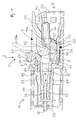
Figur 1 zeigt eine elektrische Steckverbindung mit einem Steckverbinder 1 und einem Gegensteckverbinder 10 (nur teilweise dargestellt) in seitlicher Schnittansicht. Die verwendeten Bezugszeichen haben folgende Bedeutung: - 1
- Steckverbinder
- 2
- Gehäuse des Steckverbinders
- 3
- Stromschiene
- 4
- Klemmfeder
- 5
- Betätigungselement
- 6
- Entriegelungselement
- 10
- Gegensteckverbinder
- 11
- Gehäuse des Gegensteckverbinders
- 12
- Steckanschlusskontakt des Gegensteckverbinders
- 13
- zweite Verriegelungseinrichtung des Gegensteckverbinders
- 20
- Leitereinstecköffnung
- 21
- Gehäusebereich
- 22
- Einführöffnung
- 23
- erste Verriegelungseinrichtung des Steckverbinders
- 24
- Anschlagfläche
- 30
- Leiteranschlussbereich
- 31
- Halteabschnitt
- 32
- Vertikalabschnitt
- 33
- Steckanschlusskontakt des Steckverbinders
- 40
- Anlageschenkel
- 41
- Endabschnitt
- 42
- mehrfach abgebogener Bereich
- 43
- Federbogen
- 44
- Klemmschenkel
- 44a
- nach oben hin ausgelenkter Klemmschenkel
- 45
- Klemmzunge
- 50
- Griffbereich des Betätigungselements (geschlossene Stellung)
- 50a
- Griffbereich des Betätigungselements (geöffnete Stellung)
- 52
- Federmitnehmer
- 60
- manueller Betätigungsbereich des Entriegelungselementes
- 61
- Betätigungsnase
- 62
- Lagerzapfen
- 63
- Anschlagelement
- B
- Betätigungsrichtung
- L
- Leitereinsteckrichtung
- S
- Steckrichtung
- Der Steckverbinder 1 weist ein Gehäuse 2 auf, z.B. ein Isolierstoffgehäuse. Das Gehäuse 2 weist eine Leitereinstecköffnung 20 auf. Durch die Leitereinstecköffnung 20 kann ein elektrischer Leiter in einer Leitereinsteckrichtung L eingesteckt werden und an einer nachfolgend noch beschriebenen Klemmstelle angeklemmt werden.
- Der Steckverbinder 1 weist außerdem einen Federkraftklemmanschluss mit einer Stromschiene 3 und einer Klemmfeder 4 auf, die als elektrischer Kontakteinsatz im Gehäuse 2 angeordnet sind. Die Klemmfeder 4 weist einen Anlageschenkel 40 auf, der mit einem endseitigen, im Wesentlichen vertikal zur Leitereinsteckrichtung L verlaufenden Endabschnitt 41 an einem ebenfalls im Wesentlichen vertikal zur Leitereinsteckrichtung L verlaufenden Halteabschnitt 31 der Stromschiene 3 befestigt ist. Auf diese Weise ist die Klemmfeder 4 an der Stromschiene 3 fixiert. Der Anlageschenkel 40 erstreckt sich über einen mehrfach abgebogenen Bereich 42 hin zu einem Federbogen 43, an den sich ein Klemmschenkel 44 der Klemmfeder 4 anschließt. Der Klemmschenkel 44 endet mit einer Klemmzunge 45, die zusammen mit einem Leiteranschlussbereich 30 der Stromschiene 3 eine Klemmstelle zum Anklemmen eines elektrischen Leiters bildet.
- Der Steckverbinder 1 weist außerdem ein Betätigungselement 5 in Form eines verschwenkbaren Betätigungshebels auf. Das Betätigungselement 5 weist einen Griffbereich 50 auf, an dem ein Benutzer manuell das Betätigungselement 5 betätigen kann. Das Betätigungselement 5 dient zum Öffnen der Klemmstelle, um das Einführen eines elektrischen Leiters zu erleichtern oder das Entfernen eines bereits angeklemmten elektrischen Leiters zu ermöglichen. Hierzu weist das Betätigungselement 5 einen Federmitnehmer 52 auf, der gegen einen Bereich des Klemmschenkels 44 drücken kann und auf diese Weise den Klemmschenkel 44 einschließlich der Klemmzunge 45 auslenken kann. Die
Figur 1 zeigt in durchgezogenen Linien die Klemmfeder bei geschlossener Klemmstelle. In diesem Fall ist auch das Betätigungselement in der geschlossenen Stellung, was ebenfalls in durchgezogenen Linien dargestellt ist. DieFigur 1 zeigt zusätzlich das Betätigungselement in der geöffneten Stellung, was mit strichpunktierten Linien dargestellt ist. In diesem Fall wird durch den Federmitnehmer 52 der Klemmschenkel 44 nach oben hin ausgelenkt, was mit dem Bezugszeichen 44a und die Darstellung des Klemmschenkels in gestrichelten Linien gekennzeichnet ist. Der Griffbereich 50 ist in diesem Fall mit dem Bezugszeichen 50a wiedergegeben. - Der Steckverbinder 1 weist außerdem in einem in Richtung zum Gegensteckverbinder 10 abragenden Gehäusebereich 21 einen Steckanschlusskontakt 33 auf, der bspw. durch zwei Gabelschenkel realisiert sein kann und dementsprechend einen Gabelkontakt bildet. Hierbei können die Gabelschenkel des Steckanschlusskontakts 33 einstückig mit der Stromschiene 3 ausgebildet sein, z.B. indem die Gabelschenkel 33 über einen Vertikalabschnitt 32 aus dem Stromschienenmaterial miteinander verbunden sind und diese wiederum mit dem Halteabschnitt 31 verbunden sind.
- Der Gegensteckverbinder 10 weist ein eigenes Gehäuse 11 auf, z.B. aus Isolierstoff. Der Gegensteckverbinder 10 weist einen Steckanschlusskontakt 12 auf, der als Gegenstück zum Steckanschlusskontakt 33 ausgebildet ist, z.B. als Messerkontakt oder als Stiftkontakt. Dieser Steckanschlusskontakt 12 kann durch eine Einführöffnung 22 im Gehäusebereich 21 in den Steckverbinder 1 eingeführt werden und wird zwischen den Gabelschenkeln des Steckanschlusskontakts 33 aufgenommen.
- Der Steckverbinder 1 kann dementsprechend in einer Steckrichtung S mit dem Gegensteckverbinder 10 zusammengesteckt werden.
- Um ein unerwünschtes Lösen des Steckverbinders 1 vom Gegensteckverbinder 10 zu verhindern, ist eine formschlüssige Verbindung über eine erste Verriegelungseinrichtung 23 des Steckverbinders und eine zweite Verriegelungseinrichtung 13 des Gegensteckverbinders vorgesehen. Wie die
Figur 1 zeigt, kann die erste Verriegelungseinrichtung 23 die zweite Verriegelungseinrichtung 13 formschlüssig hintergreifen bzw. dahinter einschnappen (im Sinne von Rastelementen). Zum Lösen dieser Fixierung, d.h. für einen Entriegelungsvorgang, kann der Bereich des Gehäuses 11 des Gegensteckverbinders 10, an dem die zweite Verriegelungseinrichtung 13 angeordnet ist, mittels eines Entriegelungselementes 6 mechanisch ausgelenkt werden, und zwar so weit, dass die formschlüssige Verbindung zwischen der ersten Verriegelungseinrichtung 23 und der zweiten Verriegelungseinrichtung 13 aufgehoben ist. - Hierfür kann die zweite Verriegelungseinrichtung 13 bspw. an einer flexiblen Lasche des Gehäuses 11 angeordnet sein.
- Das Entriegelungselement 6 ist am Steckverbinder 1 befestigt, z.B. an der Außenseite des Gehäuses 2. Das Entriegelungselement 6 ist als verschwenkbares, um eine Drehachse drehbares Entriegelungselement ausgebildet, das ähnlich wie eine Wippe beweglich ist. Das Entriegelungselement 6 weist einen manuellen Betätigungsbereich 60 auf, der zur manuellen Betätigung des Entriegelungselementes 6 dient. Um die Drehachse des Entriegelungselementes 6 zu realisieren, ist das Entriegelungselement 6 über eine Lagerachse, z.B. in Form von seitlich abragenden Lagerzapfen 62, am Gehäuse 2 drehbar gelagert. Am anderen Ende, d.h. auf der anderen Seite der durch die Lagerzapfen 62 gebildeten Verschwenkachse, endet das Entriegelungselement 6 mit einer abragenden Betätigungsnase 61, die einen Teil des Gehäuses 11 des Gegensteckverbinders 10 untergreift. Wird das Entriegelungselement 6 am manuellen Betätigungsbereich 60 in einer Betätigungsrichtung B betätigt, führt es eine Bewegung im Uhrzeigersinn aus, die begrenzt ist durch eine Anschlagfläche 24 des Gehäuses 2. Hierbei hebt die Betätigungsnase 61 den die zweite Verriegelungseinrichtung 13 aufweisenden Teil des Gehäuses 11 an, sodass die Fixierung aufgehoben ist.
- Erkennbar ist ferner, dass das Entriegelungselement 6 ein Anschlagelement 63 aufweist, das als Anschlag und Wegbegrenzung für das Betätigungselement 5 dient. Das Betätigungselement 5 kann in Richtung der geöffneten Stellung nur so weit bewegt werden, bis es am Anschlagelement 63 zur Anlage kommt.
- Wie ferner erkennbar ist, bewirkt das Betätigungselement 5, insbesondere dessen Griffbereich 50, in der geöffneten Stellung, dass das Entriegelungselement 6 nicht für einen Entriegelungsvorgang betätigt werden kann, weil das Anschlagelement 63 zur Anlage am Betätigungselement 5 kommt und somit eine weitere Bewegung des Entriegelungselementes 6 blockiert.
Claims (15)
- Elektrische Steckverbindung, die einen Steckverbinder (1) und einen dem Steckverbinder (1) als Gegenstück zugeordneten Gegensteckverbinder (10) aufweist, wobei der Steckverbinder (1) mit dem Gegensteckverbinder (10) zur Herstellung einer elektrischen Steckverbindung in einer Steckrichtung (S) zusammensteckbar ist, wobei der Steckverbinder (1) eine erste Verriegelungseinrichtung (23) aufweist und der Gegensteckverbinder (10) eine zweite Verriegelungseinrichtung (13) aufweist, wobei der Steckverbinder (1) an dem Gegensteckverbinder (10) durch eine formschlüssige Verbindung der ersten Verriegelungseinrichtung (23) mit der zweiten Verriegelungseinrichtung (13) fixierbar ist und bei einem Entriegelungsvorgang diese Fixierung durch manuelle Betätigung eines am Steckverbinder (1) oder am Gegensteckverbinder (10) beweglich befestigten Entriegelungselementes (6) lösbar ist, indem das Entriegelungselement (6) bei manueller Betätigung mechanisch auf die erste und/oder die zweite Verriegelungseinrichtung (23, 13) einwirkt, dadurch gekennzeichnet, dass das Entriegelungselement (6) um eine Verschwenkachse verschwenkbar an dem Steckverbinder (1) oder dem Gegensteckverbinder (10) befestigt ist, wobei das Entriegelungselement (6) auf einer Seite der Verschwenkachse einen manuellen Betätigungsbereich (60), der zur manuellen Betätigung des Entriegelungselementes (6) eingerichtet ist, und auf der anderen Seite der Verschwenkachse eine abragende Betätigungsnase (61) aufweist, durch die die erste und/oder die zweite Verriegelungseinrichtung (23, 13) bei dem Entriegelungsvorgang mechanisch auslenkbar ist.
- Steckverbindung nach dem vorhergehenden Anspruch, dadurch gekennzeichnet, dass das Entriegelungselement (6) in einer Betätigungsrichtung (B) betätigbar ist, die winklig zur Steckrichtung (S) der Steckverbindung angeordnet ist.
- Steckverbindung nach dem vorhergehenden Anspruch, dadurch gekennzeichnet, dass die Betätigungsrichtung (B) im Wesentlichen rechtwinklig zur Steckrichtung (S) der Steckverbindung angeordnet ist.
- Steckverbindung nach einem der vorhergehenden Ansprüche, dadurch gekennzeichnet, dass wenigstens ein Gehäusebauteil des Steckverbinders (1) oder des Gegensteckverbinders (10) bei dem Entriegelungsvorgang durch das Entriegelungselement (6) aufweitbar ist.
- Steckverbindung nach einem der vorhergehenden Ansprüche, dadurch gekennzeichnet, dass dasjenige Bauteil von Steckverbinder (1) und Gegensteckverbinder (10), das das Entriegelungselement (6) aufweist, wenigstens einen Federkraftklemmanschluss zum Anklemmen eines elektrischen Leiters an einer Klemmstelle mittels Federkraft aufweist, wobei der Federkraftklemmanschluss durch ein Betätigungselement (5) dieses Bauteils von einer geschlossenen Stellung in eine geöffnete Stellung bewegbar ist.
- Steckverbindung nach dem vorhergehenden Anspruch, dadurch gekennzeichnet, dass das Entriegelungselement (6), insbesondere der manuelle Betätigungsbereich (60) des Entriegelungselementes (6) oder ein Anschlagbereich (63) des Entriegelungselementes (6), einen mechanischen Anschlag für das Betätigungselement (5) in der geöffneten Stellung bildet.
- Steckverbindung nach Anspruch 5 oder 6, dadurch gekennzeichnet, dass das Entriegelungselement (6) durch das Betätigungselement (5) gegen manuelle Betätigung blockiert ist, wenn das Betätigungselement (5) in der geöffneten Stellung ist.
- Steckverbindung nach einem der vorhergehenden Ansprüche, dadurch gekennzeichnet, dass das Entriegelungselement (6) im Wesentlichen mittig im Bereich von Steckkontakten des Steckverbinders (1) und/oder des Gegensteckverbinders (10) angeordnet ist.
- Steckverbindung nach einem der vorhergehenden Ansprüche, dadurch gekennzeichnet, dass der Federkraftklemmanschluss eine Stromschiene (3) und eine Klemmfeder (4) aufweist, wobei die Klemmfeder (4) selbsttragend an der Stromschiene (3) befestigt ist.
- Steckverbindung nach einem der vorhergehenden Ansprüche, dadurch gekennzeichnet, dass die Stromschiene (3) und/oder die Klemmfeder (4) einstückig mit zumindest einem Teil eines Steckanschlusskontaktes (33, 12) des Steckverbinders (1) oder Gegensteckverbinders (10) ausgebildet ist.
- Steckverbindung nach einem der vorhergehenden Ansprüche, dadurch gekennzeichnet, dass die Leitereinsteckrichtung (L) des Federkraftklemmanschlusses im Wesentlichen parallel oder identisch zur Steckrichtung (S) ist.
- Steckverbindung nach einem der vorhergehenden Ansprüche, dadurch gekennzeichnet, dass die Klemmfeder (4) einen Klemmschenkel (44) zum Festklemmen eines elektrischen Leiters aufweist, wobei sich an den Klemmschenkel (44) ein Federbogen (43) und an den Federbogen (43) ein Anlageschenkel (40) anschließt, der an der Stromschiene (3) befestigt ist.
- Steckverbindung nach dem vorhergehenden Anspruch, dadurch gekennzeichnet, dass der Federbogen (43) von dem Anlageschenkel (40) aus entgegen der Leitereinsteckrichtung (L) fortweist.
- Steckverbindung nach Anspruch 12 oder 13, dadurch gekennzeichnet, dass der Anlageschenkel (40) mehrfach abgebogen mit wenigstens zwei in entgegengesetztem Biegesinn gebogenen Bereichen (42) ausgebildet ist.
- Steckverbindung nach einem der Ansprüche 12 bis 14, dadurch gekennzeichnet, dass sich der Anlageschenkel (40), insbesondere der mehrfach abgebogene Bereich (42) des Anlageschenkels (40), durch einen vom Betätigungselement (5) umgebenen Freiraum hindurcherstreckt.
Applications Claiming Priority (1)
| Application Number | Priority Date | Filing Date | Title |
|---|---|---|---|
| DE102018102011.2A DE102018102011B4 (de) | 2018-01-30 | 2018-01-30 | Elektrische Steckverbindung |
Publications (2)
| Publication Number | Publication Date |
|---|---|
| EP3518350A1 true EP3518350A1 (de) | 2019-07-31 |
| EP3518350B1 EP3518350B1 (de) | 2020-06-24 |
Family
ID=65228472
Family Applications (1)
| Application Number | Title | Priority Date | Filing Date |
|---|---|---|---|
| EP19153532.7A Active EP3518350B1 (de) | 2018-01-30 | 2019-01-24 | Elektrische steckverbindung |
Country Status (4)
| Country | Link |
|---|---|
| US (1) | US10608377B2 (de) |
| EP (1) | EP3518350B1 (de) |
| CN (1) | CN110098524B (de) |
| DE (1) | DE102018102011B4 (de) |
Families Citing this family (10)
| Publication number | Priority date | Publication date | Assignee | Title |
|---|---|---|---|---|
| DE202019105676U1 (de) * | 2019-08-29 | 2020-12-01 | Wago Verwaltungsgesellschaft Mbh | Elektrische Steckverbindung und Verriegelungselement |
| DE102021101505A1 (de) * | 2020-01-31 | 2021-08-05 | WAGO Verwaltungsgesellschaft mit beschränkter Haftung | Leiteranschlussklemme |
| DE102020106634B3 (de) * | 2020-03-11 | 2021-06-17 | WAGO Verwaltungsgesellschaft mit beschränkter Haftung | Elektrische Steckverbindung und Entriegelungselement |
| AU2021292753B2 (en) | 2020-06-18 | 2023-12-21 | Ideal Industries, Inc. | Conductor terminal |
| CN112397922A (zh) * | 2020-09-18 | 2021-02-23 | 昆山元太金精密工业有限公司 | 一种电子连接器及其制作方法 |
| DE102021110425A1 (de) * | 2021-04-23 | 2022-10-27 | WAGO Verwaltungsgesellschaft mit beschränkter Haftung | Leiteranschlussklemme und Steckdoseneinsatz |
| LU500295B1 (de) * | 2021-06-17 | 2022-12-19 | Phoenix Contact Gmbh & Co | Steckverbinder mit Verriegelungselement |
| DE102023104274B3 (de) * | 2023-02-21 | 2024-05-23 | Lisa Dräxlmaier GmbH | Steckverbindungssystem, steckverbindungselement sowie steckverbindung |
| CN117154461B (zh) * | 2023-09-21 | 2026-03-24 | 町洋机电(中国)有限公司 | 用于连接电导体的连接器 |
| WO2026020033A1 (en) * | 2024-07-17 | 2026-01-22 | Ideal Industries, Inc. | Lever connector manual lock |
Citations (6)
| Publication number | Priority date | Publication date | Assignee | Title |
|---|---|---|---|---|
| FR2489049A1 (fr) * | 1980-08-19 | 1982-02-26 | Bosch Gmbh Robert | Connexion enfichable a plusieurs poles |
| DE202010003117U1 (de) * | 2010-03-03 | 2010-05-27 | Wago Verwaltungsgesellschaft Mbh | Steckverbindervorrichtung mit einer Entriegelungsvorrichtung |
| EP2445056A1 (de) * | 2010-10-19 | 2012-04-25 | Wago Verwaltungsgesellschaft mbH | Elektrische Verbindungsklemme |
| DE102012104857A1 (de) * | 2012-06-05 | 2013-12-05 | Wago Verwaltungsgesellschaft Mbh | Elektrische Steckverbindung |
| WO2017102829A1 (de) * | 2015-12-17 | 2017-06-22 | Wago Verwaltungsgesellschaft Mbh | Leiteranschlussklemme |
| US20170214154A1 (en) * | 2013-10-21 | 2017-07-27 | Wago Verwaltungsgesellschaft Mbh | Spring-force terminal connection and plug connector |
Family Cites Families (20)
| Publication number | Priority date | Publication date | Assignee | Title |
|---|---|---|---|---|
| US3713076A (en) * | 1971-09-30 | 1973-01-23 | Electronic Eng Co | Locking electrical cable connection apparatus |
| FR2421486A1 (fr) * | 1978-03-31 | 1979-10-26 | Socapex | Dispositif de deverrouillage et d'extraction pour connecteur electrique, et connecteur electrique muni d'un tel dispositif |
| GB2082401B (en) | 1980-08-06 | 1984-10-17 | Flair Electronic Systems Ltd | Locking and extracting mechanism for electrical connectors |
| US4531795A (en) * | 1983-03-01 | 1985-07-30 | Aries Electronics, Inc. | Ejector socket for DIP jumpers |
| US4658107A (en) * | 1985-12-24 | 1987-04-14 | Emerson Electric Co. | Plug assembly and interconnection system |
| US4708413A (en) * | 1986-03-21 | 1987-11-24 | General Motors Corporation | Electrical connector with position assurance and assist |
| US4714433A (en) * | 1987-01-21 | 1987-12-22 | General Motors Corporation | Electrical connector with position assurance and double lock |
| JPH082939Y2 (ja) * | 1988-05-30 | 1996-01-29 | 矢崎総業株式会社 | コネクタの二重ロック装置 |
| US4946395A (en) * | 1989-07-17 | 1990-08-07 | General Motors Corporation | Electrical connector with connector position assurance device |
| JP2570376Y2 (ja) * | 1992-08-04 | 1998-05-06 | 矢崎総業株式会社 | コネクタのロック装置 |
| JP2001250636A (ja) | 2000-03-03 | 2001-09-14 | Yazaki Corp | コネクタのロック構造 |
| JP3609379B2 (ja) * | 2002-01-31 | 2005-01-12 | 日本圧着端子製造株式会社 | ロック機構付き電気コネクタ |
| JP2003243093A (ja) * | 2002-02-21 | 2003-08-29 | Yazaki Corp | Usbコネクタ |
| JP3963849B2 (ja) * | 2003-02-26 | 2007-08-22 | 矢崎総業株式会社 | コネクタのロック構造 |
| JP5563241B2 (ja) * | 2009-05-15 | 2014-07-30 | スリーエム イノベイティブ プロパティズ カンパニー | 電気コネクタ |
| DE102011102715B4 (de) * | 2011-05-20 | 2016-08-18 | Wago Verwaltungsgesellschaft Mbh | Steckverbinderset und Platte hierzu |
| JP6633824B2 (ja) * | 2014-03-31 | 2020-01-22 | 矢崎総業株式会社 | コネクタ |
| CN204156216U (zh) * | 2014-09-18 | 2015-02-11 | 番禺得意精密电子工业有限公司 | 电连接组件 |
| US9595789B1 (en) * | 2016-02-10 | 2017-03-14 | I.D. Systems, Inc. | Connector locking mechanism having a sliding connection retention component |
| CN206163833U (zh) * | 2016-10-20 | 2017-05-10 | 唐兴然 | 公插接件和母插接件和高压连接器 |
-
2018
- 2018-01-30 DE DE102018102011.2A patent/DE102018102011B4/de active Active
- 2018-12-29 CN CN201811640063.8A patent/CN110098524B/zh active Active
-
2019
- 2019-01-24 EP EP19153532.7A patent/EP3518350B1/de active Active
- 2019-01-30 US US16/262,328 patent/US10608377B2/en not_active Expired - Fee Related
Patent Citations (6)
| Publication number | Priority date | Publication date | Assignee | Title |
|---|---|---|---|---|
| FR2489049A1 (fr) * | 1980-08-19 | 1982-02-26 | Bosch Gmbh Robert | Connexion enfichable a plusieurs poles |
| DE202010003117U1 (de) * | 2010-03-03 | 2010-05-27 | Wago Verwaltungsgesellschaft Mbh | Steckverbindervorrichtung mit einer Entriegelungsvorrichtung |
| EP2445056A1 (de) * | 2010-10-19 | 2012-04-25 | Wago Verwaltungsgesellschaft mbH | Elektrische Verbindungsklemme |
| DE102012104857A1 (de) * | 2012-06-05 | 2013-12-05 | Wago Verwaltungsgesellschaft Mbh | Elektrische Steckverbindung |
| US20170214154A1 (en) * | 2013-10-21 | 2017-07-27 | Wago Verwaltungsgesellschaft Mbh | Spring-force terminal connection and plug connector |
| WO2017102829A1 (de) * | 2015-12-17 | 2017-06-22 | Wago Verwaltungsgesellschaft Mbh | Leiteranschlussklemme |
Also Published As
| Publication number | Publication date |
|---|---|
| US20190237904A1 (en) | 2019-08-01 |
| DE102018102011A1 (de) | 2019-08-01 |
| CN110098524A (zh) | 2019-08-06 |
| CN110098524B (zh) | 2022-05-27 |
| US10608377B2 (en) | 2020-03-31 |
| EP3518350B1 (de) | 2020-06-24 |
| DE102018102011B4 (de) | 2020-07-02 |
Similar Documents
| Publication | Publication Date | Title |
|---|---|---|
| EP3518350B1 (de) | Elektrische steckverbindung | |
| EP2324533B1 (de) | Elektrische anschlussklemme | |
| EP2162952B1 (de) | Elektrische anschluss- oder verbindungsklemme | |
| EP3235061B1 (de) | Elektrische anschlussklemme | |
| DE102016118331B4 (de) | Leiteranschlussklemme zum Anschluss elektrischer Leiter | |
| WO2016116476A1 (de) | Elektrische anschlussklemme mit zweiteiligem betätigungselement | |
| EP3586404B1 (de) | Federkraftanschluss und rundsteckverbinder mit einer vielzahl von federkraftanschlüssen | |
| WO2017102829A1 (de) | Leiteranschlussklemme | |
| DE102017107943B3 (de) | Verriegelungsmechanismus zur lösbaren Verriegelung eines ersten Bauteils an einem zweiten Bauteil sowie damit gebildete Anordnung | |
| WO2019192911A1 (de) | Elektrischer steckverbinder, modulares system und verfahren zur bereitstellung eines steckverbinders | |
| DE102016108826A1 (de) | Anschlussklemme | |
| DE102006054647B4 (de) | Elektrische Steckverbinderkupplung | |
| EP3493333A1 (de) | Elektrische steckverbindung zur datenübertragung | |
| DE10005858A1 (de) | Steckverbinder | |
| DE202007009193U1 (de) | Elektrischer Steckverbinder mit Schenkelfederklemme | |
| EP4189782B1 (de) | Leiteranschlussklemme | |
| EP0768733A2 (de) | Elektrischer Stecker mit einem Betätigungsschieber | |
| DE102022113144A1 (de) | Steckverbinder mit einer rasteinrichtung zur verriegelung einer steckverbindung mit einem gegensteckverbinder, gegensteckverbinder sowie anordnung mit einem steckverbinder und einem gegensteckverbinder | |
| DE102020106634B3 (de) | Elektrische Steckverbindung und Entriegelungselement | |
| EP3685473A1 (de) | Anschlusseinrichtung zum anschliessen einer elektrischen leitung | |
| DE102018010384B4 (de) | Elektrische Steckverbindung | |
| EP3945639A1 (de) | Leiteranschlussklemme | |
| DE102016105428B4 (de) | Anschlussklemme | |
| DE102019135507A1 (de) | Elektrische Steckverbindung und Verriegelungselement | |
| DE202017106708U1 (de) | Anschlussklemme |
Legal Events
| Date | Code | Title | Description |
|---|---|---|---|
| PUAI | Public reference made under article 153(3) epc to a published international application that has entered the european phase |
Free format text: ORIGINAL CODE: 0009012 |
|
| STAA | Information on the status of an ep patent application or granted ep patent |
Free format text: STATUS: REQUEST FOR EXAMINATION WAS MADE |
|
| 17P | Request for examination filed |
Effective date: 20190605 |
|
| AK | Designated contracting states |
Kind code of ref document: A1 Designated state(s): AL AT BE BG CH CY CZ DE DK EE ES FI FR GB GR HR HU IE IS IT LI LT LU LV MC MK MT NL NO PL PT RO RS SE SI SK SM TR |
|
| AX | Request for extension of the european patent |
Extension state: BA ME |
|
| RIC1 | Information provided on ipc code assigned before grant |
Ipc: H01R 4/48 20060101ALI20190918BHEP Ipc: H01R 11/05 20060101ALN20190918BHEP Ipc: H01R 13/11 20060101ALN20190918BHEP Ipc: H01R 13/627 20060101AFI20190918BHEP Ipc: H01R 13/635 20060101ALI20190918BHEP |
|
| GRAP | Despatch of communication of intention to grant a patent |
Free format text: ORIGINAL CODE: EPIDOSNIGR1 |
|
| STAA | Information on the status of an ep patent application or granted ep patent |
Free format text: STATUS: GRANT OF PATENT IS INTENDED |
|
| INTG | Intention to grant announced |
Effective date: 20191031 |
|
| GRAS | Grant fee paid |
Free format text: ORIGINAL CODE: EPIDOSNIGR3 |
|
| GRAA | (expected) grant |
Free format text: ORIGINAL CODE: 0009210 |
|
| STAA | Information on the status of an ep patent application or granted ep patent |
Free format text: STATUS: THE PATENT HAS BEEN GRANTED |
|
| AK | Designated contracting states |
Kind code of ref document: B1 Designated state(s): AL AT BE BG CH CY CZ DE DK EE ES FI FR GB GR HR HU IE IS IT LI LT LU LV MC MK MT NL NO PL PT RO RS SE SI SK SM TR |
|
| REG | Reference to a national code |
Ref country code: GB Ref legal event code: FG4D Free format text: NOT ENGLISH |
|
| REG | Reference to a national code |
Ref country code: CH Ref legal event code: EP |
|
| REG | Reference to a national code |
Ref country code: DE Ref legal event code: R096 Ref document number: 502019000069 Country of ref document: DE |
|
| REG | Reference to a national code |
Ref country code: AT Ref legal event code: REF Ref document number: 1284815 Country of ref document: AT Kind code of ref document: T Effective date: 20200715 |
|
| REG | Reference to a national code |
Ref country code: IE Ref legal event code: FG4D Free format text: LANGUAGE OF EP DOCUMENT: GERMAN |
|
| PG25 | Lapsed in a contracting state [announced via postgrant information from national office to epo] |
Ref country code: FI Free format text: LAPSE BECAUSE OF FAILURE TO SUBMIT A TRANSLATION OF THE DESCRIPTION OR TO PAY THE FEE WITHIN THE PRESCRIBED TIME-LIMIT Effective date: 20200624 Ref country code: SE Free format text: LAPSE BECAUSE OF FAILURE TO SUBMIT A TRANSLATION OF THE DESCRIPTION OR TO PAY THE FEE WITHIN THE PRESCRIBED TIME-LIMIT Effective date: 20200624 Ref country code: LT Free format text: LAPSE BECAUSE OF FAILURE TO SUBMIT A TRANSLATION OF THE DESCRIPTION OR TO PAY THE FEE WITHIN THE PRESCRIBED TIME-LIMIT Effective date: 20200624 Ref country code: GR Free format text: LAPSE BECAUSE OF FAILURE TO SUBMIT A TRANSLATION OF THE DESCRIPTION OR TO PAY THE FEE WITHIN THE PRESCRIBED TIME-LIMIT Effective date: 20200925 Ref country code: NO Free format text: LAPSE BECAUSE OF FAILURE TO SUBMIT A TRANSLATION OF THE DESCRIPTION OR TO PAY THE FEE WITHIN THE PRESCRIBED TIME-LIMIT Effective date: 20200924 |
|
| REG | Reference to a national code |
Ref country code: LT Ref legal event code: MG4D |
|
| PG25 | Lapsed in a contracting state [announced via postgrant information from national office to epo] |
Ref country code: BG Free format text: LAPSE BECAUSE OF FAILURE TO SUBMIT A TRANSLATION OF THE DESCRIPTION OR TO PAY THE FEE WITHIN THE PRESCRIBED TIME-LIMIT Effective date: 20200924 Ref country code: RS Free format text: LAPSE BECAUSE OF FAILURE TO SUBMIT A TRANSLATION OF THE DESCRIPTION OR TO PAY THE FEE WITHIN THE PRESCRIBED TIME-LIMIT Effective date: 20200624 Ref country code: LV Free format text: LAPSE BECAUSE OF FAILURE TO SUBMIT A TRANSLATION OF THE DESCRIPTION OR TO PAY THE FEE WITHIN THE PRESCRIBED TIME-LIMIT Effective date: 20200624 Ref country code: HR Free format text: LAPSE BECAUSE OF FAILURE TO SUBMIT A TRANSLATION OF THE DESCRIPTION OR TO PAY THE FEE WITHIN THE PRESCRIBED TIME-LIMIT Effective date: 20200624 |
|
| REG | Reference to a national code |
Ref country code: NL Ref legal event code: MP Effective date: 20200624 |
|
| PG25 | Lapsed in a contracting state [announced via postgrant information from national office to epo] |
Ref country code: NL Free format text: LAPSE BECAUSE OF FAILURE TO SUBMIT A TRANSLATION OF THE DESCRIPTION OR TO PAY THE FEE WITHIN THE PRESCRIBED TIME-LIMIT Effective date: 20200624 Ref country code: AL Free format text: LAPSE BECAUSE OF FAILURE TO SUBMIT A TRANSLATION OF THE DESCRIPTION OR TO PAY THE FEE WITHIN THE PRESCRIBED TIME-LIMIT Effective date: 20200624 |
|
| PG25 | Lapsed in a contracting state [announced via postgrant information from national office to epo] |
Ref country code: ES Free format text: LAPSE BECAUSE OF FAILURE TO SUBMIT A TRANSLATION OF THE DESCRIPTION OR TO PAY THE FEE WITHIN THE PRESCRIBED TIME-LIMIT Effective date: 20200624 Ref country code: SM Free format text: LAPSE BECAUSE OF FAILURE TO SUBMIT A TRANSLATION OF THE DESCRIPTION OR TO PAY THE FEE WITHIN THE PRESCRIBED TIME-LIMIT Effective date: 20200624 Ref country code: EE Free format text: LAPSE BECAUSE OF FAILURE TO SUBMIT A TRANSLATION OF THE DESCRIPTION OR TO PAY THE FEE WITHIN THE PRESCRIBED TIME-LIMIT Effective date: 20200624 Ref country code: CZ Free format text: LAPSE BECAUSE OF FAILURE TO SUBMIT A TRANSLATION OF THE DESCRIPTION OR TO PAY THE FEE WITHIN THE PRESCRIBED TIME-LIMIT Effective date: 20200624 Ref country code: IT Free format text: LAPSE BECAUSE OF FAILURE TO SUBMIT A TRANSLATION OF THE DESCRIPTION OR TO PAY THE FEE WITHIN THE PRESCRIBED TIME-LIMIT Effective date: 20200624 Ref country code: RO Free format text: LAPSE BECAUSE OF FAILURE TO SUBMIT A TRANSLATION OF THE DESCRIPTION OR TO PAY THE FEE WITHIN THE PRESCRIBED TIME-LIMIT Effective date: 20200624 Ref country code: PT Free format text: LAPSE BECAUSE OF FAILURE TO SUBMIT A TRANSLATION OF THE DESCRIPTION OR TO PAY THE FEE WITHIN THE PRESCRIBED TIME-LIMIT Effective date: 20201026 |
|
| PG25 | Lapsed in a contracting state [announced via postgrant information from national office to epo] |
Ref country code: PL Free format text: LAPSE BECAUSE OF FAILURE TO SUBMIT A TRANSLATION OF THE DESCRIPTION OR TO PAY THE FEE WITHIN THE PRESCRIBED TIME-LIMIT Effective date: 20200624 Ref country code: SK Free format text: LAPSE BECAUSE OF FAILURE TO SUBMIT A TRANSLATION OF THE DESCRIPTION OR TO PAY THE FEE WITHIN THE PRESCRIBED TIME-LIMIT Effective date: 20200624 Ref country code: IS Free format text: LAPSE BECAUSE OF FAILURE TO SUBMIT A TRANSLATION OF THE DESCRIPTION OR TO PAY THE FEE WITHIN THE PRESCRIBED TIME-LIMIT Effective date: 20201024 |
|
| REG | Reference to a national code |
Ref country code: DE Ref legal event code: R097 Ref document number: 502019000069 Country of ref document: DE |
|
| PG25 | Lapsed in a contracting state [announced via postgrant information from national office to epo] |
Ref country code: DK Free format text: LAPSE BECAUSE OF FAILURE TO SUBMIT A TRANSLATION OF THE DESCRIPTION OR TO PAY THE FEE WITHIN THE PRESCRIBED TIME-LIMIT Effective date: 20200624 |
|
| PLBE | No opposition filed within time limit |
Free format text: ORIGINAL CODE: 0009261 |
|
| STAA | Information on the status of an ep patent application or granted ep patent |
Free format text: STATUS: NO OPPOSITION FILED WITHIN TIME LIMIT |
|
| 26N | No opposition filed |
Effective date: 20210325 |
|
| PG25 | Lapsed in a contracting state [announced via postgrant information from national office to epo] |
Ref country code: SI Free format text: LAPSE BECAUSE OF FAILURE TO SUBMIT A TRANSLATION OF THE DESCRIPTION OR TO PAY THE FEE WITHIN THE PRESCRIBED TIME-LIMIT Effective date: 20200624 Ref country code: MC Free format text: LAPSE BECAUSE OF FAILURE TO SUBMIT A TRANSLATION OF THE DESCRIPTION OR TO PAY THE FEE WITHIN THE PRESCRIBED TIME-LIMIT Effective date: 20200624 |
|
| PG25 | Lapsed in a contracting state [announced via postgrant information from national office to epo] |
Ref country code: LU Free format text: LAPSE BECAUSE OF NON-PAYMENT OF DUE FEES Effective date: 20210124 |
|
| REG | Reference to a national code |
Ref country code: BE Ref legal event code: MM Effective date: 20210131 |
|
| PG25 | Lapsed in a contracting state [announced via postgrant information from national office to epo] |
Ref country code: FR Free format text: LAPSE BECAUSE OF NON-PAYMENT OF DUE FEES Effective date: 20210131 |
|
| PG25 | Lapsed in a contracting state [announced via postgrant information from national office to epo] |
Ref country code: IE Free format text: LAPSE BECAUSE OF NON-PAYMENT OF DUE FEES Effective date: 20210124 |
|
| PG25 | Lapsed in a contracting state [announced via postgrant information from national office to epo] |
Ref country code: BE Free format text: LAPSE BECAUSE OF NON-PAYMENT OF DUE FEES Effective date: 20210131 |
|
| REG | Reference to a national code |
Ref country code: CH Ref legal event code: PL |
|
| PG25 | Lapsed in a contracting state [announced via postgrant information from national office to epo] |
Ref country code: LI Free format text: LAPSE BECAUSE OF NON-PAYMENT OF DUE FEES Effective date: 20220131 Ref country code: CH Free format text: LAPSE BECAUSE OF NON-PAYMENT OF DUE FEES Effective date: 20220131 |
|
| REG | Reference to a national code |
Ref country code: DE Ref legal event code: R082 Ref document number: 502019000069 Country of ref document: DE Representative=s name: MEISSNER BOLTE PATENTANWAELTE RECHTSANWAELTE P, DE |
|
| P01 | Opt-out of the competence of the unified patent court (upc) registered |
Effective date: 20230516 |
|
| PG25 | Lapsed in a contracting state [announced via postgrant information from national office to epo] |
Ref country code: CY Free format text: LAPSE BECAUSE OF FAILURE TO SUBMIT A TRANSLATION OF THE DESCRIPTION OR TO PAY THE FEE WITHIN THE PRESCRIBED TIME-LIMIT Effective date: 20200624 |
|
| PG25 | Lapsed in a contracting state [announced via postgrant information from national office to epo] |
Ref country code: HU Free format text: LAPSE BECAUSE OF FAILURE TO SUBMIT A TRANSLATION OF THE DESCRIPTION OR TO PAY THE FEE WITHIN THE PRESCRIBED TIME-LIMIT; INVALID AB INITIO Effective date: 20190124 |
|
| GBPC | Gb: european patent ceased through non-payment of renewal fee |
Effective date: 20230124 |
|
| PG25 | Lapsed in a contracting state [announced via postgrant information from national office to epo] |
Ref country code: GB Free format text: LAPSE BECAUSE OF NON-PAYMENT OF DUE FEES Effective date: 20230124 |
|
| PG25 | Lapsed in a contracting state [announced via postgrant information from national office to epo] |
Ref country code: MK Free format text: LAPSE BECAUSE OF FAILURE TO SUBMIT A TRANSLATION OF THE DESCRIPTION OR TO PAY THE FEE WITHIN THE PRESCRIBED TIME-LIMIT Effective date: 20200624 |
|
| PG25 | Lapsed in a contracting state [announced via postgrant information from national office to epo] |
Ref country code: MT Free format text: LAPSE BECAUSE OF FAILURE TO SUBMIT A TRANSLATION OF THE DESCRIPTION OR TO PAY THE FEE WITHIN THE PRESCRIBED TIME-LIMIT Effective date: 20200624 |
|
| REG | Reference to a national code |
Ref country code: AT Ref legal event code: MM01 Ref document number: 1284815 Country of ref document: AT Kind code of ref document: T Effective date: 20240124 |
|
| PG25 | Lapsed in a contracting state [announced via postgrant information from national office to epo] |
Ref country code: AT Free format text: LAPSE BECAUSE OF NON-PAYMENT OF DUE FEES Effective date: 20240124 |
|
| PG25 | Lapsed in a contracting state [announced via postgrant information from national office to epo] |
Ref country code: TR Free format text: LAPSE BECAUSE OF FAILURE TO SUBMIT A TRANSLATION OF THE DESCRIPTION OR TO PAY THE FEE WITHIN THE PRESCRIBED TIME-LIMIT Effective date: 20200624 |
|
| PGFP | Annual fee paid to national office [announced via postgrant information from national office to epo] |
Ref country code: DE Payment date: 20260127 Year of fee payment: 8 |
|
| PGFP | Annual fee paid to national office [announced via postgrant information from national office to epo] |
Ref country code: AT Payment date: 20260410 Year of fee payment: 5 |