EP3518049B1 - Image heating apparatus and image forming apparatus - Google Patents
Image heating apparatus and image forming apparatus Download PDFInfo
- Publication number
- EP3518049B1 EP3518049B1 EP19153428.8A EP19153428A EP3518049B1 EP 3518049 B1 EP3518049 B1 EP 3518049B1 EP 19153428 A EP19153428 A EP 19153428A EP 3518049 B1 EP3518049 B1 EP 3518049B1
- Authority
- EP
- European Patent Office
- Prior art keywords
- heat generating
- temperature
- target temperature
- power
- power supply
- Prior art date
- Legal status (The legal status is an assumption and is not a legal conclusion. Google has not performed a legal analysis and makes no representation as to the accuracy of the status listed.)
- Active
Links
Images


Classifications
-
- G—PHYSICS
- G03—PHOTOGRAPHY; CINEMATOGRAPHY; ANALOGOUS TECHNIQUES USING WAVES OTHER THAN OPTICAL WAVES; ELECTROGRAPHY; HOLOGRAPHY
- G03G—ELECTROGRAPHY; ELECTROPHOTOGRAPHY; MAGNETOGRAPHY
- G03G15/00—Apparatus for electrographic processes using a charge pattern
- G03G15/20—Apparatus for electrographic processes using a charge pattern for fixing, e.g. by using heat
- G03G15/2003—Apparatus for electrographic processes using a charge pattern for fixing, e.g. by using heat using heat
- G03G15/2014—Apparatus for electrographic processes using a charge pattern for fixing, e.g. by using heat using heat using contact heat
- G03G15/2039—Apparatus for electrographic processes using a charge pattern for fixing, e.g. by using heat using heat using contact heat with means for controlling the fixing temperature
- G03G15/2042—Apparatus for electrographic processes using a charge pattern for fixing, e.g. by using heat using heat using contact heat with means for controlling the fixing temperature specially for the axial heat partition
-
- G—PHYSICS
- G03—PHOTOGRAPHY; CINEMATOGRAPHY; ANALOGOUS TECHNIQUES USING WAVES OTHER THAN OPTICAL WAVES; ELECTROGRAPHY; HOLOGRAPHY
- G03G—ELECTROGRAPHY; ELECTROPHOTOGRAPHY; MAGNETOGRAPHY
- G03G15/00—Apparatus for electrographic processes using a charge pattern
- G03G15/20—Apparatus for electrographic processes using a charge pattern for fixing, e.g. by using heat
- G03G15/2003—Apparatus for electrographic processes using a charge pattern for fixing, e.g. by using heat using heat
- G03G15/2014—Apparatus for electrographic processes using a charge pattern for fixing, e.g. by using heat using heat using contact heat
- G03G15/2039—Apparatus for electrographic processes using a charge pattern for fixing, e.g. by using heat using heat using contact heat with means for controlling the fixing temperature
- G03G15/205—Apparatus for electrographic processes using a charge pattern for fixing, e.g. by using heat using heat using contact heat with means for controlling the fixing temperature specially for the mode of operation, e.g. standby, warming-up, error
-
- G—PHYSICS
- G03—PHOTOGRAPHY; CINEMATOGRAPHY; ANALOGOUS TECHNIQUES USING WAVES OTHER THAN OPTICAL WAVES; ELECTROGRAPHY; HOLOGRAPHY
- G03G—ELECTROGRAPHY; ELECTROPHOTOGRAPHY; MAGNETOGRAPHY
- G03G15/00—Apparatus for electrographic processes using a charge pattern
- G03G15/20—Apparatus for electrographic processes using a charge pattern for fixing, e.g. by using heat
- G03G15/2003—Apparatus for electrographic processes using a charge pattern for fixing, e.g. by using heat using heat
- G03G15/2014—Apparatus for electrographic processes using a charge pattern for fixing, e.g. by using heat using heat using contact heat
- G03G15/2053—Structural details of heat elements, e.g. structure of roller or belt, eddy current, induction heating
-
- G—PHYSICS
- G03—PHOTOGRAPHY; CINEMATOGRAPHY; ANALOGOUS TECHNIQUES USING WAVES OTHER THAN OPTICAL WAVES; ELECTROGRAPHY; HOLOGRAPHY
- G03G—ELECTROGRAPHY; ELECTROPHOTOGRAPHY; MAGNETOGRAPHY
- G03G15/00—Apparatus for electrographic processes using a charge pattern
- G03G15/50—Machine control of apparatus for electrographic processes using a charge pattern, e.g. regulating differents parts of the machine, multimode copiers, microprocessor control
- G03G15/5004—Power supply control, e.g. power-saving mode, automatic power turn-off
-
- G—PHYSICS
- G03—PHOTOGRAPHY; CINEMATOGRAPHY; ANALOGOUS TECHNIQUES USING WAVES OTHER THAN OPTICAL WAVES; ELECTROGRAPHY; HOLOGRAPHY
- G03G—ELECTROGRAPHY; ELECTROPHOTOGRAPHY; MAGNETOGRAPHY
- G03G15/00—Apparatus for electrographic processes using a charge pattern
- G03G15/20—Apparatus for electrographic processes using a charge pattern for fixing, e.g. by using heat
- G03G15/2003—Apparatus for electrographic processes using a charge pattern for fixing, e.g. by using heat using heat
- G03G15/2014—Apparatus for electrographic processes using a charge pattern for fixing, e.g. by using heat using heat using contact heat
- G03G15/2064—Apparatus for electrographic processes using a charge pattern for fixing, e.g. by using heat using heat using contact heat combined with pressure
-
- G—PHYSICS
- G03—PHOTOGRAPHY; CINEMATOGRAPHY; ANALOGOUS TECHNIQUES USING WAVES OTHER THAN OPTICAL WAVES; ELECTROGRAPHY; HOLOGRAPHY
- G03G—ELECTROGRAPHY; ELECTROPHOTOGRAPHY; MAGNETOGRAPHY
- G03G2215/00—Apparatus for electrophotographic processes
- G03G2215/00978—Details relating to power supplies
Definitions
- the present invention relates to an image heating apparatus such as a fixing unit for use in an electro-photographic or electrostatic recording type image forming apparatus such as a copier and a printer and a gloss applying apparatus for use in such an image forming apparatus which improves the gloss value of a toner image by reheating the toner image fixed on a recording material.
- the invention also relates to an image forming apparatus including the image heating apparatus.
- a method for heating image parts formed on a recording material independently from one another has been suggested in order to meet the demand for power saving in an image heating apparatus for use in an image forming apparatus such as a copier and a printer (Japanese Patent Application Publication No. JP H06 - 95 540 A ).
- the heat generation range of a heater (a heating region) is divided into a plurality of heat generating blocks with respect to the lengthwise direction of the heater (in the direction orthogonal to the conveyance direction of the recording material), and the heat generating blocks are independently controlled for heat generation depending on the presence/absence of an image on a recording material. More specifically, power supplied to a heat generating block is reduced in a part with no image on the recording material (a non-image part), so that power saving can be achieved.
- Document WO 2017/043 030 A1 discloses an image heating device and a corresponding heater.
- the image heating device has a plurality of heating blocks which are controllable independently in a longitudinal direction of a heater.
- a heater has a first temperature sensor corresponding to a first heating block, a second temperature sensor corresponding to a second heating block, a first electric conductor electrically coupled to the first temperature sensor, a second electric conductor electrically coupled to the second temperature sensor, and a common electric conductor electrically coupled to the first and second temperature sensors.
- the start-up time is short in some heat generating blocks and long in other heat generating blocks depending on the heat generating quantity of the heat generating blocks.
- the recording material is conveyed in synchronization with the start-up of a heat generating block with long start-up time, so that the blocks with shorter start-up time have to stand by at a higher temperature than the temperature of a heat generating block with longer start-up time while the recording material is conveyed thereto.
- the heat storage state varies immediately after the start-up, and an image defect such as gloss value unevenness and hot offset is observed in some cases.
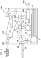
- FIG. 1 is a schematic sectional view of an image forming apparatus according to an embodiment of the present invention.
- the present invention may be applied to an image forming apparatus such as a copier and a printer according to an electro-photographic or electro-static recording method, and an example of application to a laser printer will be described here.
- An image forming apparatus 100 includes a video controller 120 and a control portion 113.
- the video controller 120 functions as an acquiring portion which acquires information on an image formed on a recording material and receives and processes image information and a printing instruction transmitted from an external device such as a personal computer.
- the control portion 113 is connected with the video controller 120 and controls various components of the image forming apparatus 100 in response to an instruction from the video controller 120.
- the control portion 113 is configured to control an estimating portion which estimates various kinds of start-up performance or an acquiring portion which acquires various kinds of start-up performance in temperature control of a heater which will be described and the control portion is a main component in the control.
- Image forming is carried out by the following operation when the video controller 120 receives a printing instruction from an external device.
- a scanner unit 21 When a printing signal is generated, a scanner unit 21 emits a laser beam modulated according to image information, and a photosensitive drum 19 charged to a prescribed polarity has its surface scanned by a charging roller 16. In this manner, an electrostatic latent image is formed on the photosensitive drum 19. As toner is supplied from a developing roller 17 to the electrostatic latent image, the electrostatic latent image on the photosensitive drum 19 is developed as a toner image. Meanwhile, sheets of recording material (recording sheets) P stacked in a sheet-feeding cassette 11 are fed on a one-sheet-basis by a pickup roller 12 and conveyed toward a pair of resist rollers 14 by a pair of conveyance rollers 13.
- the recording material P is then conveyed to a transfer position from the pair of resist rollers 14 in the timing in which the toner image on the photosensitive drum 19 reaches the transfer position formed by the photosensitive drum 19 and the transfer roller 20.
- the toner image on the photosensitive drum 19 is transferred onto the recording material P as the recording material P passes the transfer position.
- the recording material P is heated by a fixing apparatus (image heating apparatus) 200 as a fixing portion (image heating portion), so that the toner image is thermally fixed on the recording material P.
- the recording material P carrying the fixed toner image thereon is discharged onto a tray at the upper part of the image forming apparatus 100 by a pair of conveyance rollers 26 and 27.
- the reference numeral 18 represents a drum cleaner for cleaning the photosensitive drum 19
- the reference numeral 28 represents a sheet-feeding tray (a manual tray) having a pair of recording member restricting plates which can have its size adjusted according to the size of the recording material P.
- the sheet-feeding tray 28 is provided to address the recording material P in any of other sizes.
- the reference numeral 29 represents the pickup roller which feeds the recording material P from the sheet-feeding tray 28, and the reference numeral 30 represents a motor which drives the fixing apparatus 200, etc.
- a control circuit 400 functioning as heater driving means (a power supply control portion) connected to a commercially available AC power supply 401 supplies the fixing apparatus 200 with power.
- the photosensitive drum 19, the charging roller 16, the scanner unit 21, the developing roller 17, and the transfer roller 20 constitute the image forming portion which forms an unfixed image on the recording material P.
- the developing unit which includes the photosensitive drum 19, the charging roller 16, and the developing roller 17 and a cleaning unit which includes the drum cleaner 18 are configured as a process cartridge 15 to be detachable/attachable from/to the main body of the image forming apparatus 100.
- the image forming apparatus 100 has a maximum sheet passing width of 216 mm in the direction orthogonal to the conveyance direction of the recording material P and can print 44.3 pages of standard sheet in the LETTER size (216 mm ⁇ 279 mm) per minute at a conveyance speed of 232.5 mm/sec.
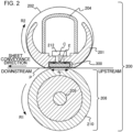
- FIG. 2 is a schematic sectional view of the fixing apparatus 200 as an image heating apparatus according to the embodiment.
- the fixing apparatus 200 has a fixing film 202, a heater 300 in contact with the inner surface of the fixing film 202, a pressure roller 208 which forms a fixing nip portion N together with the heater 300 through the fixing film 202, and a metal stay 204.
- the fixing film 202 is a multi-layer heat resisting film also referred to as an endless belt or an endless film and formed to have a tubular shape and includes a heat resisting resin such as polyimide or a metal such as stainless steel as a base layer.
- a releasing layer is formed by coating a surface of the fixing film 202 with a heat resisting resin with high releasability such as tetrafluoroethylene/perfluoro (alkyl vinyl ether) copolymer (PFA) in order to prevent toner from sticking or secure releasability from the recording material P.
- heat resisting rubber such as silicone rubber may be formed as an elastic layer between the base layer and the releasing layer.
- the pressure roller 208 has a core bar 209 of a material such as iron and aluminum and an elastic layer 210 of a material such as silicone rubber.
- the heater 300 is held by a heater holding member 201 of a heat resisting resin, and heating regions A 1 to A 7 (which will be detailed later) provided in the fixing nip portion N are heated to heat the fixing film 202.
- the heater holding member 201 also has a guiding function to guide the fixing film 202 to rotate.
- the heater 300 is provided with an electrode E on the opposite side (the back surface side) to the side on which the heater is in contact the inner surface of the fixing film 202, and the electrode E is supplied with power from an electric contact C.
- the metal stay 204 receives pressurizing force which is not shown and energizes the heater holding member 201 toward the pressure roller 208.
- a safety element 212 such as a thermo-switch and a temperature fuse activated to shut off power supplied to the heater 300 in response to abnormal heat generation by the heater 300 is provided to oppose the back surface side of the heater 300.
- the pressure roller 208 receives motive power from a motor 30 shown in FIG. 1 and rotates in the direction of the arrow R1.
- the fixing film 202 follows the rotation of the pressure roller 208 to rotate in the direction of the arrow R2.
- the recording material P is sandwiched at the fixing nip portion N and conveyed while being provided with heat from the fixing film 202, so that the unfixed toner image on the recording material P is fixed.
- grease with high heat resistance (not shown) is interposed between the heater 300 and the fixing film 202.
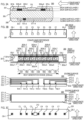
- FIG. 3A is a sectional view of the heater 300
- FIG. 3B is a plan view of the layers of the heater 300
- FIG. 3C is a view for illustrating a method for connecting the electric contact C to the heater 300.
- FIG. 3B indicates a conveyance reference position X for the recording material P in the image forming apparatus 100 according to the embodiment.
- the conveyance reference according to the embodiment is a center reference, and the recording material P is conveyed so that its center line in a direction orthogonal to the conveyance direction matches the conveyance reference position X.
- FIG. 3A is a sectional view of the heater 300 taken along the conveyance reference position X.
- the heater 300 includes a ceramic substrate 305, a back surface layer 1 provided on the substrate 305, a back surface layer 2 which covers the back surface layer 1, a sliding surface layer 1 provided at the surface opposite to the back surface layer 1 on the substrate 305, and a sliding surface layer 2 which covers the sliding surface layer 1.
- the back surface layer 1 has a conductor 301 (301a and 301b) provided in the lengthwise direction of the heater 300.
- the conductor 301 is divided into the conductors 301a and 301b, and the conductor 301b is provided downstream in the conveyance direction of the recording material P with respect to the conductor 301a on the substrate.
- the back surface layer 1 has conductors 303 (303-1 to 303-7) provided in parallel to the conductors 301a and 301b.
- the conductors 303 are provided in the lengthwise direction of the heater 300 between the conductors 301a and 301b.
- the back surface layer 1 has heat generating elements 302a (302a-1 to 302a-7) and heat generating elements 302b (302b-1 to 302b-7) as heat generating resistors which generates heat by conduction.
- the heat generating elements 302a are provided between the conductors 301a and 303 and supplied with power through the conductors 301a and 303 to generate heat.
- the heat generating element 302b is provided between the conductors 301b and 303 and supplied with power through the conductors 301b and 303 to generate heat.
- the heat generating part including the conductors 301 and 303 and the heat generating elements 302a and 302b is divided into seven heat generating blocks (HB 1 to HB 7 ) with respect to the lengthwise direction of the heater 300. More specifically, the heat generating element 302a is divided into seven regions, i.e., the heat generating elements 302a-1 to 302a-7 with respect to the lengthwise direction of the heater 300. The heat generating element 302b is divided into seven regions, i.e., the heat generating elements 302b-1 to 302b-7 with respect to the lengthwise direction of the heater 300.
- the conductor 303 is divided into seven regions, i.e., the conductors 303-1 to 303-7 corresponding to the dividing positions of the heat generating elements 302a and 302b.
- the amounts of power supplied to the heat generating resistors in the seven blocks (HB 1 to HB 7 ) are individually controlled, so that the heat generating quantity of the respective blocks are individually controlled.
- the heat generation range according to the embodiment is from the left end of the heat generating block HB 1 to the right end of the heat generating block HB 7 in the figure and the total length is 220 mm.
- the length of each of the heat generating blocks is equally about 31 mm, while the length may be different among the blocks.
- the back surface layer 1 has electrodes E (E1 to E7, E8-1 and E8-2).
- the electrodes E1 to E7 are provided in the regions of the conductors 303-1 to 303-7, respectively and serve to supply power to the heat generating blocks HB 1 to HB 7 through the conductors 303-1 to 303-7, respectively.
- the electrodes E8-1 and E8-2 are provided to be connected with the conductor 301 at the lengthwise ends of the heater 300 and serve to supply power to the heat generating blocks HB 1 to HB 7 through the conductor 301.
- the electrodes E8-1 and E8-2 are provided at the lengthwise ends of the heater 300 while for example only the electrode E8-1 may be provided at one end (without providing the electrode E8-2).
- a common electrode is used to supply power to the conductors 301a and 301b, while the conductors 301a and 301b may each be provided with an individual electrode and suppled with power.
- the back surface layer 2 includes an insulating surface protection layer 307 (of glass according to the embodiment) which covers the conductors 301 and 303 and the heat generating elements 302a and 302b.
- the surface protection layer 307 is formed for the region except for the location of electrodes E, and electric contacts C can be connected to the electrode E from the side of the back surface layer 2 of the heater.
- the sliding surface layer 1 is provided on the surface of the substrate 305 on the opposite side to the surface provided with the back surface layer 1 and has thermistors TH (TH1-1 to TH1-4 and TH2-5 to TH2-7) as detecting elements for detecting the temperatures of the heat generating blocks HB 1 to HB 7 .
- the thermistors TH are made of a material having a PTC characteristic or an NTC characteristic (the NTC characteristic according to the embodiment) and the temperatures of all the heat generating blocks can be detected by detecting the resistance values of the thermistors.
- the sliding surface layer 1 has conductors ET (ET1-1 to ET1-4 and ET2-5 to ET2-7) and conductors EG (EG1 and EG2) for passing current through the thermistors TH and detecting the resistance values.
- the conductors ET1-1 to ET1-4 are connected to the thermistors TH1-1 to TH1-4, respectively.
- the conductors ET2-5 to ET2-7 are connected to the thermistors TH2-5 to TH2-7, respectively.
- the conductor EG1 is connected to the four thermistors TH1-1 to TH1-4 to form a common conduction path.
- the conductor EG2 is connected to the three thermistors TH2-5 to TH2-7 to form a common conduction path.
- the conductor ET and the conductor EG are formed in the lengthwise direction of the heater 300 up to the lengthwise ends of the heater 300 and are connected with the control circuit 400 through electric contacts (not shown) at the lengthwise ends of the heater 300.
- the sliding surface layer 2 is made of a slidable insulating surface protection layer 308 (glass according to the embodiment), covers the thermistors TH, the conductors ET, and the conductors EG, and secures the slidability against the inner surface of the fixing film 202.
- the surface protection layer 308 is formed in the region except for the lengthwise ends of the heater 300 in order to provide electric contacts to the conductors ET and the conductors EG.
- FIG. 3C is a plan view of the electric contact C connected to each of the electrodes E as viewed from the side of the heater holding member 201.
- the heater holding member 201 is provided with through holes in positions corresponding to the electrodes E (E1 to E7 and E8-1 and E8-2).
- the electric contacts C (C1 to C7 and C8-1 and C8-2) are electrically connected to the electrodes E (E1 to E7 and E8-1 and E8-2) by energizing using a spring or welding in the positions of the through holes.
- the electric contacts C are connected to the control circuit 400 for the heater 300, which will be described, through a conductive material (not shown) provided between the metal stay 204 and the heater holding member 201.
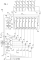
- FIG. 4 is a circuit diagram of the control circuit 400 for the heater 300 according to the first embodiment.
- the reference numeral 401 represents a commercially available AC power supply connected to the image forming apparatus 100.
- Power control for the heater 300 is carried out by conducting/shutting off triacs 411 to 417.
- the triacs 411 to 417 operate in response to FUSER1 to FUSER7 signals, respectively from a CPU 420.
- a driving circuit for the triacs 411 to 417 is not shown.
- the control circuit 400 for the heater 300 has a circuit configuration which allows the seven heat generating blocks HB 1 to HB 7 to be independently controlled by the seven triacs 411 to 417.
- a zero-crossing detecting portion 421 is a circuit which detects a zero-crossing of the AC power supply 401 and outputs a ZEROX signal to the CPU 420.
- the ZEROX signal is used to detect timing for phase control or wavenumber control for the triacs 411 to 417.
- a method for detecting the temperature of the heater 300 will be described.
- the temperature of the heater 300 is detected by the thermistors TH (TH1-1 to TH1-4 and TH2-5 to TH2-7).
- Fractional voltages across the thermistors TH1-1 to TH1-4 and resistors 451 to 454 are obtained as signals Th1-1 to Th1-4 by the CPU 420, and the signals Th1-1 to Th1-4 are converted into temperatures by the CPU 420.
- fractional voltages across the thermistors TH2-5 to TH2-7 and resistors 465 to 467 are obtained as signals Th2-5 to Th2-7 by the CPU 420, and the signals Th2-5 to Th2-7 are converted into temperatures by the CPU 420.
- power to be supplied is calculated by PI control (proportional integral control) on the basis of a control target temperature TGT i for each of the heat generating blocks and temperatures detected by the thermistors. Then, the power is converted into a phase angle (phase control) corresponding to the power or a wavenumber (wavenumber control) control level (a duty cycle) and the triacs 411 to 417 are controlled on the control conditions.
- PI control proportional integral control
- Relays 430 and 440 are used as power shutting off means for the heater 300 when the temperature of the heater 300 is excessively raised.
- the circuit operation of the relays 430 and 440 will be described.
- an RLON signal attains a high state
- a transistor 433 is turned on, and current is passed to the secondary side coil of the relay 430 from the power supply voltage Vcc, which turns on the primary side contact of the relay 430.
- the transistor 433 attains a low state, the transistor 433 is turned off, and current passed to the secondary side coil of the relay 430 from the power supply voltage Vcc is shut off, which turns off the primary side contact of the relay 430.
- resistors 434 and 444 are current limiting resistors.
- a comparing portion 431 activates a latch portion 432, and the latch portion 432 latches an RLOFF1 signal in a low state.
- the RLOFF1 signal attains a low state
- the CPU 420 makes the RLON signal attain a high state
- the transistor 433 is kept in an off state, so that the relay 430 can be kept in an off state (a safe state).
- the latch portion 432 allows the RLOFF1 signal to be output in an open state in a non-latch state.
- a comparing portion 441 causes the latch portion 442 to operate and latch an RLOFF2 signal in a low state.
- the RLOFF2 signal attains a low state, and even if the CPU 420 makes the RLON signal attain a high state, the transistor 443 is kept in an off state, so that the relay 440 can be kept in an off state (a safe state).
- the latch portion 442 allows the RLOFF2 signal to be output in an open state in a non-latch state.
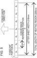
- FIG. 5 is a view of the heating regions A 1 to A 7 according to the embodiment shown in comparison with the width of the LETTER size sheet.
- the image forming apparatus changes a heat generating quantity for each of the heat generating blocks HB i according to image data (image information) transmitted from an external device (not shown) such as a host computer.
- image data image information
- an external device not shown
- a higher target temperature is set for a heat generating block HB i which heats a heating region A i corresponding to the low print percentage image.
- the start-up sequence is carried out to warm the fixing apparatus 200 to an appropriate temperature (hereinafter referred to as a start-up completion target temperature) for heating a recording material P and a toner image on the recording material P.
- a start-up completion target temperature an appropriate temperature for heating a recording material P and a toner image on the recording material P.
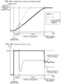
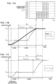
- FIG. 6A shows an example of the transition of the temperatures of heat generating blocks detected by the thermistors TH.
- the solid line represents the conduction duty cycle of the heat generating block HB min and the dotted line is the conduction duty cycle of the heat generating block HB other . While there are more than one heat generating blocks HB other , the temperature and the conduction duty cycle of one of the blocks are indicated as typical values.
- the length of the start-up requirement time for the heat generating blocks HB i (1 to 7) is determined as follows.
- the duty cycle is 100% (so-called full conduction).
- variations in the resistance values of the heat generating resistors in the heat generating blocks HB i cause variations in the power (or the heat generating quantity) of the heat generating blocks HB i .
- the resistance value As the resistance value is smaller, the power increases and thus the heat generating quantity increases, while as the resistance value is greater, the power is reduced and thus the heat generating quantity is reduced. As the heat generating quantity is smaller, the temperature is less easily raised, so that longer start-up time is required. Therefore, according to the embodiment, in timing a prescribed period after the start of supply of power with the fixed duty cycle, the temperatures of the heat generating blocks HB i are detected by the thermistors TH. Then, it is determined that the heat generating block HB i with the lowest temperature that requires the longest start-up time is the heat generating block HB min. When the heat generating block HB min which requires the longest start-up time is determined, the start-up sequence proceeds to the PI control section S1001.
- the PI control section S1001 (the second section), conduction control to the heat generating block HB min which requires the longest start-up time is carried out by PI control so that the temperature T min of the heat generating block HB min is approximated to the start-up completion target temperature.
- the temperature T min is sufficiently lower than the start-up completion target temperature, power is supplied with a duty cycle of 100%, and the conduction duty cycle is reduced by the PI control as T min is closer to the start-up completion target temperature.
- the recording material P having the toner image thereon is conveyed, and the start-up sequence proceeds to a sheet passing sequence.
- the start-up control parameter is a target temperature in the process of the start-up of the heat generating block HB other , which is changed sequentially during the start-up control with reference to the temperature T min representing the start-up performance of the heat generating block HB min .
- the temperature T other is higher than the temperature T min .
- the conduction duty cycle to the heat generating block HB other is thereafter reduced by the PI control, so that the heat generating block HB other can start up by a temperature transition similar to that in the heat generating block HB min .
- the temperatures of the heat generating blocks may be equalized before the start-up by the control according to the embodiment.
- a heat generating block having a small resistance value and a large heat generating quantity (hereinafter referred to as HB other according to the first comparative example) starts up earlier as indicated by the dash-dotted line in FIG. 6A and stands by for a transition to the sheet passing sequence while keeping the start-up completion target temperature. More specifically, the temperature transition according to the first comparative example varies among the heat generating blocks more greatly than the first embodiment.
- the heat generating block with early start-up as HB other according to the first comparative example is kept in a high temperature state for a longer period than a heat generating block with delayed start-up, and therefore the temperature of the part of the pressure roller 208 corresponding to the heat generating blocks is more easily raised. Therefore, with the variations in the temperature transition among the heat generating blocks as in the first comparative example, variations are likely to be generated in the temperature distribution of the pressure roller 208 after the start-up, and as a result, an image defect such as gloss value unevenness and hot offset may be generated.
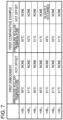
- the fixing apparatuses 200 according to the first embodiment and the first comparative example were cooled to room temperature and then a half-tone image was printed on a sheet.
- the surface temperature of the pressure roller 208 immediately after the start-up was measured by thermography and the print of the half-tone image was observed for hot offset. Note that the same fixing apparatus 200 was used as the fixing apparatus 200 for the first embodiment and as the fixing apparatus 200 for the first comparative example simply by changing control software.
- the result of the comparison experiment is given in FIG. 7 .
- the surface temperature of the pressure roller 208 varied within the range of 6°C, and slight hot offset was generated in the position corresponding to the heat generating block HB 5 having the highest temperature. Meanwhile, according to the first embodiment, the surface temperature of the pressure roller 208 according to the first embodiment varied within 1°C, and there was no hot offset.
- the start-up control according to the first embodiment is carried out, so that heating unevenness in the start-up and an image defect immediately after the start-up were restrained.
- the heat generating block HB min may be determined by a different method. For example, in the fixed duty cycle section S1000, the time period until a prescribed temperature is reached is measured, and the heat generating block with the longest time period may be determined as the heat generating block HB min .
- the gradient of the temperature rise over time may be calculated, and the heat generating block with the smallest gradient may be determined as the heat generating block HB min .
- the temperature rise for a prescribed time period or time required for a prescribed temperature rise may be measured to calculate the gradient of the temperature rise.
- Power detecting means for detecting the power of the plurality of heat generating blocks may be provided, and the heat generating block with the smallest power in the fixed duty cycle section S1000 may be determined as the heat generating block HB min .
- the start-up performance information once obtained for each of the heat generating blocks HB i may be stored, and the heat generating block HB min may be determined for the next printing operation on the basis of the stored start-up performance information.
- the heat generating block HB min may be stored and the information may be used for the next printing operation.
- the start-up requirement time or information on the start-up requirement time may be measured, and the heat generating block HB min may be determined using the information.
- the resistance values of the heat generating blocks are measured and stored by storage means provided at the fixing apparatus 200 or the image forming apparatus 100. Then, during the start-up operation of the fixing apparatus 200, the information stored in the storage means is read out, and the heat generating block with the lowest resistance value is determined as the heat generating block HB min .
- the storage means refers to anything capable of storing information such as a memory such as an NVRAM, an RFID such as an IC tag, and a barcode.
- the heat generating block which requires the longest start-up time may be determined any of the methods, so that heating unevenness during the start-up can be restrained and an image defect immediately after the start-up can be restrained similarly to the first embodiment.
- a second embodiment of the present invention will be described.
- the basic configuration and operation of an image forming apparatus and an image heating apparatus according to the second embodiment are the same as those of the first embodiment. Therefore, elements having functions and structures identical or corresponding to the first embodiment are designated by the same reference characters and their detailed description will not be repeated.
- the matters which will not be particularly described here in connection with the second embodiment are the same as those of the first embodiment.
- the second embodiment is different from the first embodiment in that the start-up control parameter (here, a target temperature for a heat generating block during the start-up) is changed according to a different reference.
- the start-up control parameter here, a target temperature for a heat generating block during the start-up
- the temperature T min is used as a reference
- the start-up speed of the heat generating block HB min is used as a reference.
- FIG. 8 shows an example of the transition of the temperature of a heat generating block detected by a thermistor TH and the transition of a target temperature.
- the start-up sequence according to the embodiment is divided into a section for supplying power with a fixed duty cycle (S1000) and a start-up section by PI control (S1002).
- the start-up speed TRR min (a temperature rise per unit time) is obtained for the heat generating block HB min .
- the start-up speed TRR min is a value representing the start-up performance of the heat generating block HB min according to the embodiment.
- the measurement starting time for the start-up speed TRR min is time 1
- the measurement ending time is time 2
- the temperature of the heat generating block HB min at time 1 is T min 1
- the temperature of the heat generating block HB min at time 2 is T min 2.
- the start-up speed TRR min is desirably measured a prescribed time period after the start of supply of power.
- the start-up sequence proceeds to the PI control section S1002.
- power supply control to the heat generating block HB min is carried out by the PI control so that the temperature T min of the heat generating block HB min is approximated to the start-up completion target temperature similarly to the first embodiment.
- power supply control to the heat generating block HB other is carried out by the PI control so that the temperature T other is approximated to the start-up target temperature curve obtained as follows with reference to the start-up speed TRR min .
- the start-up target temperature curve is provided by obtaining the starting point P s , the midpoint P m , and the ending point P e as follows and connecting between the starting point P s and the midpoint P m and between the midpoint P m and the ending point P e by straight lines.
- the target temperature T tgte at the ending point P e is the same temperature as the start-up completion target temperature.
- the start-up target temperature curve obtained with reference to the start-up speed TRR min of the heat generating block HB min indicates a transition substantially the same as the temperature T min of the heat generating block HB min . Therefore, the PI control is carried out so that the temperature T other of the heat generating block HB other is approximated to the temperature start-up target temperature curve, and the start-up can be carried out while the temperatures of the heat generating blocks are equal, so that the same advantageous effects as those of the first embodiment can be provided.
- the start-up control parameter is a conduction duty cycle for the heat generating block HB other , and the conduction duty cycle is changed so that the input power to the heat generating blocks HB i is equal by changing the conduction duty cycle, which is different from the first embodiment.
- S1000 fixed duty cycle
- S1003 start-up section
- the power W 100i is in other words power which can be input to each of the heat generating blocks HB i .
- power detecting means for detecting the power of the heat generating blocks is provided, and the power W 100i a prescribed time period after the start of supply of power is directly measured.
- the power supply control to the heat generating blocks HB i is carried out by the PI control so that the temperature T i of the heat generating block HB i is approximated to the start-up completion target temperature.
- the conduction duty cycle Pdh i is changed with reference to the power W 100min with the conduction duty cycle of 100% in the heat generating block HB min , and therefore input power can be equalized if the resistance values of the heat generating blocks HB i vary among the heat generating blocks HB i .
- the same advantageous effects as those of the first embodiment can be provided.
- a fourth embodiment of the present invention will be described.
- the basic configuration and operation of an image forming apparatus and an image heating apparatus according to the fourth embodiment are the same as those of the first embodiment. Therefore, elements having functions and structures identical to or corresponding to those of the first embodiment are designated by the same reference characters and their detailed description will not be repeated.
- the matters which will not be particularly described here in connection with the fourth embodiment are the same as those of the first embodiment.
- the fourth embodiment is different from the first embodiment in that power to be input to the heat generating blocks HB other is a start-up control parameter, and power to be input to the heat generating blocks HB i is adjusted to be equal.
- S1000 fixed duty cycle
- S1004 start-up section
- the operation of the fixed duty cycle section S1000 is the same as that of the first embodiment and will not be described.
- the start-up sequence proceeds to the PI control section S1004.
- power detecting means for detecting the power of each of the heat generating blocks is provided, and the power Wti is directly measured.
- power supply control to the heat generating block HB min is carried out by the PI control so that the temperature T min of the heat generating block HB min is approximated to the completion target temperature. Meanwhile, supply of power to the heat generating blocks HB other is controlled so that the power W tother during the start-up in the heat generating blocks HB other is approximated to W tmin .
- W tmin is power in the process of the start-up of the heat generating block HB min and a value representing the start-up performance of the heat generating block HB min according to the embodiment.
- the power W tother to be input to the heat generating blocks HB other is changed with reference to the power W tmin in the process of the start-up in the heat generating block HB min .
- input power during the start-up can be equalized if the resistance value varies among the heat generating blocks HB i .
- the heat generating blocks HB i can start up at the same temperature, so that the same advantageous effects as those of the first embodiment can be provided.
- a fifth embodiment of the present invention will be described.
- the basic configuration and operation of an image forming apparatus and an image heating apparatus according to the fifth embodiment are the same as those of the first embodiment. Therefore, elements having functions and structures identical or corresponding to those of the first embodiment are designated by the same reference characters and their detailed description will not be repeated.
- the matters which will not be particularly described here in connection with the fifth embodiment are the same as those of the first embodiment.
- the fifth embodiment is different from the first embodiment in that the starting timing for start-up is a start-up control parameter.
- FIG. 9 shows an example of the transition of the temperatures of heat generating blocks detected by thermistors TH.
- a prescribed primary start-up target temperature T tgtA is set to a lower temperature than a start-up completion target temperature T tgtB .
- the method for supplying power is switched to the PI control based method targeted to the temperature T tgtA .
- the start-up speed TRR i of each of the heat generating blocks HB i (the temperature rise amount per unit time) is obtained.
- the temperature rise amount is not stable, and therefore the start-up speed TRR i is desirably measured a prescribed time period after the start of supply of power.
- the power supply control to the heat generating blocks HB i is carried out by the PI control so that the temperature T i of the heat generating block HB i is approximated to the start-up completion target temperature T tgtB .
- the primary start-up target temperature T tgtA continues to be the target temperature.
- the secondary start-up delay time T wait_i is calculated as follows.
- W min represents the secondary start-up requirement time for the heat generating block HB min which requires the longest start-up time and a value representing the start-up performance of the heat generating block HB min .
- the difference between the secondary start-up requirement time W min of the heat generating block HB min as a reference and the secondary start-up requirement time for the heat generating block HB other i.e., the secondary start-up delay time T wait_i .
- the timing for starting raising the temperature in the secondary start-up section S1006 is changed. Since all the heat generating blocks HB i start up to attain the start-up completion target temperature T tgtB almost at a time, variations in the temperature distribution of the pressure roller 208 can be restrained as compared to the first comparative example. As a result, an image defect such as gloss value unevenness and hot offset may be reduced.
- the secondary start-up requirement time W i for each of the heat generating blocks HB i is obtained from the start-up speed TRR i of each of the heat generating block HB i
- the secondary start-up requirement time W i may be obtained by any other method. For example, if the relation between the power and the start-up speed is examined in advance, the start-up speed may be estimated from the power. Then, the power supply voltage is measured at the start of the start-up sequence, and power is calculated using the result and the previously calculated resistance value of each of the heat generating blocks, so that the secondary start-up requirement time Wi can be calculated. In this case, the secondary start-up requirement time Wi is already known at the initial point of the start-up sequence, and therefore the primary start-up section S1005 may be omitted.
- a sixth embodiment of the present invention will be described.
- the basic configuration and operation of an image forming apparatus and an image heating apparatus according to the sixth embodiment are the same as those of the fifth embodiment. Therefore, elements having functions and structures identical or corresponding to those of the fifth embodiment are designated by the same reference characters and their detailed description will not be repeated.
- the matters which will not be particularly described here in connection with the sixth embodiment are the same as those of the fifth embodiment.
- the sixth embodiment is different from the fifth embodiment in that the primary start-up target temperature is changed for each of the heat generating blocks.
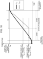
- FIG. 10 shown an example of the transition of the temperature of the heat generating blocks detected by thermistors TH.
- the method for supplying power to a heat generating block HB i for which a temperature detected by the thermistor TH reaches the primary start-up target temperature T tgtA_i is sequentially switched to the PI control targeted to the target temperature T tgtA_i .
- the start-up sequence proceeds to the secondary start-up section S1008. More specifically, the start-up speed of the heat generating block HB min which requires the longest start-up time is represented by TRR min , and the primary start-up target temperature is represented by T tgtA_min . In this case, transition timing to the secondary start-up section changes according T tgtA_min calculated on the basis of TRR min .
- the power supply control to each of the heat generating blocks HB i is carried out by the PI control so that the temperature T i of the heat generating block HB i is approximated to a start-up completion target temperature T tgtB .
- the primary start-up target temperature T tgtA_i is changed with reference to the start-up speed TRR i of each of the heat generating blocks HB i .
- the switching timing to the secondary start-up section S1006 is changed with reference to the start-up speed TRR min of the heat generating block HB min which requires the longest start-up time.
- the control allows all the heat generating blocks HB i to start up to attain the start-up completion target temperature T tgtB almost at a time, so that variations in the temperature distribution of the pressure roller 208 can be reduced as compared to the first comparative example. As a result, an image defect such as gloss value unevenness and hot offset can be reduced.
- FIG. 11A is a view showing the positional relation between an image to be printed and the heating regions A i according to the embodiment.
- the leading end position of the image with respect to the heating regions A 1 , A 2 , and A 3 is designated by p1 and the leading end position of the image with respect to the heating regions A 4 , A 5 , A 6 , and A 7 is designated by p2 which is positioned behind p1.
- the start-up of the heat generating blocks HB i is adjusted so that the start-up completion target temperature T tgtB is reached in timing with the arrival of the leading end position of the image at the fixing nip N.
- the start-up completion timing for the heat generating blocks HB 4 , HB 5 , HB 6 , and HB 7 for which the image leading end position is p2 is later than the start-up completion timing for the heat generating blocks HB 1 , HB 2 , and HB 3 for which the image leading end position is p1.
- the heat generating blocks for which the image leading end position is (HB 1 , HB 2 , and HB 3 according to the embodiment) among the heat generating blocks HB i are referred to as a group A.
- the heat generating blocks other than the group A (HB 4 , HB 5 , HB 6 , and HB 7 according to the embodiment) are referred to as a group B.
- FIG. 11B is a graph showing temperature transition at the start-up of the heat generating blocks which belong to the group A.
- the temperature T min of the heat generating block HB min which requires the longest start-up time in the group A is indicated by the solid line
- the temperature T other1 of the heat generating blocks collectively represented by HB other1 other than the heat generating block HB min is indicated by the dotted line.
- FIG. 11C is a graph showing temperature transition at the start-up of heat generating blocks which belong to the group B.
- the temperature T other2 of the plurality of heat generating blocks collectively represented by HB other2 is indicated by the dotted line.
- the primary start-up section S1005 is the same as that according to the fifth embodiment and therefore will be not described. After all the heat generating blocks HB i attain a prescribed primary start-up target temperature T tgtA , the start-up sequence proceeds to the secondary start-up section S1009.
- the secondary start-up delay time T wait_i is calculated as follows.
- W min represents the secondary start-up requirement time for the heat generating block HB min which requires the longest start-up time and a value representing the start-up performance of the heat generating block HB min according to the embodiment.
- the secondary start-up requirement time W i for the heat generating block HB other1 is indicated by W other1 .
- the secondary start-up requirement time W i for the heat generating block HB other2 is indicated by W other2 .
- T pos_i is delay time related to the image tip end position and corresponds to a period after the image leading end position of the group A reaches the fixing nip N until the image leading end position corresponding to each of the heat generating blocks HB i reaches the fixing nip N.
- the secondary start-up delay time T wait_i for the heat generating block HB other1 is indicated by T wait_other1 .
- the secondary start-up delay time T wait_i for the heat generating block HB other2 is indicated by T wait_other2 .
- the start-up control is carried out in consideration of the image leading end position, so that unnecessary heating before the arrival of the image can be reduced. As a result, an image defect such as gloss value unevenness and hot offsets can be reduced.
- an image with a low print percentage such as a half-tone image requires a higher heat value for fixing as compared to an image with a high print percentage such as a solid image. Therefore, the target temperature for the heat generating block HB i for heating the heating region A i corresponding to a low print percentage image is set to a higher value.
- the present invention may be applied by carrying out correction control corresponding to the start-up completion target temperature, and the advantageous effects can be provided.
- the start-up completion target temperature is low, only a small heat value is necessary for the start-up, and the target temperature can be reached more quickly. Therefore, when the length of the start-up requirement time is determined, correction can be carried out so that estimated start-up requirement time is smaller for a heat generating block HB i with a lower start-up completion target temperature.
- the temperature before the start-up can be different among the heat generating blocks HB i depending on the printing history.
- a warm heat generating block HB i to start with can attain a target temperature with a smaller heat value and more quickly. Therefore, when the length of the start-up requirement time is determined, correction can be carried out so that estimated start-up requirement time is smaller for a heat generating block HB i having a higher pre-start-up temperature.
- the start-up requirement time Wi is calculated by the above method, and estimated start-up requirement time Wi may be smaller for a higher pre-start-up temperature T tgtA_i and the estimated start-up requirement time W i may be smaller for a lower start-up completion target temperature T tgtB_i .
- the heating regions A i and the heat generating blocks HB i are obtained by division into seven equal parts as for the number of divisions and the dividing positions by way of illustration, while the advantageous effects of the invention may be provided by any of other configurations.
- dividing positions may correspond to the ends of the width of a regular size sheet such as a JIS B5 sheet (182 mm ⁇ 257 mm) and an A5 sheet (148 mm ⁇ 210 mm).
- the heat generating blocks HB i may have different lengths depending on the dividing positions.
- the heat generating blocks HB i are independently controlled in relation with heating, while some of the heat generating blocks HB i may be subjected to common control or dependent control.
- the heat generating blocks under the common control or dependent control are classified as a group (hereinafter referred to as a non-independent group).
- the average or lowest value of a parameter representing the start-up performance of the heat generating blocks in the non-independent group is obtained and set as a reprehensive value for the non-independent group.
- the parameter representing the start-up performance is a numerical value such as the power W 100i with a conduction duty cycle of 100%, the start-up requirement time W i , and the start-up speed TRR i on the basis of which the length of the start-up requirement time can be determined.
- the representative value of the non-independent group is compared to a parameter representing the start-up performance of an independently controllable heat generating block, and the length of the start-up requirement time is determined.
- the start-up control parameter of each of the heat generating block HB i may be adjusted with reference to the representative value for the start-up performance of the non-independent group. The same applies to the case in which a plurality of such non-independent groups are provided.
Landscapes
- Physics & Mathematics (AREA)
- General Physics & Mathematics (AREA)
- Engineering & Computer Science (AREA)
- Microelectronics & Electronic Packaging (AREA)
- Fixing For Electrophotography (AREA)
- Control Of Resistance Heating (AREA)
- Control Or Security For Electrophotography (AREA)
Applications Claiming Priority (1)
| Application Number | Priority Date | Filing Date | Title |
|---|---|---|---|
| JP2018011778A JP7062452B2 (ja) | 2018-01-26 | 2018-01-26 | 像加熱装置及び画像形成装置 |
Publications (2)
| Publication Number | Publication Date |
|---|---|
| EP3518049A1 EP3518049A1 (en) | 2019-07-31 |
| EP3518049B1 true EP3518049B1 (en) | 2024-11-13 |
Family
ID=65228411
Family Applications (1)
| Application Number | Title | Priority Date | Filing Date |
|---|---|---|---|
| EP19153428.8A Active EP3518049B1 (en) | 2018-01-26 | 2019-01-24 | Image heating apparatus and image forming apparatus |
Country Status (5)
| Country | Link |
|---|---|
| US (1) | US10691048B2 (enExample) |
| EP (1) | EP3518049B1 (enExample) |
| JP (1) | JP7062452B2 (enExample) |
| KR (2) | KR102332961B1 (enExample) |
| CN (1) | CN110083036B (enExample) |
Families Citing this family (3)
| Publication number | Priority date | Publication date | Assignee | Title |
|---|---|---|---|---|
| JP7362388B2 (ja) * | 2019-09-20 | 2023-10-17 | 東芝テック株式会社 | 画像形成装置、及び加熱方法 |
| JP7558672B2 (ja) | 2020-03-31 | 2024-10-01 | キヤノン株式会社 | 画像形成装置 |
| US11561493B1 (en) * | 2022-01-07 | 2023-01-24 | Toshiba Tec Kabushiki Kaisha | Temperature control device and image forming apparatus including temperature control device |
Family Cites Families (25)
| Publication number | Priority date | Publication date | Assignee | Title |
|---|---|---|---|---|
| JPH0695540A (ja) | 1992-09-11 | 1994-04-08 | Canon Inc | 加熱装置及び画像形成装置 |
| JPH08328425A (ja) * | 1995-05-31 | 1996-12-13 | Canon Inc | 定着装置及び画像形成装置 |
| JP2004020751A (ja) * | 2002-06-13 | 2004-01-22 | Sharp Corp | 加熱装置および加熱方法 |
| US6757503B2 (en) * | 2002-10-30 | 2004-06-29 | Kabushiki Kaisha Toshiba | Fixing device in an image forming apparatus having multiple heater lamps |
| JP2005234317A (ja) * | 2004-02-20 | 2005-09-02 | Canon Finetech Inc | 定着装置 |
| JP2005257746A (ja) * | 2004-03-09 | 2005-09-22 | Sharp Corp | 定着装置,画像形成装置 |
| JP2006113364A (ja) * | 2004-10-15 | 2006-04-27 | Canon Inc | 定着装置及び画像形成装置 |
| JP2007025237A (ja) | 2005-07-15 | 2007-02-01 | Ricoh Co Ltd | 定着装置及び画像形成装置 |
| KR100754206B1 (ko) * | 2006-02-10 | 2007-09-03 | 삼성전자주식회사 | 가열 롤러를 위한 전력 제어 방법 및 장치 |
| US8180240B2 (en) * | 2008-03-18 | 2012-05-15 | Lexmark International, Inc. | Color belt fuser warm-up time minimization |
| JP5327510B2 (ja) | 2008-06-25 | 2013-10-30 | 村田機械株式会社 | 画像形成装置 |
| JP2011197287A (ja) | 2010-03-18 | 2011-10-06 | Canon Inc | 画像形成装置 |
| JP5229275B2 (ja) | 2010-06-03 | 2013-07-03 | カシオ電子工業株式会社 | 定着温度制御装置、印刷装置、及び、プログラム |
| JP2012189770A (ja) | 2011-03-10 | 2012-10-04 | Ricoh Co Ltd | 定着装置及び画像形成装置 |
| JP5839839B2 (ja) * | 2011-05-19 | 2016-01-06 | キヤノン株式会社 | 定着装置 |
| JP2013246404A (ja) * | 2012-05-29 | 2013-12-09 | Canon Inc | 像加熱装置 |
| KR101992768B1 (ko) * | 2012-10-30 | 2019-06-27 | 휴렛-팩커드 디벨롭먼트 컴퍼니, 엘.피. | 정착장치와 이를 가지는 화상형성장치 |
| JP2014098737A (ja) * | 2012-11-13 | 2014-05-29 | Ricoh Co Ltd | 画像形成装置 |
| JP6213218B2 (ja) * | 2013-02-14 | 2017-10-18 | 株式会社リコー | 定着装置及び画像形成装置 |
| JP6111840B2 (ja) * | 2013-05-13 | 2017-04-12 | コニカミノルタ株式会社 | 画像形成装置 |
| JP2015072443A (ja) * | 2013-09-09 | 2015-04-16 | 株式会社リコー | 定着装置及び画像形成装置 |
| US10416598B2 (en) * | 2014-03-19 | 2019-09-17 | Canon Kabushiki Kaisha | Image heating apparatus and heater for use therein |
| JP6661311B2 (ja) * | 2015-09-11 | 2020-03-11 | キヤノン株式会社 | 像加熱装置及び像加熱装置に用いるヒータ |
| US10054882B2 (en) | 2016-07-01 | 2018-08-21 | Canon Kabushiki Kaisha | Image forming apparatus and image heating apparatus |
| JP6918450B2 (ja) | 2016-07-28 | 2021-08-11 | キヤノン株式会社 | 像加熱装置及び画像形成装置 |
-
2018
- 2018-01-26 JP JP2018011778A patent/JP7062452B2/ja active Active
-
2019
- 2019-01-22 CN CN201910055574.1A patent/CN110083036B/zh active Active
- 2019-01-24 EP EP19153428.8A patent/EP3518049B1/en active Active
- 2019-01-25 KR KR1020190009729A patent/KR102332961B1/ko active Active
- 2019-01-25 US US16/257,698 patent/US10691048B2/en active Active
-
2021
- 2021-11-25 KR KR1020210164353A patent/KR102383348B1/ko active Active
Also Published As
| Publication number | Publication date |
|---|---|
| CN110083036A (zh) | 2019-08-02 |
| KR20190091212A (ko) | 2019-08-05 |
| KR20210144646A (ko) | 2021-11-30 |
| CN110083036B (zh) | 2022-03-29 |
| EP3518049A1 (en) | 2019-07-31 |
| JP7062452B2 (ja) | 2022-05-06 |
| KR102332961B1 (ko) | 2021-11-30 |
| KR102383348B1 (ko) | 2022-04-08 |
| US10691048B2 (en) | 2020-06-23 |
| US20190235420A1 (en) | 2019-08-01 |
| JP2019128551A (ja) | 2019-08-01 |
Similar Documents
| Publication | Publication Date | Title |
|---|---|---|
| US10915046B2 (en) | Image heating apparatus and image forming apparatus | |
| US10649376B2 (en) | Image heating apparatus and image forming apparatus | |
| US11809104B2 (en) | Image heating apparatus and image formation apparatus with power supply control that sets a target temperature for each of a plurality of regions of recording material | |
| JP6827726B2 (ja) | 画像形成装置 | |
| US10429776B2 (en) | Image heating device including a controller that executes first and second heat controls based on temperatures detected by first and second detecting elements | |
| US11029627B2 (en) | Image heating apparatus and image forming apparatus | |
| KR102383348B1 (ko) | 화상 가열 장치 및 화상 형성 장치 | |
| JP2020013013A (ja) | 画像形成装置及び定着装置 | |
| JP6995526B2 (ja) | 像加熱装置及び画像形成装置 | |
| US11493865B2 (en) | Image heating device and image forming apparatus | |
| JP7277230B2 (ja) | 像加熱装置 | |
| US11198575B2 (en) | Image forming device that determines whether a recording material is in a skewed state | |
| US10969713B2 (en) | Image heating apparatus that controls plural heat generating blocks based on whether a recording material passes the respective block, and image forming apparatus | |
| JP2006010943A (ja) | 加熱装置 | |
| JP2009186752A (ja) | 画像形成装置 | |
| JP7081006B2 (ja) | 像加熱装置及び画像形成装置 | |
| JP7581042B2 (ja) | 像加熱装置及び画像形成装置 | |
| US20250291289A1 (en) | Image forming apparatus | |
| JP2011197287A (ja) | 画像形成装置 | |
| JP2019128385A (ja) | 画像形成装置 | |
| JP2023156013A (ja) | 像加熱装置および画像形成装置 | |
| JPH0683220A (ja) | 加熱定着装置及び画像形成装置 |
Legal Events
| Date | Code | Title | Description |
|---|---|---|---|
| PUAI | Public reference made under article 153(3) epc to a published international application that has entered the european phase |
Free format text: ORIGINAL CODE: 0009012 |
|
| STAA | Information on the status of an ep patent application or granted ep patent |
Free format text: STATUS: THE APPLICATION HAS BEEN PUBLISHED |
|
| AK | Designated contracting states |
Kind code of ref document: A1 Designated state(s): AL AT BE BG CH CY CZ DE DK EE ES FI FR GB GR HR HU IE IS IT LI LT LU LV MC MK MT NL NO PL PT RO RS SE SI SK SM TR |
|
| AX | Request for extension of the european patent |
Extension state: BA ME |
|
| STAA | Information on the status of an ep patent application or granted ep patent |
Free format text: STATUS: REQUEST FOR EXAMINATION WAS MADE |
|
| 17P | Request for examination filed |
Effective date: 20200131 |
|
| RBV | Designated contracting states (corrected) |
Designated state(s): AL AT BE BG CH CY CZ DE DK EE ES FI FR GB GR HR HU IE IS IT LI LT LU LV MC MK MT NL NO PL PT RO RS SE SI SK SM TR |
|
| STAA | Information on the status of an ep patent application or granted ep patent |
Free format text: STATUS: EXAMINATION IS IN PROGRESS |
|
| 17Q | First examination report despatched |
Effective date: 20220121 |
|
| GRAP | Despatch of communication of intention to grant a patent |
Free format text: ORIGINAL CODE: EPIDOSNIGR1 |
|
| STAA | Information on the status of an ep patent application or granted ep patent |
Free format text: STATUS: GRANT OF PATENT IS INTENDED |
|
| INTG | Intention to grant announced |
Effective date: 20240603 |
|
| GRAS | Grant fee paid |
Free format text: ORIGINAL CODE: EPIDOSNIGR3 |
|
| GRAA | (expected) grant |
Free format text: ORIGINAL CODE: 0009210 |
|
| STAA | Information on the status of an ep patent application or granted ep patent |
Free format text: STATUS: THE PATENT HAS BEEN GRANTED |
|
| AK | Designated contracting states |
Kind code of ref document: B1 Designated state(s): AL AT BE BG CH CY CZ DE DK EE ES FI FR GB GR HR HU IE IS IT LI LT LU LV MC MK MT NL NO PL PT RO RS SE SI SK SM TR |
|
| REG | Reference to a national code |
Ref country code: GB Ref legal event code: FG4D |
|
| REG | Reference to a national code |
Ref country code: CH Ref legal event code: EP |
|
| REG | Reference to a national code |
Ref country code: IE Ref legal event code: FG4D |
|
| REG | Reference to a national code |
Ref country code: DE Ref legal event code: R096 Ref document number: 602019061815 Country of ref document: DE |
|
| REG | Reference to a national code |
Ref country code: LT Ref legal event code: MG9D |
|
| REG | Reference to a national code |
Ref country code: NL Ref legal event code: MP Effective date: 20241113 |
|
| PG25 | Lapsed in a contracting state [announced via postgrant information from national office to epo] |
Ref country code: HR Free format text: LAPSE BECAUSE OF FAILURE TO SUBMIT A TRANSLATION OF THE DESCRIPTION OR TO PAY THE FEE WITHIN THE PRESCRIBED TIME-LIMIT Effective date: 20241113 Ref country code: IS Free format text: LAPSE BECAUSE OF FAILURE TO SUBMIT A TRANSLATION OF THE DESCRIPTION OR TO PAY THE FEE WITHIN THE PRESCRIBED TIME-LIMIT Effective date: 20250313 Ref country code: PT Free format text: LAPSE BECAUSE OF FAILURE TO SUBMIT A TRANSLATION OF THE DESCRIPTION OR TO PAY THE FEE WITHIN THE PRESCRIBED TIME-LIMIT Effective date: 20250313 |
|
| PGFP | Annual fee paid to national office [announced via postgrant information from national office to epo] |
Ref country code: DE Payment date: 20241218 Year of fee payment: 7 |
|
| PG25 | Lapsed in a contracting state [announced via postgrant information from national office to epo] |
Ref country code: FI Free format text: LAPSE BECAUSE OF FAILURE TO SUBMIT A TRANSLATION OF THE DESCRIPTION OR TO PAY THE FEE WITHIN THE PRESCRIBED TIME-LIMIT Effective date: 20241113 Ref country code: NL Free format text: LAPSE BECAUSE OF FAILURE TO SUBMIT A TRANSLATION OF THE DESCRIPTION OR TO PAY THE FEE WITHIN THE PRESCRIBED TIME-LIMIT Effective date: 20241113 |
|
| REG | Reference to a national code |
Ref country code: AT Ref legal event code: MK05 Ref document number: 1742130 Country of ref document: AT Kind code of ref document: T Effective date: 20241113 |
|
| PG25 | Lapsed in a contracting state [announced via postgrant information from national office to epo] |
Ref country code: BG Free format text: LAPSE BECAUSE OF FAILURE TO SUBMIT A TRANSLATION OF THE DESCRIPTION OR TO PAY THE FEE WITHIN THE PRESCRIBED TIME-LIMIT Effective date: 20241113 |
|
| PG25 | Lapsed in a contracting state [announced via postgrant information from national office to epo] |
Ref country code: ES Free format text: LAPSE BECAUSE OF FAILURE TO SUBMIT A TRANSLATION OF THE DESCRIPTION OR TO PAY THE FEE WITHIN THE PRESCRIBED TIME-LIMIT Effective date: 20241113 |
|
| PG25 | Lapsed in a contracting state [announced via postgrant information from national office to epo] |
Ref country code: NO Free format text: LAPSE BECAUSE OF FAILURE TO SUBMIT A TRANSLATION OF THE DESCRIPTION OR TO PAY THE FEE WITHIN THE PRESCRIBED TIME-LIMIT Effective date: 20250213 |
|
| PG25 | Lapsed in a contracting state [announced via postgrant information from national office to epo] |
Ref country code: LV Free format text: LAPSE BECAUSE OF FAILURE TO SUBMIT A TRANSLATION OF THE DESCRIPTION OR TO PAY THE FEE WITHIN THE PRESCRIBED TIME-LIMIT Effective date: 20241113 Ref country code: GR Free format text: LAPSE BECAUSE OF FAILURE TO SUBMIT A TRANSLATION OF THE DESCRIPTION OR TO PAY THE FEE WITHIN THE PRESCRIBED TIME-LIMIT Effective date: 20250214 Ref country code: AT Free format text: LAPSE BECAUSE OF FAILURE TO SUBMIT A TRANSLATION OF THE DESCRIPTION OR TO PAY THE FEE WITHIN THE PRESCRIBED TIME-LIMIT Effective date: 20241113 |
|
| PG25 | Lapsed in a contracting state [announced via postgrant information from national office to epo] |
Ref country code: PL Free format text: LAPSE BECAUSE OF FAILURE TO SUBMIT A TRANSLATION OF THE DESCRIPTION OR TO PAY THE FEE WITHIN THE PRESCRIBED TIME-LIMIT Effective date: 20241113 |
|
| PG25 | Lapsed in a contracting state [announced via postgrant information from national office to epo] |
Ref country code: RS Free format text: LAPSE BECAUSE OF FAILURE TO SUBMIT A TRANSLATION OF THE DESCRIPTION OR TO PAY THE FEE WITHIN THE PRESCRIBED TIME-LIMIT Effective date: 20250213 |
|
| PG25 | Lapsed in a contracting state [announced via postgrant information from national office to epo] |
Ref country code: SM Free format text: LAPSE BECAUSE OF FAILURE TO SUBMIT A TRANSLATION OF THE DESCRIPTION OR TO PAY THE FEE WITHIN THE PRESCRIBED TIME-LIMIT Effective date: 20241113 |
|
| PG25 | Lapsed in a contracting state [announced via postgrant information from national office to epo] |
Ref country code: DK Free format text: LAPSE BECAUSE OF FAILURE TO SUBMIT A TRANSLATION OF THE DESCRIPTION OR TO PAY THE FEE WITHIN THE PRESCRIBED TIME-LIMIT Effective date: 20241113 |
|
| PG25 | Lapsed in a contracting state [announced via postgrant information from national office to epo] |
Ref country code: EE Free format text: LAPSE BECAUSE OF FAILURE TO SUBMIT A TRANSLATION OF THE DESCRIPTION OR TO PAY THE FEE WITHIN THE PRESCRIBED TIME-LIMIT Effective date: 20241113 |
|
| PG25 | Lapsed in a contracting state [announced via postgrant information from national office to epo] |
Ref country code: RO Free format text: LAPSE BECAUSE OF FAILURE TO SUBMIT A TRANSLATION OF THE DESCRIPTION OR TO PAY THE FEE WITHIN THE PRESCRIBED TIME-LIMIT Effective date: 20241113 |
|
| PG25 | Lapsed in a contracting state [announced via postgrant information from national office to epo] |
Ref country code: SK Free format text: LAPSE BECAUSE OF FAILURE TO SUBMIT A TRANSLATION OF THE DESCRIPTION OR TO PAY THE FEE WITHIN THE PRESCRIBED TIME-LIMIT Effective date: 20241113 |
|
| PG25 | Lapsed in a contracting state [announced via postgrant information from national office to epo] |
Ref country code: CZ Free format text: LAPSE BECAUSE OF FAILURE TO SUBMIT A TRANSLATION OF THE DESCRIPTION OR TO PAY THE FEE WITHIN THE PRESCRIBED TIME-LIMIT Effective date: 20241113 |
|
| PG25 | Lapsed in a contracting state [announced via postgrant information from national office to epo] |
Ref country code: IT Free format text: LAPSE BECAUSE OF FAILURE TO SUBMIT A TRANSLATION OF THE DESCRIPTION OR TO PAY THE FEE WITHIN THE PRESCRIBED TIME-LIMIT Effective date: 20241113 |
|
| REG | Reference to a national code |
Ref country code: DE Ref legal event code: R097 Ref document number: 602019061815 Country of ref document: DE |
|
| REG | Reference to a national code |
Ref country code: CH Ref legal event code: PL |
|
| PG25 | Lapsed in a contracting state [announced via postgrant information from national office to epo] |
Ref country code: SE Free format text: LAPSE BECAUSE OF FAILURE TO SUBMIT A TRANSLATION OF THE DESCRIPTION OR TO PAY THE FEE WITHIN THE PRESCRIBED TIME-LIMIT Effective date: 20241113 |
|
| PG25 | Lapsed in a contracting state [announced via postgrant information from national office to epo] |
Ref country code: MC Free format text: LAPSE BECAUSE OF FAILURE TO SUBMIT A TRANSLATION OF THE DESCRIPTION OR TO PAY THE FEE WITHIN THE PRESCRIBED TIME-LIMIT Effective date: 20241113 Ref country code: LU Free format text: LAPSE BECAUSE OF NON-PAYMENT OF DUE FEES Effective date: 20250124 |
|
| PLBE | No opposition filed within time limit |
Free format text: ORIGINAL CODE: 0009261 |
|
| STAA | Information on the status of an ep patent application or granted ep patent |
Free format text: STATUS: NO OPPOSITION FILED WITHIN TIME LIMIT |
|
| PG25 | Lapsed in a contracting state [announced via postgrant information from national office to epo] |
Ref country code: BE Free format text: LAPSE BECAUSE OF NON-PAYMENT OF DUE FEES Effective date: 20250131 |
|
| PG25 | Lapsed in a contracting state [announced via postgrant information from national office to epo] |
Ref country code: FR Free format text: LAPSE BECAUSE OF NON-PAYMENT OF DUE FEES Effective date: 20250131 |
|
| PG25 | Lapsed in a contracting state [announced via postgrant information from national office to epo] |
Ref country code: CH Free format text: LAPSE BECAUSE OF NON-PAYMENT OF DUE FEES Effective date: 20250131 |
|
| 26N | No opposition filed |
Effective date: 20250814 |
|
| REG | Reference to a national code |
Ref country code: BE Ref legal event code: MM Effective date: 20250131 |
|
| GBPC | Gb: european patent ceased through non-payment of renewal fee |
Effective date: 20250213 |