EP3517632A1 - Method for operating blast furnace - Google Patents
Method for operating blast furnace Download PDFInfo
- Publication number
- EP3517632A1 EP3517632A1 EP17879791.6A EP17879791A EP3517632A1 EP 3517632 A1 EP3517632 A1 EP 3517632A1 EP 17879791 A EP17879791 A EP 17879791A EP 3517632 A1 EP3517632 A1 EP 3517632A1
- Authority
- EP
- European Patent Office
- Prior art keywords
- blast furnace
- sintered ore
- ore
- feed materials
- component concentrations
- Prior art date
- Legal status (The legal status is an assumption and is not a legal conclusion. Google has not performed a legal analysis and makes no representation as to the accuracy of the status listed.)
- Granted
Links
- 238000000034 method Methods 0.000 title claims abstract description 29
- 239000000463 material Substances 0.000 claims abstract description 113
- 238000005245 sintering Methods 0.000 claims abstract description 48
- XEEYBQQBJWHFJM-UHFFFAOYSA-N Iron Chemical compound [Fe] XEEYBQQBJWHFJM-UHFFFAOYSA-N 0.000 claims abstract description 45
- 239000002994 raw material Substances 0.000 claims abstract description 28
- 238000007873 sieving Methods 0.000 claims abstract description 24
- 229910052742 iron Inorganic materials 0.000 claims abstract description 22
- 238000001816 cooling Methods 0.000 claims abstract description 8
- ODINCKMPIJJUCX-UHFFFAOYSA-N calcium oxide Inorganic materials [Ca]=O ODINCKMPIJJUCX-UHFFFAOYSA-N 0.000 claims description 37
- VYPSYNLAJGMNEJ-UHFFFAOYSA-N Silicium dioxide Chemical compound O=[Si]=O VYPSYNLAJGMNEJ-UHFFFAOYSA-N 0.000 claims description 36
- 239000000377 silicon dioxide Substances 0.000 claims description 18
- 229910052681 coesite Inorganic materials 0.000 claims description 17
- 229910052906 cristobalite Inorganic materials 0.000 claims description 17
- CPLXHLVBOLITMK-UHFFFAOYSA-N magnesium oxide Inorganic materials [Mg]=O CPLXHLVBOLITMK-UHFFFAOYSA-N 0.000 claims description 17
- 229910052682 stishovite Inorganic materials 0.000 claims description 17
- 229910052905 tridymite Inorganic materials 0.000 claims description 17
- 239000008188 pellet Substances 0.000 claims description 11
- PNEYBMLMFCGWSK-UHFFFAOYSA-N aluminium oxide Inorganic materials [O-2].[O-2].[O-2].[Al+3].[Al+3] PNEYBMLMFCGWSK-UHFFFAOYSA-N 0.000 claims description 10
- 229910052593 corundum Inorganic materials 0.000 claims description 10
- 229910001845 yogo sapphire Inorganic materials 0.000 claims description 10
- UQSXHKLRYXJYBZ-UHFFFAOYSA-N iron oxide Inorganic materials [Fe]=O UQSXHKLRYXJYBZ-UHFFFAOYSA-N 0.000 claims description 9
- 239000000047 product Substances 0.000 description 63
- 239000000571 coke Substances 0.000 description 32
- 239000002245 particle Substances 0.000 description 24
- 230000000052 comparative effect Effects 0.000 description 22
- 239000010410 layer Substances 0.000 description 20
- 239000000292 calcium oxide Substances 0.000 description 19
- 235000012255 calcium oxide Nutrition 0.000 description 18
- 239000007789 gas Substances 0.000 description 17
- 238000005259 measurement Methods 0.000 description 13
- 239000002893 slag Substances 0.000 description 13
- 239000000395 magnesium oxide Substances 0.000 description 9
- 238000004519 manufacturing process Methods 0.000 description 8
- 238000004458 analytical method Methods 0.000 description 7
- 238000005516 engineering process Methods 0.000 description 7
- 239000002344 surface layer Substances 0.000 description 6
- 230000000717 retained effect Effects 0.000 description 5
- VNWKTOKETHGBQD-UHFFFAOYSA-N methane Chemical compound C VNWKTOKETHGBQD-UHFFFAOYSA-N 0.000 description 4
- 238000006243 chemical reaction Methods 0.000 description 3
- XLYOFNOQVPJJNP-UHFFFAOYSA-N water Substances O XLYOFNOQVPJJNP-UHFFFAOYSA-N 0.000 description 3
- VTYYLEPIZMXCLO-UHFFFAOYSA-L Calcium carbonate Chemical compound [Ca+2].[O-]C([O-])=O VTYYLEPIZMXCLO-UHFFFAOYSA-L 0.000 description 2
- PXHVJJICTQNCMI-UHFFFAOYSA-N Nickel Chemical compound [Ni] PXHVJJICTQNCMI-UHFFFAOYSA-N 0.000 description 2
- ATUOYWHBWRKTHZ-UHFFFAOYSA-N Propane Chemical compound CCC ATUOYWHBWRKTHZ-UHFFFAOYSA-N 0.000 description 2
- 230000007423 decrease Effects 0.000 description 2
- 230000006866 deterioration Effects 0.000 description 2
- 238000010586 diagram Methods 0.000 description 2
- 238000009826 distribution Methods 0.000 description 2
- 230000000694 effects Effects 0.000 description 2
- 239000000446 fuel Substances 0.000 description 2
- 230000000670 limiting effect Effects 0.000 description 2
- 230000035699 permeability Effects 0.000 description 2
- 230000002829 reductive effect Effects 0.000 description 2
- -1 serpentinite Substances 0.000 description 2
- MYMOFIZGZYHOMD-UHFFFAOYSA-N Dioxygen Chemical compound O=O MYMOFIZGZYHOMD-UHFFFAOYSA-N 0.000 description 1
- OTMSDBZUPAUEDD-UHFFFAOYSA-N Ethane Chemical compound CC OTMSDBZUPAUEDD-UHFFFAOYSA-N 0.000 description 1
- 235000019738 Limestone Nutrition 0.000 description 1
- RHZUVFJBSILHOK-UHFFFAOYSA-N anthracen-1-ylmethanolate Chemical compound C1=CC=C2C=C3C(C[O-])=CC=CC3=CC2=C1 RHZUVFJBSILHOK-UHFFFAOYSA-N 0.000 description 1
- 239000003830 anthracite Substances 0.000 description 1
- 229910000019 calcium carbonate Inorganic materials 0.000 description 1
- AXCZMVOFGPJBDE-UHFFFAOYSA-L calcium dihydroxide Chemical compound [OH-].[OH-].[Ca+2] AXCZMVOFGPJBDE-UHFFFAOYSA-L 0.000 description 1
- 239000000920 calcium hydroxide Substances 0.000 description 1
- 229910001861 calcium hydroxide Inorganic materials 0.000 description 1
- 239000003575 carbonaceous material Substances 0.000 description 1
- 230000015556 catabolic process Effects 0.000 description 1
- 239000003638 chemical reducing agent Substances 0.000 description 1
- 238000002485 combustion reaction Methods 0.000 description 1
- 150000001875 compounds Chemical class 0.000 description 1
- 230000003247 decreasing effect Effects 0.000 description 1
- 238000006731 degradation reaction Methods 0.000 description 1
- 230000003292 diminished effect Effects 0.000 description 1
- 229910001882 dioxygen Inorganic materials 0.000 description 1
- 238000007599 discharging Methods 0.000 description 1
- 239000010459 dolomite Substances 0.000 description 1
- 229910000514 dolomite Inorganic materials 0.000 description 1
- 239000000428 dust Substances 0.000 description 1
- 238000005469 granulation Methods 0.000 description 1
- 230000003179 granulation Effects 0.000 description 1
- 230000002401 inhibitory effect Effects 0.000 description 1
- 239000006028 limestone Substances 0.000 description 1
- 238000002844 melting Methods 0.000 description 1
- 230000008018 melting Effects 0.000 description 1
- 239000000203 mixture Substances 0.000 description 1
- 239000003345 natural gas Substances 0.000 description 1
- 229910052759 nickel Inorganic materials 0.000 description 1
- 239000001294 propane Substances 0.000 description 1
- 238000007670 refining Methods 0.000 description 1
- 238000004513 sizing Methods 0.000 description 1
- 239000004449 solid propellant Substances 0.000 description 1
- 239000004575 stone Substances 0.000 description 1
- 239000000126 substance Substances 0.000 description 1
- 239000013589 supplement Substances 0.000 description 1
- 238000004876 x-ray fluorescence Methods 0.000 description 1
Images


Classifications
-
- C—CHEMISTRY; METALLURGY
- C21—METALLURGY OF IRON
- C21B—MANUFACTURE OF IRON OR STEEL
- C21B5/00—Making pig-iron in the blast furnace
- C21B5/006—Automatically controlling the process
-
- C—CHEMISTRY; METALLURGY
- C21—METALLURGY OF IRON
- C21B—MANUFACTURE OF IRON OR STEEL
- C21B5/00—Making pig-iron in the blast furnace
- C21B5/008—Composition or distribution of the charge
-
- C—CHEMISTRY; METALLURGY
- C22—METALLURGY; FERROUS OR NON-FERROUS ALLOYS; TREATMENT OF ALLOYS OR NON-FERROUS METALS
- C22B—PRODUCTION AND REFINING OF METALS; PRETREATMENT OF RAW MATERIALS
- C22B1/00—Preliminary treatment of ores or scrap
- C22B1/14—Agglomerating; Briquetting; Binding; Granulating
- C22B1/16—Sintering; Agglomerating
- C22B1/20—Sintering; Agglomerating in sintering machines with movable grates
-
- C—CHEMISTRY; METALLURGY
- C21—METALLURGY OF IRON
- C21B—MANUFACTURE OF IRON OR STEEL
- C21B2100/00—Handling of exhaust gases produced during the manufacture of iron or steel
- C21B2100/80—Interaction of exhaust gases produced during the manufacture of iron or steel with other processes
Definitions
- the present invention relates to a blast furnace operation method involving adjusting consumptions of blast furnace feed materials, and in particular, to a blast furnace operation method involving measuring component concentrations of sintered ore, which is a blast furnace feed material, and using the component concentrations to adjust consumptions of blast furnace feed materials.
- iron-bearing materials such as sintered ore, lump iron ore and pellets are mainly used as iron sources for blast furnace feed materials.
- Sintered ore is a type of agglomerated ore and is obtained as follows.
- CaO- bearing materials such as limestone, quick lime, and slags
- auxiliary materials serving as a SiO 2 source or a MgO source such as silica stone, serpentinite, dolomite, and nickel refining slags
- a solid fuel (carbonaceous material) serving as a binding material such as coke breeze and anthracite
- Variations in the component concentrations of a sintering raw material lead to variations in the component concentrations of sintered ore, which is a product.
- the component concentrations of a material that is charged into a blast furnace are consistently managed for the purpose of controlling the quality of slags, for example. If a component concentration increases, another component needs to be added as an auxiliary material to dilute the component concentration. It is, therefore, necessary to quickly detect a change in component concentrations of sintered ore, lump iron ore, and pellets.
- Lump iron ore and pellets are products themselves, and, therefore, analysis of component concentrations is performed when, for example, products are unloaded.
- sintered ore however, no online analysis of component concentrations is currently performed, and the current situation is that analysis of component concentrations is very seldom performed.
- Patent Literature 1 discloses a technology in which the reducibility and the reduction degradation property of product sintered ore are predicted from the sintering raw material filling status, and, a consumption of a sintering raw material, rather than a consumption ratio for blast furnace feed materials, is adjusted to adjust the blast furnace feed materials.
- Patent Literature 2 discloses a technology in which FeO in product sintered ore is measured, and, on the basis of the difference from an aimed target value, the binding material for the sintering raw material, the water content for granulation, and the amount of exhaust air are adjusted.
- Patent Literature 3 discloses a technology in which, similarly, FeO in product sintered ore is measured, and, on the basis of the difference from an aimed target value, the amount of city gas to be injected into a sintering machine is adjusted.
- Patent Literature 4 discloses a technology in which the components of product sintered ore are estimated on the basis of the components in a surface layer of a sintering raw material, which are determined by a laser-type component analyzer provided on a sintering machine, and, a sintering raw material is formulated in a manner that reflects the estimate.
- Patent Literature 1 to Patent Literature 4 are technologies in which a particular component concentration of sintered ore is measured and, by using the measured component concentration, the sintering raw material is adjusted or the conditions for producing sintered ore are adjusted. None of Patent Literature 1 to Patent Literature 4 discloses adjusting, by using a measured component concentration of sintered ore, the consumptions of blast furnace feed materials to be charged into a blast furnace. Since the component concentrations of sintered ore can also change with the heat level during the sintering reaction, inhibiting changes in the component concentrations of a sintering raw material does not necessarily inhibit changes in the component concentrations of sintered ore.
- the present invention was made in view of such problems of the related art, and an object of the present invention is to provide a blast furnace operation method that makes it possible to control the component concentrations of blast furnace feed materials to target component concentrations even if there is a change in the component concentrations of a sintering raw material.
- the component concentrations of blast furnace feed materials can be controlled to target component concentrations. Consequently, changes in the viscosity of blast furnace slags, for example, are inhibited, which contributes to stable operation of a blast furnace.
- a measuring step for measuring component concentrations of sintered ore is provided, and component concentrations of sintered ore are measured in the measuring step.
- the consumptions of product sintered ore, pellets, lump iron ore, and an auxiliary material, which are blast furnace feed materials are adjusted. Consequently, the component concentrations of blast furnace feed materials can be controlled to reach target component concentrations, and as a result, stable blast furnace operation is made possible. With this finding, the present invention was made. The present invention will now be described with reference to an embodiment of the present invention.
- FIG. 1 is a schematic diagram illustrating an example of a sintered ore production apparatus 10, which can implement a blast furnace operation method according to the present embodiment.
- a sintered ore production apparatus 10 includes a sintering machine 12, a primary crusher 14, a cooler 16, a secondary crusher 18, a plurality of sieving devices 20, 22, 24, 26, an infrared analyzer 28, a product line 30, and a return ore line 32.
- the sintering machine 12 performs a sintering step.
- the sintering machine 12 is, for example, a downward-suction-type Dwight-Lloyd sintering machine.
- the sintering machine 12 includes a sintering raw material feeding device, an endless-moving-type pallet, an ignition furnace, and wind boxes.
- a sintering raw material is charged into the pallet through the sintering raw material feeding device, thereby forming a burden layer of the sintering raw material.
- the ignition furnace ignites the burden layer. Air within the burden layer is sucked downwardly through the wind boxes, thereby moving the combustion and melting zone within the burden layer toward a lower portion in the burden layer.
- the burden layer is sintered to form a sintered cake.
- a gas fuel and/or oxygen-gas-enriched air may be supplied from above the burden layer.
- the gas fuel is a combustible gas selected from the following: blast furnace gas, coke oven gas, a mixed gas of a blast furnace gas and coke oven gas, converter gas, city gas, natural gas, methane gas, ethane gas, propane gas, and a mixed gas thereof.
- the primary crusher 14 performs a crushing step.
- a sintered cake is crushed by the primary crusher 14 to form sintered ore.
- the cooler 16 performs a cooling step. Sintered ore is cooled by the cooler 16 to form cooled sintered ore.
- the sieving devices 20, 22, 24, 26 perform a sieving step.
- cooled sintered ore is sieved and separated into sintered ore having particle sizes greater than 75 mm and sintered ore having particle sizes less than or equal to 75 mm.
- particle sizes refers to particle sizes determined by performing sieving with a sieve: for example, “sintered ore having particle sizes greater than 75 mm” refers to particle sizes such that sintered ore, when sieved with a sieve having an opening size of 75 mm, is retained on the sieve, and “sintered ore having particle sizes less than or equal to 75 mm” refers to particle sizes such that sintered ore, when sieved with a sieve having an opening size of 75 mm, is not retained on the sieve.
- Sintered ore having particle sizes greater than 75 mm which is retained on the sieve when sieved with the sieving device 20, is crushed with the secondary crusher 18 to reduce the particle sizes to less than or equal to 50 mm.
- the crushed sintered ore is mixed with non-retained sintered ore, and the mixture is sieved with the sieving device 22. This ensures that the upper limit of the particle sizes of product sintered ore is not greater than 75 mm.
- Sintered ore having particle sizes less than or equal to 75 mm which is not retained on the sieve when sieved with the sieving device 20, is subsequently sieved and separated, by using the sieving devices 22, 24, 26, into product sintered ore having particle sizes greater than 5 mm and return ore having particle sizes less than or equal to 5 mm.
- Product sintered ore, which is sieved and separated with the sieving devices 22, 24 and 26, is transferred to a blast furnace 34 by a conveyor belt that forms the product line 30.
- return ore which is sieved and separated with the sieving devices 22, 24 and 26, is transferred to the sintering raw material feeding device of the sintering machine 12 again by a conveyor belt that forms the return ore line 32.
- the conveyor belt that forms the product line 30 is provided with the infrared analyzer 28.
- the infrared analyzer 28 performs the measuring step. In the measuring step, the component concentration of at least one of total CaO, SiO 2 , MgO, Al 2 O 3 , and FeO that are present in product sintered ore are measured.
- the infrared analyzer 28 radiates infrared light having wavelengths ranging from 0.5 ⁇ m to 50.0 ⁇ m onto sintered ore and receives reflected light from the sintered ore.
- Total CaO is determined by calculating Ca in all compounds including Ca and O, such as CaO, CaCO 3 , Ca(OH) 2 , and Fe 2 CaO 4 , as CaO.
- the infrared analyzer 28 radiates infrared light having 20 or more wavelengths and receives reflected light reflected from sintered ore, at a frequency of 128 times per minute. By radiating infrared light in a short time as described above, the infrared analyzer 28 can measure, on-line and sequentially, the component concentrations of sintered ore, which is transferred on the conveyor belt that forms the product line 30.
- the infrared analyzer 28 is an example of a component analysis instrument.
- the component analysis instrument is not limited to an instrument of the type that spectrally analyzes reflected light and may be an instrument of the type that spectrally analyzes transmitted light.
- infrared analyzer 28 it is possible to use a laser analyzer that radiates laser beams onto an object to be measured, a neutron analyzer that radiates neutrons onto an object to be measured, or a microwave analyzer that radiates microwaves onto an object to be measured.
- the product sintered ore is transferred to the blast furnace 34, and is subjected to an adjusting step in which the consumptions of blast furnace feed materials including product sintered ore, pellets, lump iron ore, and an auxiliary material are adjusted.
- the blast furnace feed materials may include one or more other materials in addition to the materials mentioned above or may not include pellets.
- the total component amounts of the blast furnace feed materials are calculated by using the component concentrations of the product sintered ore measured using the infrared analyzer 28 and premeasured component concentrations of pellets, lump iron ore, and an auxiliary material, and, by using the calculated value, feed-forward control is performed on the consumptions of the blast furnace feed materials to obtain target component concentrations.
- the basicity (CaO/SiO 2 ) of the blast furnace feed materials can be controlled to target component concentrations by adjusting the consumption of an auxiliary material to be included in the blast furnace feed materials.
- the reducibility of the blast furnace feed materials deteriorates.
- indirect reduction which is an exothermic reaction
- direct reduction which is an endothermic reaction
- the heat within the blast furnace becomes insufficient.
- an additional amount of reducing agent has to be charged into the blast furnace, which results in an increase in the coke ratio for blast furnace operation.
- FeO in blast furnace feed materials can be controlled to a target component concentration by adjusting the consumption of lump ore to be included in the blast furnace feed materials.
- the consumptions of blast furnace feed materials are adjusted to ensure that the component concentrations of the blast furnace feed materials correspond to target component concentrations.
- the frequency at which component concentrations are measured using the infrared analyzer 28 is 128 times per minute, and the average of the 128 component concentrations was calculated once per minute, and, by using the calculated average of the component concentrations, the consumptions of the blast furnace feed materials were adjusted every minute.
- component concentrations of product sintered ore which is transferred on the product line 30, are measured using the infrared analyzer 28, and, by using the measured component concentrations, the consumptions of the blast furnace feed materials are adjusted to ensure that target component concentrations are obtained.
- the component concentrations of blast furnace feed materials can be controlled to target component concentrations. Charging such blast furnace feed materials into a blast furnace results in stable blast furnace operation and inhibits an increase in the coke ratio for blast furnace operation.
- the infrared analyzer 28 is provided at the conveyor belt that forms the product line 30, and, component concentrations of product sintered ore are measured.
- the infrared analyzer 28 may be provided at any of one or more locations of the sintered ore production apparatus 10, and component concentrations of at least one or more of cooled sintered ore, product sintered ore, and return ore may be measured.
- a burden layer which is formed of a sintering raw material charged into a pallet
- the component concentrations significantly differ between a surface layer and a lower layer, and, the component concentrations change with the water content of a sintering raw material and/or the condition of a sintering raw material feeding device.
- analysis using infrared light is only capable of analyzing a surface layer of an object to be analyzed.
- the burden layer in which the component concentrations differ between a surface layer and a lower layer and so the component concentrations change, is measured with the infrared analyzer 28, the component concentrations of the entire burden layer cannot be measured with high precision.
- the component concentrations of a surface layer and the component concentrations of a lower layer are not significantly different from each other.
- component concentrations of at least one of post-cooling-step sintered ore, product sintered ore, and return ore are measured.
- infrared light can be radiated only onto a portion of the sintered ore because, for example, infrared light cannot be radiated onto sintered ore having small particle sizes that is hidden behind sintered ore having large particle sizes, and furthermore, reflected light from sintered ore is unstable.
- the particle size distribution of sintered ore is narrow.
- component concentrations of at least one of product sintered ore and return ore, which are post-sieving-step ores be measured in the measuring step. Accordingly, the infrared analyzer 28 can radiate infrared light onto sintered ore uniformly, and reflected light from sintered ore is stable. As a result, component concentrations can be measured with higher precision.
- component concentrations of product sintered ore or return ore may be measured in the measuring step, but it is more preferable to measure product sintered ore rather than return ore because component concentrations of product sintered ore, which is used as one of the blast furnace feed materials, can be directly measured.
- the component concentrations of total CaO, SiO 2 , MgO, Al 2 O 3 , and FeO that are present in product sintered ore were measured at a frequency of once per minute by using a sintered ore production apparatus 10, in which an infrared analyzer 28 was provided at a product line 30.
- Invention Example 1 is an operation example in which the consumption of an auxiliary material of blast furnace feed materials was adjusted at a frequency of once per minute by using the measurement results.
- Comparative Example 1 is an operation example in which the consumption of an auxiliary material of blast furnace feed materials was not adjusted. The blast furnace coke ratio and changes in the basicity of blast furnace slags in Comparative Example 1 and Invention Example 1 were measured.
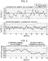
- Fig. 2 is a graph illustrating changes in the basicity of blast furnace slags.
- Fig. 2(a) illustrates changes in the basicity of Comparative Example 1
- Fig. 2(b) illustrates changes in the basicity of Invention Example 1.
- the horizontal axis represents time (day)
- the vertical axis represents total CaO/SiO 2 (-).
- the values of the basicity shown in Fig. 2 are values determined by performing chemical analysis off-line on the components of molten iron and blast furnace slags tapped from the blast furnace.
- Fig. 3 is a graph illustrating changes in the coke ratio.
- the horizontal axis represents time (day), and the vertical axis represents coke ratios (kg/t-pig).
- the coke ratios of 0th day to 19th day are coke ratios of Comparative Example 1, in which blast furnace operation was performed by charging blast furnace feed materials for which no adjustment of the consumptions was made.
- the coke ratios of 20th day to 39th day are coke ratios of Invention Example 1, in which blast furnace operation was performed by charging blast furnace feed materials for which adjustment of a consumption was made at a frequency of once per minute.
- Fig. 4 is a graph illustrating changes in the basicity of blast furnace feed materials and changes in the coke ratio.
- Fig. 4(a) illustrates changes in the basicities of blast furnace feed materials of Comparative Example 2 and Invention Example 2.
- the horizontal axis represents time (hour), and the vertical axis represents total CaO/SiO 2 (-) of blast furnace feed materials.
- Fig. 4(b) illustrates changes in the coke ratios for blast furnace operation of Comparative Example 2 and Invention Example 2.
- the horizontal axis represents time (hour)
- the vertical axis represents coke ratios (kg/t-pig).
- Comparative Example 2 is an operation example in which total CaO and SiO 2 in product sintered ore were measured at a frequency of once every two hours by using X-ray fluorescence, and, by using the measurement results, the consumption of an auxiliary material of blast furnace feed materials was adjusted at the same frequency.
- Invention Example 2 is an operation example in which, similarly to Invention Example 1, the component concentrations of total CaO and SiO 2 in product sintered ore were determined at a frequency of once per minute by using the infrared analyzer 28 provided at the production line 30, and, by using the measurement results, the consumption of an auxiliary material of blast furnace feed materials was adjusted at the same frequency.
- Fig. 5 is a graph illustrating measured values of FeO concentrations of Invention Example 3, Invention Example 4, and Comparative Example 3.
- the vertical axis represents measured values (mass%) of the FeO concentration at a specific time.
- Invention Example 3 is an operation example in which the infrared analyzer 28 was provided at the production line 30, the component concentrations of total CaO, SiO 2 , MgO, Al 2 O 3 , and FeO in product sintered ore were measured at a frequency of once per minute, and, by using the measurement results, the consumption of an auxiliary material of blast furnace feed materials was adjusted at a frequency of once per minute.
- Invention Example 4 is an operation example in which the infrared analyzer 28 was provided at a return ore line 32, the component concentrations of total CaO, SiO 2 , MgO, Al 2 O 3 , and FeO in product sintered ore were measured at a frequency of once per minute, and, by using the measurement results, the consumption of an auxiliary material of blast furnace feed materials was adjusted at a frequency of once per minute.
- Comparative Example 3 is an operation example in which the infrared analyzer 28 was provided at a location of a sintering machine 12 where measurement of the surface of a sintered cake was able to be performed, the component concentrations of total CaO, SiO 2 , MgO, Al 2 O 3 , and FeO in the surface of the sintered cake were measured at a frequency of once per minute, and, by using the measurement results, the consumption of an auxiliary material of blast furnace feed materials was adjusted at a frequency of once per minute.
- a FeO concentration determined by measuring product sintered ore was 7.1 mass%
- a FeO concentration determined by measuring return ore produced from the same sintering raw material was 6.9 mass%.
- This result indicates that the result of measurement of the FeO concentration of return ore and the result of measurement of the FeO concentration of product sintered ore, which were performed by using the infrared analyzer, were not significantly different from each other.
- a FeO concentration determined by measuring, by using the infrared analyzer 28, the surface of a sintered cake obtained by sintering the same sintering raw material was 5.6 mass%, which was significantly different from the FeO concentration determined by measuring product sintered ore.
- an infrared analyzer is only capable of measuring component concentrations in the surface irradiated with infrared light. By radiating infrared light onto the surface of product sintered ore or return ore, average components of the entirety can be determined. This is because product sintered ore or return ore either is homogenized to some extent in the process of crushing. On the other hand, in a sintered cake, a significant difference is generated between the component concentrations of an upper layer and those of a lower layer. This is because the component concentrations of a sintering raw material charged into the pallet differ between an upper layer and a lower layer, and, the heat level during sintering differs between an upper layer and a lower layer.
- Fig. 6 is a graph illustrating amounts of reduction in the coke ratio of Invention Example 3, Invention Example 4, and Comparative Example 3.
- the vertical axis represents amounts of reduction in the coke ratio (kg/t-pig).
- the amount of reduction in the coke ratio illustrated in Fig. 6 is an amount of reduction determined using a coke ratio obtained before adjusting the consumptions of the blast furnace feed materials and a coke ratio obtained when, supposedly, the influence of operation variations had diminished and the operation had entered a steady state, after 120 hours elapsed from the time at which the consumptions of the blast furnace feed materials were adjusted in accordance with Invention Example 3, Invention Example 4, or Comparative Example 3.
- Invention Example 3 in which the consumption of an auxiliary material of the blast furnace feed materials was adjusted by using component concentrations of product sintered ore to be charged into the blast furnace as a blast furnace feed material, and in Invention Example 4, in which the consumption of an auxiliary material of the blast furnace feed materials was adjusted by using component concentrations of return ore having component concentrations similar to the component concentrations of product sintered ore, the coke ratio at a point in time after 120 hours elapsed was reduced.
- Comparative Example 3 in which the consumption of an auxiliary material of the blast furnace feed materials was adjusted by using a measured value of a sintered cake, which had component concentrations significantly different from those of product sintered ore to be charged into the blast furnace, the coke ratio at a point in time after 120 hours elapsed, on the contrary, was increased. It is presumed that this was a result attributable to the fact that, in Comparative Example 3, the component concentrations of the blast furnace feed materials to be charged into the blast furnace were not adjusted to target component concentrations.
Landscapes
- Chemical & Material Sciences (AREA)
- Engineering & Computer Science (AREA)
- Manufacturing & Machinery (AREA)
- Organic Chemistry (AREA)
- Metallurgy (AREA)
- Materials Engineering (AREA)
- Geochemistry & Mineralogy (AREA)
- Geology (AREA)
- Life Sciences & Earth Sciences (AREA)
- Mechanical Engineering (AREA)
- General Life Sciences & Earth Sciences (AREA)
- Environmental & Geological Engineering (AREA)
- Manufacture And Refinement Of Metals (AREA)
- Manufacture Of Iron (AREA)
- Investigating Or Analysing Materials By Optical Means (AREA)
Abstract
Description
- The present invention relates to a blast furnace operation method involving adjusting consumptions of blast furnace feed materials, and in particular, to a blast furnace operation method involving measuring component concentrations of sintered ore, which is a blast furnace feed material, and using the component concentrations to adjust consumptions of blast furnace feed materials.
- Currently, in blast furnace ironmaking methods, iron-bearing materials such as sintered ore, lump iron ore and pellets are mainly used as iron sources for blast furnace feed materials. Sintered ore is a type of agglomerated ore and is obtained as follows. Iron ore having particle sizes less than or equal to 10 mm, miscellaneous iron sources, such as various types of dust generated in ironworks, CaO- bearing materials, such as limestone, quick lime, and slags, auxiliary materials serving as a SiO2 source or a MgO source, such as silica stone, serpentinite, dolomite, and nickel refining slags, and a solid fuel (carbonaceous material) serving as a binding material, such as coke breeze and anthracite, are mixed together with the addition of water in a drum mixer to be granulated and then burned.
- In recent years, the concentration of iron present in a sintering raw material, which is a raw material for sintered ore, has been decreasing, and instead, the component concentration of gangue, such as SiO2 and Al2O3, has been increasing. The component concentrations of ores produced have become inconsistent to such an extent that, even in ores of the same type, the component concentrations may vary for each imported shipment.
- Variations in the component concentrations of a sintering raw material lead to variations in the component concentrations of sintered ore, which is a product. In general, the component concentrations of a material that is charged into a blast furnace are consistently managed for the purpose of controlling the quality of slags, for example. If a component concentration increases, another component needs to be added as an auxiliary material to dilute the component concentration. It is, therefore, necessary to quickly detect a change in component concentrations of sintered ore, lump iron ore, and pellets. Lump iron ore and pellets are products themselves, and, therefore, analysis of component concentrations is performed when, for example, products are unloaded. With regard to sintered ore, however, no online analysis of component concentrations is currently performed, and the current situation is that analysis of component concentrations is very seldom performed.
- If, as a result of a change in the component concentrations of sintered ore, the component concentrations of a blast furnace feed material change and significantly deviate from target component concentrations, and, consequently, the appropriate viscosity of slags deteriorates, it is necessary to increase the temperature of the molten iron to maintain the viscosity of slags. Deterioration in the viscosity of slags leads to deterioration in discharging of slags in a lower portion of a blast furnace, which interferes with the flow of gases and degrades gas permeability. As a result, for example, a need for increasing a consumption of coke to supplement the molten iron temperature and gas permeability may arise. Thus, when the component concentrations of a blast furnace feed material significantly deviate from target component concentrations, the operation of the blast furnace becomes unstable, and various countermeasures need to be taken.
- Technologies for ascertaining the quality of sintered ore include the following, for example.
Patent Literature 1 discloses a technology in which the reducibility and the reduction degradation property of product sintered ore are predicted from the sintering raw material filling status, and, a consumption of a sintering raw material, rather than a consumption ratio for blast furnace feed materials, is adjusted to adjust the blast furnace feed materials. -
Patent Literature 2 discloses a technology in which FeO in product sintered ore is measured, and, on the basis of the difference from an aimed target value, the binding material for the sintering raw material, the water content for granulation, and the amount of exhaust air are adjusted. Furthermore,Patent Literature 3 discloses a technology in which, similarly, FeO in product sintered ore is measured, and, on the basis of the difference from an aimed target value, the amount of city gas to be injected into a sintering machine is adjusted. -
Patent Literature 4 discloses a technology in which the components of product sintered ore are estimated on the basis of the components in a surface layer of a sintering raw material, which are determined by a laser-type component analyzer provided on a sintering machine, and, a sintering raw material is formulated in a manner that reflects the estimate. -
- PTL 1: Japanese Unexamined Patent Application Publication No.
10-324929 - PTL 2: Japanese Unexamined Patent Application Publication No.
57-149433 - PTL 3: Japanese Unexamined Patent Application Publication No.
2011-038735 - PTL 4: Japanese Unexamined Patent Application Publication No.
60-262926 - The technologies disclosed in
Patent Literature 1 toPatent Literature 4, however, are technologies in which a particular component concentration of sintered ore is measured and, by using the measured component concentration, the sintering raw material is adjusted or the conditions for producing sintered ore are adjusted. None ofPatent Literature 1 toPatent Literature 4 discloses adjusting, by using a measured component concentration of sintered ore, the consumptions of blast furnace feed materials to be charged into a blast furnace. Since the component concentrations of sintered ore can also change with the heat level during the sintering reaction, inhibiting changes in the component concentrations of a sintering raw material does not necessarily inhibit changes in the component concentrations of sintered ore. Thus, there has been a problem in that the component concentrations of blast furnace feed materials to be charged into a blast furnace cannot be controlled to target component concentrations. The present invention was made in view of such problems of the related art, and an object of the present invention is to provide a blast furnace operation method that makes it possible to control the component concentrations of blast furnace feed materials to target component concentrations even if there is a change in the component concentrations of a sintering raw material. - Features of the present invention that solve such problems include the following.
- (1) A blast furnace operation method including charging blast furnace feed materials into a blast furnace, the blast furnace feed materials including product sintered ore, lump iron ore, and an auxiliary material, the blast furnace operation method including: a sintering step for sintering a sintering raw material to form a sintered cake; a crushing step for crushing the sintered cake to form sintered ore; a cooling step for cooling the sintered ore; a sieving step for sieving the cooled sintered ore to separate into product sintered ore and return ore; a measuring step for measuring a component concentration of at least one of the cooled sintered ore, the product sintered ore, and the return ore; and an adjusting step for adjusting consumptions of the product sintered ore, the lump iron ore, and the auxiliary material, which are to be included in the blast furnace feed materials, wherein, in the adjusting step, the consumptions of the blast furnace feed materials are adjusted by using the component concentration measured in the measuring step.
- (2) The blast furnace operation method according to (1), wherein the blast furnace feed materials further include pellets, and, in the adjusting step, consumptions of the product sintered ore, the pellets, the lump iron ore, and the auxiliary material, which are to be included in the blast furnace feed materials, are adjusted.
- (3) The blast furnace operation method according to (1) or (2), wherein in the measuring step, the component concentration of at least one of the cooled sintered ore, the product sintered ore, and the return ore is sequentially measured, the cooled sintered ore, the product sintered ore, and the return ore each being transferred on a conveyor.
- (4) The blast furnace operation method according to any one of (1) to (3), wherein, in the measuring step, the component concentration of at least one of the product sintered ore and the return ore is measured.
- (5) The blast furnace operation method according to any one of (1) to (3), wherein, in the measuring step, the component concentration of the product sintered ore is measured.
- (6) The blast furnace operation method according to any one of (1) to (5), wherein, in the measuring step, a component concentration of at least one of total CaO, SiO2, MgO, Al2O3, and FeO is measured.
- By implementing the blast furnace operation method of the present invention, the component concentrations of blast furnace feed materials can be controlled to target component concentrations. Consequently, changes in the viscosity of blast furnace slags, for example, are inhibited, which contributes to stable operation of a blast furnace.
-
-
Fig. 1 is a schematic diagram illustrating an example of a sinteredore production apparatus 10, which can implement a blast furnace operation method according to the present embodiment. -
Fig. 2 is a graph illustrating changes in the basicity of blast furnace slags. -
Fig. 3 is a graph illustrating changes in the coke ratio. -
Fig. 4 is a graph illustrating changes in the basicity of blast furnace feed materials and changes in the coke ratio. -
Fig. 5 is a graph illustrating measured values of FeO concentrations of Invention Example 3, Invention Example 4, and Comparative Example 3. -
Fig. 6 is a graph illustrating amounts of reduction in the coke ratio of Invention Example 3, Invention Example 4, and Comparative Example 3. - In the present invention, a measuring step for measuring component concentrations of sintered ore is provided, and component concentrations of sintered ore are measured in the measuring step. By using the component concentrations measured, the consumptions of product sintered ore, pellets, lump iron ore, and an auxiliary material, which are blast furnace feed materials, are adjusted. Consequently, the component concentrations of blast furnace feed materials can be controlled to reach target component concentrations, and as a result, stable blast furnace operation is made possible. With this finding, the present invention was made. The present invention will now be described with reference to an embodiment of the present invention.
-
Fig. 1 is a schematic diagram illustrating an example of a sinteredore production apparatus 10, which can implement a blast furnace operation method according to the present embodiment. A sinteredore production apparatus 10 includes asintering machine 12, aprimary crusher 14, acooler 16, asecondary crusher 18, a plurality ofsieving devices infrared analyzer 28, aproduct line 30, and areturn ore line 32. - The
sintering machine 12 performs a sintering step. Thesintering machine 12 is, for example, a downward-suction-type Dwight-Lloyd sintering machine. Thesintering machine 12 includes a sintering raw material feeding device, an endless-moving-type pallet, an ignition furnace, and wind boxes. A sintering raw material is charged into the pallet through the sintering raw material feeding device, thereby forming a burden layer of the sintering raw material. The ignition furnace ignites the burden layer. Air within the burden layer is sucked downwardly through the wind boxes, thereby moving the combustion and melting zone within the burden layer toward a lower portion in the burden layer. In this manner, the burden layer is sintered to form a sintered cake. When air within the burden layer is sucked downwardly through the wind boxes, a gas fuel and/or oxygen-gas-enriched air may be supplied from above the burden layer. The gas fuel is a combustible gas selected from the following: blast furnace gas, coke oven gas, a mixed gas of a blast furnace gas and coke oven gas, converter gas, city gas, natural gas, methane gas, ethane gas, propane gas, and a mixed gas thereof. - The
primary crusher 14 performs a crushing step. A sintered cake is crushed by theprimary crusher 14 to form sintered ore. The cooler 16 performs a cooling step. Sintered ore is cooled by the cooler 16 to form cooled sintered ore. - The
sieving devices sieving device 20, cooled sintered ore is sieved and separated into sintered ore having particle sizes greater than 75 mm and sintered ore having particle sizes less than or equal to 75 mm. In the present embodiment, "particle sizes" refers to particle sizes determined by performing sieving with a sieve: for example, "sintered ore having particle sizes greater than 75 mm" refers to particle sizes such that sintered ore, when sieved with a sieve having an opening size of 75 mm, is retained on the sieve, and "sintered ore having particle sizes less than or equal to 75 mm" refers to particle sizes such that sintered ore, when sieved with a sieve having an opening size of 75 mm, is not retained on the sieve. - Sintered ore having particle sizes greater than 75 mm, which is retained on the sieve when sieved with the sieving
device 20, is crushed with thesecondary crusher 18 to reduce the particle sizes to less than or equal to 50 mm. The crushed sintered ore is mixed with non-retained sintered ore, and the mixture is sieved with the sievingdevice 22. This ensures that the upper limit of the particle sizes of product sintered ore is not greater than 75 mm. - Sintered ore having particle sizes less than or equal to 75 mm, which is not retained on the sieve when sieved with the sieving
device 20, is subsequently sieved and separated, by using thesieving devices sieving devices blast furnace 34 by a conveyor belt that forms theproduct line 30. On the other hand, return ore, which is sieved and separated with thesieving devices machine 12 again by a conveyor belt that forms thereturn ore line 32. The value of the particle sizes of sintered ore that is sieved and separated using thesieving devices - The conveyor belt that forms the
product line 30 is provided with theinfrared analyzer 28. Theinfrared analyzer 28 performs the measuring step. In the measuring step, the component concentration of at least one of total CaO, SiO2, MgO, Al2O3, and FeO that are present in product sintered ore are measured. Theinfrared analyzer 28 radiates infrared light having wavelengths ranging from 0.5 µm to 50.0 µm onto sintered ore and receives reflected light from the sintered ore. Total CaO, SiO2, MgO, Al2O3, and FeO that are present in sintered ore each have molecular vibrations and each absorb a specific-wavelength component of the radiated infrared light, and therefore each of the components imparts a specific-wavelength component to reflected infrared light. Accordingly, the component concentrations of total CaO, SiO2, MgO, Al2O3, and FeO in product sintered ore can be measured by analyzing the radiated light and the reflected light. Total CaO is determined by calculating Ca in all compounds including Ca and O, such as CaO, CaCO3, Ca(OH)2, and Fe2CaO4, as CaO. - For example, the
infrared analyzer 28 radiates infrared light having 20 or more wavelengths and receives reflected light reflected from sintered ore, at a frequency of 128 times per minute. By radiating infrared light in a short time as described above, theinfrared analyzer 28 can measure, on-line and sequentially, the component concentrations of sintered ore, which is transferred on the conveyor belt that forms theproduct line 30. Theinfrared analyzer 28 is an example of a component analysis instrument. The component analysis instrument is not limited to an instrument of the type that spectrally analyzes reflected light and may be an instrument of the type that spectrally analyzes transmitted light. In place of theinfrared analyzer 28, it is possible to use a laser analyzer that radiates laser beams onto an object to be measured, a neutron analyzer that radiates neutrons onto an object to be measured, or a microwave analyzer that radiates microwaves onto an object to be measured. - After the component concentrations of product sintered ore is measured, the product sintered ore is transferred to the
blast furnace 34, and is subjected to an adjusting step in which the consumptions of blast furnace feed materials including product sintered ore, pellets, lump iron ore, and an auxiliary material are adjusted. The blast furnace feed materials may include one or more other materials in addition to the materials mentioned above or may not include pellets. In the adjusting step, the total component amounts of the blast furnace feed materials are calculated by using the component concentrations of the product sintered ore measured using theinfrared analyzer 28 and premeasured component concentrations of pellets, lump iron ore, and an auxiliary material, and, by using the calculated value, feed-forward control is performed on the consumptions of the blast furnace feed materials to obtain target component concentrations. For example, the basicity (CaO/SiO2) of the blast furnace feed materials can be controlled to target component concentrations by adjusting the consumption of an auxiliary material to be included in the blast furnace feed materials. - If the FeO concentration of product sintered ore is high, and, consequently, the FeO concentration of blast furnace feed materials is high, the reducibility of the blast furnace feed materials deteriorates. When the reducibility of blast furnace feed materials deteriorates, indirect reduction, which is an exothermic reaction, decreases, and direct reduction, which is an endothermic reaction, increases, and as a result, the heat within the blast furnace becomes insufficient. To resolve the heat insufficiency, an additional amount of reducing agent has to be charged into the blast furnace, which results in an increase in the coke ratio for blast furnace operation. Accordingly, by controlling the FeO concentration of blast furnace feed materials to a target component concentration, an increase in the coke ratio for blast furnace operation can be inhibited, which contributes to stable blast furnace operation. For example, FeO in blast furnace feed materials can be controlled to a target component concentration by adjusting the consumption of lump ore to be included in the blast furnace feed materials.
- As described above, the consumptions of blast furnace feed materials are adjusted to ensure that the component concentrations of the blast furnace feed materials correspond to target component concentrations. In the present embodiment, the frequency at which component concentrations are measured using the
infrared analyzer 28 is 128 times per minute, and the average of the 128 component concentrations was calculated once per minute, and, by using the calculated average of the component concentrations, the consumptions of the blast furnace feed materials were adjusted every minute. - As described above, in the blast furnace operation method according to the present embodiment, component concentrations of product sintered ore, which is transferred on the
product line 30, are measured using theinfrared analyzer 28, and, by using the measured component concentrations, the consumptions of the blast furnace feed materials are adjusted to ensure that target component concentrations are obtained. As a result, even if the component concentrations of a sintering raw material change and consequently the component concentrations of product sintered ore change, the component concentrations of blast furnace feed materials can be controlled to target component concentrations. Charging such blast furnace feed materials into a blast furnace results in stable blast furnace operation and inhibits an increase in the coke ratio for blast furnace operation. - In the example described in the present embodiment, the
infrared analyzer 28 is provided at the conveyor belt that forms theproduct line 30, and, component concentrations of product sintered ore are measured. However, this example is non-limiting. Theinfrared analyzer 28 may be provided at any of one or more locations of the sinteredore production apparatus 10, and component concentrations of at least one or more of cooled sintered ore, product sintered ore, and return ore may be measured. - In a burden layer, which is formed of a sintering raw material charged into a pallet, the component concentrations significantly differ between a surface layer and a lower layer, and, the component concentrations change with the water content of a sintering raw material and/or the condition of a sintering raw material feeding device. Because of its nature, analysis using infrared light is only capable of analyzing a surface layer of an object to be analyzed. Thus, even when the burden layer, in which the component concentrations differ between a surface layer and a lower layer and so the component concentrations change, is measured with the
infrared analyzer 28, the component concentrations of the entire burden layer cannot be measured with high precision. In contrast, after the cooling step, with the sintering raw material having been sintered, crushed, cooled, and homogenized to some extent, the component concentrations of a surface layer and the component concentrations of a lower layer are not significantly different from each other. For this reason, in the measuring step of the present embodiment, component concentrations of at least one of post-cooling-step sintered ore, product sintered ore, and return ore are measured. As a result, even with aninfrared analyzer 28 that is only capable of analyzing a surface layer of an object to be analyzed, component concentrations can be measured with high precision. - When the particle size distribution of sintered ore is broad, infrared light can be radiated only onto a portion of the sintered ore because, for example, infrared light cannot be radiated onto sintered ore having small particle sizes that is hidden behind sintered ore having large particle sizes, and furthermore, reflected light from sintered ore is unstable. In contrast, after the sieving step, with the sintered ore having been sieved and separated into product sintered ore having particle sizes greater than 5 mm and return ore having particle sizes less than or equal to 5 mm, the particle size distribution of sintered ore is narrow. For this reason, it is preferable that component concentrations of at least one of product sintered ore and return ore, which are post-sieving-step ores, be measured in the measuring step. Accordingly, the
infrared analyzer 28 can radiate infrared light onto sintered ore uniformly, and reflected light from sintered ore is stable. As a result, component concentrations can be measured with higher precision. - Thus, after the sieving step, component concentrations of product sintered ore or return ore may be measured in the measuring step, but it is more preferable to measure product sintered ore rather than return ore because component concentrations of product sintered ore, which is used as one of the blast furnace feed materials, can be directly measured.
- The component concentrations of total CaO, SiO2, MgO, Al2O3, and FeO that are present in product sintered ore were measured at a frequency of once per minute by using a sintered
ore production apparatus 10, in which aninfrared analyzer 28 was provided at aproduct line 30. Invention Example 1 is an operation example in which the consumption of an auxiliary material of blast furnace feed materials was adjusted at a frequency of once per minute by using the measurement results. Comparative Example 1 is an operation example in which the consumption of an auxiliary material of blast furnace feed materials was not adjusted. The blast furnace coke ratio and changes in the basicity of blast furnace slags in Comparative Example 1 and Invention Example 1 were measured. -
Fig. 2 is a graph illustrating changes in the basicity of blast furnace slags.Fig. 2(a) illustrates changes in the basicity of Comparative Example 1, andFig. 2(b) illustrates changes in the basicity of Invention Example 1. InFig. 2 , the horizontal axis represents time (day), and the vertical axis represents total CaO/SiO2 (-). The values of the basicity shown inFig. 2 are values determined by performing chemical analysis off-line on the components of molten iron and blast furnace slags tapped from the blast furnace. - In Comparative Example 1, the basicity significantly varied around the target value, as illustrated in
Fig. 2 . In contrast, in Invention Example 1, deviations of the basicity from the target value were small because component concentrations of product sintered ore were measured at a frequency of once per minute, and, by using the component concentrations, the consumption of blast furnace feed materials was adjusted to ensure that the component concentrations of the blast furnace feed materials would correspond to target component concentrations. Thus, it was verified that, by implementing the blast furnace operation method according to the present embodiment, deviations of the basicity of blast furnace slags from a target value can be reduced. -
Fig. 3 is a graph illustrating changes in the coke ratio. InFig. 3 , the horizontal axis represents time (day), and the vertical axis represents coke ratios (kg/t-pig). The coke ratios of 0th day to 19th day are coke ratios of Comparative Example 1, in which blast furnace operation was performed by charging blast furnace feed materials for which no adjustment of the consumptions was made. The coke ratios of 20th day to 39th day are coke ratios of Invention Example 1, in which blast furnace operation was performed by charging blast furnace feed materials for which adjustment of a consumption was made at a frequency of once per minute. - As illustrated in
Fig. 3 , the coke ratio in blast furnace operation was lower in Invention Example 1 than in Comparative Example 1. Thus, it was verified that, by implementing the blast furnace operation method according to the present embodiment, blast furnace operation can be stabilized, and as a result, the coke ratio for blast furnace operation can be inhibited from increasing. -
Fig. 4 is a graph illustrating changes in the basicity of blast furnace feed materials and changes in the coke ratio.Fig. 4(a) illustrates changes in the basicities of blast furnace feed materials of Comparative Example 2 and Invention Example 2. InFig. 4(a) , the horizontal axis represents time (hour), and the vertical axis represents total CaO/SiO2 (-) of blast furnace feed materials.Fig. 4(b) illustrates changes in the coke ratios for blast furnace operation of Comparative Example 2 and Invention Example 2. InFig. 4(b) , the horizontal axis represents time (hour), and the vertical axis represents coke ratios (kg/t-pig). - In
Fig. 4 , Comparative Example 2 is an operation example in which total CaO and SiO2 in product sintered ore were measured at a frequency of once every two hours by using X-ray fluorescence, and, by using the measurement results, the consumption of an auxiliary material of blast furnace feed materials was adjusted at the same frequency. Invention Example 2 is an operation example in which, similarly to Invention Example 1, the component concentrations of total CaO and SiO2 in product sintered ore were determined at a frequency of once per minute by using theinfrared analyzer 28 provided at theproduction line 30, and, by using the measurement results, the consumption of an auxiliary material of blast furnace feed materials was adjusted at the same frequency. - In the examples illustrated in
Fig. 4 , blast furnace operation was performed under the conditions of Comparative Example 2 from 0th hour to 6th hour, and blast furnace operation was performed under the conditions of Invention Example 2 from 6th hour to 19th hour. As illustrated inFig. 4(a) , in Comparative Example 2, too, the consumption of an auxiliary material was adjusted at a frequency of once every two hours, and therefore, changes in the basicity of the blast furnace feed materials appeared to be inhibited in a measurement performed once every two hours. However, when Comparative Example 2 was replaced with Invention Example 2 and the consumption of an auxiliary material of blast furnace feed materials was adjusted at a frequency of once per minute, the coke ratio for blast furnace operation, as illustrated inFig. 4(b) , began to decrease at or around the time at which, presumably, blast furnace feed materials in which the consumption was adjusted was charged into the blast furnace. In general, sintered ore discharged from a sintering machine is cooled with a cooler and subjected to sizing and is thereafter charged, by way of an ore bin of a blast furnace, into the blast furnace. Although depending on the size of an ore bin, the residence time for materials in the ore bin used in this example was approximately eight hours, and therefore it can be considered that the effect began to gradually show in the blast furnace after eight hours. - Thus, in the measurement performed once every two hours, changes in the basicity appeared to be inhibited, but presumably, the basicity of the blast furnace feed materials changed in the intermediate periods, and under this influence, the coke ratio of Comparative Example 2 increased. In contrast, in Invention Example 2, the
infrared analyzer 28 was provided at theproduct line 30, the measurement of total CaO and SiO2 in product sintered ore was performed at a frequency of once per minute, and, by using the measurement results, the consumption of an auxiliary material was adjusted to ensure that the basicity of the blast furnace feed materials would correspond to a target value, and therefore, presumably, changes in the basicity of the blast furnace feed materials were inhibited even in the intermediate period within two hours, and as a result, the coke ratio for blast furnace operation was inhibited from increasing. -
Fig. 5 is a graph illustrating measured values of FeO concentrations of Invention Example 3, Invention Example 4, and Comparative Example 3. InFig. 5 , the vertical axis represents measured values (mass%) of the FeO concentration at a specific time. - Invention Example 3 is an operation example in which the
infrared analyzer 28 was provided at theproduction line 30, the component concentrations of total CaO, SiO2, MgO, Al2O3, and FeO in product sintered ore were measured at a frequency of once per minute, and, by using the measurement results, the consumption of an auxiliary material of blast furnace feed materials was adjusted at a frequency of once per minute. Invention Example 4 is an operation example in which theinfrared analyzer 28 was provided at areturn ore line 32, the component concentrations of total CaO, SiO2, MgO, Al2O3, and FeO in product sintered ore were measured at a frequency of once per minute, and, by using the measurement results, the consumption of an auxiliary material of blast furnace feed materials was adjusted at a frequency of once per minute. Comparative Example 3 is an operation example in which theinfrared analyzer 28 was provided at a location of asintering machine 12 where measurement of the surface of a sintered cake was able to be performed, the component concentrations of total CaO, SiO2, MgO, Al2O3, and FeO in the surface of the sintered cake were measured at a frequency of once per minute, and, by using the measurement results, the consumption of an auxiliary material of blast furnace feed materials was adjusted at a frequency of once per minute. - As illustrated in
Fig. 5 , a FeO concentration determined by measuring product sintered ore was 7.1 mass%, whereas a FeO concentration determined by measuring return ore produced from the same sintering raw material was 6.9 mass%. This result indicates that the result of measurement of the FeO concentration of return ore and the result of measurement of the FeO concentration of product sintered ore, which were performed by using the infrared analyzer, were not significantly different from each other. In contrast, a FeO concentration determined by measuring, by using theinfrared analyzer 28, the surface of a sintered cake obtained by sintering the same sintering raw material was 5.6 mass%, which was significantly different from the FeO concentration determined by measuring product sintered ore. - Because of its nature, an infrared analyzer is only capable of measuring component concentrations in the surface irradiated with infrared light. By radiating infrared light onto the surface of product sintered ore or return ore, average components of the entirety can be determined. This is because product sintered ore or return ore either is homogenized to some extent in the process of crushing. On the other hand, in a sintered cake, a significant difference is generated between the component concentrations of an upper layer and those of a lower layer. This is because the component concentrations of a sintering raw material charged into the pallet differ between an upper layer and a lower layer, and, the heat level during sintering differs between an upper layer and a lower layer. It is presumed that, for the above reasons, the component concentrations of Comparative Example 3, in which the surface of a sintered cake was measured with the infrared analyzer, were significantly different from the component concentrations of Invention Example 3, in which the surface of product sintered ore was measured, as illustrated in
Fig. 5 . -
Fig. 6 is a graph illustrating amounts of reduction in the coke ratio of Invention Example 3, Invention Example 4, and Comparative Example 3. InFig. 6 , the vertical axis represents amounts of reduction in the coke ratio (kg/t-pig). The amount of reduction in the coke ratio illustrated inFig. 6 is an amount of reduction determined using a coke ratio obtained before adjusting the consumptions of the blast furnace feed materials and a coke ratio obtained when, supposedly, the influence of operation variations had diminished and the operation had entered a steady state, after 120 hours elapsed from the time at which the consumptions of the blast furnace feed materials were adjusted in accordance with Invention Example 3, Invention Example 4, or Comparative Example 3. - In Invention Example 3, in which the consumption of an auxiliary material of the blast furnace feed materials was adjusted by using component concentrations of product sintered ore to be charged into the blast furnace as a blast furnace feed material, and in Invention Example 4, in which the consumption of an auxiliary material of the blast furnace feed materials was adjusted by using component concentrations of return ore having component concentrations similar to the component concentrations of product sintered ore, the coke ratio at a point in time after 120 hours elapsed was reduced. On the other hand, in Comparative Example 3, in which the consumption of an auxiliary material of the blast furnace feed materials was adjusted by using a measured value of a sintered cake, which had component concentrations significantly different from those of product sintered ore to be charged into the blast furnace, the coke ratio at a point in time after 120 hours elapsed, on the contrary, was increased. It is presumed that this was a result attributable to the fact that, in Comparative Example 3, the component concentrations of the blast furnace feed materials to be charged into the blast furnace were not adjusted to target component concentrations.
-
- 10
- Sintered ore production apparatus
- 12
- Sintering machine
- 14
- Primary crusher
- 16
- Cooler
- 18
- Secondary crusher
- 20
- Sieving device
- 22
- Sieving device
- 24
- Sieving device
- 26
- Sieving device
- 28
- Infrared analyzer
- 30
- Product line
- 32
- Return ore line
- 34
- Blast furnace
Claims (6)
- A blast furnace operation method including charging blast furnace feed materials into a blast furnace, the blast furnace feed materials including product sintered ore, lump iron ore, and an auxiliary material, the blast furnace operation method comprising:a sintering step for sintering a sintering raw material to form a sintered cake;a crushing step for crushing the sintered cake to form sintered ore;a cooling step for cooling the sintered ore;a sieving step for sieving the cooled sintered ore to separate into product sintered ore and return ore;a measuring step for measuring a component concentration of at least one of the cooled sintered ore, the product sintered ore, and the return ore; andan adjusting step for adjusting consumptions of the product sintered ore, the lump iron ore, and the auxiliary material, which are to be included in the blast furnace feed materials,wherein, in the adjusting step, the consumptions of the blast furnace feed materials are adjusted by using the component concentration measured in the measuring step.
- The blast furnace operation method according to Claim 1, wherein,
the blast furnace feed materials further include pellets, and
in the adjusting step, consumptions of the product sintered ore, the pellets, the lump iron ore, and the auxiliary material, which are to be included in the blast furnace feed materials, are adjusted. - The blast furnace operation method according to Claim 1 or 2, wherein, in the measuring step, the component concentration of at least one of the cooled sintered ore, the product sintered ore, and the return ore is sequentially measured, the cooled sintered ore, the product sintered ore, and the return ore each being transferred on a conveyor.
- The blast furnace operation method according to any one of Claims 1 to 3, wherein, in the measuring step, the component concentration of at least one of the product sintered ore and the return ore is measured.
- The blast furnace operation method according to any one of Claims 1 to 3, wherein, in the measuring step, the component concentration of the product sintered ore is measured.
- The blast furnace operation method according to any one of Claims 1 to 5, wherein, in the measuring step, a component concentration of at least one of total CaO, SiO2, MgO, Al2O3, and FeO is measured.
Applications Claiming Priority (2)
| Application Number | Priority Date | Filing Date | Title |
|---|---|---|---|
| JP2016243989 | 2016-12-16 | ||
| PCT/JP2017/044474 WO2018110521A1 (en) | 2016-12-16 | 2017-12-12 | Method for operating blast furnace |
Publications (3)
| Publication Number | Publication Date |
|---|---|
| EP3517632A1 true EP3517632A1 (en) | 2019-07-31 |
| EP3517632A4 EP3517632A4 (en) | 2019-11-06 |
| EP3517632B1 EP3517632B1 (en) | 2021-11-24 |
Family
ID=62558564
Family Applications (1)
| Application Number | Title | Priority Date | Filing Date |
|---|---|---|---|
| EP17879791.6A Active EP3517632B1 (en) | 2016-12-16 | 2017-12-12 | Blast furnace operation method |
Country Status (7)
| Country | Link |
|---|---|
| EP (1) | EP3517632B1 (en) |
| JP (1) | JP6519036B2 (en) |
| KR (1) | KR102303009B1 (en) |
| CN (1) | CN110073006A (en) |
| PH (1) | PH12019501367A1 (en) |
| TW (1) | TWI658147B (en) |
| WO (1) | WO2018110521A1 (en) |
Families Citing this family (2)
| Publication number | Priority date | Publication date | Assignee | Title |
|---|---|---|---|---|
| CN112522460B (en) * | 2020-11-18 | 2022-05-17 | 山东钢铁集团日照有限公司 | Method for adjusting airflow distribution by spreading blast furnace burden |
| CN116297349A (en) * | 2022-01-25 | 2023-06-23 | 虔东稀土集团股份有限公司 | Rare earth metal production on-line measuring system |
Family Cites Families (22)
| Publication number | Priority date | Publication date | Assignee | Title |
|---|---|---|---|---|
| JPS5910966B2 (en) * | 1979-09-28 | 1984-03-13 | 住友金属工業株式会社 | How to operate a blast furnace |
| JPS5751206A (en) * | 1980-09-12 | 1982-03-26 | Sumitomo Metal Ind Ltd | Operating method for blast furnace |
| JPS57149433A (en) | 1981-03-07 | 1982-09-16 | Nisshin Steel Co Ltd | Method and device for preparing sintered ore having preset content of feo |
| JPS60262926A (en) * | 1984-06-08 | 1985-12-26 | Kawasaki Steel Corp | Method for controlling concentration of component in product sintered ore |
| JPH06108124A (en) * | 1992-09-29 | 1994-04-19 | Nippon Steel Corp | Operation of blast furnace |
| JPH10324929A (en) | 1997-05-26 | 1998-12-08 | Nippon Steel Corp | Production of sintered ore |
| JP3787237B2 (en) * | 1998-01-23 | 2006-06-21 | 新日本製鐵株式会社 | Method of charging high-pellet iron ore into a blast furnace |
| KR100374231B1 (en) * | 1998-07-31 | 2003-05-16 | 주식회사 포스코 | Manufacturing method of sintered light using recycled buoyancy |
| JP2001107115A (en) * | 1999-10-06 | 2001-04-17 | Nippon Steel Corp | Operation of blast funace using highly reducible sintered ore |
| KR100786499B1 (en) * | 2001-12-18 | 2007-12-17 | 주식회사 포스코 | Method for manufacturing the sintering ore |
| RU2240351C2 (en) * | 2002-04-22 | 2004-11-20 | Открытое акционерное общество "Новолипецкий металлургический комбинат" (ОАО "НЛМК") | Blast smelting method |
| JP2005097658A (en) * | 2003-09-24 | 2005-04-14 | Jfe Steel Kk | Method for predicting main raw material component ratio of sintered ore and method for controlling component ratio of sintered ore and program for predicting main raw material component ratio of sintered ore |
| JP2005298923A (en) * | 2004-04-13 | 2005-10-27 | Nippon Steel Corp | High ore/reducing material ratio operation method in blast furnace |
| JP4802739B2 (en) * | 2006-01-31 | 2011-10-26 | Jfeスチール株式会社 | Blast furnace raw material mixing degree measuring method and blast furnace raw material mixing degree measuring device |
| JP5012138B2 (en) * | 2007-03-28 | 2012-08-29 | 住友金属工業株式会社 | Blast furnace operation method |
| JP5544784B2 (en) * | 2009-08-17 | 2014-07-09 | Jfeスチール株式会社 | Sintering machine |
| CN102719580B (en) * | 2011-03-29 | 2014-11-05 | 鞍钢股份有限公司 | Blast furnace operation method for improving hearth coke strength |
| JP2013147718A (en) * | 2012-01-20 | 2013-08-01 | Nippon Steel & Sumitomo Metal Corp | Method for producing sintered ore |
| CN102722652B (en) * | 2012-06-01 | 2015-09-16 | 攀钢集团攀枝花钢钒有限公司 | A kind of blast furnace process pricing and optimization method |
| CN104164558B (en) * | 2014-08-27 | 2016-04-13 | 攀钢集团成都钢钒有限公司 | A kind of sintering circuit sinter quality control method |
| JP2016130341A (en) * | 2015-01-14 | 2016-07-21 | 株式会社神戸製鋼所 | Method of producing sintered ore raw material using magnetite ore |
| CN104593532B (en) * | 2015-01-19 | 2017-07-07 | 河北联合大学 | A kind of ironmaking system furnace charge optimization method |
-
2017
- 2017-12-12 JP JP2018556672A patent/JP6519036B2/en active Active
- 2017-12-12 WO PCT/JP2017/044474 patent/WO2018110521A1/en unknown
- 2017-12-12 EP EP17879791.6A patent/EP3517632B1/en active Active
- 2017-12-12 KR KR1020197017127A patent/KR102303009B1/en active IP Right Grant
- 2017-12-12 CN CN201780077773.1A patent/CN110073006A/en active Pending
- 2017-12-14 TW TW106143969A patent/TWI658147B/en active
-
2019
- 2019-06-14 PH PH12019501367A patent/PH12019501367A1/en unknown
Also Published As
| Publication number | Publication date |
|---|---|
| TW201829792A (en) | 2018-08-16 |
| TWI658147B (en) | 2019-05-01 |
| JP6519036B2 (en) | 2019-05-29 |
| EP3517632B1 (en) | 2021-11-24 |
| KR20190085970A (en) | 2019-07-19 |
| JPWO2018110521A1 (en) | 2019-03-28 |
| CN110073006A (en) | 2019-07-30 |
| WO2018110521A1 (en) | 2018-06-21 |
| PH12019501367A1 (en) | 2020-02-24 |
| EP3517632A4 (en) | 2019-11-06 |
| KR102303009B1 (en) | 2021-09-15 |
Similar Documents
| Publication | Publication Date | Title |
|---|---|---|
| EP3517632B1 (en) | Blast furnace operation method | |
| EP3550037A1 (en) | Method for manufacturing sintered ore | |
| JP5477170B2 (en) | Method for producing sintered ore | |
| Teguri et al. | Manganese ore pre-reduction using a rotary kiln to manufacture super-low-phosphorus ferromanganese | |
| JP6866856B2 (en) | Sintered ore manufacturing method and blast furnace operation method | |
| JP6489092B2 (en) | Sinter ore manufacturing method and sintered ore manufacturing equipment line | |
| EP3670685B1 (en) | Method for manufacturing sintered ore | |
| JP6043271B2 (en) | Method for producing reduced iron | |
| JP2007277594A (en) | Sintered ore production method | |
| JP6874780B2 (en) | Sintered ore manufacturing method | |
| Borisov et al. | Factory tests of a technology for recycling metallurgical sludge that contains iron and zinc | |
| JP6763412B2 (en) | Sintered ore manufacturing method | |
| JP2024048561A (en) | Sinter manufacturing method | |
| JP2013142167A (en) | Method for producing granular metal iron | |
| JPH1180845A (en) | Production of low silica sintered ore | |
| JP2008169433A (en) | Method for manufacturing sintered ore | |
| KR20130047112A (en) | Prediction method of sintering productivity |
Legal Events
| Date | Code | Title | Description |
|---|---|---|---|
| STAA | Information on the status of an ep patent application or granted ep patent |
Free format text: STATUS: THE INTERNATIONAL PUBLICATION HAS BEEN MADE |
|
| PUAI | Public reference made under article 153(3) epc to a published international application that has entered the european phase |
Free format text: ORIGINAL CODE: 0009012 |
|
| STAA | Information on the status of an ep patent application or granted ep patent |
Free format text: STATUS: REQUEST FOR EXAMINATION WAS MADE |
|
| 17P | Request for examination filed |
Effective date: 20190426 |
|
| AK | Designated contracting states |
Kind code of ref document: A1 Designated state(s): AL AT BE BG CH CY CZ DE DK EE ES FI FR GB GR HR HU IE IS IT LI LT LU LV MC MK MT NL NO PL PT RO RS SE SI SK SM TR |
|
| AX | Request for extension of the european patent |
Extension state: BA ME |
|
| A4 | Supplementary search report drawn up and despatched |
Effective date: 20191004 |
|
| RIC1 | Information provided on ipc code assigned before grant |
Ipc: C21B 5/00 20060101AFI20190927BHEP Ipc: C22B 1/16 20060101ALI20190927BHEP Ipc: C21B 5/04 20060101ALI20190927BHEP |
|
| DAV | Request for validation of the european patent (deleted) | ||
| DAX | Request for extension of the european patent (deleted) | ||
| STAA | Information on the status of an ep patent application or granted ep patent |
Free format text: STATUS: EXAMINATION IS IN PROGRESS |
|
| 17Q | First examination report despatched |
Effective date: 20200707 |
|
| STAA | Information on the status of an ep patent application or granted ep patent |
Free format text: STATUS: EXAMINATION IS IN PROGRESS |
|
| REG | Reference to a national code |
Ref country code: DE Ref legal event code: R079 Ref document number: 602017049974 Country of ref document: DE Free format text: PREVIOUS MAIN CLASS: C21B0005000000 Ipc: C22B0001200000 |
|
| RIC1 | Information provided on ipc code assigned before grant |
Ipc: C22B 1/20 20060101AFI20210430BHEP Ipc: C21B 5/00 20060101ALI20210430BHEP Ipc: C21B 5/04 20060101ALI20210430BHEP Ipc: C22B 1/16 20060101ALI20210430BHEP |
|
| GRAP | Despatch of communication of intention to grant a patent |
Free format text: ORIGINAL CODE: EPIDOSNIGR1 |
|
| STAA | Information on the status of an ep patent application or granted ep patent |
Free format text: STATUS: GRANT OF PATENT IS INTENDED |
|
| RIN1 | Information on inventor provided before grant (corrected) |
Inventor name: IWAMI YUJI Inventor name: NONAKA SHUNSUKE Inventor name: HAYASAKA YASUKAZU |
|
| INTG | Intention to grant announced |
Effective date: 20210614 |
|
| GRAS | Grant fee paid |
Free format text: ORIGINAL CODE: EPIDOSNIGR3 |
|
| GRAA | (expected) grant |
Free format text: ORIGINAL CODE: 0009210 |
|
| STAA | Information on the status of an ep patent application or granted ep patent |
Free format text: STATUS: THE PATENT HAS BEEN GRANTED |
|
| AK | Designated contracting states |
Kind code of ref document: B1 Designated state(s): AL AT BE BG CH CY CZ DE DK EE ES FI FR GB GR HR HU IE IS IT LI LT LU LV MC MK MT NL NO PL PT RO RS SE SI SK SM TR |
|
| REG | Reference to a national code |
Ref country code: GB Ref legal event code: FG4D |
|
| REG | Reference to a national code |
Ref country code: AT Ref legal event code: REF Ref document number: 1449929 Country of ref document: AT Kind code of ref document: T Effective date: 20211215 |
|
| REG | Reference to a national code |
Ref country code: DE Ref legal event code: R096 Ref document number: 602017049974 Country of ref document: DE |
|
| REG | Reference to a national code |
Ref country code: IE Ref legal event code: FG4D |
|
| REG | Reference to a national code |
Ref country code: LT Ref legal event code: MG9D |
|
| REG | Reference to a national code |
Ref country code: NL Ref legal event code: MP Effective date: 20211124 |
|
| REG | Reference to a national code |
Ref country code: AT Ref legal event code: MK05 Ref document number: 1449929 Country of ref document: AT Kind code of ref document: T Effective date: 20211124 |
|
| PG25 | Lapsed in a contracting state [announced via postgrant information from national office to epo] |
Ref country code: RS Free format text: LAPSE BECAUSE OF FAILURE TO SUBMIT A TRANSLATION OF THE DESCRIPTION OR TO PAY THE FEE WITHIN THE PRESCRIBED TIME-LIMIT Effective date: 20211124 Ref country code: LT Free format text: LAPSE BECAUSE OF FAILURE TO SUBMIT A TRANSLATION OF THE DESCRIPTION OR TO PAY THE FEE WITHIN THE PRESCRIBED TIME-LIMIT Effective date: 20211124 Ref country code: FI Free format text: LAPSE BECAUSE OF FAILURE TO SUBMIT A TRANSLATION OF THE DESCRIPTION OR TO PAY THE FEE WITHIN THE PRESCRIBED TIME-LIMIT Effective date: 20211124 Ref country code: BG Free format text: LAPSE BECAUSE OF FAILURE TO SUBMIT A TRANSLATION OF THE DESCRIPTION OR TO PAY THE FEE WITHIN THE PRESCRIBED TIME-LIMIT Effective date: 20220224 Ref country code: AT Free format text: LAPSE BECAUSE OF FAILURE TO SUBMIT A TRANSLATION OF THE DESCRIPTION OR TO PAY THE FEE WITHIN THE PRESCRIBED TIME-LIMIT Effective date: 20211124 |
|
| PG25 | Lapsed in a contracting state [announced via postgrant information from national office to epo] |
Ref country code: IS Free format text: LAPSE BECAUSE OF FAILURE TO SUBMIT A TRANSLATION OF THE DESCRIPTION OR TO PAY THE FEE WITHIN THE PRESCRIBED TIME-LIMIT Effective date: 20220324 Ref country code: SE Free format text: LAPSE BECAUSE OF FAILURE TO SUBMIT A TRANSLATION OF THE DESCRIPTION OR TO PAY THE FEE WITHIN THE PRESCRIBED TIME-LIMIT Effective date: 20211124 Ref country code: PT Free format text: LAPSE BECAUSE OF FAILURE TO SUBMIT A TRANSLATION OF THE DESCRIPTION OR TO PAY THE FEE WITHIN THE PRESCRIBED TIME-LIMIT Effective date: 20220324 Ref country code: PL Free format text: LAPSE BECAUSE OF FAILURE TO SUBMIT A TRANSLATION OF THE DESCRIPTION OR TO PAY THE FEE WITHIN THE PRESCRIBED TIME-LIMIT Effective date: 20211124 Ref country code: NO Free format text: LAPSE BECAUSE OF FAILURE TO SUBMIT A TRANSLATION OF THE DESCRIPTION OR TO PAY THE FEE WITHIN THE PRESCRIBED TIME-LIMIT Effective date: 20220224 Ref country code: NL Free format text: LAPSE BECAUSE OF FAILURE TO SUBMIT A TRANSLATION OF THE DESCRIPTION OR TO PAY THE FEE WITHIN THE PRESCRIBED TIME-LIMIT Effective date: 20211124 Ref country code: LV Free format text: LAPSE BECAUSE OF FAILURE TO SUBMIT A TRANSLATION OF THE DESCRIPTION OR TO PAY THE FEE WITHIN THE PRESCRIBED TIME-LIMIT Effective date: 20211124 Ref country code: HR Free format text: LAPSE BECAUSE OF FAILURE TO SUBMIT A TRANSLATION OF THE DESCRIPTION OR TO PAY THE FEE WITHIN THE PRESCRIBED TIME-LIMIT Effective date: 20211124 Ref country code: GR Free format text: LAPSE BECAUSE OF FAILURE TO SUBMIT A TRANSLATION OF THE DESCRIPTION OR TO PAY THE FEE WITHIN THE PRESCRIBED TIME-LIMIT Effective date: 20220225 Ref country code: ES Free format text: LAPSE BECAUSE OF FAILURE TO SUBMIT A TRANSLATION OF THE DESCRIPTION OR TO PAY THE FEE WITHIN THE PRESCRIBED TIME-LIMIT Effective date: 20211124 |
|
| PG25 | Lapsed in a contracting state [announced via postgrant information from national office to epo] |
Ref country code: SM Free format text: LAPSE BECAUSE OF FAILURE TO SUBMIT A TRANSLATION OF THE DESCRIPTION OR TO PAY THE FEE WITHIN THE PRESCRIBED TIME-LIMIT Effective date: 20211124 Ref country code: SK Free format text: LAPSE BECAUSE OF FAILURE TO SUBMIT A TRANSLATION OF THE DESCRIPTION OR TO PAY THE FEE WITHIN THE PRESCRIBED TIME-LIMIT Effective date: 20211124 Ref country code: RO Free format text: LAPSE BECAUSE OF FAILURE TO SUBMIT A TRANSLATION OF THE DESCRIPTION OR TO PAY THE FEE WITHIN THE PRESCRIBED TIME-LIMIT Effective date: 20211124 Ref country code: EE Free format text: LAPSE BECAUSE OF FAILURE TO SUBMIT A TRANSLATION OF THE DESCRIPTION OR TO PAY THE FEE WITHIN THE PRESCRIBED TIME-LIMIT Effective date: 20211124 Ref country code: DK Free format text: LAPSE BECAUSE OF FAILURE TO SUBMIT A TRANSLATION OF THE DESCRIPTION OR TO PAY THE FEE WITHIN THE PRESCRIBED TIME-LIMIT Effective date: 20211124 Ref country code: CZ Free format text: LAPSE BECAUSE OF FAILURE TO SUBMIT A TRANSLATION OF THE DESCRIPTION OR TO PAY THE FEE WITHIN THE PRESCRIBED TIME-LIMIT Effective date: 20211124 |
|
| REG | Reference to a national code |
Ref country code: CH Ref legal event code: PL |
|
| REG | Reference to a national code |
Ref country code: DE Ref legal event code: R097 Ref document number: 602017049974 Country of ref document: DE |
|
| PG25 | Lapsed in a contracting state [announced via postgrant information from national office to epo] |
Ref country code: MC Free format text: LAPSE BECAUSE OF FAILURE TO SUBMIT A TRANSLATION OF THE DESCRIPTION OR TO PAY THE FEE WITHIN THE PRESCRIBED TIME-LIMIT Effective date: 20211124 |
|
| PLBE | No opposition filed within time limit |
Free format text: ORIGINAL CODE: 0009261 |
|
| STAA | Information on the status of an ep patent application or granted ep patent |
Free format text: STATUS: NO OPPOSITION FILED WITHIN TIME LIMIT |
|
| GBPC | Gb: european patent ceased through non-payment of renewal fee |
Effective date: 20220224 |
|
| PG25 | Lapsed in a contracting state [announced via postgrant information from national office to epo] |
Ref country code: LU Free format text: LAPSE BECAUSE OF NON-PAYMENT OF DUE FEES Effective date: 20211212 Ref country code: IE Free format text: LAPSE BECAUSE OF NON-PAYMENT OF DUE FEES Effective date: 20211212 Ref country code: AL Free format text: LAPSE BECAUSE OF FAILURE TO SUBMIT A TRANSLATION OF THE DESCRIPTION OR TO PAY THE FEE WITHIN THE PRESCRIBED TIME-LIMIT Effective date: 20211124 |
|
| 26N | No opposition filed |
Effective date: 20220825 |
|
| PG25 | Lapsed in a contracting state [announced via postgrant information from national office to epo] |
Ref country code: SI Free format text: LAPSE BECAUSE OF FAILURE TO SUBMIT A TRANSLATION OF THE DESCRIPTION OR TO PAY THE FEE WITHIN THE PRESCRIBED TIME-LIMIT Effective date: 20211124 |
|
| PG25 | Lapsed in a contracting state [announced via postgrant information from national office to epo] |
Ref country code: LI Free format text: LAPSE BECAUSE OF NON-PAYMENT OF DUE FEES Effective date: 20211231 Ref country code: CH Free format text: LAPSE BECAUSE OF NON-PAYMENT OF DUE FEES Effective date: 20211231 |
|
| PG25 | Lapsed in a contracting state [announced via postgrant information from national office to epo] |
Ref country code: GB Free format text: LAPSE BECAUSE OF NON-PAYMENT OF DUE FEES Effective date: 20220224 |
|
| PG25 | Lapsed in a contracting state [announced via postgrant information from national office to epo] |
Ref country code: IT Free format text: LAPSE BECAUSE OF FAILURE TO SUBMIT A TRANSLATION OF THE DESCRIPTION OR TO PAY THE FEE WITHIN THE PRESCRIBED TIME-LIMIT Effective date: 20211124 |
|
| PG25 | Lapsed in a contracting state [announced via postgrant information from national office to epo] |
Ref country code: CY Free format text: LAPSE BECAUSE OF FAILURE TO SUBMIT A TRANSLATION OF THE DESCRIPTION OR TO PAY THE FEE WITHIN THE PRESCRIBED TIME-LIMIT Effective date: 20211124 |
|
| PG25 | Lapsed in a contracting state [announced via postgrant information from national office to epo] |
Ref country code: HU Free format text: LAPSE BECAUSE OF FAILURE TO SUBMIT A TRANSLATION OF THE DESCRIPTION OR TO PAY THE FEE WITHIN THE PRESCRIBED TIME-LIMIT; INVALID AB INITIO Effective date: 20171212 |
|
| PGFP | Annual fee paid to national office [announced via postgrant information from national office to epo] |
Ref country code: FR Payment date: 20231108 Year of fee payment: 7 Ref country code: DE Payment date: 20231031 Year of fee payment: 7 |
|
| PGFP | Annual fee paid to national office [announced via postgrant information from national office to epo] |
Ref country code: BE Payment date: 20231121 Year of fee payment: 7 |
|
| PG25 | Lapsed in a contracting state [announced via postgrant information from national office to epo] |
Ref country code: MK Free format text: LAPSE BECAUSE OF FAILURE TO SUBMIT A TRANSLATION OF THE DESCRIPTION OR TO PAY THE FEE WITHIN THE PRESCRIBED TIME-LIMIT Effective date: 20211124 |