EP3517482A1 - Fahrerkabine für ein flurförderzeug - Google Patents
Fahrerkabine für ein flurförderzeug Download PDFInfo
- Publication number
- EP3517482A1 EP3517482A1 EP19151621.0A EP19151621A EP3517482A1 EP 3517482 A1 EP3517482 A1 EP 3517482A1 EP 19151621 A EP19151621 A EP 19151621A EP 3517482 A1 EP3517482 A1 EP 3517482A1
- Authority
- EP
- European Patent Office
- Prior art keywords
- driver
- pillars
- cab
- profile
- cab according
- Prior art date
- Legal status (The legal status is an assumption and is not a legal conclusion. Google has not performed a legal analysis and makes no representation as to the accuracy of the status listed.)
- Granted
Links
Images


Classifications
-
- B—PERFORMING OPERATIONS; TRANSPORTING
- B66—HOISTING; LIFTING; HAULING
- B66F—HOISTING, LIFTING, HAULING OR PUSHING, NOT OTHERWISE PROVIDED FOR, e.g. DEVICES WHICH APPLY A LIFTING OR PUSHING FORCE DIRECTLY TO THE SURFACE OF A LOAD
- B66F9/00—Devices for lifting or lowering bulky or heavy goods for loading or unloading purposes
- B66F9/06—Devices for lifting or lowering bulky or heavy goods for loading or unloading purposes movable, with their loads, on wheels or the like, e.g. fork-lift trucks
- B66F9/075—Constructional features or details
- B66F9/07545—Overhead guards
-
- B—PERFORMING OPERATIONS; TRANSPORTING
- B62—LAND VEHICLES FOR TRAVELLING OTHERWISE THAN ON RAILS
- B62D—MOTOR VEHICLES; TRAILERS
- B62D33/00—Superstructures for load-carrying vehicles
- B62D33/06—Drivers' cabs
-
- B—PERFORMING OPERATIONS; TRANSPORTING
- B66—HOISTING; LIFTING; HAULING
- B66F—HOISTING, LIFTING, HAULING OR PUSHING, NOT OTHERWISE PROVIDED FOR, e.g. DEVICES WHICH APPLY A LIFTING OR PUSHING FORCE DIRECTLY TO THE SURFACE OF A LOAD
- B66F9/00—Devices for lifting or lowering bulky or heavy goods for loading or unloading purposes
- B66F9/06—Devices for lifting or lowering bulky or heavy goods for loading or unloading purposes movable, with their loads, on wheels or the like, e.g. fork-lift trucks
- B66F9/075—Constructional features or details
- B66F9/07504—Accessories, e.g. for towing, charging, locking
-
- B—PERFORMING OPERATIONS; TRANSPORTING
- B66—HOISTING; LIFTING; HAULING
- B66F—HOISTING, LIFTING, HAULING OR PUSHING, NOT OTHERWISE PROVIDED FOR, e.g. DEVICES WHICH APPLY A LIFTING OR PUSHING FORCE DIRECTLY TO THE SURFACE OF A LOAD
- B66F9/00—Devices for lifting or lowering bulky or heavy goods for loading or unloading purposes
- B66F9/06—Devices for lifting or lowering bulky or heavy goods for loading or unloading purposes movable, with their loads, on wheels or the like, e.g. fork-lift trucks
- B66F9/075—Constructional features or details
- B66F9/07513—Details concerning the chassis
-
- B—PERFORMING OPERATIONS; TRANSPORTING
- B66—HOISTING; LIFTING; HAULING
- B66F—HOISTING, LIFTING, HAULING OR PUSHING, NOT OTHERWISE PROVIDED FOR, e.g. DEVICES WHICH APPLY A LIFTING OR PUSHING FORCE DIRECTLY TO THE SURFACE OF A LOAD
- B66F9/00—Devices for lifting or lowering bulky or heavy goods for loading or unloading purposes
- B66F9/06—Devices for lifting or lowering bulky or heavy goods for loading or unloading purposes movable, with their loads, on wheels or the like, e.g. fork-lift trucks
- B66F9/075—Constructional features or details
- B66F9/0759—Details of operating station, e.g. seats, levers, operator platforms, cabin suspension
Definitions
- the present invention relates to a driver's cab for an industrial truck.
- a driver's cab can be provided with a place for the driver.
- the space may be formed in a driver's cabin, for example, as a seat or as a driver's stand. It is known to equip a corresponding driver's cab with a driver's protection roof.
- the driver's safety roof has the task of providing the best possible view of the lifted load and, on the other hand, of protecting the driver from falling objects.
- the driver's cab with the driver's protection roof must be sufficiently stable for this purpose.
- these pillars may be inclined slightly forward, with the rider roof then being formed as a crown with a corresponding brace.
- Object of the present invention is to provide a cab for an industrial truck, which offers good visibility in the working environment to the outside with the greatest possible stability.
- the driver's cab according to the invention is provided for an industrial truck, in particular for a reach truck, in which an operator is protected by a driver's protection roof.
- a special feature of the driver's cab according to the invention is that the driver's protection roof is supported by four columns, two being designed as A-pillar and two as B-pillar.
- the B-pillars have a load part of the truck and between these an end wall is arranged and that between the A Pillars an entry area is provided.
- the B-pillars are formed as a tubular profile, for example as a round cross-section, oval tube profile or as a round double profile with a waist-like constriction.
- At least one, preferably both A-pillars are formed from a corner profile, which has two legs arranged at an angle to each other.
- the corner profile is designed as an open profile, which has two angularly mutually arranged, each flat leg.
- a corner profile with each other at an angle arranged legs produces a much lower limitation of the field of view.
- the use of four pillars also ensures that the field of vision required for the driver's discretion remains clear.
- the stiffness of the corner profile allows a low material usage, which also leads to a clear field of view.
- the corner profile consumes little space, whereby the interior of the cab can be used well.
- the corner profile is positioned adjacent to a driver's seat or a driver's stand.
- the legs of the corner profile are formed as flat legs, which are connected to each other via a rounded transition region.
- the transition area forms an outer edge of the driver's cab.
- the corner profile for the driver's cab according to the invention consists essentially of a flat material which has a rounded transition region approximately in the center, wherein the legs projecting therefrom extend flat away and preferably at a constant angle to each other in the longitudinal direction of the profile.
- both A-pillars are formed as a corner profile, the A-pillars need not be identical.
- fastening means for fastening the driver's cab to a vehicle frame are provided.
- the driver's cab is a finished welded part, which as a whole is mounted as a preassembled unit on the vehicle frame of the industrial truck.
- fastening means such as eyelets, rings, openings or the like may be provided, via which the driver's cab is mounted and fastened to the vehicle frame.
- the driver's shelter roof is formed with a U-shaped flat profile.
- an upright holding profile is arranged, on each of which the ends are held by running between the legs transverse profiles.
- the holding profiles can be formed by folded edges of the flat profile.
- the cross sections are mounted obliquely relative to the vertical to the stationary holding profiles, so that an obliquely upward view does not fall on the broad side of the crossbars, but only partially or preferably only on its narrow side obstruct the view upwards.
- a panoramic roof made of glass can rest on the U-shaped flat profile.
- a closure profile connects the free legs of the U-shaped profile.
- this peripheral roof frame is connected to the four columns, for which purpose a further peripheral frame profile can surround the roof frame made of U-shaped profile and end profile.
- each of the two side walls on an intermediate plate which is connected at the end with A-pillar and B-pillar.
- the intermediate plate serves as a core for the construction of the side wall, which forms a kind of sandwich structure with the intermediate plate in the center.
- a top cladding panel which is flush with the A pillar is mounted on the side of the intermediate sheet facing the outside of the driver's cab.
- the upper cladding panel is flush with one of the A-pillars and their legs.
- the upper cladding sheet may also be formed integrally with one of the legs of one of the A-pillars.
- the intermediate plate is attached to its attachment to the A-pillar on the inside of the leg of the corner profile, the intermediate plate jumps back, so that the upper cladding sheet can be flush with the A-pillar.
- a lower cladding sheet is attached to form a joint opposite the upper cladding sheet.
- an A-pillar can be equipped with an access panel on one side.
- the entry area is preferably limited by one of the A-pillars and on its opposite side by the mounted on the other A-pillar entry plate.
- entry areas are possible in which entry panels are attached to both sides of the A-pillar.
- the columns are welded to the driver's protection roof and to the intermediate plate of the other side walls.
- the driver's cab forms a total of a welded construction, wherein only the two A-pillars are not directly connected to each other at the end remote from the driver's protection roof by the entry area, but via an entry support.
- the end wall has a holding portion for a driving window.
- the end wall of the driver's cab forms the transition from the drive part to a load section of the truck.
- a range between the driver's cab and load part at least partially covering the driver's protection is provided which prevents a Hereing Shape or other contact with the mast from the driver's cab.
- a visual break can be provided in at least one of the A-pillars. This is preferably provided centrally in the rounded transition region of the A-pillar. If only one A pillar is designed as a corner profile, then this is preferably formed adjacent to a driving area, in particular a driver's seat or a driver's platform.
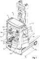
- Fig. 1 shows a truck 10, which is designed as a reach truck.
- the truck has a push tower 12 which is adjustable along the wheel arms 14.
- a driver's cab 16 has a driver's shelter roof (in Fig. 1 only incompletely shown) supported by four columns 18a, 18b, 20a, 20b. Relative to the mast 12, the columns 20a, 20b are referred to as B-pillars.
- the B-pillars 20a, 20b consist of a tubular profile having a round cross-section.
- the entry area 20 limiting columns 18a, 18b are hereinafter referred to as A-pillars.
- the distinction in A-pillars and B-pillars is arbitrarily determined for the truck 10, without reference to a direction of travel, since the vehicle during its regular use in both directions R and R 'moves.
- the two A-pillars are formed as corner profiles, the flat legs 19b and 19'b have.
- Both legs 19b and 19'b are at least at a right angle, preferably at an angle of 100 ° to 130 ° to each other.
- both A-pillars are designed as corner profiles, if only one corner profile is provided, then the driver-near A-pillar is preferably formed as a corner profile.
- a driver's seat In the interior of the driver's cab a driver's seat is provided which has a driver's seat 22 with foot pedals 24, steering wheel 26 and control indicator 28. On the side facing the reach of the mast next to the driver's seat 22 also a manual control device 30 is provided.
- the driver's compartment inside the cab can be entered via a step 32, with handles 34 attached laterally to the A-pillars.
- Fig. 2 shows the not yet built into the vehicle cab with a view of the boarding area 20, which is bounded by the A-pillars 18 a, 18 b.
- the access area 20 is bounded laterally by an entry plate 36.
- the access panel 36 is connected to the A-pillar 18b.
- an in Fig. 2 not shown entry board provided with the A-pillar 18b is connected to the A-pillar 18a and with the access panel 36.
- Fig. 2 the closer structure of the driver's protection roof 17 can be seen. Accordingly, the two holding profiles 38, 40 are arranged upright. Between the holding profiles 38 and 40, two transverse profiles 42 and 44 are stretched. The holding profiles 38, 40 are bent up vertically from a U-shaped flat plate 46. Flat sheet 46 forms a Kant part. The transverse profiles 42, 44 are arranged inclined in the holding profiles 38 and 40 with respect to the vertical.
- a holding portion 48 can be seen, on which a protective screen for the driver can be attached.
- the component area 50 which is likewise shown, serves to delimit components which are necessary for the operation of the industrial truck from the interior.
- the component area 50 extends from a rear wall of the driver's cab into the cabin interior.
- Fig. 2 is also the structure of a side wall 52 to recognize, which has a cladding sheet 54, which is substantially flush with the A-pillar 18 a. Also visible is a support plate 56 which forms the side wall below the trim panel 54 in the illustrated embodiment. Not shown in Fig. 2 is a lower trim sheet, which is attached to the support plate 56. Upper cladding panel 54 and lower cladding panel 56 have against each other a particularly deep joint.
- Fig. 2 furthermore to be seen are fastening means 58, via which the driver's cab can be fastened to the vehicle frame.
- the fastening means are designed here in the form of eyelets or rings.
- Fig. 3 shows another view of the cab.
- the U-shaped flat profile 46 with its bent retaining profiles 38, 40 can be seen.
- the free ends of the U-shaped flat profile 46 are connected to one another via a closure profile 62.
- the U-shaped flat profile is closed to the strut 62 back to create a support for the adhesive and a panoramic window.
- the detail A shows the use of an intermediate plate 64, which is welded flat to the A-pillar 18a.
- Detail B shows only the intermediate plate 64 in its welded position, wherein the intermediate plate 64 is welded to a leg 66 of the corner profile.
- the upper cladding sheet 54 is fixed from the outside, preferably welded. It is also possible, the upper cladding sheet 54 integrally with a leg of the adjacent A-pillar form. On the inside, a support plate 56 is welded to the intermediate plate 64. A particular effect of the further inner support plate 56 is that the lower trim part, which is attached to the support plate 56 and below the upper trim part 54, continues to experience its mounting springing back and thus formed a particularly deep gap between the upper trim parts and the lower trim part can be.
- a number of effects combine to provide the driver with a good view.
- One aspect is that due to the curved shape of the A-pillars 18a, 18b, with the greatest possible stability, only a small angular range for the driver is hidden in his view. Additionally, without sacrificing stability, it is possible to provide a viewing aperture 68. It is also possible, the side walls due to the stabilizing effect of the intermediate plate and the additional stiffening by the support plate relatively far pull down in the direction of the vehicle frame, so that this also creates a large field of view.
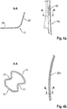
- Fig. 4a shows an A-pillar 18a with its viewing aperture 68. Furthermore, a section along the line AA is shown, in which the two legs 66, 66 'of the corner profile can be seen. The legs extend substantially straight from a rounded transition region 70.
- Fig. 4b shows a B-pillar 20a with her section AA.
- the cross section of the B-pillar 20a is hollow and has a substantially octagonal shape as a round double profile.
- the shape has two opposed waistlines 72, 72 'extending in a rounded portion 74 and a flattened portion 76.
- the sections 74 and 76 are bulged opposite the waist sections.
Landscapes
- Engineering & Computer Science (AREA)
- Transportation (AREA)
- Structural Engineering (AREA)
- Mechanical Engineering (AREA)
- Civil Engineering (AREA)
- Life Sciences & Earth Sciences (AREA)
- Geology (AREA)
- Chemical & Material Sciences (AREA)
- Combustion & Propulsion (AREA)
- Body Structure For Vehicles (AREA)
- Component Parts Of Construction Machinery (AREA)
Abstract
- einem von vier Säulen getragenen Fahrerschutzdach (17), von denen zwei als A-Säulen (18a, 18b) und zwei als B-Säulen (20a, 20b) ausgebildet sind,
- wobei jeweils eine Seitenwand (52) sich zwischen einer der A-Säulen (18a, 18b) und einer der B-Säulen (20a, 20b) erstreckt, eine Abschlusswand sich zwischen den B- Säulen (20a, 20b) und ein Einstiegsbereich (20) sich zwischen den A-Säulen (18a, 18b) erstreckt,
- die B-Säulen (20a, 20b) jeweils aus einem Rohrprofil und mindestens eine der A-Säulen (18a, 18b) aus einem Eckprofil gebildet ist, das zwei winkelig zueinander angeordnete Schenkel (66) aufweist.
Description
- Die vorliegende Erfindung betrifft eine Fahrerkabine für ein Flurförderzeug. Bei Flurförderzeugen unterschiedlicher Bauart und Einsatzart kann eine Fahrerkabine mit einem Platz für den Fahrzeugführer vorgesehen sein. Der Platz kann in einer Fahrerkabine beispielsweise als ein Sitzplatz oder auch als ein Fahrerstandplatz ausgebildet sein. Es ist bekannt, eine entsprechende Fahrerkabine mit einem Fahrerschutzdach auszustatten. Das Fahrerschutzdach hat einerseits die Aufgabe zu erfüllen, eine möglichst gute Sicht auf die angehobene Last zu gewähren und andererseits den Fahrer vor herunterstürzenden Gegenständen zu schützen. Die Fahrerkabine mit dem Fahrerschutzdach muss dafür ausreichend stabil ausgebildet sein.
- Aus dem Stand der Technik ist es bekannt, zwei Säulen an den Fahrzeugseiten des Antriebsteils vorzusehen. Diese Säulen können beispielsweise leicht nach vorn geneigt sein, wobei das Fahrerschutzdach dann als eine Krone mit einer entsprechenden Verstrebung ausgebildet ist.
- Aufgabe der vorliegenden Erfindung ist es, für ein Flurförderzeug eine Fahrerkabine bereitzustellen, die bei möglichst großer Stabilität eine gute Sichtbarkeit in das Arbeitsumfeld nach außen bietet.
- Erfindungsgemäß wird die Aufgabe durch eine Fahrerkabine mit den Merkmalen aus Anspruch 1 gelöst. Vorteilhafte Ausgestaltungen bilden die Gegenstände der Unteransprüche.
- Die erfindungsgemäße Fahrerkabine ist für ein Flurförderzeug vorgesehen, insbesondere für einen Schubmaststapler, bei dem eine Bedienperson durch ein Fahrerschutzdach abgesichert ist. Eine Besonderheit der erfindungsgemäßen Fahrerkabine besteht darin, dass das Fahrerschutzdach von vier Säulen getragen wird, wobei zwei als A-Säule und zwei als B-Säule ausgebildet sind. Da bei einem Flurförderzeug vorne und hinten und damit die Rolle der A- und der B-Säule nicht unmittelbar festgelegt ist, wird bei der erfindungsgemäßen Fahrerkabine definiert, dass die B-Säulen zu einem Lastteil des Flurförderzeugs weisen und zwischen diesen eine Abschlusswand angeordnet ist und dass zwischen den A-Säulen ein Einstiegsbereich vorgesehen ist.
- Bei der erfindungsgemäßen Fahrerkabine sind die B-Säulen als ein Rohrprofil ausgebildet, beispielsweise als ein im Querschnitt rundes, ovales Rohrprofil oder als rundes Doppelprofil mit einer taillenartigen Einschnürung. Mindestens eine, bevorzugt beide A-Säulen sind aus einem Eckprofil gebildet, das zwei winkelig zueinander angeordnete Schenkel aufweist. Das Eckprofil ist als ein offenes Profil ausgestaltet, das zwei winkelig zueinander angeordnete, jeweils flache Schenkel aufweist. Der Vorteil der erfindungsgemäßen Fahrerkabine besteht darin, dass in der Verwendung des Eckprofils ein Profil zum Einsatz kommt, das eine Sicht aus der Fahrerkabine heraus auf den Arbeitsbereich und die Umgebung des Flurförderzeugs nur in s geringem Maße einschränkt. Anders als beispielsweise mit zwei breitflächigen Streben ausgestattete Fahrerkabinen, erzeugt ein Eckprofil mit zueinander im Winkel angeordneten Schenkeln eine deutlich geringere Einschränkung des Sichtfeldes. Auch die Verwendung von vier Säulen bewirkt, dass das für die Umsicht des Fahrers erforderliche Sichtfeld frei bleibt. Auch erlaubt die Steifigkeit des Eckprofils einen geringen Materialeinsatz, der ebenfalls zu einem freien Sichtfeld führt. Zudem verbraucht das Eckprofil wenig Platz, wodurch der Innenraum der Fahrerkabine gut genutzt werden kann. Bevorzugt ist das Eckprofil benachbart zu einem Fahrersitz oder einem Fahrerstandplatz positioniert.
- In einer bevorzugten Weiterbildung sind die Schenkel des Eckprofils als flache Schenkel ausgebildet, die über einen gerundeten Übergangsbereich miteinander verbunden sind. Der Übergangsbereich bildet eine Außenkante der Fahrerkabine. Das Eckprofil für die erfindungsgemäße Fahrerkabine besteht im Wesentlichen aus einem Flachmaterial, das ungefähr mittig einen gerundeten Übergangsbereich besitzt, wobei sich die davon abstehenden Schenkel flach fort erstrecken und bevorzugt in Profillängsrichtung einen konstanten Winkel zueinander einschließen. Bevorzugt sind beide A-Säulen als Eckprofil ausgebildet, die A-Säulen müssen dabei nicht identisch ausgebildet sein.
- In einer bevorzugten Weiterbildung sind Befestigungsmittel zur Befestigung der Fahrerkabine an einem Fahrzeugrahmen vorgesehen. Die Fahrerkabine ist in sich insgesamt ein fertig gebautes Schweißteil, das insgesamt als vormontierte Einheit an dem Fahrzeugrahmen des Flurförderzeugs befestigt wird. Bevorzugt können für diese Befestigung an dem dem Fahrerschutzdach gegenüberliegenden Ende an mindestens einem der Säulenpaare Befestigungsmittel, wie beispielsweise Ösen, Ringe, Öffnungen oder dergleichen vorgesehen sein, über die die Fahrerkabine montiert und am Fahrzeugrahmen befestigt wird.
- In einer weiter bevorzugten Ausgestaltung ist das Fahrerschutzdach mit einem U-förmigen Flachprofil ausgebildet. Auf den Schenkeln des U-förmigen Flachprofils ist jeweils ein aufrecht stehendes Halteprofil angeordnet, an denen jeweils die Enden von zwischen den Schenkeln verlaufenden Querprofilen gehalten sind. Die Halteprofile können durch abgekantete Ränder des Flachprofils gebildet sein. Wie bei Fahrerschutzdächern bekannt, sind die Querprofile schräg gegenüber der Vertikalen an den stehenden Halteprofilen befestigt, so dass ein schräg nach oben gerichteter Blick nicht auf die Breitseite der Querstreben fällt, sondern diese nur teilweise oder bevorzugt nur an ihrer Schmalseite den Blick nach oben versperren. Alternativ kann auch ein Panoramadach aus Glas auf dem U-förmigen Flachprofil aufliegen.
- In einer weiter bevorzugten Ausgestaltung verbindet ein Abschlussprofil die freien Schenkel des U-förmigen Profils. Auf diese Weise entsteht ein umlaufender Dachrahmen für das Fahrerschutzdach. Bevorzugt ist dieser umlaufende Dachrahmen mit den vier Säulen verbunden, wobei hierzu noch ein weiteres umlaufendes Rahmenprofil den Dachrahmen aus U-förmigem Profil und Abschlussprofil umgeben kann. In einer bevorzugten Weiterbildung weist jede der beiden Seitenwände ein Zwischenblech auf, das endseitig mit A-Säule und B-Säule verbunden ist. Das Zwischenblech dient als Kern für den Aufbau der Seitenwand, die mit dem Zwischenblech im Zentrum eine Art von Sandwichstruktur bildet.
- In einer bevorzugten Weiterbildung ist auf der zur Außenseite der Fahrerkabine weisenden Seite des Zwischenblechs ein bündig mit der A-Säule abschließendes oberes Verkleidungsblech angebracht. Insbesondere an dem Eckprofil schließt das obere Verkleidungsblech bündig mit einer der A-Säulen und ihrem Schenkel ab. Alternativ kann das obere Verkleidungsblech auch einstückig mit einem der Schenkel einer der A-Säulen ausgebildet sein. Indem das Zwischenblech an seine Befestigung an der A-Säule auf der Innenseite des Schenkels des Eckprofils angebracht ist, springt das Zwischenblech zurück, so dass das obere Verkleidungsblech bündig mit der A-Säule abschließen kann. Ferner ist auf der zum Innenraum der Fahrerkabine weisenden Seite des Trägerblechs ein unteres Verkleidungsblech unter Bildung einer Fuge gegenüber dem oberen Verkleidungsblech angebracht. Der besondere Vorteil eines nach innen versetzten Trägerblechs, an dem das untere Verkleidungsblech befestigt ist, besteht darin, dass das Trägerblech weiter innenliegend angebracht ist und das untere Verkleidungsblech so eine tiefere Fuge, insbesondere gegenüber dem oberen Verkleidungsblech, besitzt.
- Auch im Bereich des Einstiegs in die Fahrerkabine kann auf einer Seite eine A-Säule mit einem Einstiegsblech ausgestattet sein. Der Einstiegsbereich ist dabei bevorzugt durch eine der A-Säulen begrenzt und auf seiner gegenüberliegenden Seite durch das an der anderen A-Säule angebrachte Einstiegsblech. Grundsätzlich sind auch Einstiegsbereiche möglich, bei denen Einstiegsbleche an beiden Seiten der A-Säule angebracht sind.
- In einer bevorzugten Ausgestaltung der Fahrerkabine sind die Säulen mit dem Fahrerschutzdach und mit dem Zwischenblech der anderen Seitenwände verschweißt. Die Fahrerkabine bildet insgesamt eine Schweißkonstruktion, wobei durch den Einstiegsbereich lediglich die beiden A-Säulen an ihrem von dem Fahrerschutzdach fortweisenden Ende nicht direkt miteinander verbunden ist, sondern über einen Einstiegsträger.
- In einer bevorzugten Weiterbildung besitzt die Abschlusswand einen Halteabschnitt für eine Fahrschutzscheibe. Die Abschlusswand der Fahrerkabine bildet den Übergang vom Antriebsteil zu einem Lastteil des Flurförderzeugs. Insbesondere bei Schubmaststaplern, aber auch bei anderen Flurförderzeugen mit einem Hubmast ist eine den Bereich zwischen Fahrerkabine und Lastteil zumindest teilweise bedeckende Fahrerschutzscheibe vorgesehen, die ein Hereingreifen oder einen sonstigen Kontakt mit dem Hubmast aus der Fahrerkabine heraus verhindert.
- Für eine weitere Verbesserung der Sicht des Fahrers kann in mindestens einer der A-Säulen eine Sichtdurchbrechung vorgesehen sein. Diese ist bevorzugt mittig im gerundeten Übergangsbereich der A-Säule vorgesehen. Ist nur eine A-Säule als Eckprofil ausgebildet, so ist dieses bevorzugt benachbart zu einem Fahrplatz, insbesondere einem Fahrersitz oder einem Fahrerstandplattform ausgebildet.
- Ein bevorzugtes Ausführungsbeispiel der erfindungsgemäßen Fahrerkabine wird anhand der nachfolgenden Figuren näher vorgestellt. Es zeigen:
- Fig. 1
- eine perspektivische Ansicht von schräg oben auf eine Fahrerkabine,
- Fig. 2
- eine perspektivische Ansicht einer noch nicht montierten Fahrerkabine mit Fahrerschutzdach,
- Fig. 3
- eine Ansicht der Fahrerkabine mit einem Blick durch den Eingangsbereich auf eine Innenseite der Seitenwand und
- Fig. 4a, b
- jeweils eine A-Säule und eine B-Säule im Schnitt.
-
Fig. 1 zeigt ein Flurförderzeug 10, das als ein Schubmaststapler ausgebildet ist. Das Flurförderzeug besitzt einen Schubmast 12, der entlang der Radarme 14 verstellbar ist. - Eine Fahrerkabine 16 besitzt ein Fahrerschutzdach (in
Fig. 1 nur unvollständig gezeigt), das von vier Säulen 18a, 18b, 20a, 20b getragen ist. Bezogen auf den Schubmast 12 werden die Säulen 20a, 20b als B-Säulen bezeichnet. Die B-Säulen 20a, 20b bestehen aus einem rohrförmigen Profil, das einen runden Querschnitt besitzt. Die den Einstiegsbereich 20 begrenzenden Säulen 18a, 18b werden nachfolgend als A-Säulen bezeichnet. Die Unterscheidung in A-Säulen und B-Säulen ist für das Flurförderzeug 10 willkürlich, ohne Bezug auf eine Fahrtrichtung festgelegt, da das Fahrzeug während seines regulären Einsatzes in beide Richtungen R und R' verfährt. Die beiden A-Säulen sind als Eckprofile ausgebildet, die flache Schenkel 19b und 19'b aufweisen. Beide Schenkel 19b und 19'b stehen mindestens in einem rechten Winkel, bevorzugt in einem Winkel von 100° bis 130° zueinander. In dem Ausführungsbeispiel sind beide A-Säulen als Eckprofile ausgebildet, wenn nur ein Eckprofil vorgesehen ist, dann ist bevorzugt die fahrernahe A-Säule als Eckprofil ausgebildet. - In Inneren der Fahrerkabine ist ein Fahrerplatz vorgesehen, der einen Fahrersitz 22 mit Fußpedalen 24, Lenkrad 26 und Bedienanzeige 28 besitzt. Auf der zum Schubmast weisenden Seite ist neben dem Fahrersitz 22 ferner ein Handbediengerät 30 vorgesehen. Der Fahrerplatz im Inneren der Fahrerkabine kann über eine Stufe 32 betreten werden, wobei seitlich an den A-Säulen angebrachte Handgriffe 34 helfen.
Fig. 2 zeigt die noch nicht in das Fahrzeug eingebaute Fahrerkabine mit einem Blick auf den Einstiegsbereich 20, der von den A-Säulen 18a, 18b begrenzt wird. Der Einstiegsbereich 20 wird seitlich von einem Einstiegsblech 36 begrenzt. Das Einstiegsblech 36 ist mit der A-Säule 18b verbunden. Zudem ist ein inFig. 2 nicht gezeigter Einstiegsträger vorgesehen, mit dem die A-Säule 18b mit der A-Säule 18a bzw. mit dem Einstiegsblech 36 verbunden ist. - In
Fig. 2 ist der nähere Aufbau des Fahrerschutzdachs 17 zu erkennen. Demnach sind die beiden Halteprofile 38, 40 aufrecht stehend angeordnet. Zwischen den Halteprofilen 38 und 40 sind zwei Querprofile 42 und 44 gespannt. Die Halteprofile 38, 40 sind senkrecht aus einem U-förmigen Flachblech 46 hochgebogen. Flachblech 46 bildet ein Kantteil. Die Querprofile 42, 44 sind in den Halteprofilen 38 und 40 schräg geneigt gegenüber der Senkrechten angeordnet. - In
Fig. 2 ist ferner ein Halteabschnitt 48 zu erkennen, an dem eine Schutzscheibe für den Fahrer angebracht werden kann. Der ebenfalls dargestellte Komponentenbereich 50 dient dazu, für den Betrieb des Flurförderzeugs notwendige Komponenten gegenüber dem Innenraum abzugrenzen. Der Komponentenbereich 50 erstreckt sich von einer Rückwand der Fahrerkabine in den Kabineninnenraum. - In
Fig. 2 ist ebenfalls der Aufbau einer Seitenwand 52 zu erkennen, die ein Verkleidungsblech 54 besitzt, das im Wesentlichen bündig mit der A-Säule 18a abschließt. Ebenfalls zu erkennen ist ein Trägerblech 56, das in der dargestellten Ausführung unterhalb des Verkleidungsblechs 54 die Seitenwand bildet. Nicht dargestellt inFig. 2 ist ein unteres Verkleidungsblech, das an dem Trägerblech 56 befestigt wird. Oberes Verkleidungsblech 54 und unteres Verkleidungsblech 56 besitzen dabei gegeneinander eine besonders tiefe Fuge. - In
Fig. 2 ferner zu erkennen sind Befestigungsmittel 58, über die die Fahrerkabine mit dem Fahrzeugrahmen befestigt werden kann. Die Befestigungsmittel sind hier in Form von Ösen oder Ringen ausgebildet. -
Fig. 3 zeigt eine weitere Ansicht der Fahrerkabine. Für das Fahrerschutzdach 17 ist das U-förmige Flachprofil 46 mit seinen abgekanteten Halteprofilen 38, 40 zu erkennen. Die freien Enden des U-förmigen Flachprofils 46 werden über ein Abschlussprofil 62 miteinander verbunden. Bei einer Ausgestaltung als Panoramadach ist das U-förmige Flachprofil zur Strebe 62 hin geschlossen, um eine Auflage für den Kleber und eine Panoramascheibe zu schaffen. Im Hinblick auf den Aufbau der Seitenwand zeigt das Detail A die Verwendung eines Zwischenblechs 64, das mit der A-Säule 18a flächig verschweißt ist. Detail B zeigt nur das Zwischenblech 64 in seiner angeschweißten Position, wobei das Zwischenblech 64 an einem Schenkel 66 des Eckprofils angeschweißt ist. An das Zwischenblech 64 wird von außen das obere Verkleidungsblech 54 befestigt, bevorzugt geschweißt. Auch ist es möglich, das obere Verkleidungsblech 54 einstückig mit einem Schenkel der angrenzenden A-Säule auszubilden. Innenseitig wird an dem Zwischenblech 64 ein Trägerblech 56 angeschweißt. Ein besonderer Effekt des weiter innenliegenden Trägerblechs 56 ist, dass das untere Verkleidungsteil, das an dem Trägerblech 56 befestigt wird und unterhalb des oberen Verkleidungsteils 54 liegt, weiter zurückspringend seine Befestigung erfährt und somit eine besonders tiefe Fuge zwischen den oberen Verkleidungsteilen und dem unteren Verkleidungsteil gebildet werden kann. - Bei der vorstehend erläuterten Fahrerkabine spielen eine Reihe von Effekten zusammen, um für den Fahrer eine gute Sicht bereitzustellen. Ein Aspekt ist, dass durch die gebogene Form der A-Säulen 18a, 18b bei größtmöglicher Stabilität nur ein kleiner Winkelbereich für den Fahrer in seiner Sicht verdeckt wird. Zusätzlich ist es ohne Einbußen der Stabilität möglich, eine Sichtdurchbrechung 68 vorzusehen. Auch ist es möglich, die Seitenwände aufgrund der stabilisierenden Wirkung des Zwischenblechs und der zusätzlichen Aussteifung durch das Trägerblech relativ weit in Richtung des Fahrzeugrahmens herunterzuziehen, so dass auch hierdurch ein großes Sichtfeld entsteht.
-
Fig. 4a zeigt eine A-Säule 18a mit ihrer Sichtdurchbrechung 68. Ferner ist ein Schnitt entlang der Linie A-A dargestellt, in dem die beiden Schenkel 66, 66' des Eckprofils zu erkennen sind. Die Schenkel erstrecken sich im Wesentlichen gerade von einem abgerundeten Übergangsbereich 70. -
Fig. 4b zeigt eine B-Säule 20a mit ihrem Schnitt A-A. Der Querschnitt der B-Säule 20a ist hohl und besitzt eine im Wesentlichen achtförmige Gestalt als ein rundes Doppelprofil. Die Gestalt besitzt zwei einander gegenüberliegende Taillen 72, 72', die sich in einem abgerundeten Abschnitt 74 und einem abgeflachten Abschnitt 76 erstrecken. Die Abschnitte 74 und 76 sind gegenüber den Taillenabschnitten ausgebaucht. -
- 10
- Flurförderzeug
- 12
- Schubmast
- 14
- Radarme
- 16
- Fahrerkabine
- 17
- Fahrerschutzdach
- 18a,b
- A-Säulen
- 19b, 19'b
- Schenkel
- 20
- Einstiegsbereich
- 20a,b
- B-Säulen
- 22
- Fahrersitz
- 24
- Fußpedalen
- 26
- Lenkrad
- 28
- Bedienanzeige
- 30
- Handbediengerät
- 32
- Stufe
- 34
- Handgriffe
- 36
- Einstiegsblech
- 38
- Halteprofil
- 40
- Halteprofil
- 42
- Querprofil
- 44
- Querprofil
- 46
- U-förmiges Flachprofil
- 48
- Halteabschnitt
- 50
- Begrenzungsbereich
- 52
- Seitenwand
- 54
- oberes Verkleidungsblech
- 56
- Trägerblech
- 58
- Befestigungsmittel
- 62
- Abschlussprofil
- 64
- Zwischenblech
- 66, 66'
- Schenkel
- 68
- Sichtdurchbrechung
- 70
- Übergangsbereich
- 72, 72'
- Taille
- 74
- abgerundeter Abschnitt
- 76
- abgeflachter Abschnitt
Claims (15)
- Fahrerkabine für ein Flurförderzeug (10) mit- einem von vier Säulen getragenen Fahrerschutzdach (17), von denen zwei als A-Säulen (18a, 18b) und zwei als B-Säulen (20a, 20b) ausgebildet sind,- wobei jeweils eine Seitenwand (52) sich zwischen einer der A-Säulen (18a, 18b) und einer der B-Säulen (20a, 20b) erstreckt, eine Abschlusswand sich zwischen den B-Säulen (20a, 20b) und ein Einstiegsbereich (20) sich zwischen den A-Säulen (18a, 18b) erstreckt,- die B-Säulen (20a, 20b) jeweils aus einem Rohrprofil und mindestens eine der A-Säulen (18a, 18b) aus einem Eckprofil gebildet ist, das zwei winkelig zueinander angeordnete Schenkel (66) aufweist.
- Fahrerkabine nach Anspruch 1, dadurch gekennzeichnet, dass beide A-Säulen als ein Eckprofil ausgebildet sind, von denen jedes zwei winkelig zueinander angeordnete Schenkel aufweist.
- Fahrerkabine nach Anspruch 1 oder 2, dadurch gekennzeichnet, dass die Schenkel des oder der Eckprofile als flache Schenkel (66) ausgebildet sind, die über einen gerundeten Übergangsbereich miteinander verbunden sind, der eine Außenkante der Fahrerkabine bildet.
- Fahrerkabine nach einem der Ansprüche 1 bis 3, dadurch gekennzeichnet, dass mindestens ein Befestigungsmittel (58) zur Befestigung der Fahrerkabine an einem Fahrzeugrahmen vorgesehen ist.
- Fahrerkabine nach einem der Ansprüche 1 bis 4, dadurch gekennzeichnet, dass das Fahrerschutzdach (17) ein U-förmiges Flachprofil (46) aufweist, dessen Schenkeln jeweils ein aufrecht stehendes Halteprofil (38, 40) bilden, an denen jeweils die Enden von zwischen den Schenkeln verlaufenden Querprofilen (42, 44) gehalten sind.
- Fahrerkabine nach Anspruch 5, dadurch gekennzeichnet, dass ein Abschlussprofil (62) die freien Schenkel des U-förmigen Flachprofils (46) miteinander verbindet und einen umlaufenden Dachrahmen bildet.
- Fahrerkabine nach einem der Ansprüche 1 bis 6, dadurch gekennzeichnet, dass jede der Seitenwände (52) ein endseitig mit A-Säule (18a, 18b) und B-Säule (20a, 20b) verbundenes Zwischenblech (66) aufweist, an dem auf der zum Innenraum der Fahrerkabine weisenden Seite ein Trägerblech (56) angebracht ist.
- Fahrerkabine nach Anspruch 7, dadurch gekennzeichnet, dass auf der zur Außenseite der Fahrerkabine weisenden Seite des Zwischenblechs (66) ein bündig mit der A-Säule abschließendes oberes Verkleidungsblech (54) angebracht ist.
- Fahrerkabine nach Anspruch 7 oder 8, dadurch gekennzeichnet, dass auf der zur Außenseite der Fahrerkabine weisenden Seite des Trägerblechs (56) ein unteres Verkleidungsblech unter Bildung einer Fuge gegenüber dem oberen Verkleidungsblech (54) angebracht ist.
- Fahrerkabine nach einem der Ansprüche 1 bis 9, dadurch gekennzeichnet, dass der Einstiegsbereich (20) auf einer Seite durch eine der A-Säulen (18a, 18b) begrenzt und auf der anderen Seite durch ein an der anderen A-Säule (18a, 18b) angebrachtes Einstiegsblech (36) begrenzt ist.
- Fahrerkabine nach einem der Ansprüche 1 bis 10, dadurch gekennzeichnet, dass die Säulen mit dem Fahrerschutzdach (17) verschweißt sind.
- Fahrerkabine nach einem der Ansprüche 1 bis 11, dadurch gekennzeichnet, dass die A-Säulen mit den Zwischenblechen (64) der Seitenwände und die B-Säulen mit dem Verkleidungsblech (54) und dem Trägerblech (56) verschweißt sind.
- Fahrerkabine nach einem der Ansprüche 1 bis 12, dadurch gekennzeichnet, dass die Abschlusswand einen Halteabschnitt (48) für eine Fahrerschutzscheibe aufweist.
- Fahrerkabine nach einem der Ansprüche 1 bis 13, dadurch gekennzeichnet, dass in mindestens einer der A-Säulen (18a, 18b) eine Sichtdurchbrechung (68) vorgesehen ist.
- Fahrerkabine nach einem der Ansprüche 1 bis 14, dadurch gekennzeichnet, dass die als Eckprofil ausgebildete A-Säule benachbart zu einem Fahrerplatz angeordnet ist.
Applications Claiming Priority (1)
| Application Number | Priority Date | Filing Date | Title |
|---|---|---|---|
| DE102018101531.3A DE102018101531A1 (de) | 2018-01-24 | 2018-01-24 | Fahrerkabine für ein Flurförderzeug |
Publications (2)
| Publication Number | Publication Date |
|---|---|
| EP3517482A1 true EP3517482A1 (de) | 2019-07-31 |
| EP3517482B1 EP3517482B1 (de) | 2022-08-24 |
Family
ID=65023783
Family Applications (1)
| Application Number | Title | Priority Date | Filing Date |
|---|---|---|---|
| EP19151621.0A Active EP3517482B1 (de) | 2018-01-24 | 2019-01-14 | Fahrerkabine für ein flurförderzeug |
Country Status (4)
| Country | Link |
|---|---|
| US (1) | US11021352B2 (de) |
| EP (1) | EP3517482B1 (de) |
| CN (2) | CN121180908A (de) |
| DE (1) | DE102018101531A1 (de) |
Families Citing this family (7)
| Publication number | Priority date | Publication date | Assignee | Title |
|---|---|---|---|---|
| JP7195105B2 (ja) * | 2018-10-09 | 2022-12-23 | 株式会社小松製作所 | キャブ及び作業機械 |
| CN110254533A (zh) * | 2019-07-31 | 2019-09-20 | 安徽合力股份有限公司 | 一种叉车驾驶室 |
| USD955295S1 (en) * | 2020-04-30 | 2022-06-21 | Shem, Llc | Vehicle cab |
| USD970394S1 (en) * | 2020-05-05 | 2022-11-22 | Shem, Llc | Vehicle cab |
| USD980145S1 (en) | 2020-05-05 | 2023-03-07 | Shem, Llc | Door for a vehicle |
| USD961468S1 (en) | 2020-05-05 | 2022-08-23 | Shem, Llc | Hood |
| DE102022133718A1 (de) * | 2022-12-16 | 2024-06-27 | Jungheinrich Aktiengesellschaft | Fahrerschutzeinrichtung für ein Flurförderzeug |
Citations (3)
| Publication number | Priority date | Publication date | Assignee | Title |
|---|---|---|---|---|
| US4411464A (en) * | 1981-08-03 | 1983-10-25 | Clark Equipment Company | Operator protective posts |
| DE10312432A1 (de) * | 2002-04-10 | 2003-12-04 | Linde Ag | Flurförderzeug mit einem Rahmen |
| US20080001435A1 (en) * | 2006-06-29 | 2008-01-03 | Crown Equipment Corporation | Overhead guard for materials handling vehicle |
Family Cites Families (16)
| Publication number | Priority date | Publication date | Assignee | Title |
|---|---|---|---|---|
| US4770263A (en) * | 1985-12-25 | 1988-09-13 | Nissan Motor Co., Ltd. | Body constuction of industrial vehicle |
| US5190435A (en) * | 1988-11-29 | 1993-03-02 | Washington Chain And Supply, Inc. | Fork lift truck |
| JP3779454B2 (ja) * | 1997-12-04 | 2006-05-31 | 日立建機株式会社 | 建設機械の運転室 |
| US6182797B1 (en) * | 1998-03-17 | 2001-02-06 | Crown Equipment Corporation | Enhanced visibility rider reach fork lift truck |
| DE10013065A1 (de) * | 2000-03-17 | 2001-09-20 | Still Gmbh | Kabine eines Flurförderzeugs |
| EP1666343B1 (de) * | 2003-09-09 | 2009-07-15 | Komatsu Ltd. | Kabine von baumaschine |
| JP2005119362A (ja) * | 2003-10-14 | 2005-05-12 | Hitachi Constr Mach Co Ltd | 建設機械 |
| US7062828B2 (en) * | 2004-02-12 | 2006-06-20 | Daimlerchrysler Corporation | Cab to frame alignment tool |
| JP4852912B2 (ja) * | 2005-07-15 | 2012-01-11 | 株式会社豊田自動織機 | 産業車両 |
| ITTO20050716A1 (it) * | 2005-10-10 | 2007-04-11 | Mariotti S R L V | Carrello elevatore ad azionamento elettrico e procedimento per la sua produzione |
| CN103104003A (zh) * | 2011-11-11 | 2013-05-15 | 扬州丰登精密机械有限公司 | 挖掘机驾驶室的前窗大视野框架结构 |
| US9841555B2 (en) * | 2014-09-29 | 2017-12-12 | Corning Incorporated | Optical transmission systems and methods using a QSM large-effective-area optical fiber |
| KR101717059B1 (ko) * | 2015-07-01 | 2017-03-16 | 가부시키가이샤 고마쓰 세이사쿠쇼 | 작업 차량의 캡 및 그 제조 방법 |
| JP6597216B2 (ja) * | 2015-11-16 | 2019-10-30 | いすゞ自動車株式会社 | 車両のキャブ |
| EP3282339B1 (de) * | 2016-10-21 | 2020-01-15 | Komatsu, Ltd. | Nutzfahrzeug |
| CN206466036U (zh) * | 2017-02-27 | 2017-09-05 | 安徽江淮汽车集团股份有限公司 | 新型驾驶室前悬置安装机构 |
-
2018
- 2018-01-24 DE DE102018101531.3A patent/DE102018101531A1/de not_active Withdrawn
-
2019
- 2019-01-14 EP EP19151621.0A patent/EP3517482B1/de active Active
- 2019-01-24 CN CN202511725325.0A patent/CN121180908A/zh active Pending
- 2019-01-24 CN CN201910065445.0A patent/CN110065905A/zh active Pending
- 2019-01-24 US US16/255,959 patent/US11021352B2/en active Active
Patent Citations (3)
| Publication number | Priority date | Publication date | Assignee | Title |
|---|---|---|---|---|
| US4411464A (en) * | 1981-08-03 | 1983-10-25 | Clark Equipment Company | Operator protective posts |
| DE10312432A1 (de) * | 2002-04-10 | 2003-12-04 | Linde Ag | Flurförderzeug mit einem Rahmen |
| US20080001435A1 (en) * | 2006-06-29 | 2008-01-03 | Crown Equipment Corporation | Overhead guard for materials handling vehicle |
Also Published As
| Publication number | Publication date |
|---|---|
| EP3517482B1 (de) | 2022-08-24 |
| DE102018101531A1 (de) | 2019-07-25 |
| CN110065905A (zh) | 2019-07-30 |
| US11021352B2 (en) | 2021-06-01 |
| CN121180908A (zh) | 2025-12-23 |
| US20190225468A1 (en) | 2019-07-25 |
Similar Documents
| Publication | Publication Date | Title |
|---|---|---|
| EP3517482B1 (de) | Fahrerkabine für ein flurförderzeug | |
| DE4008896C2 (de) | Motorraumaufbau eines Kraftfahrzeuges | |
| DE4421095B4 (de) | Seitenstruktur einer Fahrzeugkarosserie | |
| DE60001403T2 (de) | Kabinerahmen für landwirtschaftliche Maschine | |
| DE3836808C2 (de) | ||
| DE112015000096B4 (de) | Kabine für ein Arbeitsfahrzeug und Verfahren für deren Herstellung | |
| DE3810867C2 (de) | Frontkarosseriekonstruktion eines Kraftfahrzeugs | |
| DE10028716A1 (de) | Karosserieseitenteilkonstruktion für ein Automobil | |
| DE102016106720B4 (de) | Fahrzeugfrontstruktur | |
| DE112005001689B4 (de) | Baumaschinenführerhaus | |
| DE2638440A1 (de) | Ueberschlagschutzrahmen fuer kraftfahrzeuge | |
| DE102005012543B4 (de) | Aufbaustruktur für einen mit einem Fließheck versehenen Personenkraftwagen | |
| WO2005095184A1 (de) | Kraftfahrzeug mit seitenaufprallverstärkung | |
| DE2056713A1 (de) | Kraftfahrzeugrahmen | |
| DE102015202080B4 (de) | Karosseriestruktur für ein Fahrzeug | |
| DE19805804B4 (de) | Fahrzeugkarosserie | |
| EP1431092B1 (de) | Fahrzeugdach mit einem Schiebedach | |
| DE602006000101T2 (de) | Längsträger und Struktur eines Kraftfahrzeuges mit so einem Längsträger | |
| DE3518899A1 (de) | Rammschutz mit aufklappbarem teil, insbesondere fuer lastkraftfahrzeuge | |
| DE202018006748U1 (de) | Fahrerkabine für ein Flurförderzeug | |
| DE102004010161B4 (de) | Fahrzeugkarosserie eines Cabrios mit einer linken und einer rechten A-Säule | |
| DE2219972A1 (de) | Schutzdachaufbau und fahrerhaus fuer arbeitsmaschinen, insbesondere gabelstapler | |
| DE10359514B4 (de) | Dachaufsatz für ein Fahrerhaus eines Nutzfahrzeugs | |
| DE19813094A1 (de) | Fahrzeugkarosserie mit zwei A-Säulen | |
| DE19961822C2 (de) | Kraftfahrzeugrahmen mit einer Verstärkungsstruktur |
Legal Events
| Date | Code | Title | Description |
|---|---|---|---|
| PUAI | Public reference made under article 153(3) epc to a published international application that has entered the european phase |
Free format text: ORIGINAL CODE: 0009012 |
|
| STAA | Information on the status of an ep patent application or granted ep patent |
Free format text: STATUS: THE APPLICATION HAS BEEN PUBLISHED |
|
| AK | Designated contracting states |
Kind code of ref document: A1 Designated state(s): AL AT BE BG CH CY CZ DE DK EE ES FI FR GB GR HR HU IE IS IT LI LT LU LV MC MK MT NL NO PL PT RO RS SE SI SK SM TR |
|
| AX | Request for extension of the european patent |
Extension state: BA ME |
|
| STAA | Information on the status of an ep patent application or granted ep patent |
Free format text: STATUS: REQUEST FOR EXAMINATION WAS MADE |
|
| 17P | Request for examination filed |
Effective date: 20200122 |
|
| RBV | Designated contracting states (corrected) |
Designated state(s): AL AT BE BG CH CY CZ DE DK EE ES FI FR GB GR HR HU IE IS IT LI LT LU LV MC MK MT NL NO PL PT RO RS SE SI SK SM TR |
|
| GRAP | Despatch of communication of intention to grant a patent |
Free format text: ORIGINAL CODE: EPIDOSNIGR1 |
|
| STAA | Information on the status of an ep patent application or granted ep patent |
Free format text: STATUS: GRANT OF PATENT IS INTENDED |
|
| INTG | Intention to grant announced |
Effective date: 20220610 |
|
| GRAS | Grant fee paid |
Free format text: ORIGINAL CODE: EPIDOSNIGR3 |
|
| GRAA | (expected) grant |
Free format text: ORIGINAL CODE: 0009210 |
|
| STAA | Information on the status of an ep patent application or granted ep patent |
Free format text: STATUS: THE PATENT HAS BEEN GRANTED |
|
| AK | Designated contracting states |
Kind code of ref document: B1 Designated state(s): AL AT BE BG CH CY CZ DE DK EE ES FI FR GB GR HR HU IE IS IT LI LT LU LV MC MK MT NL NO PL PT RO RS SE SI SK SM TR |
|
| REG | Reference to a national code |
Ref country code: CH Ref legal event code: EP |
|
| REG | Reference to a national code |
Ref country code: DE Ref legal event code: R096 Ref document number: 502019005370 Country of ref document: DE |
|
| REG | Reference to a national code |
Ref country code: IE Ref legal event code: FG4D Free format text: LANGUAGE OF EP DOCUMENT: GERMAN |
|
| REG | Reference to a national code |
Ref country code: AT Ref legal event code: REF Ref document number: 1513546 Country of ref document: AT Kind code of ref document: T Effective date: 20220915 |
|
| REG | Reference to a national code |
Ref country code: LT Ref legal event code: MG9D |
|
| REG | Reference to a national code |
Ref country code: SE Ref legal event code: TRGR |
|
| REG | Reference to a national code |
Ref country code: NL Ref legal event code: MP Effective date: 20220824 |
|
| PG25 | Lapsed in a contracting state [announced via postgrant information from national office to epo] |
Ref country code: RS Free format text: LAPSE BECAUSE OF FAILURE TO SUBMIT A TRANSLATION OF THE DESCRIPTION OR TO PAY THE FEE WITHIN THE PRESCRIBED TIME-LIMIT Effective date: 20220824 Ref country code: PT Free format text: LAPSE BECAUSE OF FAILURE TO SUBMIT A TRANSLATION OF THE DESCRIPTION OR TO PAY THE FEE WITHIN THE PRESCRIBED TIME-LIMIT Effective date: 20221226 Ref country code: NO Free format text: LAPSE BECAUSE OF FAILURE TO SUBMIT A TRANSLATION OF THE DESCRIPTION OR TO PAY THE FEE WITHIN THE PRESCRIBED TIME-LIMIT Effective date: 20221124 Ref country code: NL Free format text: LAPSE BECAUSE OF FAILURE TO SUBMIT A TRANSLATION OF THE DESCRIPTION OR TO PAY THE FEE WITHIN THE PRESCRIBED TIME-LIMIT Effective date: 20220824 Ref country code: LV Free format text: LAPSE BECAUSE OF FAILURE TO SUBMIT A TRANSLATION OF THE DESCRIPTION OR TO PAY THE FEE WITHIN THE PRESCRIBED TIME-LIMIT Effective date: 20220824 Ref country code: LT Free format text: LAPSE BECAUSE OF FAILURE TO SUBMIT A TRANSLATION OF THE DESCRIPTION OR TO PAY THE FEE WITHIN THE PRESCRIBED TIME-LIMIT Effective date: 20220824 Ref country code: FI Free format text: LAPSE BECAUSE OF FAILURE TO SUBMIT A TRANSLATION OF THE DESCRIPTION OR TO PAY THE FEE WITHIN THE PRESCRIBED TIME-LIMIT Effective date: 20220824 |
|
| PG25 | Lapsed in a contracting state [announced via postgrant information from national office to epo] |
Ref country code: PL Free format text: LAPSE BECAUSE OF FAILURE TO SUBMIT A TRANSLATION OF THE DESCRIPTION OR TO PAY THE FEE WITHIN THE PRESCRIBED TIME-LIMIT Effective date: 20220824 Ref country code: IS Free format text: LAPSE BECAUSE OF FAILURE TO SUBMIT A TRANSLATION OF THE DESCRIPTION OR TO PAY THE FEE WITHIN THE PRESCRIBED TIME-LIMIT Effective date: 20221224 Ref country code: HR Free format text: LAPSE BECAUSE OF FAILURE TO SUBMIT A TRANSLATION OF THE DESCRIPTION OR TO PAY THE FEE WITHIN THE PRESCRIBED TIME-LIMIT Effective date: 20220824 Ref country code: GR Free format text: LAPSE BECAUSE OF FAILURE TO SUBMIT A TRANSLATION OF THE DESCRIPTION OR TO PAY THE FEE WITHIN THE PRESCRIBED TIME-LIMIT Effective date: 20221125 |
|
| PG25 | Lapsed in a contracting state [announced via postgrant information from national office to epo] |
Ref country code: SM Free format text: LAPSE BECAUSE OF FAILURE TO SUBMIT A TRANSLATION OF THE DESCRIPTION OR TO PAY THE FEE WITHIN THE PRESCRIBED TIME-LIMIT Effective date: 20220824 Ref country code: RO Free format text: LAPSE BECAUSE OF FAILURE TO SUBMIT A TRANSLATION OF THE DESCRIPTION OR TO PAY THE FEE WITHIN THE PRESCRIBED TIME-LIMIT Effective date: 20220824 Ref country code: ES Free format text: LAPSE BECAUSE OF FAILURE TO SUBMIT A TRANSLATION OF THE DESCRIPTION OR TO PAY THE FEE WITHIN THE PRESCRIBED TIME-LIMIT Effective date: 20220824 Ref country code: DK Free format text: LAPSE BECAUSE OF FAILURE TO SUBMIT A TRANSLATION OF THE DESCRIPTION OR TO PAY THE FEE WITHIN THE PRESCRIBED TIME-LIMIT Effective date: 20220824 |
|
| REG | Reference to a national code |
Ref country code: DE Ref legal event code: R097 Ref document number: 502019005370 Country of ref document: DE |
|
| PG25 | Lapsed in a contracting state [announced via postgrant information from national office to epo] |
Ref country code: SK Free format text: LAPSE BECAUSE OF FAILURE TO SUBMIT A TRANSLATION OF THE DESCRIPTION OR TO PAY THE FEE WITHIN THE PRESCRIBED TIME-LIMIT Effective date: 20220824 Ref country code: EE Free format text: LAPSE BECAUSE OF FAILURE TO SUBMIT A TRANSLATION OF THE DESCRIPTION OR TO PAY THE FEE WITHIN THE PRESCRIBED TIME-LIMIT Effective date: 20220824 |
|
| PG25 | Lapsed in a contracting state [announced via postgrant information from national office to epo] |
Ref country code: AL Free format text: LAPSE BECAUSE OF FAILURE TO SUBMIT A TRANSLATION OF THE DESCRIPTION OR TO PAY THE FEE WITHIN THE PRESCRIBED TIME-LIMIT Effective date: 20220824 |
|
| PLBE | No opposition filed within time limit |
Free format text: ORIGINAL CODE: 0009261 |
|
| STAA | Information on the status of an ep patent application or granted ep patent |
Free format text: STATUS: NO OPPOSITION FILED WITHIN TIME LIMIT |
|
| 26N | No opposition filed |
Effective date: 20230525 |
|
| P01 | Opt-out of the competence of the unified patent court (upc) registered |
Effective date: 20230628 |
|
| PG25 | Lapsed in a contracting state [announced via postgrant information from national office to epo] |
Ref country code: SI Free format text: LAPSE BECAUSE OF FAILURE TO SUBMIT A TRANSLATION OF THE DESCRIPTION OR TO PAY THE FEE WITHIN THE PRESCRIBED TIME-LIMIT Effective date: 20220824 |
|
| REG | Reference to a national code |
Ref country code: CH Ref legal event code: PL |
|
| GBPC | Gb: european patent ceased through non-payment of renewal fee |
Effective date: 20230114 |
|
| PG25 | Lapsed in a contracting state [announced via postgrant information from national office to epo] |
Ref country code: LU Free format text: LAPSE BECAUSE OF NON-PAYMENT OF DUE FEES Effective date: 20230114 |
|
| REG | Reference to a national code |
Ref country code: BE Ref legal event code: MM Effective date: 20230131 |
|
| PG25 | Lapsed in a contracting state [announced via postgrant information from national office to epo] |
Ref country code: LI Free format text: LAPSE BECAUSE OF NON-PAYMENT OF DUE FEES Effective date: 20230131 Ref country code: GB Free format text: LAPSE BECAUSE OF NON-PAYMENT OF DUE FEES Effective date: 20230114 Ref country code: CH Free format text: LAPSE BECAUSE OF NON-PAYMENT OF DUE FEES Effective date: 20230131 |
|
| PG25 | Lapsed in a contracting state [announced via postgrant information from national office to epo] |
Ref country code: BE Free format text: LAPSE BECAUSE OF NON-PAYMENT OF DUE FEES Effective date: 20230131 |
|
| PG25 | Lapsed in a contracting state [announced via postgrant information from national office to epo] |
Ref country code: IE Free format text: LAPSE BECAUSE OF NON-PAYMENT OF DUE FEES Effective date: 20230114 |
|
| PG25 | Lapsed in a contracting state [announced via postgrant information from national office to epo] |
Ref country code: MC Free format text: LAPSE BECAUSE OF FAILURE TO SUBMIT A TRANSLATION OF THE DESCRIPTION OR TO PAY THE FEE WITHIN THE PRESCRIBED TIME-LIMIT Effective date: 20220824 |
|
| PG25 | Lapsed in a contracting state [announced via postgrant information from national office to epo] |
Ref country code: MC Free format text: LAPSE BECAUSE OF FAILURE TO SUBMIT A TRANSLATION OF THE DESCRIPTION OR TO PAY THE FEE WITHIN THE PRESCRIBED TIME-LIMIT Effective date: 20220824 |
|
| PG25 | Lapsed in a contracting state [announced via postgrant information from national office to epo] |
Ref country code: BG Free format text: LAPSE BECAUSE OF FAILURE TO SUBMIT A TRANSLATION OF THE DESCRIPTION OR TO PAY THE FEE WITHIN THE PRESCRIBED TIME-LIMIT Effective date: 20220824 |
|
| PG25 | Lapsed in a contracting state [announced via postgrant information from national office to epo] |
Ref country code: BG Free format text: LAPSE BECAUSE OF FAILURE TO SUBMIT A TRANSLATION OF THE DESCRIPTION OR TO PAY THE FEE WITHIN THE PRESCRIBED TIME-LIMIT Effective date: 20220824 |
|
| REG | Reference to a national code |
Ref country code: AT Ref legal event code: MM01 Ref document number: 1513546 Country of ref document: AT Kind code of ref document: T Effective date: 20240114 |
|
| PG25 | Lapsed in a contracting state [announced via postgrant information from national office to epo] |
Ref country code: AT Free format text: LAPSE BECAUSE OF NON-PAYMENT OF DUE FEES Effective date: 20240114 |
|
| PG25 | Lapsed in a contracting state [announced via postgrant information from national office to epo] |
Ref country code: CY Free format text: LAPSE BECAUSE OF FAILURE TO SUBMIT A TRANSLATION OF THE DESCRIPTION OR TO PAY THE FEE WITHIN THE PRESCRIBED TIME-LIMIT; INVALID AB INITIO Effective date: 20190114 |
|
| PG25 | Lapsed in a contracting state [announced via postgrant information from national office to epo] |
Ref country code: HU Free format text: LAPSE BECAUSE OF FAILURE TO SUBMIT A TRANSLATION OF THE DESCRIPTION OR TO PAY THE FEE WITHIN THE PRESCRIBED TIME-LIMIT; INVALID AB INITIO Effective date: 20190114 |
|
| PG25 | Lapsed in a contracting state [announced via postgrant information from national office to epo] |
Ref country code: TR Free format text: LAPSE BECAUSE OF FAILURE TO SUBMIT A TRANSLATION OF THE DESCRIPTION OR TO PAY THE FEE WITHIN THE PRESCRIBED TIME-LIMIT Effective date: 20220824 |
|
| PGFP | Annual fee paid to national office [announced via postgrant information from national office to epo] |
Ref country code: SE Payment date: 20260121 Year of fee payment: 8 |
|
| PGFP | Annual fee paid to national office [announced via postgrant information from national office to epo] |
Ref country code: DE Payment date: 20260120 Year of fee payment: 8 |
|
| PGFP | Annual fee paid to national office [announced via postgrant information from national office to epo] |
Ref country code: AT Payment date: 20260410 Year of fee payment: 5 |
|
| PGFP | Annual fee paid to national office [announced via postgrant information from national office to epo] |
Ref country code: IT Payment date: 20260130 Year of fee payment: 8 |
|
| PGFP | Annual fee paid to national office [announced via postgrant information from national office to epo] |
Ref country code: FR Payment date: 20260128 Year of fee payment: 8 |
|
| PGFP | Annual fee paid to national office [announced via postgrant information from national office to epo] |
Ref country code: CZ Payment date: 20260102 Year of fee payment: 8 |