EP3514510B1 - Wägesystem - Google Patents
Wägesystem Download PDFInfo
- Publication number
- EP3514510B1 EP3514510B1 EP19152458.6A EP19152458A EP3514510B1 EP 3514510 B1 EP3514510 B1 EP 3514510B1 EP 19152458 A EP19152458 A EP 19152458A EP 3514510 B1 EP3514510 B1 EP 3514510B1
- Authority
- EP
- European Patent Office
- Prior art keywords
- container
- section
- connecting means
- vertical position
- conveying direction
- Prior art date
- Legal status (The legal status is an assumption and is not a legal conclusion. Google has not performed a legal analysis and makes no representation as to the accuracy of the status listed.)
- Active
Links
Images

Classifications
-
- G—PHYSICS
- G01—MEASURING; TESTING
- G01G—WEIGHING
- G01G19/00—Weighing apparatus or methods adapted for special purposes not provided for in the preceding groups
- G01G19/52—Weighing apparatus combined with other objects, e.g. furniture
-
- G—PHYSICS
- G01—MEASURING; TESTING
- G01G—WEIGHING
- G01G11/00—Apparatus for weighing a continuous stream of material during flow; Conveyor belt weighers
- G01G11/003—Details; specially adapted accessories
-
- B—PERFORMING OPERATIONS; TRANSPORTING
- B07—SEPARATING SOLIDS FROM SOLIDS; SORTING
- B07C—POSTAL SORTING; SORTING INDIVIDUAL ARTICLES, OR BULK MATERIAL FIT TO BE SORTED PIECE-MEAL, e.g. BY PICKING
- B07C5/00—Sorting according to a characteristic or feature of the articles or material being sorted, e.g. by control effected by devices which detect or measure such characteristic or feature; Sorting by manually actuated devices, e.g. switches
- B07C5/16—Sorting according to weight
- B07C5/18—Sorting according to weight using a single stationary weighing mechanism
-
- B—PERFORMING OPERATIONS; TRANSPORTING
- B65—CONVEYING; PACKING; STORING; HANDLING THIN OR FILAMENTARY MATERIAL
- B65G—TRANSPORT OR STORAGE DEVICES, e.g. CONVEYORS FOR LOADING OR TIPPING, SHOP CONVEYOR SYSTEMS OR PNEUMATIC TUBE CONVEYORS
- B65G17/00—Conveyors having an endless traction element, e.g. a chain, transmitting movement to a continuous or substantially-continuous load-carrying surface or to a series of individual load-carriers; Endless-chain conveyors in which the chains form the load-carrying surface
- B65G17/30—Details; Auxiliary devices
- B65G17/32—Individual load-carriers
- B65G17/34—Individual load-carriers having flat surfaces, e.g. platforms, grids, forks
-
- B—PERFORMING OPERATIONS; TRANSPORTING
- B65—CONVEYING; PACKING; STORING; HANDLING THIN OR FILAMENTARY MATERIAL
- B65G—TRANSPORT OR STORAGE DEVICES, e.g. CONVEYORS FOR LOADING OR TIPPING, SHOP CONVEYOR SYSTEMS OR PNEUMATIC TUBE CONVEYORS
- B65G47/00—Article or material-handling devices associated with conveyors; Methods employing such devices
- B65G47/74—Feeding, transfer, or discharging devices of particular kinds or types
- B65G47/94—Devices for flexing or tilting travelling structures; Throw-off carriages
- B65G47/96—Devices for tilting links or platform
-
- B—PERFORMING OPERATIONS; TRANSPORTING
- B65—CONVEYING; PACKING; STORING; HANDLING THIN OR FILAMENTARY MATERIAL
- B65G—TRANSPORT OR STORAGE DEVICES, e.g. CONVEYORS FOR LOADING OR TIPPING, SHOP CONVEYOR SYSTEMS OR PNEUMATIC TUBE CONVEYORS
- B65G47/00—Article or material-handling devices associated with conveyors; Methods employing such devices
- B65G47/74—Feeding, transfer, or discharging devices of particular kinds or types
- B65G47/94—Devices for flexing or tilting travelling structures; Throw-off carriages
- B65G47/96—Devices for tilting links or platform
- B65G47/962—Devices for tilting links or platform tilting about an axis substantially parallel to the conveying direction
- B65G47/965—Devices for tilting links or platform tilting about an axis substantially parallel to the conveying direction tilting about a sided-axis, i.e. the axis is not located near the center-line of the load-carrier
-
- G—PHYSICS
- G01—MEASURING; TESTING
- G01G—WEIGHING
- G01G11/00—Apparatus for weighing a continuous stream of material during flow; Conveyor belt weighers
- G01G11/04—Apparatus for weighing a continuous stream of material during flow; Conveyor belt weighers having electrical weight-sensitive devices
-
- G—PHYSICS
- G01—MEASURING; TESTING
- G01G—WEIGHING
- G01G19/00—Weighing apparatus or methods adapted for special purposes not provided for in the preceding groups
- G01G19/02—Weighing apparatus or methods adapted for special purposes not provided for in the preceding groups for weighing wheeled or rolling bodies, e.g. vehicles
- G01G19/03—Weighing apparatus or methods adapted for special purposes not provided for in the preceding groups for weighing wheeled or rolling bodies, e.g. vehicles for weighing during motion
- G01G19/035—Weighing apparatus or methods adapted for special purposes not provided for in the preceding groups for weighing wheeled or rolling bodies, e.g. vehicles for weighing during motion using electrical weight-sensitive devices
Definitions
- the invention is in the field of weighing systems for weighing an item when being conveyed from a receiving section to an outlet section.
- EP0568763 discloses a weighing system comprising a plurality of containers arranged for transporting the item.
- the containers are connected to a conveyor means arranged in the weighing system for conveying the containers in a conveying direction.
- the container is supported by the conveyor means in a first vertical position via a pin of the tray arranged in an recess of the conveyor means.
- the tray may be lifted to a second vertical position by further means, the lifting being guided by a movement of the pin along the opening defined by the recess.
- said tray is supported by a weighing device to weigh the container comprising the item.
- a problem of the above mentioned weighing system is that the tray is subjected to vibrations and/or movements when being conveyed in the second vertical position that may decrease the accuracy of the weighing process. It is an object of the present application to alleviate this problem.
- FR2849790 relates to a weighing system comprising a conveyor, said conveyor comprising hinged cups for ejecting the contents of said cups.
- the hinged cups are passed over a scale to determine the weight of the contents.
- the invention relates to a weighing system for weighing an item when being conveyed from a receiving section to an outlet section, the weighing system comprising:
- the invention concerns a weighing system according to claim 1.
- the weighing system allows for a more accurate weighing of the container and, therefore, of the item transported by the container.
- the weighing system comprises a primary connecting means and a secondary connecting means for connecting the container to the conveyor means.
- the container may thus be conveyed in a conveying direction at a first vertical position relative to said conveyor means.
- the conveying direction defines an axis X.
- Each of the connecting means comprises a first section permanently connected to the container, a second section permanently connected to the conveyor means and a third connection hingedly connected to both the first section and the second section, for example via flexure bearings.
- the third section of each of the connecting means is capable of rotating for allowing the container to move in a vertical direction along an axis Z from the first vertical position to a second vertical position, which is the position at which the container is weighed when being conveyed on the weighing device.
- the axis Z is transverse to the conveying direction.
- the third section of the primary and the secondary means are both capable of rotating about an axis parallel to the conveying direction for allowing movement of the container relative to the conveyor means.
- the container may move relative to the conveyor means from the first vertical position to a second vertical position.
- the second vertical position is the vertical position of the container relative to the conveyor means when being conveyed supported on the weighing device due to the load that said container and the item being transported by said container.
- the connecting means are not arranged for sliding but for rotating, even if the container moves along the axis Z due to the weight of the container, or called tray as well, when being weighed and the item when being conveyed on the weighing means.
- both connecting means connect the container to a conveyor bar arranged in a conveyor chain of the conveyor means such that the bottom section of the container is easily available to be weighed by the weighing device during operation of the weighing system.
- the first section and the second section of a connecting means may be respectively connected to the top sections of the container and the conveyor bar or the bottom sections of said container and conveyor bar. Plus, the first section and the second section of the primary connecting means may be arranged in said top sections while the first section and the second section of the secondary means and vice versa. In general both connecting means are arranged at the bottom sections.
- the primary connecting means and the secondary connecting means are arranged such that the first axis is substantially parallel to the axis X defined by the conveying direction. Additionally, the third section of the primary connecting means and the third section of the secondary connecting means are mutually coupled so as to cause a motion of the third section of the primary connecting means similar to a motion of the third section of the secondary connecting means. As such, the container may be moved from a first vertical position to a second vertical position being higher than the first vertical position either by translation along the axis Z or by tilting about the axis X.
- the primary and the secondary connecting means cooperate to convey the container in a stable way, reducing movements of the container along an axis Y transverse to both the axis X and axis Z when said container is being conveyed at the second vertical position.
- the movement of the container along the axis X is also reduced when being conveyed in the second vertical position, while said container may still move in the Z direction.
- the primary connecting means and the secondary connecting means form identical linkages which are spaced apart at a distance so as to fit to the container between the front side and the rear side thereof when considering the conveying direction.
- the container being moved from the first vertical position to the second vertical position allows to be moved along the axis Z and about the axis X, while movements relative to the conveyor means along the axis X and Y are blocked and as well as movements about axis Y and Z.
- the degrees of freedom to move along the axis Z and to move about the axis X minimizes the interference of the conveyor means when weighing the container including the item supported by the container.
- the primary connecting means may face a front side of the container when seen in the conveying direction and the secondary connecting means may face a rear side of the container when seen in the conveying direction so as to achieve the preferred distance.
- a coupling element is arranged to interconnect the third section of the primary connecting means and the third section of the secondary connecting means. In this way, a motion of the third section of the primary connecting means is followed or substantially copied by the third section of the secondary connecting means and vice versa.
- the coupling element is a construction element which is torsionally rigid along an axis extending parallel to the conveying direction.
- the coupling element is an elongated construction element such as a bar or a pipe. In this way, it becomes possible to achieve a high level of accuracy of the weighing measurement based on construction material which is designed to provide torsional stiffness and strength.
- the coupling element is having a first end pointing forward in the conveying direction and a second end pointing backward in the conveying direction, the first end of which is permanently connected to the third section of the primary connecting means and the second end of which is permanently connected to the third section of the secondary connecting means so as the coupling element to extend between the identical linkages and to span the distance between the third sections.
- the first end of the coupling element is welded to the third section of the primary connecting means and the second end of the coupling element is welded to the third section of the secondary connecting means.
- the mutual connection between the third section of the primary connecting means and the third section of the secondary connecting means is easy to manufacture to achieve the torsional stiffness required.
- the third section of the first connecting means is in a parallelepiped arrangement with respect to the third section of the secondary connecting means.
- a type of four-rod mechanism is obtained wherein the container being moved from the first vertical position to the second vertical position allows to be moved along the axis Z and about the axis X, while movements relative to the conveyor means along the axis X and Y are blocked and as well as movements about axis Y and Z.
- the degrees of freedom to move along the axis Z and to move about the axis X minimizes the interference of the conveyor means when weighing the container including the item supported by the container.
- the primary connecting means may face a front side of the container when seen in the conveying direction and the secondary connecting means may face a rear side of the container when seen in the conveying direction so as to achieve the preferred distance.
- the third section of the primary connecting means as well as the third section of the secondary connecting means are designed to allow a movement of the container between the first vertical position and the second vertical position and to transmit actuation of the conveyor means to the container in the conveying direction. In this way, it becomes possible to transfer power and movement from the conveyor bar arranged in a conveyor chain of the conveyor means to the container in way which requires a minimum of parts and material which is saving costs and which meets sustainability conditions.
- the container is, in addition, connected to the conveyor means via a tertiary connecting means comprising a first section permanently connected to the container, a second section permanently connected to the conveyor means, and a third section hingedly connected to both the first section and the second section of the tertiary connecting means; wherein the tertiary connecting means is arranged such that the third section of the tertiary connecting means is rotatable about a second axis transverse to the conveying direction such that the rotation of said third section about the second axis allows for movement of the container with respect to the conveyor means in a vertical direction from the first vertical position to a second vertical position.
- the third section of the primary connecting means as well as the third section of the secondary connecting means are, seen in conveying direction, flexible so as to allow deformation along an axis parallel to the conveyance direction.
- both the third section of the primary connecting means as well as the third section of the secondary connecting means are unable to transfer power and movement from the conveyor bar arranged in a conveyor chain of the conveyor means to the container and so the third section of the tertiary connecting means takes over to transfer a tensile force exerted by the conveyor means on the third section of the tertiary connecting means to the container to be conveyed in the conveying direction.
- the function of the third section of the primary and the secondary connecting means is limited to allowing the container to be moved between the first vertical position and the second vertical position causing a higher accuracy of the performance of the weighing device.
- a lifting device comprising a frame, the frame comprising a receiving area adjacent to the weighing device, said receiving area configured, when the container is being conveyed, for
- the receiving area is further configured, when the container is being conveyed, for guiding the container for upward translation towards the second vertical position by means of a second guide rail to be impinged by a second roller fixed to the bottom of the container at a position facing away the conveyor means, preferably in the middle between the front side of the container when seen in the conveying direction and the rear side of the container when seen in the conveying direction.
- a second guide rail to be impinged by a second roller fixed to the bottom of the container at a position facing away the conveyor means, preferably in the middle between the front side of the container when seen in the conveying direction and the rear side of the container when seen in the conveying direction.
- the container Before the container was entering the lifting device, it was at the conveyor means side partly resting on a resting portion arranged at a corresponding conveyor bar arranged in a conveyor chain of the conveyor means, and, at an opposing side, partly resting on a further guide rail which is to be followed by the container to follow the path of the conveyor device. Since, in the weighing area both the first guide rail and the second guide rail support and lift the container conveyed according to a similar vertical distance, the container may be level which is advantageously since the item resting on the container may not be moved due to a tilting surface.
- the receiving area is further configured, when the container is being conveyed, for guiding the container for upward tilting along an axis parallel to the conveying direction, wherein tilting is caused by means of a third guide rail which is flush and aligned with a rail before the container enters the receiving area, the third guide rail to be followed by a third roller fixed to the bottom of the container at a position facing away the conveyor means, preferably in the middle between the front side of the container when seen in the conveying direction and the rear side of the container when seen in the conveying direction.
- the weighing system further comprises a setting-down device arranged adjacent to the weighing device, the setting-down device comprising a frame, the frame comprising a setting-down area configured, when the container is being conveyed by the conveyor means, for receiving the container in the second vertical position from the weighing device and; guiding said container from the second vertical position towards the first vertical position. In this way, the container may be easily moved from the second vertical position to the first vertical position as being conveyed.
- the container is provided with wheels for moving said container over the weighing device and lifting said container from the first vertical position to the second vertical position.
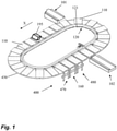
- FIG. 1 shows a weighing system 400 according to the invention.
- the weighing system 400 comprises a plurality of containers 110, the present example a tray 110, connected to a conveyor means 120.
- the conveyor means 120 comprises an array of concatenated conveyor bars 121 mutually hingedly connected to form an endless chain.
- the conveyor means also comprises an actuator 125 to power or drive the conveyor bars 120.
- Each conveyor bar 121 is connected to a tray 110, such that the tray 110 connected to it is conveyed in an horizontal position in a conveying direction defining an axis X, as shown by an arrow in Figure 1 .
- said trays 110 are also guided by a guide means 430 arranged in said weighing system 400.
- the tray 110 can be thus conveyed from a receiving section 101 to an outlet section 102 of the weighing system 400, and so does an item 195 being supported on top of a tray 110.
- the item 195 may be pushed by a pushing organ 198 arranged on the tray 110 at the outlet section 102 depending on its weight, as will be explained below.
- Figure 1 also shows that the weighing system 400 comprises a weighing device 160 arranged under the path of the trays 110, a location of which is suitable for collecting data relating to the weight of the item 195 being transported by one tray 110.
- FIG 2 shows a lateral side view of a section of the guiding means 430 before and after the weighing device 160.
- the weighing device 160 forms a weighing area 181 supported by a frame 183.
- the weighing area 181 is arranged for weighing the items 195 supported on top of the trays 110.
- two photoelectric cells 184 and 184' may be arranged to cooperate with the weighing device 160.
- the weighing device 160 is also in communication with a processing unit (not shown) connected to an actuator (not shown).
- the tray 110 Since the tray 110 is fixed to the conveyor bar when being conveyed in the first vertical position, said tray has to be moved upwardly from said fixed position to be weighed by the weighing device 160.
- the lifting device arranged upstream the weighing device 160 in the conveying direction. It comprises a receiving area 471 supported by a frame 473. In the conveying direction, the receiving area 471 defines a positive slope towards the weighing area 181, said receiving area 471 being thus adjacent to the weighing area 181.
- the weighing device 400 comprises guide rails 41, 42, 43 arranged for receiving the wheels 91, 92, 93 of the tray 110 depicted in figures 3 - 5 and for moving them upwardly such that said tray 110 is moved also upwardly with respect to the conveyor bar 121 to reach the unfixed position when being supported by the weighing area 181.
- the weight of the tray 110 supporting the item 195 is weighed by the weighing device 160 in the unfixed position, and the effect of the conveyor bar 121 on the load generated by the weight if said tray 110 and the item 195 on the weighing area 181 is negligible.
- the weighing system 400 also comprises a setting-down device 480 arranged downstream the weighing device 160 in the conveying direction.
- the setting-down device 480 comprises a frame 483 for supporting a setting-down area 481 arranged such that in the conveying direction X said setting-down area 481 defines a negative slope starting near the weighing area 181.
- the tray 110 arrives at the setting-down device 480 from the weighing device 160.
- rails 41, 42, 43 defining said setting-down area 481 guide the wheels 91, 92, 93 downwardly from the weighing device when said tray is being conveyed.
- a downward movement of the tray 110 with respect to the conveyor bar 121 is allowed due to gravity, said tray 110 reaching again the fixed position.
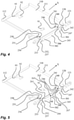
- Figure 3 shows a bottom side of the tray 110 relative to a conveyor bar 121 arranged in a conveyor chain of the conveyor means 120.
- the conveyor bar 121 capable of moving along the conveying direction transfers, in such operation, a driving load on the tray 110 via a primary connection means 240 and a secondary connection means 250.
- the primary connecting means 240 may face a front side 111 of the container 110 when seen in the conveying direction and the secondary connecting means 250 may face a rear side 112 of the container 110 when seen in the conveying direction.
- a distance extends between the primary connecting means 240 and the secondary connecting means 250. The distance is preferably as large as possible to achieve a high accurate measurement of a weight of the tray including an item on top of it.
- the tray 110 is connected to the conveyor means 120 via a primary connecting means 240 and a secondary connecting means 250.
- Each of the two connecting means comprises a first section 241, 251 permanently connected to the tray 110, a second section 242, 252 permanently connected to the conveyor means 120, and a third section 243, 253 hingedly connected to both the first section 241, 251 and the second section 242, 252.
- the primary third section 243 comprises a primary first pin 246 arranged within a primary first opening of the primary first section 241. The cooperation of the primary first pin 246 and the primary first opening allows for hingedly connection of said primary third section 243 with the primary first section 241. Similarly, said primary third section 243 is hingedly connected to the primary second section via a primary second pin 247 of said primary third section 243 and arranged within a primary second opening of said primary second section 242.
- the secondary third section 253 also comprises a secondary first pin 256 and a secondary second pin 257. In this way, the secondary third section 253 is hingedly connected to the secondary first section 251 via a secondary first opening arranged in said secondary first section 251 and to the secondary second section 252 via a secondary second opening arranged in said secondary second section 252.
- Both connecting means 240, 250 are arranged such that the third section 243 of the primary connecting means 240 and the third section 253 of the secondary connecting means 250 are rotatable about a first axis substantially parallel to the conveying direction.
- the rotation of said third sections 243, 253 about the first axis allows for movement of the tray 110 with respect to the conveyor means 120 in a vertical direction from the first vertical position to a second vertical position.
- the third section 243 of the primary connecting means 240 and the third section 253 of the secondary connecting means 250 are mutually coupled by means of a coupling element 300 arranged to interconnect the third section 243 of the primary connecting means 240 and the third section 253 of the secondary connecting means 250.
- the coupling element 300 is in this example a construction element which is torsionally rigid along an axis extending parallel to the conveying direction. This helps to reduce tilting of the container 110 (tray), thus improving the measurement.
- the coupling element 300 may be an elongated construction element such as a bar or a pipe.
- the coupling element 300 is having a first end 301 pointing forward in the conveying direction and a second end 302 pointing backward in the conveying direction.
- the first end 301 of the coupling element 300 is permanently connected to the third section 243 of the primary connecting means 240 and the second end 302 of the coupling element 300 is permanently connected to the third section 253of the secondary connecting means 250 so as the coupling element 300 to extend between the identical linkages 240, 250 and to span the distance between the third sections 243, 253.
- the first end 301 of the coupling element 300 is welded to the third section 243 of the primary connecting means 240 and the second end 302 of the coupling element 300 is welded to the third section 253 of the secondary connecting means 250.
- the tray 110 according to figure 3 is equipped with wheels such a first roller 91 fixed to the bottom of the container 110 at a position between the primary connecting means 240 and the secondary connecting means 250, preferably in the middle between the front side 111 of the container 110 when seen in the conveying direction and the rear side 112 of the container 110 when seen in the conveying direction.
- a third roller 93 is arranged at a side of the container 110 opposing the conveyor means 120, or, in other words, at a side of the tray 110 where the item to be conveyed leaves the tray 110 when it is being pushed away by the pushing organ 198.
- the third roller 93 is capable of running over a rail 43 or guiding means 430. Both the first and the third roller are preferably having the same diameter dimensions and have shafts of rotation which are collinear.
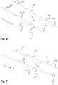
- the tray 110 according to figure 3 is capable of running over the weighing system 400 wherein the weighing area is equipped with a first guide rail 41 and a second guide rail 42 according to figure 6 so as to move the tray 110 between the first vertical position and the second vertical position according to a lifting or translation along the axis Z of the entire tray 110.
- the first and second guide rail 41, 42 are each having a slightly inclined positive slope 411, 421 in the receiving area 471 of the weighing system 400 and a slightly inclined negative slope 419,429 in the setting-down area 481 of the weighing system 400.
- the tray 110 according to figure 3 is capable of running over the weighing system 400 wherein the weighing area is equipped with a first guide rail 41 and a third guide rail 43 according to figure 7 so as to move the tray 110 between the first vertical position and the second vertical position according to a tilting along the axis X.
- the first guide rail 41 is having a slightly inclined positive slope 411 in the receiving area 471 of the weighing system 400 and a slightly inclined negative slope 419 in the setting-down area 481 of the weighing system 400.
- the third guide rail 430 does not have inclined positive or negative slopes at all and forms a one-off flat area to guide the third guide roller 93 of the tray 110 depicted in figure 3 .
- Figure 4 shows a bottom side of the tray 110 relative to a conveyor bar 121 arranged in a conveyor chain of the conveyor means 120 as well.
- the tray 110 according to figure 4 is equipped with a second roller 92 fixed to the bottom of the container 110, collinear with and between the first and the third roller 91, 93, however locating very near to the third roller 93.
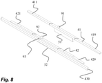
- the tray 110 according to figure 4 is capable of running over the weighing system 400 wherein the weighing area is equipped with a first guide rail 41, a second guide rail 42, and a third guide rail 430 according to figure 8 so as to move the tray 110 between the first vertical position and the second vertical position according to a lifting or translation along the axis Z of the entire tray 110.
- the first and second guide rail 41, 42 are each having a slightly inclined positive slope 411, 421 in the receiving area 471 of the weighing system 400 and a slightly inclined negative slope 419,429 in the setting-down area 481 of the weighing system 400.
- the third roller 93 of the tray 110 is, when it is in the second vertical position, moving over the third guide rail 430 without contacting it.
- the load of the tray 110 including the item can be measured by means of load cells 51, 52 supporting the tray 110 conveyed.
- the tray 110 according to figure 5 is capable of running over the weighing system 400 similar like the tray 110 depicted in figure 4 .
- the tray 110 according to figure 5 wherein the second roller would be omitted is capable of running over the weighing system 400 similar like the tray 110 depicted in figure 3 .
- the tray 110 according to figure 5 is basically similar to the tray 110 depicted in figure 4 but differs therewith in that the third section 243 of the primary connecting means 240 as well as the third section 253 of the secondary connecting means 250 are, seen in conveying direction, flexible so as to allow deformation along an axis parallel to the conveyance direction. I.e. both the primary connecting means 240 as well as the secondary connecting means 250 are unable to transfer a driving force from the conveyor means 120 without deformation of the third sections so that a load measured is influenced by interference.
- a tertiary connecting means 260 is arranged comprising a first section 261 permanently connected to the tray 110, a second section 262 permanently connected to the conveyor means 120, and a third section 263 hingedly connected to both the first section 261 and the second section 262 of the tertiary connecting means 260.
- the tertiary third section 263 comprises a tertiary first pin 266 arranged within a tertiary first opening of the tertiary first section 261.
- the cooperation of the tertiary first pin 266 and the tertiary first opening allows for hingedly connection of said tertiary third section 263 with the tertiary first section 261.
- said tertiary third section 263 is hingedly connected to the tertiary second section 262 via a tertiary second pin 267 of said tertiary third section 263 and arranged within a tertiary second opening of said tertiary second section 262.
- the tertiary connecting means 260 is arranged such that the third section 263 of the tertiary connecting means 260 is rotatable about a second axis transverse to the conveying direction such that the rotation of said third section 263 about the second axis allows for movement of the tray 110 with respect to the conveyor means 120 in a vertical direction from the first vertical position to a second vertical position.
- the weighing system 400 achieves a high accuracy measurement of the weight of the tray 110 including the item supported by the tray 110.
- the weighing system 400 allows measurement of the weight during conveyance.
- the first guide rail 41 has a slightly inclined positive slope 411 in the receiving area 471 of the weighing system 400 and a slightly inclined negative slope 419 in the setting-down area 481 of the weighing system 400, the tray 110 is slightly tilted about the axis along the conveying direction, resulting is a small angled position of the item.
- the tray 110 remains level or flush with the horizontal, so that the position of the item is not affected at all.
Landscapes
- Physics & Mathematics (AREA)
- General Physics & Mathematics (AREA)
- Engineering & Computer Science (AREA)
- Mechanical Engineering (AREA)
- Weight Measurement For Supplying Or Discharging Of Specified Amounts Of Material (AREA)
Claims (14)
- Wiegesystem (400) zum Wiegen eines Gegenstandes (195), wenn er von einem Aufnahmeabschnitt (101) zu einem Ausgabeabschnitt (102) befördert wird, wobei das Wiegesystem (400) umfasst:- mindestens einen Behälter (110) zum Transportieren des Gegenstandes (195);- ein Fördermittel (120), das mit dem Behälter (110) verbunden ist, um den Behälter (110) in einer Förderrichtung in einer ersten vertikalen Position relativ zu dem Fördermittel (120) zu fördern; und- eine Wiegevorrichtung (160) zum Wiegen des Behälters (110), wenn der Behälter (110) über die Wiegevorrichtung (160) befördert und von dieser getragen wird;wobei der Behälter (110) mit dem Fördermittel (120) über ein primäres Verbindungsmittel (240) und ein sekundäres Verbindungsmittel (250) verbunden ist, wobei jedes der beiden Verbindungsmittel einen ersten Abschnitt (241, 251), der permanent mit dem Behälter (110) verbunden ist, einen zweiten Abschnitt (242, 252), der permanent mit dem Fördermittel verbunden ist, und einen dritten Abschnitt (243, 253), der sowohl mit dem ersten Abschnitt (241, 251) als auch mit dem zweiten Abschnitt (242, 252) gelenkig verbunden ist, umfasst;wobei beide Verbindungsmittel so angeordnet sind, dass der dritte Abschnitt (243) des primären Verbindungsmittels (240) und der dritte Abschnitt (253) des sekundären Verbindungsmittels (250) um eine erste Achse drehbar sind, die im Wesentlichen parallel zur Förderrichtung verläuft, so dass die Drehung der dritten Abschnitte (243, 253) um die erste Achse eine Bewegung des Behälters (110) in Bezug auf das Fördermittel (120) in einer vertikalen Richtung von der ersten vertikalen Position zu einer zweiten vertikalen Position ermöglicht, undwobei der dritte Abschnitt (243) des primären Verbindungsmittels (240) und der dritte Abschnitt (253) des sekundären Verbindungsmittels (250) miteinander gekoppelt sind,der Behälter (110) ist, zusätzlich, mit dem Fördermittel (120) über ein tertiäres Verbindungsmittel (260) verbunden, das einen ersten Abschnitt (261), der permanent mit dem Behälter (110) verbunden ist, einen zweiten Abschnitt (262), der permanent mit dem Fördermittel (120) verbunden ist, und einen dritten Abschnitt (263) umfasst, der sowohl mit dem ersten Abschnitt (261) als auch mit dem zweiten Abschnitt (262) des tertiären Verbindungsmittels (260) gelenkig verbunden ist; wobei das tertiäre Verbindungsmittel (260) so angeordnet ist, dass der dritte Abschnitt (263) des tertiären Verbindungsmittels (260) um eine zweite Achse quer zur Förderrichtung drehbar ist, so dass die Drehung des dritten Abschnitts (263) um die zweite Achse eine Bewegung des Behälters (110) in Bezug auf das Fördermittel (120) in einer vertikalen Richtung von der ersten vertikalen Position zu einer zweiten vertikalen Position ermöglicht.
- Wiegesystem (400) nach Anspruch 1, wobei das primäre Verbindungsmittel (240) und das sekundäre Verbindungsmittel (250) identische Verbindungsglieder (240, 250) bilden, die in einem Abstand voneinander angeordnet sind, so dass sie an den Behälter (110) zwischen der Vorderseite und der Rückseite desselben passen, wenn man die Förderrichtung betrachtet.
- Wiegesystem (400) nach Anspruch 1 oder 2, wobei ein Kupplungselement (300) angeordnet ist, um den dritten Abschnitt (243) des primären Verbindungsmittels (240) und den dritten Abschnitt (253) des sekundären Verbindungsmittels (250) miteinander zu verbinden.
- Wiegesystem (400) nach Anspruch 3, wobei das Kupplungselement (300) ein Konstruktionselement ist, das entlang einer parallel zur Förderrichtung verlaufenden Achse verwindungssteif ist.
- Wiegesystem (400) nach Anspruch 3 oder 4, wobei das Kupplungselement (300) ein langgestrecktes Konstruktionselement, wie beispielsweise eine Stange oder ein Rohr, ist.
- Wiegesystem (400) nach Anspruch 3, 4 oder 5, wobei das Kupplungselement (300) ein erstes Ende (301), das in Förderrichtung nach vorne weist, und ein zweites Ende (302), das in Förderrichtung nach hinten weist, aufweist, wobei dessen erstes Ende (301) permanent mit dem dritten Abschnitt (243) des primären Verbindungsmittels (240) verbunden ist und dessen zweites Ende (302) permanent mit dem dritten Abschnitt (253) des sekundären Verbindungsmittels (250) verbunden ist, so dass sich das Kupplungselement (300) zwischen den gleichen Verbindungsgliedern (240, 250) erstreckt und den Abstand zwischen den dritten Abschnitten (243, 253) überbrückt.
- Wiegesystem (400) nach Anspruch 6, wobei das erste Ende (301) des Kupplungselements (300) mit dem dritten Abschnitt (243) des primären Verbindungsmittels (240) verschweißt ist und das zweite Ende (302) des Kupplungselements (300) mit dem dritten Abschnitt (253) des sekundären Verbindungsmittels (250) verschweißt ist.
- Wiegesystem (400) nach einem der vorhergehenden Ansprüche, wobei der dritte Abschnitt (243) des primären Verbindungsmittels (240) sowie der dritte Abschnitt (253) des sekundären Verbindungsmittels (250) so ausgebildet sind, dass sie eine Bewegung des Behälters (110) zwischen der ersten vertikalen Position und der zweiten vertikalen Position ermöglichen und die Betätigung des Fördermittels (120) auf den Behälter (110) in Förderrichtung übertragen.
- Wiegesystem (400) nach einem der vorhergehenden Ansprüche, wobei der dritte Abschnitt (243) des primären Verbindungsmittels (240) sowie der dritte Abschnitt (253) des sekundären Verbindungsmittels (250) in Förderrichtung gesehen flexibel sind, um eine Verformung entlang einer Achse parallel zur Förderrichtung zu ermöglichen.
- Wiegesystem (400) nach einem der vorhergehenden Ansprüche, wobei eine Hebevorrichtung (470) angeordnet ist, die einen Rahmen (473) umfasst, wobei der Rahmen (473) einen Aufnahmebereich (471) neben der Wiegevorrichtung (160) umfasst, wobei der Aufnahmebereich (471) konfiguriert ist, wenn der Behälter (110) befördert wird, zumiii) Aufnehmen des Behälters (110) in der ersten vertikalen Position und;iv) Führen des Behälters (110) nach oben in die zweite vertikale Position mittels einer ersten Führungsschiene (41), auf die eine erste Rolle (91) auftrifft, die am Boden des Behälters (110) an einer Position zwischen dem primären Verbindungsmittel (240) und dem sekundären Verbindungsmittel (250) befestigt ist, vorzugsweise in der Mitte zwischen der Vorderseite des Behälters (110) in Förderrichtung gesehen und der Rückseite des Behälters (110) in Förderrichtung gesehen.
- Wiegesystem (400) nach Anspruch 10, wobei der Aufnahmebereich (471) weiter konfiguriert ist, wenn der Behälter (110) befördert wird, zum Führen des Behälters (110) zur Aufwärtsverschiebung in Richtung der zweiten vertikalen Position mittels einer zweiten Führungsschiene (42), auf die eine zweite Rolle (92) auftrifft, die am Boden des Behälters (110) an einer von dem Fördermittel (120) abgewandten Position befestigt ist, vorzugsweise in der Mitte zwischen der Vorderseite des Behälters (110) in Förderrichtung gesehen und der Rückseite des Behälters (110) in Förderrichtung gesehen.
- Wiegesystem (400) nach Anspruch 11, wobei der Aufnahmebereich (471) weiter konfiguriert ist, wenn der Behälter (110) befördert wird, zum Führen des Behälters (110) zum Aufwärtskippen entlang einer zur Förderrichtung parallelen Achse, wobei das Kippen mittels einer dritten Führungsschiene (43) bewirkt wird, die mit einer Schiene (430) bündig und fluchtend ist, bevor der Behälter in den Aufnahmebereich eintritt, wobei der dritten Führungsschiene (43) eine dritte Rolle (93) folgt, die am Boden des Behälters (110) an einer dem Fördermittel (120) abgewandten Position befestigt ist, vorzugsweise in der Mitte zwischen der Vorderseite des Behälters (110) in Förderrichtung gesehen und der Rückseite des Behälters (110) in Förderrichtung gesehen.
- Wiegesystem (400) nach Anspruch 10, 11 oder 12, wobei das Wiegesystem (400) weiter eine Absetzvorrichtung (480) umfasst, die benachbart zu der Wiegevorrichtung (160) angeordnet ist, wobei die Absetzvorrichtung (480) einen Rahmen (483) umfasst, wobei der Rahmen (483) einen Absetzbereich (481) umfasst, der konfiguriert ist, wenn der Behälter (110) durch das Fördermittel (120) befördert wird, zumi) Aufnehmen des Behälters (110) in der zweiten vertikalen Position von der Wiegevorrichtung (160) und;ii) Führen des Behälters (110) aus der zweiten vertikalen Position in Richtung der ersten vertikalen Position.
- Wiegesystem (400) nach einem der vorhergehenden Ansprüche, wobei der Behälter (110) mit Rädern (91, 92) zum Bewegen des Behälters (110) über die Wiegevorrichtung (160) und zum Anheben des Behälters (110) von der ersten vertikalen Position in die zweite vertikale Position versehen ist.
Applications Claiming Priority (1)
| Application Number | Priority Date | Filing Date | Title |
|---|---|---|---|
| NL2020297A NL2020297B1 (en) | 2018-01-18 | 2018-01-18 | A weighing system |
Publications (2)
| Publication Number | Publication Date |
|---|---|
| EP3514510A1 EP3514510A1 (de) | 2019-07-24 |
| EP3514510B1 true EP3514510B1 (de) | 2022-03-09 |
Family
ID=65041606
Family Applications (1)
| Application Number | Title | Priority Date | Filing Date |
|---|---|---|---|
| EP19152458.6A Active EP3514510B1 (de) | 2018-01-18 | 2019-01-18 | Wägesystem |
Country Status (3)
| Country | Link |
|---|---|
| US (1) | US11002590B2 (de) |
| EP (1) | EP3514510B1 (de) |
| NL (1) | NL2020297B1 (de) |
Families Citing this family (2)
| Publication number | Priority date | Publication date | Assignee | Title |
|---|---|---|---|---|
| NL2017181B1 (en) * | 2016-07-18 | 2018-01-24 | Optimus Sorter Holding B V | A weighing system |
| DE102017001226B4 (de) * | 2017-02-09 | 2019-04-18 | Schenck Process Europe Gmbh | Förder- und Dosiervorrichtung |
Family Cites Families (22)
| Publication number | Priority date | Publication date | Assignee | Title |
|---|---|---|---|---|
| US1404591A (en) | 1920-03-13 | 1922-01-24 | Fredrickson Christian | Conveying apparatus |
| US2625830A (en) * | 1950-09-20 | 1953-01-20 | Sherman T Transeau | Attachment link for sprocket chains |
| US3454614A (en) | 1965-03-29 | 1969-07-08 | Chiyoda Chem Eng Construct Co | Methods of manufacturing alkali dialkylaluminates |
| US3918587A (en) | 1973-11-16 | 1975-11-11 | Gainesville Machine Company In | Apparatus for detecting and dispensing articles of preselected weights suspended from shackles |
| US4187945A (en) | 1978-06-29 | 1980-02-12 | W. F. Altenpohl, Inc. | Plural path weight sorting system |
| US4957619A (en) * | 1988-09-23 | 1990-09-18 | Powell Machinery, Inc. | Self-singulating weight sizer |
| NL9101821A (nl) * | 1991-10-30 | 1993-05-17 | Tas Adrianus Wilhelmus | Werkwijze en inrichting voor het op gewicht sorteren van in hoofdzaak ronde produkten. |
| IT1294114B1 (it) | 1997-01-23 | 1999-03-22 | Unitec Srl | Impianto perfezionato di trasporto e di pesatura automatica di prodotti singoli, in particolare vegetali |
| ES2153749B1 (es) | 1998-08-25 | 2003-08-16 | Olaechea Rosalina Paniagua | Maquina pesadora automatica de frutas y similares. |
| IT1320925B1 (it) * | 2000-03-17 | 2003-12-10 | Ima Spa | Unita' per l'alimentazione di contenitori lungo una linea di trasportoe per il trasferimento dei contenitori medesimi da e verso una |
| FR2849790B1 (fr) * | 2003-01-09 | 2005-05-20 | Michel Durand | Dispositif de convoyage de produits, notamment de fruits ou legumes, adapte pour effectuer un triage des produits au moins en fonction de leur poids |
| JP4182475B2 (ja) * | 2003-05-12 | 2008-11-19 | 株式会社ダイフク | 昇降荷台付き搬送装置 |
| DE50302083D1 (de) * | 2003-10-29 | 2006-02-02 | Hinterkopf Gmbh | Transporteinrichtung für Hohlkörper |
| FR2887180B1 (fr) | 2005-06-15 | 2007-08-17 | Sagem Comm | Consommable avec bobineaux solidarisables entre eux pour dispositif d'impression |
| JP4189685B2 (ja) * | 2005-08-04 | 2008-12-03 | 株式会社ダイフク | 台車式搬送装置 |
| CA2657203C (en) * | 2007-01-30 | 2011-07-12 | Daifuku Co., Ltd. | Conveyance device using carriage |
| NL1033567C2 (nl) | 2007-03-20 | 2008-09-23 | Lwf Holding B V | Transportsysteem. |
| NL2012822B1 (nl) | 2014-05-15 | 2016-03-02 | Optimus Sorter Holding B V | Sorteerinrichting. |
| NL2013604B1 (nl) | 2014-10-09 | 2016-10-04 | Optimus Sorter Holding B V | Inrichting voor het laden, transporteren en lossen van voorwerpen. |
| NL2014325B1 (en) | 2015-02-20 | 2016-10-13 | Optimus Sorter Holding B V | A conveyor system comprising a plurality of support members and a method thereof. |
| FR3035087B1 (fr) * | 2015-04-17 | 2017-04-21 | Maf Agrobotic | Dispositif de transport d'objets et dispositif de convoyage et de pesee equipe de tels dispositifs de transport |
| NL2017181B1 (en) * | 2016-07-18 | 2018-01-24 | Optimus Sorter Holding B V | A weighing system |
-
2018
- 2018-01-18 NL NL2020297A patent/NL2020297B1/en not_active IP Right Cessation
-
2019
- 2019-01-18 US US16/252,272 patent/US11002590B2/en active Active
- 2019-01-18 EP EP19152458.6A patent/EP3514510B1/de active Active
Also Published As
| Publication number | Publication date |
|---|---|
| US11002590B2 (en) | 2021-05-11 |
| NL2020297B1 (en) | 2019-07-29 |
| US20190219439A1 (en) | 2019-07-18 |
| EP3514510A1 (de) | 2019-07-24 |
Similar Documents
| Publication | Publication Date | Title |
|---|---|---|
| CN102015493B (zh) | 用于产品输送的装置 | |
| US11002590B2 (en) | Weighing system | |
| US8237067B2 (en) | Checkweigher with independent scales | |
| EA005328B1 (ru) | Цепной транспортёр в виде весов | |
| EP3059561B1 (de) | Fördersystem mit einer vielzahl an stützelementen und verfahren dafür | |
| US10239741B2 (en) | Suspension-type stacker crane | |
| US6452118B1 (en) | Weighing apparatus | |
| US11440742B2 (en) | Conveying and metering device | |
| EP3485241B1 (de) | Wägesystem | |
| EP0108445B1 (de) | Einrichtung zur Gewichtsklassierung von Feldfrüchten | |
| CN102673967B (zh) | 用于传输至少一个物体的垫子、传送装置和传送方法 | |
| CN218424212U (zh) | 一种分拣设备 | |
| KR102501152B1 (ko) | 무게측정장치를 포함하는 스케일 컨베이어 및 이를 포함하는 체크인 컨베이어 | |
| JP4480532B2 (ja) | 農作物の計量選別装置 | |
| KR101097936B1 (ko) | 패널배출시스템 | |
| FI58761C (fi) | Nedfaellningsanordning foer stockar till sorteringstransportoerer foer desamma | |
| EP0459555B1 (de) | Ladeeinrichtung für dynamische Wiegemaschinen | |
| GB2110393A (en) | Conveying apparatus | |
| CN111054643A (zh) | 货物分拣装置 | |
| CN216606180U (zh) | 一种新型动态双重称重分拣设备 | |
| SU781123A1 (ru) | Конвейер дл вертикального перемещени грузов | |
| SU1548670A1 (ru) | Автоматические конвейерные весы | |
| IT8223512A1 (it) | Alimentatore a catena | |
| JPS62269805A (ja) | 垂直コンベヤ用のベルト式バケツトエレベ−タ |
Legal Events
| Date | Code | Title | Description |
|---|---|---|---|
| PUAI | Public reference made under article 153(3) epc to a published international application that has entered the european phase |
Free format text: ORIGINAL CODE: 0009012 |
|
| STAA | Information on the status of an ep patent application or granted ep patent |
Free format text: STATUS: THE APPLICATION HAS BEEN PUBLISHED |
|
| AK | Designated contracting states |
Kind code of ref document: A1 Designated state(s): AL AT BE BG CH CY CZ DE DK EE ES FI FR GB GR HR HU IE IS IT LI LT LU LV MC MK MT NL NO PL PT RO RS SE SI SK SM TR |
|
| AX | Request for extension of the european patent |
Extension state: BA ME |
|
| STAA | Information on the status of an ep patent application or granted ep patent |
Free format text: STATUS: REQUEST FOR EXAMINATION WAS MADE |
|
| 17P | Request for examination filed |
Effective date: 20200117 |
|
| RBV | Designated contracting states (corrected) |
Designated state(s): AL AT BE BG CH CY CZ DE DK EE ES FI FR GB GR HR HU IE IS IT LI LT LU LV MC MK MT NL NO PL PT RO RS SE SI SK SM TR |
|
| GRAP | Despatch of communication of intention to grant a patent |
Free format text: ORIGINAL CODE: EPIDOSNIGR1 |
|
| STAA | Information on the status of an ep patent application or granted ep patent |
Free format text: STATUS: GRANT OF PATENT IS INTENDED |
|
| INTG | Intention to grant announced |
Effective date: 20210624 |
|
| GRAJ | Information related to disapproval of communication of intention to grant by the applicant or resumption of examination proceedings by the epo deleted |
Free format text: ORIGINAL CODE: EPIDOSDIGR1 |
|
| STAA | Information on the status of an ep patent application or granted ep patent |
Free format text: STATUS: REQUEST FOR EXAMINATION WAS MADE |
|
| GRAS | Grant fee paid |
Free format text: ORIGINAL CODE: EPIDOSNIGR3 |
|
| STAA | Information on the status of an ep patent application or granted ep patent |
Free format text: STATUS: GRANT OF PATENT IS INTENDED |
|
| GRAP | Despatch of communication of intention to grant a patent |
Free format text: ORIGINAL CODE: EPIDOSNIGR1 |
|
| INTC | Intention to grant announced (deleted) | ||
| INTG | Intention to grant announced |
Effective date: 20211108 |
|
| GRAF | Information related to payment of grant fee modified |
Free format text: ORIGINAL CODE: EPIDOSCIGR3 |
|
| GRAA | (expected) grant |
Free format text: ORIGINAL CODE: 0009210 |
|
| STAA | Information on the status of an ep patent application or granted ep patent |
Free format text: STATUS: THE PATENT HAS BEEN GRANTED |
|
| AK | Designated contracting states |
Kind code of ref document: B1 Designated state(s): AL AT BE BG CH CY CZ DE DK EE ES FI FR GB GR HR HU IE IS IT LI LT LU LV MC MK MT NL NO PL PT RO RS SE SI SK SM TR |
|
| REG | Reference to a national code |
Ref country code: CH Ref legal event code: EP Ref country code: AT Ref legal event code: REF Ref document number: 1474533 Country of ref document: AT Kind code of ref document: T Effective date: 20220315 |
|
| REG | Reference to a national code |
Ref country code: DE Ref legal event code: R096 Ref document number: 602019012248 Country of ref document: DE |
|
| REG | Reference to a national code |
Ref country code: IE Ref legal event code: FG4D |
|
| REG | Reference to a national code |
Ref country code: NL Ref legal event code: PD Owner name: BOEWE SYSTEC GMBH; DE Free format text: DETAILS ASSIGNMENT: CHANGE OF OWNER(S), ASSIGNMENT; FORMER OWNER NAME: OPTIMUS SORTER HOLDING B.V. Effective date: 20220601 Ref country code: NL Ref legal event code: FP |
|
| REG | Reference to a national code |
Ref country code: LT Ref legal event code: MG9D |
|
| RAP2 | Party data changed (patent owner data changed or rights of a patent transferred) |
Owner name: BOEWE SYSTEC GMBH |
|
| PG25 | Lapsed in a contracting state [announced via postgrant information from national office to epo] |
Ref country code: SE Free format text: LAPSE BECAUSE OF FAILURE TO SUBMIT A TRANSLATION OF THE DESCRIPTION OR TO PAY THE FEE WITHIN THE PRESCRIBED TIME-LIMIT Effective date: 20220309 Ref country code: RS Free format text: LAPSE BECAUSE OF FAILURE TO SUBMIT A TRANSLATION OF THE DESCRIPTION OR TO PAY THE FEE WITHIN THE PRESCRIBED TIME-LIMIT Effective date: 20220309 Ref country code: NO Free format text: LAPSE BECAUSE OF FAILURE TO SUBMIT A TRANSLATION OF THE DESCRIPTION OR TO PAY THE FEE WITHIN THE PRESCRIBED TIME-LIMIT Effective date: 20220609 Ref country code: LT Free format text: LAPSE BECAUSE OF FAILURE TO SUBMIT A TRANSLATION OF THE DESCRIPTION OR TO PAY THE FEE WITHIN THE PRESCRIBED TIME-LIMIT Effective date: 20220309 Ref country code: HR Free format text: LAPSE BECAUSE OF FAILURE TO SUBMIT A TRANSLATION OF THE DESCRIPTION OR TO PAY THE FEE WITHIN THE PRESCRIBED TIME-LIMIT Effective date: 20220309 Ref country code: BG Free format text: LAPSE BECAUSE OF FAILURE TO SUBMIT A TRANSLATION OF THE DESCRIPTION OR TO PAY THE FEE WITHIN THE PRESCRIBED TIME-LIMIT Effective date: 20220609 |
|
| REG | Reference to a national code |
Ref country code: AT Ref legal event code: MK05 Ref document number: 1474533 Country of ref document: AT Kind code of ref document: T Effective date: 20220309 |
|
| PG25 | Lapsed in a contracting state [announced via postgrant information from national office to epo] |
Ref country code: LV Free format text: LAPSE BECAUSE OF FAILURE TO SUBMIT A TRANSLATION OF THE DESCRIPTION OR TO PAY THE FEE WITHIN THE PRESCRIBED TIME-LIMIT Effective date: 20220309 Ref country code: GR Free format text: LAPSE BECAUSE OF FAILURE TO SUBMIT A TRANSLATION OF THE DESCRIPTION OR TO PAY THE FEE WITHIN THE PRESCRIBED TIME-LIMIT Effective date: 20220610 Ref country code: FI Free format text: LAPSE BECAUSE OF FAILURE TO SUBMIT A TRANSLATION OF THE DESCRIPTION OR TO PAY THE FEE WITHIN THE PRESCRIBED TIME-LIMIT Effective date: 20220309 |
|
| PG25 | Lapsed in a contracting state [announced via postgrant information from national office to epo] |
Ref country code: SM Free format text: LAPSE BECAUSE OF FAILURE TO SUBMIT A TRANSLATION OF THE DESCRIPTION OR TO PAY THE FEE WITHIN THE PRESCRIBED TIME-LIMIT Effective date: 20220309 Ref country code: SK Free format text: LAPSE BECAUSE OF FAILURE TO SUBMIT A TRANSLATION OF THE DESCRIPTION OR TO PAY THE FEE WITHIN THE PRESCRIBED TIME-LIMIT Effective date: 20220309 Ref country code: RO Free format text: LAPSE BECAUSE OF FAILURE TO SUBMIT A TRANSLATION OF THE DESCRIPTION OR TO PAY THE FEE WITHIN THE PRESCRIBED TIME-LIMIT Effective date: 20220309 Ref country code: PT Free format text: LAPSE BECAUSE OF FAILURE TO SUBMIT A TRANSLATION OF THE DESCRIPTION OR TO PAY THE FEE WITHIN THE PRESCRIBED TIME-LIMIT Effective date: 20220711 Ref country code: ES Free format text: LAPSE BECAUSE OF FAILURE TO SUBMIT A TRANSLATION OF THE DESCRIPTION OR TO PAY THE FEE WITHIN THE PRESCRIBED TIME-LIMIT Effective date: 20220309 Ref country code: EE Free format text: LAPSE BECAUSE OF FAILURE TO SUBMIT A TRANSLATION OF THE DESCRIPTION OR TO PAY THE FEE WITHIN THE PRESCRIBED TIME-LIMIT Effective date: 20220309 Ref country code: CZ Free format text: LAPSE BECAUSE OF FAILURE TO SUBMIT A TRANSLATION OF THE DESCRIPTION OR TO PAY THE FEE WITHIN THE PRESCRIBED TIME-LIMIT Effective date: 20220309 Ref country code: AT Free format text: LAPSE BECAUSE OF FAILURE TO SUBMIT A TRANSLATION OF THE DESCRIPTION OR TO PAY THE FEE WITHIN THE PRESCRIBED TIME-LIMIT Effective date: 20220309 |
|
| PG25 | Lapsed in a contracting state [announced via postgrant information from national office to epo] |
Ref country code: PL Free format text: LAPSE BECAUSE OF FAILURE TO SUBMIT A TRANSLATION OF THE DESCRIPTION OR TO PAY THE FEE WITHIN THE PRESCRIBED TIME-LIMIT Effective date: 20220309 Ref country code: IS Free format text: LAPSE BECAUSE OF FAILURE TO SUBMIT A TRANSLATION OF THE DESCRIPTION OR TO PAY THE FEE WITHIN THE PRESCRIBED TIME-LIMIT Effective date: 20220709 Ref country code: AL Free format text: LAPSE BECAUSE OF FAILURE TO SUBMIT A TRANSLATION OF THE DESCRIPTION OR TO PAY THE FEE WITHIN THE PRESCRIBED TIME-LIMIT Effective date: 20220309 |
|
| REG | Reference to a national code |
Ref country code: DE Ref legal event code: R097 Ref document number: 602019012248 Country of ref document: DE |
|
| PLBE | No opposition filed within time limit |
Free format text: ORIGINAL CODE: 0009261 |
|
| STAA | Information on the status of an ep patent application or granted ep patent |
Free format text: STATUS: NO OPPOSITION FILED WITHIN TIME LIMIT |
|
| PG25 | Lapsed in a contracting state [announced via postgrant information from national office to epo] |
Ref country code: DK Free format text: LAPSE BECAUSE OF FAILURE TO SUBMIT A TRANSLATION OF THE DESCRIPTION OR TO PAY THE FEE WITHIN THE PRESCRIBED TIME-LIMIT Effective date: 20220309 |
|
| 26N | No opposition filed |
Effective date: 20221212 |
|
| PG25 | Lapsed in a contracting state [announced via postgrant information from national office to epo] |
Ref country code: SI Free format text: LAPSE BECAUSE OF FAILURE TO SUBMIT A TRANSLATION OF THE DESCRIPTION OR TO PAY THE FEE WITHIN THE PRESCRIBED TIME-LIMIT Effective date: 20220309 |
|
| P01 | Opt-out of the competence of the unified patent court (upc) registered |
Effective date: 20230308 |
|
| PG25 | Lapsed in a contracting state [announced via postgrant information from national office to epo] |
Ref country code: IT Free format text: LAPSE BECAUSE OF FAILURE TO SUBMIT A TRANSLATION OF THE DESCRIPTION OR TO PAY THE FEE WITHIN THE PRESCRIBED TIME-LIMIT Effective date: 20220309 |
|
| REG | Reference to a national code |
Ref country code: CH Ref legal event code: PL |
|
| GBPC | Gb: european patent ceased through non-payment of renewal fee |
Effective date: 20230118 |
|
| PG25 | Lapsed in a contracting state [announced via postgrant information from national office to epo] |
Ref country code: LU Free format text: LAPSE BECAUSE OF NON-PAYMENT OF DUE FEES Effective date: 20230118 |
|
| REG | Reference to a national code |
Ref country code: BE Ref legal event code: MM Effective date: 20230131 |
|
| PG25 | Lapsed in a contracting state [announced via postgrant information from national office to epo] |
Ref country code: LI Free format text: LAPSE BECAUSE OF NON-PAYMENT OF DUE FEES Effective date: 20230131 Ref country code: GB Free format text: LAPSE BECAUSE OF NON-PAYMENT OF DUE FEES Effective date: 20230118 Ref country code: CH Free format text: LAPSE BECAUSE OF NON-PAYMENT OF DUE FEES Effective date: 20230131 |
|
| PG25 | Lapsed in a contracting state [announced via postgrant information from national office to epo] |
Ref country code: FR Free format text: LAPSE BECAUSE OF NON-PAYMENT OF DUE FEES Effective date: 20230131 Ref country code: BE Free format text: LAPSE BECAUSE OF NON-PAYMENT OF DUE FEES Effective date: 20230131 |
|
| PG25 | Lapsed in a contracting state [announced via postgrant information from national office to epo] |
Ref country code: IE Free format text: LAPSE BECAUSE OF NON-PAYMENT OF DUE FEES Effective date: 20230118 |
|
| PG25 | Lapsed in a contracting state [announced via postgrant information from national office to epo] |
Ref country code: MC Free format text: LAPSE BECAUSE OF FAILURE TO SUBMIT A TRANSLATION OF THE DESCRIPTION OR TO PAY THE FEE WITHIN THE PRESCRIBED TIME-LIMIT Effective date: 20220309 |
|
| PG25 | Lapsed in a contracting state [announced via postgrant information from national office to epo] |
Ref country code: MC Free format text: LAPSE BECAUSE OF FAILURE TO SUBMIT A TRANSLATION OF THE DESCRIPTION OR TO PAY THE FEE WITHIN THE PRESCRIBED TIME-LIMIT Effective date: 20220309 |
|
| PG25 | Lapsed in a contracting state [announced via postgrant information from national office to epo] |
Ref country code: CY Free format text: LAPSE BECAUSE OF FAILURE TO SUBMIT A TRANSLATION OF THE DESCRIPTION OR TO PAY THE FEE WITHIN THE PRESCRIBED TIME-LIMIT; INVALID AB INITIO Effective date: 20190118 |
|
| PG25 | Lapsed in a contracting state [announced via postgrant information from national office to epo] |
Ref country code: HU Free format text: LAPSE BECAUSE OF FAILURE TO SUBMIT A TRANSLATION OF THE DESCRIPTION OR TO PAY THE FEE WITHIN THE PRESCRIBED TIME-LIMIT; INVALID AB INITIO Effective date: 20190118 |
|
| PG25 | Lapsed in a contracting state [announced via postgrant information from national office to epo] |
Ref country code: TR Free format text: LAPSE BECAUSE OF FAILURE TO SUBMIT A TRANSLATION OF THE DESCRIPTION OR TO PAY THE FEE WITHIN THE PRESCRIBED TIME-LIMIT Effective date: 20220309 |
|
| PGFP | Annual fee paid to national office [announced via postgrant information from national office to epo] |
Ref country code: NL Payment date: 20260121 Year of fee payment: 8 |
|
| PGFP | Annual fee paid to national office [announced via postgrant information from national office to epo] |
Ref country code: DE Payment date: 20260121 Year of fee payment: 8 |