EP3485241B1 - Wägesystem - Google Patents
Wägesystem Download PDFInfo
- Publication number
- EP3485241B1 EP3485241B1 EP17757907.5A EP17757907A EP3485241B1 EP 3485241 B1 EP3485241 B1 EP 3485241B1 EP 17757907 A EP17757907 A EP 17757907A EP 3485241 B1 EP3485241 B1 EP 3485241B1
- Authority
- EP
- European Patent Office
- Prior art keywords
- section
- container
- connecting means
- vertical position
- weighing
- Prior art date
- Legal status (The legal status is an assumption and is not a legal conclusion. Google has not performed a legal analysis and makes no representation as to the accuracy of the status listed.)
- Active
Links
Images



Classifications
-
- G—PHYSICS
- G01—MEASURING; TESTING
- G01G—WEIGHING
- G01G11/00—Apparatus for weighing a continuous stream of material during flow; Conveyor belt weighers
-
- B—PERFORMING OPERATIONS; TRANSPORTING
- B07—SEPARATING SOLIDS FROM SOLIDS; SORTING
- B07C—POSTAL SORTING; SORTING INDIVIDUAL ARTICLES, OR BULK MATERIAL FIT TO BE SORTED PIECE-MEAL, e.g. BY PICKING
- B07C5/00—Sorting according to a characteristic or feature of the articles or material being sorted, e.g. by control effected by devices which detect or measure such characteristic or feature; Sorting by manually actuated devices, e.g. switches
- B07C5/16—Sorting according to weight
- B07C5/18—Sorting according to weight using a single stationary weighing mechanism
-
- B—PERFORMING OPERATIONS; TRANSPORTING
- B65—CONVEYING; PACKING; STORING; HANDLING THIN OR FILAMENTARY MATERIAL
- B65G—TRANSPORT OR STORAGE DEVICES, e.g. CONVEYORS FOR LOADING OR TIPPING, SHOP CONVEYOR SYSTEMS OR PNEUMATIC TUBE CONVEYORS
- B65G17/00—Conveyors having an endless traction element, e.g. a chain, transmitting movement to a continuous or substantially-continuous load-carrying surface or to a series of individual load-carriers; Endless-chain conveyors in which the chains form the load-carrying surface
- B65G17/30—Details; Auxiliary devices
- B65G17/32—Individual load-carriers
-
- G—PHYSICS
- G01—MEASURING; TESTING
- G01G—WEIGHING
- G01G11/00—Apparatus for weighing a continuous stream of material during flow; Conveyor belt weighers
- G01G11/003—Details; specially adapted accessories
-
- G—PHYSICS
- G01—MEASURING; TESTING
- G01G—WEIGHING
- G01G21/00—Details of weighing apparatus
- G01G21/23—Support or suspension of weighing platforms
Definitions
- the invention is in the field of weighing systems for weighing an item when being conveyed from a receiving section to an outlet section.
- EP0568763 discloses a weighing system comprising a plurality of containers arranged for transporting the item.
- Another relevant prior art document is US 3 918 587 .
- the containers are connected to a conveyor means arranged in the weighing system for conveying the containers in a conveying direction.
- the container is supported by the conveyor means in a first vertical position via a pin of the tray arranged in an recess of the conveyor means.
- the tray may be lifted to a second vertical position by further means, the lifting being guided by a movement of the pin along the opening defined by the recess.
- said tray is supported by a weighing device to weigh the container comprising the item.
- a problem of the above mentioned weighing system is that the tray is subjected to vibrations and/or movements when being conveyed in the second vertical position that may decrease the accuracy of the weighing process. It is an object of the present application to alleviate this problem.
- a first aspect of the invention relates to a weighing system for weighing an item when being conveyed from a receiving section to an outlet section, the weighing system comprising:
- the first aspect of the invention concerns a weighing system according to claim 1.
- the weighing system allows for a more accurate weighing of the container and, therefore, of the item transported by the container.
- the weighing system comprises a primary connecting means and a secondary connecting means for connecting the container to the conveyor means.
- the container may be thus conveyed in a conveying direction at a first vertical position relative to said conveyor means.
- the conveying direction defines an axis X.
- Each of the connecting means comprises a first section permanently connected to the container, a second section permanently connected to the conveyor means and a third connection hingedly connected to both the first section and the second section, for example via flexure bearings.
- the third section of each of the connecting means is capable of rotating for allowing the container to move in a vertical direction along an axis Z from the first vertical position to a second vertical position, which is the position at which the container is weighed when being conveyed on the weighing device.
- the axis Z is transverse to the conveying direction.
- the third section of the primary connecting means is capable of rotating about a first axis and the third section of the secondary means is capable of rotating about a second axis for allowing movement of the container relative to the conveyor means.
- the container may move relative to the conveyor means from the first vertical position to a second vertical position.
- the second vertical position is the vertical position of the container relative to the conveyor means when being conveyed supported on the weighing device due to the load that said container and the item being transported by said container.
- the connecting means are not arranged for sliding but for rotating, even if the container moves in the axis Z due to the weight of the tray when being weighed and the item when being conveyed on the weighing means.
- both connecting means connects the container to a conveyor bar arranged in a conveyor chain of the conveyor means such that the bottom section of the container is easily available to be weighed by the weighing device during operation of the weighing system.
- the first section and the second section of a connecting means may be respectively connected to the top sections of the container and the conveyor bar or the bottom sections of said container and conveyor bar. Plus, the first section and the second section of the primary connecting means may be arranged in said top sections while the first section and the second section of the secondary means and vice versa. In general both connecting means are arranged at the bottom sections.
- the primary connecting means and the secondary connecting means are arranged such that the first axis is transverse to the axis X defined by the conveying direction and the second axis is substantially parallel to said axis X.
- the connecting means cooperate to convey the container in a stable way, reducing movements of the container along an axis Y transverse to both the axis X and axis Z when said container is being conveyed at the second vertical position.
- the larger the distance in the conveying direction of the first sections connected to the container the less movement of the container there is in said conveying direction.
- the movement of the container along the axis X is also reduced when being conveyed in the second vertical position, while said container may still move in the Z direction.
- the third section is hingedly connected to the first section via a first pin arranged within a first opening and the second section via a second pin arranged within a second opening; wherein for the primary connecting means the first pin and the second pin are arranged transverse to the conveying direction and wherein for the secondary connecting means the first pin and the second pins are substantially parallel to said conveying direction.
- the third section of one connecting means may be hingedly connected easily to the first section and the second section of said connecting means.
- the third section of one connecting means may comprise the first pin and the second pin that cooperate respectively with the first opening and the second opening arranged in the first section and the second section or vice versa. It is also possible that the third section of one connecting means may comprise the first pin and the second opening or vice versa, the first section and the second section that cooperate with said third section being arranged accordingly for providing the hingedly connection.
- the second opening of the secondary connection means is designed such that said second opening elongates in a third axis transverse to both the first axis and the second axis such that the second pin of said secondary connection means is capable of sliding within said second opening when the container moves between the first vertical position and the second vertical position.
- the second pin of the secondary connecting means may slide and rotate within the second opening and the longitudinal dimension of the third section of said secondary connecting means may be reduced while still providing the rotational movement.
- more bottom section of the container is available for being weighed on the weighing device.
- said friction is reduced by the primary connecting means since said primary connecting means reduce rotation of the secondary connecting means about the third axis.
- the secondary connecting means comprises a further third section, also hingedly connected to the first section and the second section of said secondary connecting means and in a parallelepiped arrangement with respect to the third section of said secondary connecting means.
- At least one of the primary connecting means or the secondary connecting means comprises a fourth section extending from the first section and a fifth section extending from the second section, the fourth section and the fifth section being designed for cooperating together via a further pin and a further opening oversized with respect to the further pin, the further opening also comprising a recess, such that when the container is at the first vertical position the fourth section is supported by the fifth section via the pin fixed within the recess and such that when the container moves towards the second vertical position said fourth section is released from said fifth section as the pin is arranged within the further opening, said second vertical position being higher than the first vertical position; and wherein the weighing system comprises upstream relative to the weighing device a lifting device for moving the container relative to the conveyor means from the first vertical position towards the second vertical position such that said container is conveyed supported on the weighing device in said second vertical position.
- the connecting means comprising the fourth section and the fifth section may support the container in the first vertical position, along the axis Z, via the pin fixed within the recess, while said container is being conveyed.
- the fourth section may comprise the further pin and the fifth section may comprise the oversized further opening and vice versa.
- the recess is arranged in the oversized opening depending on whether the connecting means in either on the top section or bottom section of the container, the way in which said fourth section and fifth section extend and the vertical movement of the container between the first vertical position and the second vertical position, the conveyor means, etc.
- the lifting means may be any device arranged to move the container from the first vertical position towards the second vertical position on the weighing device.
- the lifting device comprises a frame, the frame comprising a receiving area adjacent to the weighing device, said receiving area configured, when the container is being conveyed, for
- the weighing system further comprises a setting-down device arranged adjacent to the weighing device, the setting-down device comprising a frame, the frame comprising a setting-down area configured, when the container is being conveyed by the conveyor means, for
- the primary connecting means and the secondary connecting means are arranged such that the second section of said primary connecting means is opposite to said secondary connecting means and wherein the container comprises a further secondary connecting means for connecting said container to the conveyor means, the further connecting means being arranged opposite to the first section of the primary connecting means.
- the connecting means allow for a more stable support of the container.
- the container further comprises rolling means for supporting said container on the weighing device and for cooperating with the conveyor means for conveying said container while being supported on the weighing device. In this way, the friction of the container while being conveyed on the weighing device is even lower. It is preferred that the rolling means are detached from the primary connecting means and secondary connecting means.
- the weighing system further comprises guide means arranged in cooperation with the rolling means for supporting said container in the first vertical position when being conveyed.
- the guiding means may support and guide the container when being conveyed in the first vertical position towards the weighing device to prevent a rotation of the container about the axis X that might cause dropping of the item being transported.
- the guide means is arranged in cooperation with the lifting device such that the receiving area receives the container via the rolling means. Also, the guide means may be arranged in cooperation with the setting-down device such that said guide means receives, from said setting-down area, the container via the rolling means.
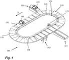
- FIG. 1 shows a weighing system 100 according to the invention.
- the weighing system 100 comprises a plurality of containers 110, the present example a tray 110, connected to a conveyor means 120.
- the conveyor means 120 comprises an array of concatenated conveyor bars 121 mutually hingedly connected to form an endless chain.
- the conveyor means also comprises an actuator 125 to drive the conveyor bars 120.
- Each conveyor bar 121 is connected to a tray 110, such that the tray 110 connected to it is conveyed in an horizontal position in a conveying direction defining an axis X, as shown by an arrow in Figure 1 .
- said trays 110 are also guided by a guide means 130 arranged in said weighing system 100.
- the tray 110 can be thus conveyed from a receiving section 101 to an outlet section 102 of the weighing system 100, and so does an item 195 being supported on top of the trays 110.
- the item 195 may be pushed by a pushing organ 198 arranged in the tray 110 at the outlet section 102 depending on its weight, as will be explained below.
- Figure 1 also shows that the weighing system 100 comprises a weighing device 160 arranged under the path of the trays 110, a location of which is suitable for collecting data relating to the weight of the item 195 being transported by one tray 110.
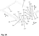
- Figure 2A shows a bottom view of a first embodiment of a tray 110 connected to the conveyor means 120 of the weighing system 100 depicted in figure 1 .
- the tray 110 is connected to the conveyor bar 121 via a primary connecting means 240, a secondary connecting means 250 and a further secondary connecting means 250'.
- the primary connecting means 240 comprises a primary first section 241 permanently connected to the tray 110, a primary second section 242 permanently connected to the conveyor bar 121, and a primary third section 243.
- the primary third section 243 comprises a primary first pin 246 arranged within a primary first opening of the primary first section 241. The cooperation of the primary first pin 246 and the primary first opening allows for hingedly connection of said primary third section 243 with the primary first section 241.
- said primary third section 243 is hingedly connected to the primary second section via a primary second pin 247 of said primary third section 243 and arranged within a primary second opening of said primary second section 242.
- the secondary connecting means 250 comprises a secondary first section 251, a secondary second section 252 and a secondary third section 253.
- the secondary third section 253 also comprises a secondary first pin 256 and a secondary second pin 257.
- the secondary third section 253 is hingedly connected to the secondary first section 251 via a secondary first opening arranged in said secondary first section 251 and to the secondary second section 252 via a secondary second opening arranged in said secondary second section 252.
- the further secondary connecting means 250' comprises a secondary first section 251', a secondary second section 252' and a secondary third section 253' hingedly connected to the secondary first section 251' by the cooperation of a secondary first pin 256' and secondary first opening and hingedly connected to the secondary second section 252' by the cooperation of a secondary second pin 257' and a secondary second opening.
- the primary connecting means 240 is arranged such that the longitudinal of both the primary first pin 246 and the primary second pin 247 are parallel with respect to an axis Y transverse to the axis X.
- the primary third section 243 is capable of rotating about an axis also transverse to said conveying axis X and parallel to the axis Y.
- secondary connecting means 250 and 250' are arranged such that the longitudinal of the secondary first pins 256 and 256' and the secondary second pins 257 and 257' are parallel with respect to the axis X.
- the secondary third sections 253 and 253' are capable of rotating about an axis substantially parallel to said axis X.
- the pushing organ 198 may move along the axis Y.
- FIG. 2B shows a lateral side view of a section of the guiding means 130 before and after the weighing device 160.
- the weighing device 160 forms a weighing area 261 supported by a frame 263.
- the weighing area 261 is arranged for weighing the items 195 supported on top of the trays 110.
- two photoelectric cells 264 and 264' may be arranged to cooperate with the weighing device 160, as will be explained below.
- the weighing device 160 is also in communication with a processing unit (not shown) connected to an actuator (not shown). The functions of them will be explained later.
- the tray 110 of the first embodiment comprises a first wheel 211', a second wheel 211" and a third wheel 211"' (see figure 2A ). These wheels are arranged are arranged in the tray 110 to cooperate with the guide means 130 of the weighing system 100.
- Figure 2C shows a top view of the section of the guide means 130 depicted in figure 2B and the wheels 211', 211" and 211'" of the tray 110 (the tray 110 itself is not depicted for the sake of clarity).
- the guide means 130 comprises a first rail 231' for receiving the first wheel 211', a second rail 231" that receives the second wheels 211" and a third rail 231"' that receives the third wheel 211"'.
- the cooperation allows for supporting the tray 110 in a stable arrangement while said tray 110 is being conveyed via the conveyor means 120. Further, the cooperation allows for supporting the tray 110 in a first vertical position with respect to the conveyor bar 121 when being conveyed towards the weighing device 160.
- the weighing area 261 comprises a first rail 261' a second rail 261" and a third rail 261"'.
- the rail 261' prolongs from the first rail 231' in the conveying direction and, therefore, receives the wheel 211'.
- the rail 261"and the rail 261"' receive the second wheel 211" and third wheel 211"' respectively. In this way, when said wheels 211', 211" and 211"' are supported on these rails 261', 261" and 261'" the weight of the tray 110 may be determined by the weighing device 160.
- the controller of the weighing device 160 may determine the moment at which the weight is measured using data from the photoelectric cells 264 and 264' about the presence of the tray 110 and the item 195 to be weighed in the rails 261', 261" and 261"'. It is important to note that other means may be used for the detection of the tray, for example by use in combination of an encoder and a proximity switch.
- the tray 110 may move in a vertical direction along an axis Z transverse to the conveying direction independently with respect to the conveyor bar 121 by the rotation of the primary third section 243, the secondary third section 253 and the further secondary third section 253' when being conveyed (see figure 2A ).
- the weighing device may determine the weight. Further, an effect that the conveyor bar 121 may cause on the load is negligible.
- the movement that the tray 110 may suffer along the axis X as said tray 110 is being conveyed in the conveying direction is reduced by the primary first and second pins 246 and 247. Also, the movement of the tray 110 along the axis Y is reduced by the secondary first and second pins 256 and 257 and the further secondary first and second pins 256' and 257'. In this way, the rotation in the plane defined by weighing area 261 is reduced, and the weight obtained by the weighing device 160 is more accurate.
- the tray 110 reaches the guide means 130 again to reach the first vertical position. Then it is conveyed to the outlet section 102 of the weighing system 100. There, depending on the weight of the item 195 determined by the controller, the pushing organ 198 is actuated to deliver the item 195 out of said tray 110.
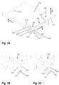
- Figure 3A shows the tray 110 connected to the conveyor bar 121 via a primary connection means 240 as explained above and a second example of a secondary connecting means 350 and a further secondary connecting means 350'. Since both the secondary connecting means 350 and the further secondary connecting means 350' are identical, only the latter will be explained in detail.
- the further secondary connecting means 350' is a secondary connecting means 250 as depicted in figure 2A although further comprising a secondary fourth section 354' and a secondary fifth section 355'.
- the secondary fourth section 354' extends from the secondary first section 251' and comprises a further pin 357'.
- the secondary fifth section 355' extends from the secondary second section 252' and comprises a further opening 358' oversized with respect to the size of the further pin 357'.
- the secondary fourth section 354' and the fifth section 355' cooperate together via the further pin 357' and the further opening 358'.
- Figure 3B depicts the secondary fourth section 354' being supported by the secondary fifth section 355' when the further pin 357' is fixed within a recess 359' arranged in said further opening 358'. In this way, the rotation of the secondary third section 253' is prevented and the tray 110 may be supported in a fixed position ( figure 3B ).
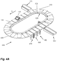
- the tray 110 comprising such a secondary connecting means 350 and 350' may be used in a weighing system 400 (see figure 4A ). Said tray 110 may be thus conveyed in the first vertical position while being supported by a guide means 430.
- the guide means 430 comprises only one rail 431 for supporting the first wheel 211' of the tray 110. This means that the wheels 211" and 211'" need not to be supported because the system 430 is arranged such that the rail 431 support the tray 110 in the fixed position (see figure 4C ).
- the lifting device 470 is arranged upstream the weighing device 160 in the conveying direction (see figure 4A ). It comprises a receiving area 471 supported by a frame 473 (see figure 4B ). In the conveying direction, the receiving area 471 defines a positive slope towards the weighing area 261, said receiving area 471 being thus adjacent to the weighing area 261.
- the receiving area 471 comprises rails 471', 471" and 471'" arranged for receiving the wheels 211, 211" and 211"' of the tray 110 and for moving them upwardly such that said tray 110 is moved also upwardly with respect to the conveyor bar 121 to reach the unfixed position when being supported by the weighing area 261.
- the weight of the tray 110 supporting the item 195 is weighed by the weighing device 160 in the unfixed position, and the effect of the conveyor bar 121 on the load generated by the weight if said tray 110 and the item 195 on the weighing area 261 is negligible.
- the weighing system 400 also comprises a setting-down device 480 arranged downstream the weighing device 160 in the conveying direction.
- the setting-down device 480 comprises a frame 483 for supporting a setting-down area 481 arranged such that in the conveying direction X said setting-down area 481 defines a negative slope starting beside the weighing area 261.
- rails 481', 481" and 481"' defining said setting-down area 481 guide the wheels 211', 211" and 211"' downwardly from the when said tray is being conveyed.
- a downward movement of the tray 110 with respect to the conveyor bar 121 is allowed due to gravity, said tray 110 reaching again the fixed position.
- the secondary connecting means 350 and 350" may support the tray 110 without need of using a guide means 130 or 430 since the tray 110 is supported in the fixed position.
- a weighing system with no guide means may be used, said weighing system comprising at least a lifting device and, advantageously, a setting-down device.
- Figure 5 shows a different example of a tray 110 connected to a conveyor bar 121 via a secondary connecting means 550 and a further secondary connecting means 550'. Since both of them are identical, only the secondary connecting means 550 will be explained in detail.
- a second opening 558 of the secondary connection means 550 is designed elongated in the axis Z such that said second opening allows the second pin 557 moving within said second opening. In this way the tray 110 may move in the vertical direction with respect to the conveyor bar 121.
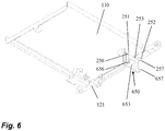
- Figure 6 shows another example of a container comprising a secondary connecting means 650.
- Said secondary connecting means also connects the tray 110 to the conveyor bar 121.
- the secondary connecting means 650 is a secondary connecting means 250 further comprising a further secondary third section 653 arranged in a parallelepiped arrangement with respect to the third section 253 via a further secondary first pin 656 and a further secondary second pin 657of said secondary connecting means.
- the parallelepiped arrangement constrain rotation of the tray 110 about the axis X caused by the load provided by the item 195 when being conveyed, for example when used in the weighing system 400.
Landscapes
- Physics & Mathematics (AREA)
- General Physics & Mathematics (AREA)
- Engineering & Computer Science (AREA)
- Mechanical Engineering (AREA)
- Weight Measurement For Supplying Or Discharging Of Specified Amounts Of Material (AREA)
Claims (12)
- Wiegesystem (100, 400) zum Wiegen eines Gegenstands (195), wenn von einer Empfangssektion (101) zu einer Auslasssektion (102) gefördert, wobei das Wiegesystem (100, 400) umfasst:- mindestens ein Behältnis (110) zum Transportieren des Gegenstands (195);- ein Fördermittel (120), verbunden mit dem Behältnis (110) zum Fördern in einer Förderrichtung des Behältnisses (110) zu einer ersten vertikalen Position relativ zu den Fördermitteln (120); und- eine Wiegevorrichtung (160) zum Wiegen des Behältnisses (110), wenn das Behältnis (110) gefördert wird, gestützt auf der Wiegevorrichtung (160);
wobei das Behältnis (110) mit den Fördermitteln (120) verbunden ist über ein primäres Verbindungsmittel (240) und ein sekundäres Verbindungsmittel (250), wobei jedes der zwei Verbindungsmittel eine erste Sektion (241, 251) umfasst, permanent verbunden mit dem Behältnis (110), eine zweite Sektion (242, 252), permanent verbunden mit den Fördermitteln, und eine dritte Sektion (243, 253), klappbar verbunden mit sowohl der ersten Sektion (241, 251) als auch der zweiten Sektion (242, 252);
und wobei beide Verbindungsmittel so angeordnet sind, dass die dritte Sektion (243) der primären Verbindungsmittel (240) rotierbar ist um eine erste Achse, transversal zu der Förderrichtung, und die dritte Sektion (253) der sekundären Verbindungsmittel (250) rotierbar ist um eine zweite Achse, im Wesentlichen parallel zu der Förderrichtung, sodass die Rotation der dritten Sektionen (243, 253) um die erste Ache und die zweite Achse entsprechend Bewegung des Behältnisses (110) in Bezug auf die Fördermittel (120) in einer vertikalen Richtung von der ersten vertikalen Position in eine zweite vertikale Position erlauben. - Wiegesystem (100, 400) nach Anspruch 1, wobei für die primären Verbindungsmittel (240) und die sekundären Verbindungsmittel (250), die dritte Sektion (243, 253) klappbar verbunden ist mit der ersten Sektion (241, 251) über einen ersten Stift (246, 256), angeordnet innerhalb einer ersten Öffnung und die zweite Sektion (242, 252) über einen zweiten Stift (247, 257), angeordnet innerhalb einer zweiten Öffnung; wobei für die primären Verbindungsmittel (240) der erste Stift (246) und der zweite Stift (247) transversal zu der Förderrichtung angeordnet sind, und wobei für die sekundären Verbindungsmittel (250) der erste Stift (256) und der zweite Stift (257) im Wesentlichen parallel zu der Förderrichtung sind.
- Wiegesystem (100, 400) nach Anspruch 2, wobei die zweite Öffnung (358) der sekundären Verbindungsmittel (550) designt ist, sodass die zweite Öffnung (358) sich in einer dritten Achse erstreckt, transversal sowohl zu der ersten Achse als auch der zweiten Achse, sodass der zweite Stift (557) des zweiten Verbindungsmittels (550) in der Lage ist, sich innerhalb der zweiten Öffnung zu bewegen, wenn das Behältnis (110) sich zwischen der ersten vertikalen Position und der zweiten vertikalen Position bewegt.
- Wiegesystem (100, 400) nach einem der vorstehenden Ansprüche, wobei die sekundären Verbindungsmittel (650) eine weitere dritte Sektion (653) umfassen, ebenso klappbar verbunden mit sowohl der ersten Sektion (251) als auch der zweiten Sektion (252) der sekundären Verbindungsmittel (250) und wobei die weitere dritte Sektion in einer parallelepipedischen Anordnung in Bezug auf die dritte Sektion (253) der sekundären Verbindungsmittel (250) ist.
- Wiegesystem (400) nach einem der vorstehenden Ansprüche, wobei mindestens eines der primären Verbindungsmittel oder der sekundären Verbindungsmittel (350) eine vierte Sektion (354) umfasst, die sich von der ersten Sektion erstreckt, und eine fünfte Sektion (355), die sich von der zweiten Sektion erstreckt, wobei die vierte Sektion (354) und die fünfte Sektion (355) designt sind zum miteinander Kooperieren über einen weiteren Stift (357) und eine weitere Öffnung (358), überdimensioniert in Bezug auf den weiteren Stift (357), wobei die weitere Öffnung (358) ebenso eine Aussparung (359) umfasst, sodass, wenn das Behältnis (110) in der ersten vertikalen Position ist, die vierte Sektion (354) gestützt wird mittels der fünften Sektion (355) über den Stift, fixiert innerhalb der Aussparung (359), und sodass, wenn das Behältnis (110) sich in Richtung der zweiten vertikalen Position bewegt, die vierte Sektion (354) gelöst wird von der fünften Sektion (355) während der Stift innerhalb der weiteren Öffnung (358) angeordnet ist, wobei die zweite vertikale Position höher ist als die erste vertikale Position; und wobei das Wiegesystem (400) stromaufwärts relativ zu der Wiegevorrichtung (160) eine Hebevorrichtung (470) zum Bewegen des Behältnisses (110) relativ zu den Fördermitteln (120) von der ersten vertikalen Position in Richtung auf die zweite vertikale Position umfasst, sodass das Behältnis (110) gefördert wird, gestützt auf der Wiegevorrichtung (160) in der zweiten vertikalen Position.
- Wiegesystem (400) nach Anspruch 5, wobei die Hebevorrichtung (470) einen Rahmen (473) umfasst, wobei der Rahmen (473) einen Empfangsbereich (471) umfasst, benachbart zu der Wiegevorrichtung (160), wobei der Empfangsbereich (471) konfiguriert ist, wenn das Behältnis (110) gefördert wird, umi) das Behältnis (110) in der ersten vertikalen Position zu empfangen und;ii) das Behältnis (110) aufwärts in Richtung der zweiten vertikalen Position zu führen, sodass der weitere Stift (357) aus der Aussparung (359) in Richtung auf die überdimensionierte weitere Öffnung (358) bewegt wird.
- Wiegesystem (400) nach Anspruch 5 oder 6, wobei das Wiegesystem (400) weiter eine Absetzvorrichtung (480) umfasst, angeordnet benachbart zu der Wiegevorrichtung (160), wobei die Absetzvorrichtung (480) einen Rahmen (483) umfasst, wobei der Rahmen (483) einen Absetzbereich (481) umfasst, konfiguriert, wenn das Behältnis (110) mittels der Fördermittel (120) gefördert wird, umi) das Behältnis (110) in der zweiten vertikalen Position von der Wiegevorrichtung (160) zu empfangen und;ii) das Behältnis (110) von der zweiten vertikalen Position in Richtung auf die erste vertikale Position zu führen, sodass der weitere Stift (357) in der Aussparung (359) fixiert ist.
- Wiegesystem (100, 400) nach einem der vorstehenden Ansprüche, wobei die primären Verbindungsmittel (240) und die sekundären Verbindungsmittel (250) angeordnet sind, sodass die zweite Sektion (242) der primären Verbindungsmittel (240) gegenüberliegend den sekundären Verbindungsmitteln (250) ist und wobei das Behältnis (110) ein weiteres sekundäres Verbindungsmittel (250') umfasst, angeordnet gegenüberliegend der ersten Sektion (241) des primären Verbindungsmittels (240).
- Wiegesystem (100, 400) nach einem der vorstehenden Ansprüche, wobei das Behältnis (110) weiter Rollmittel zum Stützen des Behältnisses auf der Wiegevorrichtung umfasst und zum Kooperieren mit den Fördermitteln (120) zum Fördern des Behältnisses, während es auf der Wiegevorrichtung gestützt ist.
- Wiegesystem (100, 400) nach Anspruch 9, wobei das Wiegesystem (100, 400) weiter Führungsmittel (130) umfasst, angeordnet in Kooperation mit den Rollmitteln (111) zum Stützen des Behältnisses (110) in der ersten vertikalen Position, wenn es gefördert wird.
- Wiegesystem (400) nach Anspruch 10, wenn in Kombination mit Anspruch 6, wobei die Führungsmittel (130) angeordnet sind in Kooperation mit der Hebevorrichtung (470), sodass der Empfangsbereich (471) das Behältnis (110) empfängt über die Rollmittel (211).
- Wiegesystem (400) nach Anspruch 10, wenn in Kombination mit Anspruch 7, wobei die Führungsmittel (130) angeordnet sind in Kooperation mit der Absetzvorrichtung (480), sodass die Führungsmittel (130) aus dem Absetzbereich (481) das Behältnis (110) über die Rollmittel (111) empfangen.
Applications Claiming Priority (2)
| Application Number | Priority Date | Filing Date | Title |
|---|---|---|---|
| NL2017181A NL2017181B1 (en) | 2016-07-18 | 2016-07-18 | A weighing system |
| PCT/NL2017/050479 WO2018016946A1 (en) | 2016-07-18 | 2017-07-17 | A weighing system |
Publications (2)
| Publication Number | Publication Date |
|---|---|
| EP3485241A1 EP3485241A1 (de) | 2019-05-22 |
| EP3485241B1 true EP3485241B1 (de) | 2020-07-22 |
Family
ID=59702785
Family Applications (1)
| Application Number | Title | Priority Date | Filing Date |
|---|---|---|---|
| EP17757907.5A Active EP3485241B1 (de) | 2016-07-18 | 2017-07-17 | Wägesystem |
Country Status (5)
| Country | Link |
|---|---|
| US (1) | US11280662B2 (de) |
| EP (1) | EP3485241B1 (de) |
| ES (1) | ES2826855T3 (de) |
| NL (1) | NL2017181B1 (de) |
| WO (1) | WO2018016946A1 (de) |
Families Citing this family (3)
| Publication number | Priority date | Publication date | Assignee | Title |
|---|---|---|---|---|
| NL2020297B1 (en) | 2018-01-18 | 2019-07-29 | Optimus Sorter Holding B V | A weighing system |
| CN116689318A (zh) * | 2023-06-12 | 2023-09-05 | 维达纸业(中国)有限公司 | 一种抹巾生产装置 |
| CN119976230A (zh) * | 2025-03-26 | 2025-05-13 | 香港科技大学(广州) | 一种自动称重配料运输传动装置 |
Family Cites Families (16)
| Publication number | Priority date | Publication date | Assignee | Title |
|---|---|---|---|---|
| US1404591A (en) | 1920-03-13 | 1922-01-24 | Fredrickson Christian | Conveying apparatus |
| US3454614A (en) | 1965-03-29 | 1969-07-08 | Chiyoda Chem Eng Construct Co | Methods of manufacturing alkali dialkylaluminates |
| US3918587A (en) | 1973-11-16 | 1975-11-11 | Gainesville Machine Company In | Apparatus for detecting and dispensing articles of preselected weights suspended from shackles |
| US4187945A (en) | 1978-06-29 | 1980-02-12 | W. F. Altenpohl, Inc. | Plural path weight sorting system |
| US4957619A (en) * | 1988-09-23 | 1990-09-18 | Powell Machinery, Inc. | Self-singulating weight sizer |
| NL9101821A (nl) * | 1991-10-30 | 1993-05-17 | Tas Adrianus Wilhelmus | Werkwijze en inrichting voor het op gewicht sorteren van in hoofdzaak ronde produkten. |
| IT1257787B (it) | 1992-05-07 | 1996-02-13 | Sammo Srl | Apparecchiatura automatica per singolarizzare e calibrare in peso prodotti ortofrutticoli tondeggianti di varie forma e dimensioni |
| IT1294114B1 (it) | 1997-01-23 | 1999-03-22 | Unitec Srl | Impianto perfezionato di trasporto e di pesatura automatica di prodotti singoli, in particolare vegetali |
| ITMO20050154A1 (it) | 2005-06-17 | 2006-12-18 | Bastoni Danilo | Dispositivo modulare per il supporto di prodotti agricoli su macchine calibratrici o simil. |
| NL1033567C2 (nl) | 2007-03-20 | 2008-09-23 | Lwf Holding B V | Transportsysteem. |
| NL2012822B1 (nl) | 2014-05-15 | 2016-03-02 | Optimus Sorter Holding B V | Sorteerinrichting. |
| NL2013604B1 (nl) | 2014-10-09 | 2016-10-04 | Optimus Sorter Holding B V | Inrichting voor het laden, transporteren en lossen van voorwerpen. |
| NL2014325B1 (en) * | 2015-02-20 | 2016-10-13 | Optimus Sorter Holding B V | A conveyor system comprising a plurality of support members and a method thereof. |
| NL2020297B1 (en) * | 2018-01-18 | 2019-07-29 | Optimus Sorter Holding B V | A weighing system |
| NL2020334B1 (en) * | 2018-01-26 | 2019-07-31 | Optimus Sorter Holding B V | Sorting device with improved capacity |
| NL2022537B1 (en) * | 2019-02-08 | 2020-08-19 | Optimus Sorter Holding B V | A device comprising a conveyor |
-
2016
- 2016-07-18 NL NL2017181A patent/NL2017181B1/en not_active IP Right Cessation
-
2017
- 2017-07-17 ES ES17757907T patent/ES2826855T3/es active Active
- 2017-07-17 EP EP17757907.5A patent/EP3485241B1/de active Active
- 2017-07-17 WO PCT/NL2017/050479 patent/WO2018016946A1/en not_active Ceased
- 2017-07-17 US US16/319,154 patent/US11280662B2/en active Active
Non-Patent Citations (1)
| Title |
|---|
| None * |
Also Published As
| Publication number | Publication date |
|---|---|
| ES2826855T3 (es) | 2021-05-19 |
| US11280662B2 (en) | 2022-03-22 |
| NL2017181B1 (en) | 2018-01-24 |
| US20210333143A1 (en) | 2021-10-28 |
| WO2018016946A1 (en) | 2018-01-25 |
| EP3485241A1 (de) | 2019-05-22 |
Similar Documents
| Publication | Publication Date | Title |
|---|---|---|
| EP3059561B1 (de) | Fördersystem mit einer vielzahl an stützelementen und verfahren dafür | |
| US10683167B2 (en) | Automated warehouse and suspension-type stacker crane | |
| US10633195B2 (en) | Device for loading and unloading rail-guided suspended conveyor systems | |
| JP7408891B2 (ja) | 物品移載装置及び物品移載システム | |
| CN102015493B (zh) | 用于产品输送的装置 | |
| EP2960184A1 (de) | Automatischer laden, insbesondere geeignet für automatische apotheken | |
| US11280662B2 (en) | Weighing system for item in container on conveyor | |
| US8237067B2 (en) | Checkweigher with independent scales | |
| EP3274105A1 (de) | Gestapelte geneigte ablage und kreuzband-sortiersystem | |
| EP4245693B1 (de) | Lagereinrichtung für artikel | |
| KR102681532B1 (ko) | 반송 분류 장치 | |
| JP2018076176A (ja) | 物品取出装置及び物品搬送システム | |
| US20180111754A1 (en) | Suspension-type stacker crane | |
| US11708219B1 (en) | Mobile, rotatable, transport mechanism with multiple conveyor sections | |
| AU2016354925A1 (en) | Conveying system | |
| EP3514510B1 (de) | Wägesystem | |
| US10494189B2 (en) | Apparatus for multi-axial transfer of objects in assembly lines | |
| JP6427361B2 (ja) | 搬送物収納設備 | |
| JP2018145001A (ja) | コンベヤシステム | |
| KR101674662B1 (ko) | 트레이 대기 및 반출 장치 | |
| JP5614161B2 (ja) | 位置決め装置 | |
| JP6507728B2 (ja) | 昇降搬送装置 | |
| JP6176167B2 (ja) | 物品搬送設備 | |
| JP6705350B2 (ja) | 荷積込装置 | |
| JP2015174007A (ja) | 紙葉類移載機構 |
Legal Events
| Date | Code | Title | Description |
|---|---|---|---|
| STAA | Information on the status of an ep patent application or granted ep patent |
Free format text: STATUS: UNKNOWN |
|
| STAA | Information on the status of an ep patent application or granted ep patent |
Free format text: STATUS: THE INTERNATIONAL PUBLICATION HAS BEEN MADE |
|
| PUAI | Public reference made under article 153(3) epc to a published international application that has entered the european phase |
Free format text: ORIGINAL CODE: 0009012 |
|
| STAA | Information on the status of an ep patent application or granted ep patent |
Free format text: STATUS: REQUEST FOR EXAMINATION WAS MADE |
|
| 17P | Request for examination filed |
Effective date: 20190129 |
|
| AK | Designated contracting states |
Kind code of ref document: A1 Designated state(s): AL AT BE BG CH CY CZ DE DK EE ES FI FR GB GR HR HU IE IS IT LI LT LU LV MC MK MT NL NO PL PT RO RS SE SI SK SM TR |
|
| AX | Request for extension of the european patent |
Extension state: BA ME |
|
| DAV | Request for validation of the european patent (deleted) | ||
| DAX | Request for extension of the european patent (deleted) | ||
| GRAP | Despatch of communication of intention to grant a patent |
Free format text: ORIGINAL CODE: EPIDOSNIGR1 |
|
| STAA | Information on the status of an ep patent application or granted ep patent |
Free format text: STATUS: GRANT OF PATENT IS INTENDED |
|
| INTG | Intention to grant announced |
Effective date: 20200220 |
|
| GRAS | Grant fee paid |
Free format text: ORIGINAL CODE: EPIDOSNIGR3 |
|
| GRAA | (expected) grant |
Free format text: ORIGINAL CODE: 0009210 |
|
| STAA | Information on the status of an ep patent application or granted ep patent |
Free format text: STATUS: THE PATENT HAS BEEN GRANTED |
|
| AK | Designated contracting states |
Kind code of ref document: B1 Designated state(s): AL AT BE BG CH CY CZ DE DK EE ES FI FR GB GR HR HU IE IS IT LI LT LU LV MC MK MT NL NO PL PT RO RS SE SI SK SM TR |
|
| REG | Reference to a national code |
Ref country code: GB Ref legal event code: FG4D |
|
| REG | Reference to a national code |
Ref country code: CH Ref legal event code: EP |
|
| REG | Reference to a national code |
Ref country code: DE Ref legal event code: R096 Ref document number: 602017020243 Country of ref document: DE |
|
| REG | Reference to a national code |
Ref country code: AT Ref legal event code: REF Ref document number: 1293838 Country of ref document: AT Kind code of ref document: T Effective date: 20200815 |
|
| REG | Reference to a national code |
Ref country code: IE Ref legal event code: FG4D |
|
| REG | Reference to a national code |
Ref country code: NL Ref legal event code: FP |
|
| REG | Reference to a national code |
Ref country code: LT Ref legal event code: MG4D |
|
| REG | Reference to a national code |
Ref country code: AT Ref legal event code: MK05 Ref document number: 1293838 Country of ref document: AT Kind code of ref document: T Effective date: 20200722 |
|
| PG25 | Lapsed in a contracting state [announced via postgrant information from national office to epo] |
Ref country code: LT Free format text: LAPSE BECAUSE OF FAILURE TO SUBMIT A TRANSLATION OF THE DESCRIPTION OR TO PAY THE FEE WITHIN THE PRESCRIBED TIME-LIMIT Effective date: 20200722 Ref country code: PT Free format text: LAPSE BECAUSE OF FAILURE TO SUBMIT A TRANSLATION OF THE DESCRIPTION OR TO PAY THE FEE WITHIN THE PRESCRIBED TIME-LIMIT Effective date: 20201123 Ref country code: HR Free format text: LAPSE BECAUSE OF FAILURE TO SUBMIT A TRANSLATION OF THE DESCRIPTION OR TO PAY THE FEE WITHIN THE PRESCRIBED TIME-LIMIT Effective date: 20200722 Ref country code: BG Free format text: LAPSE BECAUSE OF FAILURE TO SUBMIT A TRANSLATION OF THE DESCRIPTION OR TO PAY THE FEE WITHIN THE PRESCRIBED TIME-LIMIT Effective date: 20201022 Ref country code: SE Free format text: LAPSE BECAUSE OF FAILURE TO SUBMIT A TRANSLATION OF THE DESCRIPTION OR TO PAY THE FEE WITHIN THE PRESCRIBED TIME-LIMIT Effective date: 20200722 Ref country code: GR Free format text: LAPSE BECAUSE OF FAILURE TO SUBMIT A TRANSLATION OF THE DESCRIPTION OR TO PAY THE FEE WITHIN THE PRESCRIBED TIME-LIMIT Effective date: 20201023 Ref country code: NO Free format text: LAPSE BECAUSE OF FAILURE TO SUBMIT A TRANSLATION OF THE DESCRIPTION OR TO PAY THE FEE WITHIN THE PRESCRIBED TIME-LIMIT Effective date: 20201022 Ref country code: FI Free format text: LAPSE BECAUSE OF FAILURE TO SUBMIT A TRANSLATION OF THE DESCRIPTION OR TO PAY THE FEE WITHIN THE PRESCRIBED TIME-LIMIT Effective date: 20200722 Ref country code: AT Free format text: LAPSE BECAUSE OF FAILURE TO SUBMIT A TRANSLATION OF THE DESCRIPTION OR TO PAY THE FEE WITHIN THE PRESCRIBED TIME-LIMIT Effective date: 20200722 |
|
| PG25 | Lapsed in a contracting state [announced via postgrant information from national office to epo] |
Ref country code: RS Free format text: LAPSE BECAUSE OF FAILURE TO SUBMIT A TRANSLATION OF THE DESCRIPTION OR TO PAY THE FEE WITHIN THE PRESCRIBED TIME-LIMIT Effective date: 20200722 Ref country code: LV Free format text: LAPSE BECAUSE OF FAILURE TO SUBMIT A TRANSLATION OF THE DESCRIPTION OR TO PAY THE FEE WITHIN THE PRESCRIBED TIME-LIMIT Effective date: 20200722 Ref country code: PL Free format text: LAPSE BECAUSE OF FAILURE TO SUBMIT A TRANSLATION OF THE DESCRIPTION OR TO PAY THE FEE WITHIN THE PRESCRIBED TIME-LIMIT Effective date: 20200722 Ref country code: IS Free format text: LAPSE BECAUSE OF FAILURE TO SUBMIT A TRANSLATION OF THE DESCRIPTION OR TO PAY THE FEE WITHIN THE PRESCRIBED TIME-LIMIT Effective date: 20201122 |
|
| REG | Reference to a national code |
Ref country code: DE Ref legal event code: R097 Ref document number: 602017020243 Country of ref document: DE |
|
| PG25 | Lapsed in a contracting state [announced via postgrant information from national office to epo] |
Ref country code: CZ Free format text: LAPSE BECAUSE OF FAILURE TO SUBMIT A TRANSLATION OF THE DESCRIPTION OR TO PAY THE FEE WITHIN THE PRESCRIBED TIME-LIMIT Effective date: 20200722 Ref country code: DK Free format text: LAPSE BECAUSE OF FAILURE TO SUBMIT A TRANSLATION OF THE DESCRIPTION OR TO PAY THE FEE WITHIN THE PRESCRIBED TIME-LIMIT Effective date: 20200722 Ref country code: RO Free format text: LAPSE BECAUSE OF FAILURE TO SUBMIT A TRANSLATION OF THE DESCRIPTION OR TO PAY THE FEE WITHIN THE PRESCRIBED TIME-LIMIT Effective date: 20200722 Ref country code: IT Free format text: LAPSE BECAUSE OF FAILURE TO SUBMIT A TRANSLATION OF THE DESCRIPTION OR TO PAY THE FEE WITHIN THE PRESCRIBED TIME-LIMIT Effective date: 20200722 Ref country code: EE Free format text: LAPSE BECAUSE OF FAILURE TO SUBMIT A TRANSLATION OF THE DESCRIPTION OR TO PAY THE FEE WITHIN THE PRESCRIBED TIME-LIMIT Effective date: 20200722 Ref country code: SM Free format text: LAPSE BECAUSE OF FAILURE TO SUBMIT A TRANSLATION OF THE DESCRIPTION OR TO PAY THE FEE WITHIN THE PRESCRIBED TIME-LIMIT Effective date: 20200722 |
|
| REG | Reference to a national code |
Ref country code: ES Ref legal event code: FG2A Ref document number: 2826855 Country of ref document: ES Kind code of ref document: T3 Effective date: 20210519 |
|
| PLBE | No opposition filed within time limit |
Free format text: ORIGINAL CODE: 0009261 |
|
| STAA | Information on the status of an ep patent application or granted ep patent |
Free format text: STATUS: NO OPPOSITION FILED WITHIN TIME LIMIT |
|
| PG25 | Lapsed in a contracting state [announced via postgrant information from national office to epo] |
Ref country code: AL Free format text: LAPSE BECAUSE OF FAILURE TO SUBMIT A TRANSLATION OF THE DESCRIPTION OR TO PAY THE FEE WITHIN THE PRESCRIBED TIME-LIMIT Effective date: 20200722 |
|
| 26N | No opposition filed |
Effective date: 20210423 |
|
| PG25 | Lapsed in a contracting state [announced via postgrant information from national office to epo] |
Ref country code: SK Free format text: LAPSE BECAUSE OF FAILURE TO SUBMIT A TRANSLATION OF THE DESCRIPTION OR TO PAY THE FEE WITHIN THE PRESCRIBED TIME-LIMIT Effective date: 20200722 |
|
| PG25 | Lapsed in a contracting state [announced via postgrant information from national office to epo] |
Ref country code: SI Free format text: LAPSE BECAUSE OF FAILURE TO SUBMIT A TRANSLATION OF THE DESCRIPTION OR TO PAY THE FEE WITHIN THE PRESCRIBED TIME-LIMIT Effective date: 20200722 |
|
| REG | Reference to a national code |
Ref country code: CH Ref legal event code: PL |
|
| PG25 | Lapsed in a contracting state [announced via postgrant information from national office to epo] |
Ref country code: MC Free format text: LAPSE BECAUSE OF FAILURE TO SUBMIT A TRANSLATION OF THE DESCRIPTION OR TO PAY THE FEE WITHIN THE PRESCRIBED TIME-LIMIT Effective date: 20200722 |
|
| PG25 | Lapsed in a contracting state [announced via postgrant information from national office to epo] |
Ref country code: LI Free format text: LAPSE BECAUSE OF NON-PAYMENT OF DUE FEES Effective date: 20210731 Ref country code: CH Free format text: LAPSE BECAUSE OF NON-PAYMENT OF DUE FEES Effective date: 20210731 |
|
| PG25 | Lapsed in a contracting state [announced via postgrant information from national office to epo] |
Ref country code: LU Free format text: LAPSE BECAUSE OF NON-PAYMENT OF DUE FEES Effective date: 20210717 |
|
| REG | Reference to a national code |
Ref country code: DE Ref legal event code: R081 Ref document number: 602017020243 Country of ref document: DE Owner name: BOEWE SYSTEC GMBH, DE Free format text: FORMER OWNER: OPTIMUS SORTER HOLDING B.V., BEUNINGEN, NL |
|
| REG | Reference to a national code |
Ref country code: ES Ref legal event code: PC2A Owner name: BOEWE SYSTEC GMBH Effective date: 20220712 |
|
| REG | Reference to a national code |
Ref country code: NL Ref legal event code: PD Owner name: BOEWE SYSTEC GMBH; DE Free format text: DETAILS ASSIGNMENT: CHANGE OF OWNER(S), ASSIGNMENT; FORMER OWNER NAME: OPTIMUS SORTER HOLDING B.V. Effective date: 20220708 |
|
| REG | Reference to a national code |
Ref country code: GB Ref legal event code: 732E Free format text: REGISTERED BETWEEN 20220630 AND 20220706 |
|
| PG25 | Lapsed in a contracting state [announced via postgrant information from national office to epo] |
Ref country code: IE Free format text: LAPSE BECAUSE OF NON-PAYMENT OF DUE FEES Effective date: 20210717 |
|
| REG | Reference to a national code |
Ref country code: BE Ref legal event code: PD Owner name: BOEWE SYSTEC GMBH; DE Free format text: DETAILS ASSIGNMENT: CHANGE OF OWNER(S), ASSIGNMENT; FORMER OWNER NAME: OPTIMUS SORTER HOLDING B.V. Effective date: 20220623 |
|
| P01 | Opt-out of the competence of the unified patent court (upc) registered |
Effective date: 20230308 |
|
| PG25 | Lapsed in a contracting state [announced via postgrant information from national office to epo] |
Ref country code: CY Free format text: LAPSE BECAUSE OF FAILURE TO SUBMIT A TRANSLATION OF THE DESCRIPTION OR TO PAY THE FEE WITHIN THE PRESCRIBED TIME-LIMIT Effective date: 20200722 |
|
| PG25 | Lapsed in a contracting state [announced via postgrant information from national office to epo] |
Ref country code: HU Free format text: LAPSE BECAUSE OF FAILURE TO SUBMIT A TRANSLATION OF THE DESCRIPTION OR TO PAY THE FEE WITHIN THE PRESCRIBED TIME-LIMIT; INVALID AB INITIO Effective date: 20170717 |
|
| PG25 | Lapsed in a contracting state [announced via postgrant information from national office to epo] |
Ref country code: MK Free format text: LAPSE BECAUSE OF FAILURE TO SUBMIT A TRANSLATION OF THE DESCRIPTION OR TO PAY THE FEE WITHIN THE PRESCRIBED TIME-LIMIT Effective date: 20200722 |
|
| PG25 | Lapsed in a contracting state [announced via postgrant information from national office to epo] |
Ref country code: TR Free format text: LAPSE BECAUSE OF FAILURE TO SUBMIT A TRANSLATION OF THE DESCRIPTION OR TO PAY THE FEE WITHIN THE PRESCRIBED TIME-LIMIT Effective date: 20200722 |
|
| PG25 | Lapsed in a contracting state [announced via postgrant information from national office to epo] |
Ref country code: MT Free format text: LAPSE BECAUSE OF FAILURE TO SUBMIT A TRANSLATION OF THE DESCRIPTION OR TO PAY THE FEE WITHIN THE PRESCRIBED TIME-LIMIT Effective date: 20200722 |
|
| PGFP | Annual fee paid to national office [announced via postgrant information from national office to epo] |
Ref country code: NL Payment date: 20250721 Year of fee payment: 9 |
|
| PGFP | Annual fee paid to national office [announced via postgrant information from national office to epo] |
Ref country code: ES Payment date: 20250826 Year of fee payment: 9 |
|
| PGFP | Annual fee paid to national office [announced via postgrant information from national office to epo] |
Ref country code: DE Payment date: 20250722 Year of fee payment: 9 |
|
| PGFP | Annual fee paid to national office [announced via postgrant information from national office to epo] |
Ref country code: GB Payment date: 20250722 Year of fee payment: 9 Ref country code: BE Payment date: 20250721 Year of fee payment: 9 |
|
| PGFP | Annual fee paid to national office [announced via postgrant information from national office to epo] |
Ref country code: FR Payment date: 20250725 Year of fee payment: 9 |