EP3514061A1 - Landung von unbemannten luftfahrzeugen auf transportfahrzeugen zum transport - Google Patents
Landung von unbemannten luftfahrzeugen auf transportfahrzeugen zum transport Download PDFInfo
- Publication number
- EP3514061A1 EP3514061A1 EP19154613.4A EP19154613A EP3514061A1 EP 3514061 A1 EP3514061 A1 EP 3514061A1 EP 19154613 A EP19154613 A EP 19154613A EP 3514061 A1 EP3514061 A1 EP 3514061A1
- Authority
- EP
- European Patent Office
- Prior art keywords
- uav
- transportation vehicle
- transportation
- vehicles
- destination
- Prior art date
- Legal status (The legal status is an assumption and is not a legal conclusion. Google has not performed a legal analysis and makes no representation as to the accuracy of the status listed.)
- Granted
Links
- 238000000034 method Methods 0.000 claims abstract description 90
- 238000012384 transportation and delivery Methods 0.000 claims abstract description 47
- 230000015654 memory Effects 0.000 claims description 30
- 238000005007 materials handling Methods 0.000 claims description 28
- 238000011156 evaluation Methods 0.000 claims description 6
- 238000007726 management method Methods 0.000 description 36
- 238000010586 diagram Methods 0.000 description 30
- 230000008569 process Effects 0.000 description 29
- 230000007246 mechanism Effects 0.000 description 22
- 238000004891 communication Methods 0.000 description 21
- 238000003860 storage Methods 0.000 description 17
- 239000003795 chemical substances by application Substances 0.000 description 9
- 230000005611 electricity Effects 0.000 description 8
- 238000013439 planning Methods 0.000 description 7
- 230000006870 function Effects 0.000 description 6
- 238000003384 imaging method Methods 0.000 description 6
- 230000033001 locomotion Effects 0.000 description 6
- 230000004044 response Effects 0.000 description 6
- 230000004888 barrier function Effects 0.000 description 5
- 238000013500 data storage Methods 0.000 description 5
- 230000001276 controlling effect Effects 0.000 description 4
- 238000005516 engineering process Methods 0.000 description 4
- 238000012986 modification Methods 0.000 description 4
- 230000004048 modification Effects 0.000 description 4
- 230000002093 peripheral effect Effects 0.000 description 4
- OKTJSMMVPCPJKN-UHFFFAOYSA-N Carbon Chemical compound [C] OKTJSMMVPCPJKN-UHFFFAOYSA-N 0.000 description 3
- 229920000049 Carbon (fiber) Polymers 0.000 description 3
- 238000004364 calculation method Methods 0.000 description 3
- 239000004917 carbon fiber Substances 0.000 description 3
- 229910002804 graphite Inorganic materials 0.000 description 3
- 239000010439 graphite Substances 0.000 description 3
- VNWKTOKETHGBQD-UHFFFAOYSA-N methane Chemical compound C VNWKTOKETHGBQD-UHFFFAOYSA-N 0.000 description 3
- 230000003287 optical effect Effects 0.000 description 3
- HBBGRARXTFLTSG-UHFFFAOYSA-N Lithium ion Chemical compound [Li+] HBBGRARXTFLTSG-UHFFFAOYSA-N 0.000 description 2
- 229910052782 aluminium Inorganic materials 0.000 description 2
- XAGFODPZIPBFFR-UHFFFAOYSA-N aluminium Chemical compound [Al] XAGFODPZIPBFFR-UHFFFAOYSA-N 0.000 description 2
- 230000008901 benefit Effects 0.000 description 2
- 230000005540 biological transmission Effects 0.000 description 2
- 230000000694 effects Effects 0.000 description 2
- 230000001939 inductive effect Effects 0.000 description 2
- 229910001416 lithium ion Inorganic materials 0.000 description 2
- 230000005291 magnetic effect Effects 0.000 description 2
- 239000000463 material Substances 0.000 description 2
- 229910052751 metal Inorganic materials 0.000 description 2
- 239000002184 metal Substances 0.000 description 2
- 238000012544 monitoring process Methods 0.000 description 2
- 238000005457 optimization Methods 0.000 description 2
- 238000012856 packing Methods 0.000 description 2
- 229920000642 polymer Polymers 0.000 description 2
- 238000012545 processing Methods 0.000 description 2
- 230000000007 visual effect Effects 0.000 description 2
- 230000009286 beneficial effect Effects 0.000 description 1
- 239000003990 capacitor Substances 0.000 description 1
- 239000000969 carrier Substances 0.000 description 1
- 230000010267 cellular communication Effects 0.000 description 1
- 230000001413 cellular effect Effects 0.000 description 1
- 238000004590 computer program Methods 0.000 description 1
- 238000012790 confirmation Methods 0.000 description 1
- 238000013501 data transformation Methods 0.000 description 1
- 230000001934 delay Effects 0.000 description 1
- 230000001419 dependent effect Effects 0.000 description 1
- 238000013461 design Methods 0.000 description 1
- 238000001514 detection method Methods 0.000 description 1
- 239000000835 fiber Substances 0.000 description 1
- 239000000446 fuel Substances 0.000 description 1
- 230000003993 interaction Effects 0.000 description 1
- 238000004519 manufacturing process Methods 0.000 description 1
- 239000004033 plastic Substances 0.000 description 1
- 229920001690 polydopamine Polymers 0.000 description 1
- 238000010248 power generation Methods 0.000 description 1
- 230000001105 regulatory effect Effects 0.000 description 1
- 239000007787 solid Substances 0.000 description 1
- 230000003068 static effect Effects 0.000 description 1
- 230000001360 synchronised effect Effects 0.000 description 1
- 238000012546 transfer Methods 0.000 description 1
Images


Classifications
-
- B—PERFORMING OPERATIONS; TRANSPORTING
- B60—VEHICLES IN GENERAL
- B60P—VEHICLES ADAPTED FOR LOAD TRANSPORTATION OR TO TRANSPORT, TO CARRY, OR TO COMPRISE SPECIAL LOADS OR OBJECTS
- B60P3/00—Vehicles adapted to transport, to carry or to comprise special loads or objects
- B60P3/06—Vehicles adapted to transport, to carry or to comprise special loads or objects for carrying vehicles
- B60P3/11—Vehicles adapted to transport, to carry or to comprise special loads or objects for carrying vehicles for carrying aircraft
-
- B—PERFORMING OPERATIONS; TRANSPORTING
- B64—AIRCRAFT; AVIATION; COSMONAUTICS
- B64C—AEROPLANES; HELICOPTERS
- B64C39/00—Aircraft not otherwise provided for
- B64C39/02—Aircraft not otherwise provided for characterised by special use
- B64C39/024—Aircraft not otherwise provided for characterised by special use of the remote controlled vehicle type, i.e. RPV
-
- B—PERFORMING OPERATIONS; TRANSPORTING
- B64—AIRCRAFT; AVIATION; COSMONAUTICS
- B64U—UNMANNED AERIAL VEHICLES [UAV]; EQUIPMENT THEREFOR
- B64U70/00—Launching, take-off or landing arrangements
- B64U70/90—Launching from or landing on platforms
- B64U70/92—Portable platforms
- B64U70/93—Portable platforms for use on a land or nautical vehicle
-
- G—PHYSICS
- G01—MEASURING; TESTING
- G01C—MEASURING DISTANCES, LEVELS OR BEARINGS; SURVEYING; NAVIGATION; GYROSCOPIC INSTRUMENTS; PHOTOGRAMMETRY OR VIDEOGRAMMETRY
- G01C21/00—Navigation; Navigational instruments not provided for in groups G01C1/00 - G01C19/00
- G01C21/26—Navigation; Navigational instruments not provided for in groups G01C1/00 - G01C19/00 specially adapted for navigation in a road network
- G01C21/34—Route searching; Route guidance
- G01C21/3407—Route searching; Route guidance specially adapted for specific applications
- G01C21/3423—Multimodal routing, i.e. combining two or more modes of transportation, where the modes can be any of, e.g. driving, walking, cycling, public transport
-
- G—PHYSICS
- G01—MEASURING; TESTING
- G01C—MEASURING DISTANCES, LEVELS OR BEARINGS; SURVEYING; NAVIGATION; GYROSCOPIC INSTRUMENTS; PHOTOGRAMMETRY OR VIDEOGRAMMETRY
- G01C21/00—Navigation; Navigational instruments not provided for in groups G01C1/00 - G01C19/00
- G01C21/26—Navigation; Navigational instruments not provided for in groups G01C1/00 - G01C19/00 specially adapted for navigation in a road network
- G01C21/34—Route searching; Route guidance
- G01C21/3407—Route searching; Route guidance specially adapted for specific applications
- G01C21/343—Calculating itineraries, i.e. routes leading from a starting point to a series of categorical destinations using a global route restraint, round trips, touristic trips
-
- G—PHYSICS
- G05—CONTROLLING; REGULATING
- G05D—SYSTEMS FOR CONTROLLING OR REGULATING NON-ELECTRIC VARIABLES
- G05D1/00—Control of position, course or altitude of land, water, air, or space vehicles, e.g. automatic pilot
- G05D1/0005—Control of position, course or altitude of land, water, air, or space vehicles, e.g. automatic pilot with arrangements to save energy
-
- G—PHYSICS
- G05—CONTROLLING; REGULATING
- G05D—SYSTEMS FOR CONTROLLING OR REGULATING NON-ELECTRIC VARIABLES
- G05D1/00—Control of position, course or altitude of land, water, air, or space vehicles, e.g. automatic pilot
- G05D1/04—Control of altitude or depth
- G05D1/042—Control of altitude or depth specially adapted for aircraft
- G05D1/044—Control of altitude or depth specially adapted for aircraft during banks
-
- G—PHYSICS
- G05—CONTROLLING; REGULATING
- G05D—SYSTEMS FOR CONTROLLING OR REGULATING NON-ELECTRIC VARIABLES
- G05D1/00—Control of position, course or altitude of land, water, air, or space vehicles, e.g. automatic pilot
- G05D1/10—Simultaneous control of position or course in three dimensions
- G05D1/101—Simultaneous control of position or course in three dimensions specially adapted for aircraft
- G05D1/106—Change initiated in response to external conditions, e.g. avoidance of elevated terrain or of no-fly zones
-
- G—PHYSICS
- G06—COMPUTING; CALCULATING OR COUNTING
- G06Q—INFORMATION AND COMMUNICATION TECHNOLOGY [ICT] SPECIALLY ADAPTED FOR ADMINISTRATIVE, COMMERCIAL, FINANCIAL, MANAGERIAL OR SUPERVISORY PURPOSES; SYSTEMS OR METHODS SPECIALLY ADAPTED FOR ADMINISTRATIVE, COMMERCIAL, FINANCIAL, MANAGERIAL OR SUPERVISORY PURPOSES, NOT OTHERWISE PROVIDED FOR
- G06Q10/00—Administration; Management
- G06Q10/04—Forecasting or optimisation specially adapted for administrative or management purposes, e.g. linear programming or "cutting stock problem"
- G06Q10/047—Optimisation of routes or paths, e.g. travelling salesman problem
-
- G—PHYSICS
- G06—COMPUTING; CALCULATING OR COUNTING
- G06Q—INFORMATION AND COMMUNICATION TECHNOLOGY [ICT] SPECIALLY ADAPTED FOR ADMINISTRATIVE, COMMERCIAL, FINANCIAL, MANAGERIAL OR SUPERVISORY PURPOSES; SYSTEMS OR METHODS SPECIALLY ADAPTED FOR ADMINISTRATIVE, COMMERCIAL, FINANCIAL, MANAGERIAL OR SUPERVISORY PURPOSES, NOT OTHERWISE PROVIDED FOR
- G06Q10/00—Administration; Management
- G06Q10/08—Logistics, e.g. warehousing, loading or distribution; Inventory or stock management
- G06Q10/083—Shipping
-
- G06Q50/40—
-
- G—PHYSICS
- G08—SIGNALLING
- G08G—TRAFFIC CONTROL SYSTEMS
- G08G5/00—Traffic control systems for aircraft, e.g. air-traffic control [ATC]
- G08G5/0004—Transmission of traffic-related information to or from an aircraft
- G08G5/0013—Transmission of traffic-related information to or from an aircraft with a ground station
-
- G—PHYSICS
- G08—SIGNALLING
- G08G—TRAFFIC CONTROL SYSTEMS
- G08G5/00—Traffic control systems for aircraft, e.g. air-traffic control [ATC]
- G08G5/0047—Navigation or guidance aids for a single aircraft
- G08G5/0056—Navigation or guidance aids for a single aircraft in an emergency situation, e.g. hijacking
-
- G—PHYSICS
- G08—SIGNALLING
- G08G—TRAFFIC CONTROL SYSTEMS
- G08G5/00—Traffic control systems for aircraft, e.g. air-traffic control [ATC]
- G08G5/0047—Navigation or guidance aids for a single aircraft
- G08G5/0065—Navigation or guidance aids for a single aircraft for taking-off
-
- G—PHYSICS
- G08—SIGNALLING
- G08G—TRAFFIC CONTROL SYSTEMS
- G08G5/00—Traffic control systems for aircraft, e.g. air-traffic control [ATC]
- G08G5/0047—Navigation or guidance aids for a single aircraft
- G08G5/0069—Navigation or guidance aids for a single aircraft specially adapted for an unmanned aircraft
-
- G—PHYSICS
- G08—SIGNALLING
- G08G—TRAFFIC CONTROL SYSTEMS
- G08G5/00—Traffic control systems for aircraft, e.g. air-traffic control [ATC]
- G08G5/02—Automatic approach or landing aids, i.e. systems in which flight data of incoming planes are processed to provide landing data
- G08G5/025—Navigation or guidance aids
-
- B—PERFORMING OPERATIONS; TRANSPORTING
- B64—AIRCRAFT; AVIATION; COSMONAUTICS
- B64U—UNMANNED AERIAL VEHICLES [UAV]; EQUIPMENT THEREFOR
- B64U10/00—Type of UAV
- B64U10/10—Rotorcrafts
- B64U10/13—Flying platforms
-
- B—PERFORMING OPERATIONS; TRANSPORTING
- B64—AIRCRAFT; AVIATION; COSMONAUTICS
- B64U—UNMANNED AERIAL VEHICLES [UAV]; EQUIPMENT THEREFOR
- B64U2101/00—UAVs specially adapted for particular uses or applications
- B64U2101/60—UAVs specially adapted for particular uses or applications for transporting passengers; for transporting goods other than weapons
- B64U2101/64—UAVs specially adapted for particular uses or applications for transporting passengers; for transporting goods other than weapons for parcel delivery or retrieval
-
- B—PERFORMING OPERATIONS; TRANSPORTING
- B64—AIRCRAFT; AVIATION; COSMONAUTICS
- B64U—UNMANNED AERIAL VEHICLES [UAV]; EQUIPMENT THEREFOR
- B64U2201/00—UAVs characterised by their flight controls
-
- B—PERFORMING OPERATIONS; TRANSPORTING
- B64—AIRCRAFT; AVIATION; COSMONAUTICS
- B64U—UNMANNED AERIAL VEHICLES [UAV]; EQUIPMENT THEREFOR
- B64U2201/00—UAVs characterised by their flight controls
- B64U2201/10—UAVs characterised by their flight controls autonomous, i.e. by navigating independently from ground or air stations, e.g. by using inertial navigation systems [INS]
- B64U2201/104—UAVs characterised by their flight controls autonomous, i.e. by navigating independently from ground or air stations, e.g. by using inertial navigation systems [INS] using satellite radio beacon positioning systems, e.g. GPS
-
- B—PERFORMING OPERATIONS; TRANSPORTING
- B64—AIRCRAFT; AVIATION; COSMONAUTICS
- B64U—UNMANNED AERIAL VEHICLES [UAV]; EQUIPMENT THEREFOR
- B64U30/00—Means for producing lift; Empennages; Arrangements thereof
- B64U30/20—Rotors; Rotor supports
- B64U30/29—Constructional aspects of rotors or rotor supports; Arrangements thereof
- B64U30/296—Rotors with variable spatial positions relative to the UAV body
- B64U30/297—Tilting rotors
-
- B—PERFORMING OPERATIONS; TRANSPORTING
- B64—AIRCRAFT; AVIATION; COSMONAUTICS
- B64U—UNMANNED AERIAL VEHICLES [UAV]; EQUIPMENT THEREFOR
- B64U50/00—Propulsion; Power supply
- B64U50/10—Propulsion
- B64U50/13—Propulsion using external fans or propellers
-
- B—PERFORMING OPERATIONS; TRANSPORTING
- B64—AIRCRAFT; AVIATION; COSMONAUTICS
- B64U—UNMANNED AERIAL VEHICLES [UAV]; EQUIPMENT THEREFOR
- B64U70/00—Launching, take-off or landing arrangements
-
- B—PERFORMING OPERATIONS; TRANSPORTING
- B64—AIRCRAFT; AVIATION; COSMONAUTICS
- B64U—UNMANNED AERIAL VEHICLES [UAV]; EQUIPMENT THEREFOR
- B64U80/00—Transport or storage specially adapted for UAVs
-
- B—PERFORMING OPERATIONS; TRANSPORTING
- B64—AIRCRAFT; AVIATION; COSMONAUTICS
- B64U—UNMANNED AERIAL VEHICLES [UAV]; EQUIPMENT THEREFOR
- B64U80/00—Transport or storage specially adapted for UAVs
- B64U80/20—Transport or storage specially adapted for UAVs with arrangements for servicing the UAV
- B64U80/25—Transport or storage specially adapted for UAVs with arrangements for servicing the UAV for recharging batteries; for refuelling
-
- B—PERFORMING OPERATIONS; TRANSPORTING
- B64—AIRCRAFT; AVIATION; COSMONAUTICS
- B64U—UNMANNED AERIAL VEHICLES [UAV]; EQUIPMENT THEREFOR
- B64U80/00—Transport or storage specially adapted for UAVs
- B64U80/80—Transport or storage specially adapted for UAVs by vehicles
- B64U80/86—Land vehicles
-
- G—PHYSICS
- G08—SIGNALLING
- G08G—TRAFFIC CONTROL SYSTEMS
- G08G5/00—Traffic control systems for aircraft, e.g. air-traffic control [ATC]
- G08G5/003—Flight plan management
- G08G5/0039—Modification of a flight plan
Definitions
- Unmanned aerial vehicles are continuing to increase in use. For example, unmanned aerial vehicles are often used for surveillance. While there are many beneficial uses of unmanned aerial vehicles, they also have many drawbacks. For example, unmanned aerial vehicles are often powered by batteries, which limit flight distances according to available battery life. In some implementations, larger batteries may be utilized, although such may increase the expense of operation and add weight, which requires additional energy during flight. Similarly, any other items or features that are added to or carried by the unmanned aerial vehicles (e.g., additional equipment for the unmanned aerial vehicles, other items transported by the unmanned aerial vehicles, etc.), add weight that requires additional energy during flight and thus further limits battery life. In addition, when battery levels are low or mechanical issues arise, unmanned aerial vehicles may be forced to land in unplanned areas where damage may occur and/or which may complicate the retrieval of the unmanned aerial vehicles.
- This disclosure describes systems and methods for planned and emergency landings of unmanned aerial vehicles (“UAVs”) on transportation vehicles (e.g., delivery trucks, public transportation vehicles, etc.).
- UAVs unmanned aerial vehicles
- the landings may be planned for conserving energy of the UAVs as they travel toward destinations (e.g., for completing or returning from deliveries of items, etc.), or alternatively may be performed as part of emergency procedures (e.g., when UAVs have low battery levels, are experiencing mechanical issues, etc.).
- an agreement may be made (e.g., with a shipping carrier, public transportation company, etc.) which may specify compensation for the landings and the transportation vehicles that are part of such an agreement may be marked or otherwise identified.
- a transportation vehicle may include identifying markers on a roof or other surface, such as painted numbers, symbols, a barcode, a QR code, etc. that may be imaged or scanned by a flying UAV to determine that the transportation vehicle may be used for landing.
- identifying markers on a roof or other surface such as painted numbers, symbols, a barcode, a QR code, etc. that may be imaged or scanned by a flying UAV to determine that the transportation vehicle may be used for landing.
- GPS coordinates may be utilized to identify a transportation vehicle.
- known routes for transportation vehicles may be evaluated for selecting a transportation vehicle on which a UAV will land. For example, a UAV travel path and/or travel destination may be compared to the known routes of transportation vehicles, for evaluating which of the known routes is the best match for transporting the UAV closer to the travel destination. As another example, the estimated timing of the known routes of transportation vehicles may be compared to a required timeframe for the travel of the UAV (e.g., to ensure that the UAV will be transported in time to meet a delivery deadline, etc.).
- the estimated travel speeds of the transportation vehicles along the associated portions of the known routes may be compared to a maximum travel speed and/or safe landing speed of the UAV, to determine if certain transportation vehicles are not candidates for selection because they are traveling too fast on the associated portions of the routes.
- a number of these types of factors may be weighted and considered in an optimization calculation to determine the best combination of energy savings, time of travel, landing safety, etc. for the selection of a transportation vehicle.
- an estimated location where the UAV will meet the transportation vehicle for a landing may be determined. The determination may be based in part on the current estimated or actual location of the transportation vehicle (e.g., from scheduled route data, GPS coordinates, etc.), as well as an estimated travel speed and direction of the transportation vehicle.
- instructions may be sent to the UAV to fly toward the estimated meeting location. If the transportation vehicle and/or the UAV are traveling at different speeds than were originally expected, the meeting location may correspondingly be adjusted.
- the landing of the UAV on the transportation vehicle may require certain maneuvers and/or calculations. For example, if the transportation vehicle will be in motion during the landing, the UAV may need to match the speed of the transportation vehicle, and may need to account for any turns or other changes along the known route of the transportation vehicle, which could occur during the landing process.
- one or more securing components may be utilized to help hold the UAV on the transportation vehicle.
- one or more hooking components may be utilized to securely maintain the UAV on the transportation vehicle as part of the landing and/or while the transportation vehicle travels along the known route (e.g., which may include high speeds on a freeway, sharp turns at intersections, etc.).
- the UAV may include an electromagnetic component for attaching to a roof or other surface of a transportation vehicle.
- a message regarding a planned landing may be sent to a management system and/or driver of a transportation vehicle, to allow the management system and/or driver to confirm that the landing is acceptable, to allow the driver to be prepared for the landing, etc.
- a message may be sent to confirm that the landing was successful, and the current location of the UAV may be associated with the transportation vehicle.
- emergency landings may involve consideration of different factors than regular planned landings. For example, in comparison to a regular planned landing, an emergency landing may be performed in response to detected condition (e.g., a low battery level, a mechanical issue with part of a propulsion system, etc.) that was not planned for and which inhibits the ability of the UAV to fly to a next planned destination along a travel path.
- detected condition e.g., a low battery level, a mechanical issue with part of a propulsion system, etc.
- the transportation vehicle that is selected for an emergency landing may be a first available or closest transportation vehicle and/or may otherwise not be one that is heading in the same direction as a planned travel destination of the UAV.
- the retrieval of the UAV may be performed in various ways.
- an agent may be dispatched to retrieve the UAV at a parked or planned meeting location for the transportation vehicle.
- a management system for the transportation vehicle may be contacted to request that an agent retrieve the UAV from the roof and return the UAV (e.g., through shipping, hand delivery, etc.).
- FIG. 1 A block diagram of a materials handling facility which, in one implementation, may be an order fulfillment facility configured to utilize various systems and methods described herein (e.g., with regard to the travel of UAVs for delivering items to users), is illustrated in FIG. 1 .
- multiple users 100 may submit orders 120, where each order 120 specifies one or more items from inventory 130 to be shipped or otherwise delivered (e.g., by a UAV) to the user or to another entity specified in the order.
- An order fulfillment facility typically includes a receiving operation 180 for receiving shipments of stock from various vendors and storing the received stock in inventory 130.
- the item(s) specified in each order may be retrieved or "picked" from inventory 130 (which may also be referred to as stock storage) in the order fulfillment facility, as indicated by picking operation 140.
- the picking operation 140 may in various implementations be manual or automated (e.g., robotic).
- the items of a user order may be divided into multiple shipment sets for fulfillment by a planning service before fulfillment instructions are generated (not shown).
- shipment set may refer to a single item of a user's order, multiple items of a user's order, or all items of a user's order.
- the item(s) of one or more shipment sets may be picked at the picking operation 140 and sent to a routing operation 145.
- the UAVs may each include a unique identifier, such as a bar code, QR code, unique number, etc., to enable tracking, identification, and/or association of items to be carried by each UAV.
- an agent or automated system within the materials handling facility may scan the bar code of the UAV or a container that the UAV will carry and/or scan a barcode or identifier of the picked item as the item is picked and/or placed into the UAV or container. Scanning of the UAV or container and/or the picked item may be utilized to associate and track the item with the UAV.
- the routing operation 145 may route the UAVs and/or container to an appropriate transporting operation 155 from which the UAVs may take off to fly toward a designated delivery location along a travel path.
- the travel path may include landing on a transportation vehicle for temporary transport, as will be described in more detail below with respect to FIG. 3 .
- a package routing operation 165 may sort orders for packing in shipping packages to one of two or more shipping operations 170, from which they may be shipped to the users 100.
- UAVs may be utilized for the shipping and may be considered as an alternative to shipping by traditional carriers.
- the package routing operation 165 may be either automated or manual.
- the package routing operation 165 may receive an indication of the destination to which each packed shipment set should be routed from a central control system. In some instances, the destination may be the final destination identified by the user or a destination at which transfer of a shipment set may occur for final delivery to the user.
- the package routing operation 165 may also determine a routing destination for each packed shipment set dependent on the size of a shipping package in which the shipment set is contained and/or based on whether the shipment set will be delivered by a traditional carrier or a UAV.
- FIG. 1 The arrangement and order of operations illustrated by FIG. 1 is merely one example of many possible implementations of the operation of a materials handling facility, such as an order fulfillment facility, that enables fulfillment of user orders.
- a materials handling facility such as an order fulfillment facility
- Other types of materials handling, manufacturing, or order fulfillment facilities may include different, fewer, or additional operations and resources, according to different implementations.
- FIG. 2 is a block diagram of an illustrative UAV environment 200 that includes a user interface that allows a user 202 to place an order for an item that will be transported by a UAV 400 to a delivery location (e.g., as will be described in more detail below with respect to FIG. 3 ).
- the user interface may be a graphical user interface, an audio only interface, a multi-mode interface, or any other interface for interacting with the user 202.
- the user interface may be provided to the user 202 through any type of electronic device 206, such as a tablet, desktop, laptop, smart phone, personal digital assistant, netbook, etc.
- the user interface may be delivered to the electronic device 206 by one or more remote computing resources 210 that make up part or all of an electronic commerce shopping environment. In other embodiments, the user interface may be in direct communication between a user and an agent.
- the remote computing resources 210 may form a portion of a network-accessible computing platform implemented as a computing infrastructure of processors, storage, software, data access, and other components that is maintained and accessible via a network 208. Services, such as e-commerce shopping services, offered by the remote computing resources 210 do not require that the user have knowledge of the physical location and configuration of the system that delivers the services.
- the electronic device 206 may communicatively couple to the remote computing resources 210 via the network 208 which may represent wired technologies (e.g., wires, USB, fiber optic cable, etc.), wireless technologies (e.g., RF, cellular, satellite, Bluetooth, etc.), and/or other connection technologies.
- the network 208 carries data between the electronic device 206 and the remote computing resources 210.
- the electronic device 206 may send this information to the remote computing resources 210 over the network 208.
- the remote computing resources 210 may include one or more servers, such as servers 220(1), 220(2)...220(N). These servers 220(1)-(N) may be arranged in any number of ways, such as server farms, stacks, and the like that are commonly used in data centers. Furthermore, the servers 220(1)-(N) may include one or more processors 222 and memory 224 that may store a UAV management system 226.
- the UAV management system 226 may be configured, for example, to perform order planning and filling of UAVs 400 with orders (e.g., at a materials handling facility 230) and/or scheduling of deliveries by UAVs 400 to user specified delivery locations.
- orders e.g., at a materials handling facility 230
- the materials handling facility 230 may fulfill orders using any of the processes discussed above with respect to FIG. 1 .
- the UAV 400 may communicatively couple to the remote computing resources 210 via the network 208.
- the communications to and from the UAVs 400 may utilize wireless antennas of the UAVs.
- Communications may be to and from a control system of each of the UAVs (as described below with respect to FIG. 7 ).
- the UAV management system 226 may also be configured, for example, to communicate with the UAVs 400.
- the general activities of UAVs 400 including those related to the travel of the UAVs to and from the designated delivery locations and the delivery and receiving of items by the UAVs, may be coordinated and/or otherwise controlled by the UAV management system 226.
- the UAV management system 226 may determine travel paths for the travel of the UAVs 400 to the designated delivery locations, including possible landings on transportation vehicles 201, as will be described in more detail below with respect to FIG. 3 .
- the UAV management system 226 may send instructions to or otherwise control the UAVs 400 for delivering and/or receiving items, travelling between locations, landing on transportation vehicles 201 as part of planned or emergency landings, etc.
- instructions may be transmitted to a UAV 400 that indicates a location where the UAV 400 may meet a transportation vehicle 201 for landing on the transportation vehicle for temporary transport as the transportation vehicle travels along a known route.
- the remote computing resources 210 and/or UAV management system 226 may also receive tracking data (e.g., GPS) regarding the coordinates of the transportation vehicles 201 and/or UAVs 400.
- the GPS data may be utilized for various purposes, such as planning meeting locations, answering location status requests or for sending notifications regarding the current locations of the transportation vehicles 201 and/or UAVs 400.
- a user may request that a notification be sent when a UAV 400 with an ordered item is approaching.
- a notification may be sent to a transportation vehicle 201 when a UAV 400 is approaching a meeting location where the UAV is to meet the transportation vehicle.
- Notifications may also be sent from the UAV 400 to the remote computing resources 210 and/or UAV management system 226 regarding various events (e.g., when a UAV has taken off and left the transportation vehicle, when a UAV has delivered an item, when a UAV is returning to a materials handling facility 230, in a case of an emergency landing, etc.).
- events e.g., when a UAV has taken off and left the transportation vehicle, when a UAV has delivered an item, when a UAV is returning to a materials handling facility 230, in a case of an emergency landing, etc.
- FIG. 3 depicts a block diagram of a UAV environment 300 illustrating routes of transportation vehicles 201 that unmanned aerial vehicles 400 may land on for transport, according to some implementations.
- the transportation vehicles 201 may include trucks, busses, automobiles, trains, aircraft, watercraft, etc., and the routes of the transportation vehicles may be for transporting passengers, items, etc.
- a group of transportation vehicles 201(Y1)-201(Y4) are shown as following known routes as indicated by solid arrows.
- the movements of two unmanned aerial vehicles 400(X1) and 400(X2) are indicated by dotted line arrows.
- instructions are sent (e.g.
- the UAV 400(X1) flies toward a meeting location ML1 where the UAV 400(X1) will land on the transportation vehicle 201(Y1) as it travels along a route.
- the UAV 400(X1) After landing on the transportation vehicle 201(Y1) at the meeting location ML1, the UAV 400(X1) is transported by the transportation vehicle 201(Y1) for a portion of the route, until an estimated departure location DL1 is reached. At the estimated departure location DL1, the UAV 400(X1) follows instructions (e.g. as initially or subsequently provided by the UAV management system 226) to take off from the transportation vehicle 201(Y1) and fly toward a travel destination at a location L1.
- the location L1 may be a delivery location where an item is to be delivered, a receiving location where an item is to be received, or another type of location to which the UAV 400(X1) may travel.
- the UAV 400(X1) may fly the entire distance back to the materials handling facility 230.
- one of the transportation vehicles 201(Y1)-201(Y4) may be selected for the UAV 400(X1) to land on for transport closer to the travel destination of the materials handling facility 230, as will be described in more detail below with respect to the UAV 400(X2).
- the UAV 400(X1) will fly to and land on a selected transportation vehicle and be transported by the transportation vehicle to a location closer to the materials handling facility 230.
- instructions are sent (e.g. from the UAV management system 226) to the UAV 400(X2) to take off from a departure location at the materials handling facility 230 and begin flying toward a destination at a meeting location ML2.
- the UAV 400(X2) arrives at the meeting location ML2 and lands on the transportation vehicle 201(Y2).
- the UAV 400(X2) is then transported by the transportation vehicle 201(Y2) as it travels along a portion of the route until an estimated departure location DL2 is reached.
- the UAV 400(X2) takes off from the transportation vehicle 201(Y2) and flies toward a destination at a meeting location ML3.
- the UAV 400(X2) After arriving at the meeting location ML3, the UAV 400(X2) lands on the transportation vehicle 201(Y3). The UAV 400(X2) is then transported by the transportation vehicle 201(Y3) for a portion of the route until an estimated departure location DL3 is reached. At the estimated departure location DL3, the UAV 400(X2) takes off from the transportation vehicle 203(Y3) and follows a travel path to fly toward a travel destination at a location L2.
- the location L2 may be a delivery location where an item is to be delivered, a receiving location where an item is to be received, or another type of location to which the UAV 400(X2) may travel.
- the example travel of the UAV 400(X2) illustrates how a UAV may land on multiple transportation vehicles for transportation as part of a travel path, and how each portion of each route that the UAV is transported on brings the UAV closer to the travel destination at the location L2.
- the UAV 400(X2) takes off from a departure location at the location L2, and begins to fly toward a destination at a meeting location ML4.
- the UAV 400(X2) lands on the transportation vehicle 201(Y4).
- the UAV 400(X2) is then transported by the transportation vehicle 201(Y4) along a portion of a route until an estimated departure location DL4 is reached.
- the UAV 400(X2) takes off from the transportation vehicle 201(Y4) and flies toward a travel destination at the materials handling facility 230.
- FIG. 4 illustrates a block diagram of a top-down view of a UAV 400, according to an implementation.
- the UAV 400 includes eight propellers 402-1, 402-2, 402-3, 402-4, 402-5, 402-6, 402-7, 402-8 spaced about the frame 404 of the UAV as part of a propulsion system for the UAV 400.
- the propellers 402 may be any form of propeller (e.g., graphite, carbon fiber) and of a size sufficient to lift the UAV 400 and any item engaged by the UAV 400 so that the UAV 400 can navigate through the air, for example, to deliver an item to or from a user specified location. While this example includes eight propellers, in other implementations, more or fewer propellers may be utilized.
- the propellers may be positioned at different locations on the UAV 400.
- alternative methods of propulsion may be utilized. For example, fans, jets, turbojets, turbo fans, jet engines, and the like may be used to propel the UAV.
- the frame 404 or body of the UAV 400 may likewise be of any suitable material, such as graphite, carbon fiber, and/or aluminum.
- the frame 404 of the UAV 400 includes four rigid members 405-1, 405-2, 405-3, 405-4, or beams arranged in a hash pattern with the rigid members intersecting and joined at approximately perpendicular angles.
- rigid members 405-1 and 405-3 are arranged parallel to one another and are approximately the same length.
- Rigid members 405-2 and 405-4 are arranged parallel to one another, yet perpendicular to rigid members 405-1 and 405-3.
- Rigid members 405-2 and 405-4 are approximately the same length.
- all of the rigid members 405 may be of approximately the same length, while in other implementations, some or all of the rigid members may be of different lengths.
- the spacing between the two sets of rigid members may be approximately the same or different.
- the frame 404 of the UAV 400 may be configured to include six rigid members.
- two of the rigid members 405-2, 405-4 may be positioned parallel to one another.
- Rigid members 405-1, 405-3 and two additional rigid members on either side of rigid members 405-1, 405-3 may all be positioned parallel to one another and perpendicular to rigid members 405-2, 405-4.
- additional rigid members additional cavities with rigid members on all four sides may be formed by the frame 404.
- a cavity within the frame 404 may be configured to include an item engagement mechanism for the engagement, transport, and delivery of item(s) and/or containers that contain item(s).
- the UAV may be configured for aerodynamics.
- an aerodynamic housing may be included on the UAV that encloses the UAV control system 410, one or more of the rigid members 405, the frame 404, and/or other components of the UAV 400.
- the housing may be made of any suitable material(s) such as graphite, carbon fiber, aluminum, etc.
- the location and/or the shape of the item engagement mechanism and/or any items or containers may be aerodynamically designed.
- a container may be utilized for holding an item, wherein the item engagement mechanism engages the item by engaging the container.
- specially shaped containers for use with the UAV 400 may be aerodynamically designed and provided in a materials handling facility 230, such that an agent or automated system is able to select one of the containers and place the item in the container for engagement by the UAV 400.
- the item engagement mechanism may be configured such that when an item and/or container is engaged it is enclosed within the frame and/or housing of the UAV 400 so that no additional drag is created during transport of the item.
- the item and/or container may be shaped to reduce drag and provide a more aerodynamic design. For example, if a portion of a container extends below the UAV when engaged, the exposed portion of the container may have a curved shape.
- the propellers 402 and corresponding propeller motors are positioned at both ends of each rigid member 405.
- the propeller motors may be any form of motor capable of generating enough speed with the propellers to lift the UAV 400 and any engaged item thereby enabling aerial transport of the item.
- Extending outward from each rigid member is a support arm 406 that is connected to a safety barrier 408.
- the safety barrier is positioned around and attached to the UAV 400 in such a manner that the motors and propellers 402 are within the perimeter of the safety barrier 408.
- the safety barrier may be plastic, rubber, etc.
- the safety barrier may be round, oval, or any other shape.
- the UAV control system 410 Mounted to the frame 404 is the UAV control system 410.
- the UAV control system 410 is mounted in the middle and on top of the frame 404.
- the UAV control system 410 controls the operation, routing, navigation, communication, object sense and avoid, and the item engagement mechanism of the UAV 400.
- the UAV 400 also includes one or more power modules 412.
- the UAV 400 includes two power modules 412 that are removably mounted to the frame 404.
- the power module for the UAV may be in the form of battery power, solar power, gas power, super capacitor, fuel cell, alternative power generation source, or a combination thereof.
- the power modules 412 may each be a 6000mAh lithium-ion polymer battery, polymer lithium ion (Li-poly, Li-Pol, LiPo, LIP, PLI, or Lip) battery.
- the power module(s) 412 are coupled to and provide power for the UAV control system 410 and the propeller motors of the propulsion system.
- the power modules 412 store energy with corresponding energy levels.
- the stored energy of the power modules 412 may be conserved through various techniques. For example, for part of a travel path the UAV 400 may be flown to and land on a transportation vehicle that is travelling along a known route. In such an example, the UAV may remain on the transportation vehicle for transport during a determined portion of the known route that brings the UAV 400 closer to the travel destination of the UAV 400 (e.g., a delivery location).
- the energy levels of the power modules 412 may be monitored by the UAV control system 410. In one implementation, if the energy levels are determined to be below a critical threshold during a flight of the UAV, an emergency maneuver (e.g., an emergency landing) may be required. In some implementations, one or more of the power modules may be configured such that it can be autonomously removed and/or replaced with another power module while the UAV is landed. In some implementations, when the UAV lands at a designated location (e.g., on a transportation vehicle 201), the UAV may engage with a charging member at the location that will recharge the power module.
- a designated location e.g., on a transportation vehicle 201
- the UAV 400 may also include an item engagement mechanism 414.
- the item engagement mechanism may be configured to engage and disengage items and/or containers that hold items.
- the item engagement mechanism 414 is positioned within a cavity of the frame 404 that is formed by the intersections of the rigid members 405.
- the item engagement mechanism may be positioned beneath the UAV control system 410.
- the UAV may include additional item engagement mechanisms and/or the item engagement mechanism 414 may be positioned in a different cavity within the frame 404.
- the item engagement mechanism may be of any size sufficient to securely engage and disengage items and/or containers that contain items.
- the engagement mechanism may operate as the container, containing the item(s) to be delivered.
- the item engagement mechanism communicates with (via wired or wireless communication) and is controlled by the UAV control system 410.
- the UAV may be configured in other manners.
- the UAV may include fixed wings and/or a combination of both propellers and fixed wings.
- the UAV may utilize one or more propellers to enable takeoff and landing and a fixed wing configuration or a combination wing and propeller configuration to sustain flight while the UAV is airborne.
- the UAV control system 410 may operate in conjunction with or may otherwise utilize or communicate (e.g., via wired and/or wireless communication) with one or more components of the UAV management system 226. Likewise, components of the UAV management system 226 may generally interact and communicate with the UAV control system 410.
- FIG. 5 depicts a block diagram of a side view 500 of an UAV 400A, according to an implementation.
- four motors 520 and propellers 522 are visible as part of the propulsion system of the UAV.
- additional or fewer motors 520 and/or propellers may be included in the UAV 400A.
- the motors 520 may all be mounted at 90 degrees with respect to the UAV 400A.
- the mountings of the motors may be adjustable (e.g., for increased maneuverability when landing on a moving transportation vehicle, for performing an electricity generation procedure while being transported by a transportation vehicle, etc.).
- certain flight and landing maneuvers may be accomplished in some instances by manipulating the pitch, yaw and/or roll of the UAV.
- UAVs such as a quad-copter or an octo-copter
- the general direction of travel of the UAV may be maintained even though the pitch, yaw, and roll are altered.
- an UAV may be moving north and the yaw may be adjusted so that the UAV 400A rotates in a clockwise direction (e.g., so as to position a particular sensor 504 or securing component 506 relative to a transportation vehicle on which a landing will be made).
- the rotation can occur without altering the direction of flight.
- the pitch and/or roll can be adjusted without altering the flight path of the UAV 400A.
- various sensors 504 may be mounted to the UAV 400A.
- a sensor 504-1 may be mounted near the bottom of the UAV 400A.
- sensors 504-2, 504-3 and 504-4 may be mounted to the front, back and top of the UAV 400A, respectively.
- the sensors 504 may be of various types.
- the sensor 504-1 may include an imaging sensor that may be utilized to image or scan identifying markers (e.g. painted numbers, bar codes, QR codes, etc.) on a roof or other surface of a transportation vehicle on which the UAV 400A may land.
- one or more of the sensors 504 may include airflow sensors, for determining winds relative to the UAV, such as may be considered during landing procedures for landing a UAV on a moving transportation vehicle, and/or with respect to energy generation procedures, as will be described in more detail below with respect to FIG. 6 .
- one or more of the sensors 504 may include a distance detection sensor for measuring and monitoring the distance between the UAV 400A and a transportation vehicle (or other object). While the example illustrated in FIG. 5 includes four sensors 504 mounted to the UAV 400, in other implementations, fewer or additional sensors may be utilized.
- securing components 506 may also be provided that may be utilized for securing the UAV 400A to a transportation vehicle.
- securing components 506-1 and 506-2 e.g., including electromagnets, hooking mechanisms, etc.
- the securing components 506-1 and 506-2 may be utilized during or after a landing procedure and may couple to corresponding securing components on a transportation vehicle.
- different types of corresponding securing components may be provided on transportation vehicles. For example, if a transportation vehicle includes a metal roof, the metal roof may function as a passive securing component to which one or both of the securing components 506-1 and 506-2 (e.g., electromagnets) may attach.
- a securing component e.g., a hooking mechanism
- the transportation vehicle may couple to one or both of the securing components 506-1 and 506-2 (e.g., corresponding hooks, bars, etc.).
- one or both of the securing components 506-1 and 506-2 may also or alternatively be charging components (e.g., inductive charging elements, plugs, sockets, ports, etc.) that may couple to corresponding charging components on the transportation vehicle and provide energy to recharge the power modules of the UAV 400A.
- FIG. 6 depicts a block diagram of another side view 600 of a UAV 400B, according to an implementation.
- four motors 620-1 to 620-4 and corresponding propellers 622 are visible as part of the propulsion system of the UAV 400B.
- additional or fewer motors 620 and/or propellers may be included in the UAV 400B.
- propellers may be mounted in pairs.
- four sensors 604-1 to 604-4 and two securing components 606-1 and 606-2 are illustrated as attached to the body of the UAV, which may operate similarly to the sensors 504-1 to 504-4 and securing components 506-1 and 506-2 described above with respect to FIG. 5 .
- FIG. 6 illustrates the right side view of the UAV 400 such that the motor 620-1 is at the front of the UAV 400B and the motor 620-4 is at the rear of the UAV 400B.
- the motors 620 and corresponding propellers 622 may have an orientation that is offset in any direction with respect to the body of the UAV 400, and the offset may be adjustable.
- the orientation offset of one or more of the motors 620 may be adjusted while the UAV is in operation. For example, during normal flight, all of the motors 620 may be positioned with 0 degrees of offset (e.g., wherein the plane of rotation of the propeller is approximately parallel to a top surface of the body of the UAV).
- the orientation of one or more of the motors 620 and corresponding propellers 622 may be adjusted.
- the orientations of the motors 620 and corresponding propellers 622 may be made to increase the agility of the UAV 400B.
- some of the motors (e.g., 620-2, 620-3 and 620-4) and corresponding propellers 622 may be offset between approximately 0 - 10 degrees with respect to the body of the UAV 400B and/or each other, in order to increase the agility of the UAV 400B.
- the one or more motors 620 and corresponding propellers 622 may be reoriented (e.g., back to a 0 degree offset).
- the orientation of the motor 620-1 is shown to have been altered such that the corresponding propeller 622 faces an airflow 626 (e.g., from a wind).
- the orientation of the motor 620-1 and corresponding propeller 622 may be adjusted to the illustrated orientation.
- the airflow 626 e.g., as the transportation vehicle moves forward
- the propeller 622 may be utilized to rotate the propeller 622 and correspondingly generate electricity from the motor 620-1.
- FIG. 7 is a block diagram illustrating an example UAV control system 410, such as may be utilized for the UAV 400 of FIG. 4 , or for other types of UAVs.
- the block diagram of FIG. 4 may be illustrative of one or more aspects of the UAV control system 410 that may be used to implement the various systems and methods discussed herein.
- the UAV control system 410 includes one or more processors 702, coupled to a non-transitory computer readable storage medium 720 via an input/output (I/O) interface 710.
- I/O input/output
- the UAV control system 410 may also include a propulsion controller 704 (e.g., for controlling one or more motors, engines, etc.), a power controller 706 (e.g., for controlling, monitoring and/or regulating the use and charging of the power modules and/or electricity generation procedures) and/or a navigation system 708.
- the UAV control system 410 further includes an item engagement mechanism controller 712, a network interface 716, and one or more input/output devices 718.
- the UAV control system 410 may be a uniprocessor system including one processor 702, or a multiprocessor system including several processors 702 (e.g., two, four, eight, or another suitable number).
- the processor(s) 702 may be any suitable processor capable of executing instructions.
- the processor(s) 702 may be general-purpose or embedded processors implementing any of a variety of instruction set architectures (ISAs), such as the x86, PowerPC, SPARC, or MIPS ISAs, or any other suitable ISA.
- ISAs instruction set architectures
- each processor(s) 702 may commonly, but not necessarily, implement the same ISA.
- the non-transitory computer readable storage medium 720 may be configured to store executable instructions, data, travel paths, and/or data items accessible by the processor(s) 702.
- the non-transitory computer readable storage medium 720 may be implemented using any suitable memory technology, such as static random access memory (SRAM), synchronous dynamic RAM (SDRAM), nonvolatile/Flash-type memory, or any other type of memory.
- SRAM static random access memory
- SDRAM synchronous dynamic RAM
- program instructions and data implementing desired functions, such as those described herein, are shown stored within the non-transitory computer readable storage medium 720 as program instructions 722, data storage 724 and travel path data 726, respectively.
- program instructions, data, and/or travel paths may be received, sent, or stored upon different types of computer-accessible media, such as non-transitory media, or on similar media separate from the non-transitory computer readable storage medium 720 or the UAV control system 410.
- a non-transitory, computer readable storage medium may include storage media or memory media such as magnetic or optical media, e.g., disk or CD/DVD-ROM, coupled to the UAV control system 410 via the I/O interface 710.
- Program instructions and data stored via a non-transitory computer readable medium may be transmitted by transmission media or signals such as electrical, electromagnetic, or digital signals, which may be conveyed via a communication medium such as a network and/or a wireless link, such as may be implemented via the network interface 716.
- transmission media or signals such as electrical, electromagnetic, or digital signals, which may be conveyed via a communication medium such as a network and/or a wireless link, such as may be implemented via the network interface 716.
- the I/O interface 710 may be configured to coordinate I/O traffic between the processor(s) 702, the non-transitory computer readable storage medium 720, and any peripheral devices, the network interface or other peripheral interfaces, such as input/output devices 718.
- the I/O interface 710 may perform any necessary protocol, timing or other data transformations to convert data signals from one component (e.g., non-transitory computer readable storage medium 720) into a format suitable for use by another component (e.g., processor(s) 702).
- the I/O interface 710 may include support for devices attached through various types of peripheral buses, such as a variant of the Peripheral Component Interconnect (PCI) bus standard or the Universal Serial Bus (USB) standard, for example.
- PCI Peripheral Component Interconnect
- USB Universal Serial Bus
- the function of the I/O interface 710 may be split into two or more separate components, such as a north bridge and a south bridge, for example.
- some or all of the functionality of the I/O interface 710 such as an interface to the non-transitory computer readable storage medium 720, may be incorporated directly into the processor(s) 702.
- the propulsion controller 704 communicates with the navigation system 708 (e.g., for adjusting the power of each propeller motor of the UAV 400 of FIG. 4 to guide the UAV along a determined travel path).
- the navigation system 708 may include a global positioning system (GPS), indoor positioning system (IPS), or other similar system and/or sensors that can be used to navigate the UAV 400 to and/or from a location (e.g., for landing on a transportation vehicle).
- the item engagement mechanism controller 712 communicates with the motor(s) (e.g., a servo motor) used to engage and/or disengage items. For example, when the UAV is positioned over a level surface at a delivery location, the item engagement mechanism controller 712 may provide an instruction to a motor that controls the item engagement mechanism to release an item.
- the network interface 716 may be configured to allow data to be exchanged between the UAV control system 410, other devices attached to a network, such as other computer systems (e.g., remote computing resources 210), and/or with UAV control systems of other UAVs.
- the network interface 716 may enable wireless communication between the UAV 400 and the UAV management system 226 that is implemented on one or more of the remote computing resources 210.
- an antenna of a UAV or other communication components may be utilized.
- the network interface 716 may enable wireless communication between numerous UAVs.
- the network interface 716 may support communication via wireless general data networks, such as a Wi-Fi network.
- the network interface 716 may support communication via telecommunications networks such as cellular communication networks, satellite networks, and the like.
- input/output devices 718 may include one or more displays, imaging devices, thermal sensors, infrared sensors, time of flight sensors, accelerometers, pressure sensors, weather sensors, etc. Multiple input/output devices 718 may be present and controlled by the UAV control system 410. One or more of these sensors may be utilized to assist in the landing as well as the avoidance of obstacles during flight. For example, an imaging sensor may be utilized to assist with a landing of a UAV on a transportation vehicle and/or for determining an identification of the transportation vehicle.
- the memory may include program instructions 722 that may be configured to implement the example processes and/or sub-processes described herein.
- the data storage 724 may include various data stores for maintaining data items that may be provided for determining travel paths, receiving items, landing, identifying locations for engaging or disengaging items, etc.
- the parameter values and other data illustrated herein as being included in one or more data stores may be combined with other information not described or may be partitioned differently into more, fewer, or different data structures.
- data stores may be physically located in one memory or may be distributed among two or more memories.
- the UAV control system 410 is merely illustrative and is not intended to limit the scope of the present disclosure.
- the computing system and devices may include any combination of hardware or software that can perform the indicated functions, including computers, network devices, internet appliances, PDAs, wireless phones, pagers, etc.
- the UAV control system 410 may also be connected to other devices that are not illustrated, or instead may operate as a stand-alone system.
- the functionality provided by the illustrated components may in some implementations be combined in fewer components or distributed in additional components. Similarly, in some implementations, the functionality of some of the illustrated components may not be provided and/or other additional functionality may be available.
- instructions stored on a computer-accessible medium separate from the UAV control system 410 may be transmitted to the UAV control system 410 via transmission media or signals such as electrical, electromagnetic, or digital signals, conveyed via a communication medium such as a wireless link.
- Various implementations may further include receiving, sending, or storing instructions and/or data implemented in accordance with the foregoing description upon a computer-accessible medium. Accordingly, the techniques described herein may be practiced with other UAV control system configurations.
- one or more of the functional components may be distributed and/or implemented as part of the UAV management system 226.
- one or more of the aspects of the program instructions 722 may be implemented as part of the UAV management system 226.
- FIG. 8 is a flow diagram illustrating an example process 800 for processing a user order for an item.
- This process, and each process described herein, may be implemented by the architectures described herein or by other architectures.
- the process is illustrated as a collection of blocks in a logical flow graph. Some of the blocks represent operations that can be implemented in hardware, software, or a combination thereof.
- the blocks represent computer-executable instructions stored on one or more computer readable media that, when executed by one or more processors, perform the recited operations.
- computer-executable instructions include routines, programs, objects, components, data structures, and the like that perform particular functions or implement particular abstract data types.
- the computer readable media may include non-transitory computer readable storage media, which may include hard drives, floppy diskettes, optical disks, CD-ROMs, DVDs, read-only memories (ROMs), random access memories (RAMs), EPROMs, EEPROMs, flash memory, magnetic or optical cards, solid-state memory devices, or other types of storage media suitable for storing electronic instructions.
- the computer readable media may include a transitory computer readable signal (in compressed or uncompressed form). Examples of computer readable signals, whether modulated using a carrier or not, include, but are not limited to, signals that a computer system hosting or running a computer program can be configured to access, including signals downloaded through the Internet or other networks.
- the example process 800 begins with the receipt of a purchase request initiated by a user, as in 802.
- a determination is made as to the estimated delivery timeframe for that item, as in 804.
- this may include identifying a materials handling facility with the requested item in stock and estimating the time required to fulfill the item to the user.
- the estimated delivery timeframe may be a set day from the date of the purchase request or a series of days.
- a user may specify that the delivery timeframe is to be one day from the date of the purchase request or between three and five days from the date of the purchase request.
- the estimated delivery timeframe may be a set day of the week upon which the user has requested to have items delivered. For example, a user may preselect to have items ordered during the week delivered on Thursday of every week.
- a travel path may include the UAV flying for the entire distance to the delivery location for delivering the item to the user. If the UAV is to land on a transportation vehicle, a transportation vehicle selection sub-process is performed, as in 1000, as will be described in more detail below with respect to FIG. 10 . Once a transportation vehicle has been selected, the travel path is planned including landing on the selected transportation vehicle, as in 818.
- a departure time of the UAV (e.g., from a materials handling facility) may be chosen to coincide with the timing of a route of a particular transportation vehicle, so that the UAV may advantageously land on the transportation vehicle and be transported closer to the delivery location for a portion of the known route.
- an estimation may also be made as to a departure location where the UAV will take off from the transportation vehicle, and fly toward a travel destination (e.g., the delivery location).
- the planning of the travel path may also include a return of the UAV (e.g., back to a materials handling facility that the UAV originated from).
- FIG. 9 is a flow diagram illustrating an example process 900 for flying a UAV, according to some implementations.
- the example process begins with sending instructions to the UAV to take off from the departure location and begin a flight toward a destination, as in 902.
- a determination is made as to whether a transportation vehicle has previously been selected, as in 904.
- a transportation vehicle may be selected in advance.
- the transportation vehicle may include charging capabilities (e.g., a charging port, an inductive charging component, etc.) which may be utilized for charging a power module of the UAV.
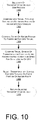
- FIG. 10 is a flow diagram illustrating an example sub-process 1000 for selecting a transportation vehicle, according to some implementations.
- the example sub-process begins with comparing an initial UAV travel path and destination to known routes of available transportation vehicles, as in 1002.
- one factor that may be considered is whether landing on a given transportation vehicle will result in a net energy savings for the UAV. For example, if a UAV must fly too far out of its way to reach a transportation vehicle, the UAV may expend more energy than it will save by landing and being transported by the transportation vehicle.
- the timing of the known routes is compared to a timeframe for the UAV travel, as in 1004.
- the travel path of the UAV may be associated with a specific timeframe, (e.g., as related to a delivery deadline). In such circumstances, if the known route has too many delays, it may cause the UAV to miss the delivery deadline, and therefore would not be an appropriate selection.
- the travel speeds of the transportation vehicles along the known routes is compared to a maximum speed for a safe landing of a UAV, as in 1006.
- a UAV may have a maximum flying speed, and if a transportation vehicle will be traveling along a portion of a route (e.g., a freeway) where the travel speed exceeds the maximum flying speed of the UAV, the UAV will not be able to keep up with and correspondingly land on transportation vehicle.
- certain speeds may be determined to be too fast (e.g., due to wind shear, turbulence, potential speed variations, etc.) to be within a desired margin of safety for a landing.
- a transportation vehicle is selected for the UAV to land on, as in 1008.
- some or all of the previously described factors may be assigned weighted values and may be included in an optimization calculation. For example, factors such as energy savings, timing, safety, etc. may all be considered as part of an evaluation for selecting a transportation vehicle.
- FIG. 11 is a flow diagram illustrating an example sub-process 1100 for landing a UAV on a transportation vehicle, according to some implementations.
- the example sub-process begins with a determination of a current estimated route location and/or a current actual location of a transportation vehicle, as in 1102. For example, GPS data may be utilized to determine a current actual location, travel speed, direction, etc. of a transportation vehicle. Once the current estimated or actual location of the transportation vehicle is determined, an estimated meeting location where the UAV will meet the transportation vehicle is planned, as in 1104. Factors for determining the estimated meeting location may include the flying speed of the UAV, the travel speed and direction of the transportation vehicle, upcoming changes in the known route of the transportation vehicle, etc.
- the UAV is instructed to fly toward the estimated meeting location, as in 1106.
- a determination is made as to whether an adjustment is needed for the meeting location, as in 1108. For example, if the actual travel speed or route of the transportation vehicle and/or UAV is different than was expected, an adjustment to the meeting location may be required. If an adjustment is needed for the meeting location, the flight path is adjusted toward the adjusted meeting location, as in 1110.
- a securing component may be utilized to secure the UAV to the transportation vehicle, as in 1114.
- securing components may be included on the UAV, the transportation vehicle, or both.
- a hooking component may be included on either the UAV or transportation vehicle, or both, for securing the UAV to the transportation vehicle.
- the UAV may include an electromagnetic securing component for securing to a roof or other surface of the transportation vehicle.
- FIG. 12 is a flow diagram illustrating an example process 1200 for communications during a landing of a UAV on a transportation vehicle, according to some implementations.
- the example process begins with an identification of a transportation vehicle, as in 1202.
- the particular transportation vehicle may be identified in accordance with a visual identifier or other identification technique.
- the transportation vehicle may include identifying markers on a roof or other surface, such as painted numbers, a barcode, a QR code, etc. that may be imaged or scanned by a flying UAV, or may transmit a coded sequence, or may otherwise be identified by GPS location, etc.
- a notification is sent regarding the landing, as in 1204.
- the notification may be sent from the UAV 400 or UAV management system 226 to the transportation vehicle and/or a management system of the transportation vehicle.
- the notification may include various types of information regarding the proposed landing.
- the notification may include an estimated arrival time and/or an estimated meeting location where the UAV will land on the transportation vehicle.
- the notification may include a request for confirmation that a landing is acceptable.
- the notification may include information for a driver of the transportation vehicle, indicating that a landing is about to occur, and may include requests such as to maintain a current speed or heading, or to remain parked while the landing occurs, etc.
- the response may include different types of information regarding the proposed landing.
- the response may include an indication as to whether or not the proposed landing is acceptable.
- a determination is made as to whether the landing is acceptable, as in 1208.
- the transportation vehicle may already have a scheduled landing planned at a short time later by another UAV, may already have another UAV on the roof, or may not currently be following a scheduled route, for which a landing may not be acceptable. If a landing is not acceptable, a reply notification is sent confirming that no landing will be attempted, as in 1210. If a landing is acceptable, a notification is sent confirming when the landing is complete, as in 1212.
- part or all of the example process 1200 may be performed when a UAV arrives at a planned meeting location (e.g., as described above with respect to FIG. 11 ), or alternatively may be performed when a UAV identifies a transportation vehicle as the UAV flies along a travel path.
- a UAV that is flying along a travel path toward a travel destination may continually scan for transportation vehicles that are travelling below and may identify transportation vehicles based on visual identifiers or other identification techniques.
- the UAV may land on the transportation vehicle for transport for as long as the transportation vehicle appears to be continuing to carry the UAV closer to the travel destination of the UAV (e.g., as determined by GPS tracking of the UAV, etc.). Once the transportation vehicle does not appear to be carrying the UAV any closer to the travel destination of the UAV, the UAV may take off from the transportation vehicle and continue flying toward the travel destination.
- FIG. 13 is a flow diagram illustrating an example process 1300 for an emergency landing on a transportation vehicle, according to some implementations.
- the example process begins with designating emergency parameters for a selection of a transportation vehicle, as in 1302.
- the emergency parameters may adjust or eliminate certain factors with regard to the selection of the transportation vehicle. For example, in a situation where the UAV has a limited ability to fly for an extended period of time (e.g., due to mechanical issues, low energy level of power module, etc.) the emergency parameters may indicate that a nearby transportation vehicle should be selected relatively quickly. In such instances, a transportation vehicle that would otherwise not be selected due to not providing any energy savings (e.g., heading in an opposite direction of a travel destination for the UAV), may be selected.
- the transportation vehicle selection sub-process is performed, as in 1000, as described above with respect to FIG. 10 .
- the flying and landing of the UAV sub-process is performed, as in 1100, as described above with respect to FIG. 11 .
- emergency post-landing procedures are executed, as in 1308.
- the emergency post-landing procedures may include communications or activities for the removal and return of the UAV. For example, a message may be sent to a management system for the transportation vehicle, indicating that an emergency landing has been performed, and outlining steps for the return of the UAV.
- an agent may be dispatched to meet the transportation vehicle at a designated location for retrieving the UAV.
- instructions may be sent for shipping the UAV back in a box, or dropping the UAV off at a designated location, etc.
- FIG. 14 is a flow diagram illustrating an example process 1400 for recording available transportation vehicles and associated routes in a database, according to some implementations.
- the example process begins with evaluating one or more available transportation vehicles (e.g., of a shipping carrier, of public transportation company, etc.).
- available transportation vehicles e.g., of a shipping carrier, of public transportation company, etc.
- different types of vehicles may have specific characteristics that may be more or less suitable with regard to the landing of UAVs.
- certain transportation vehicles may have a larger amount of space on the roof or other surface, which may be preferable for the landing of UAVs.
- an evaluation is also performed of the associated routes of the transportation vehicles.
- the associated travel ranges and timing of the routes may be important for determining when and how often the associated transportation vehicles may be selected for landings and transport of UAVs.
- a determination may be made of the compensation and associated agreement for allowing UAVs to land on the transportation vehicles, as in 1406.
- the agreement may include terms of compensation for each time a landing is performed, and/or may cover an overall agreement for the use of the transportation vehicles for landings. For example, a fixed or recurring fee may be paid to allow for landing of UAVs on transportation vehicles of a shipping carrier.
- the agreement may be made between a first entity (e.g., a company or other entity that owns the UAVs) and a second entity (e.g., a shipping carrier, a public transportation company, etc.) that owns the transportation vehicles.
- a first entity e.g., a company or other entity that owns the UAVs
- a second entity e.g., a shipping carrier, a public transportation company, etc.
- FIG. 15 is a pictorial diagram of an illustrative implementation of a server system, such as the server system 220, which may be used in the implementations described herein.
- the server system 220 may include a processor 1500, such as one or more redundant processors, a video display adapter 1502, a disk drive 1504, an input/output interface 1506, a network interface 1508, and a memory 1512.
- the processor 1500, the video display adapter 1502, the disk drive 1504, the input/output interface 1506, the network interface 1508, and the memory 1512 may be communicatively coupled to each other by a communication bus 1510.
- the video display adapter 1502 provides display signals to a local display (not shown in FIG. 15 ) permitting an agent of the server system 220 to monitor and configure operation of the server system 220 and/or to provide information (e.g., regarding a landing of a UAV 400 on a transportation vehicle 201, etc.).
- the input/output interface 1506 likewise communicates with external input/output devices not shown in FIG. 15 , such as a mouse, keyboard, scanner, or other input and output devices that can be operated by an agent of the server system 220.
- the network interface 1508 includes hardware, software, or any combination thereof, to communicate with other computing devices.
- the network interface 1508 may be configured to provide communications between the server system 220 and other computing devices, such as that of a UAV 400, UAV management system 226, transportation vehicle 201 and/or transportation vehicle management system, etc., via a network.
- the memory 1512 generally comprises random access memory (RAM), read-only memory (ROM), flash memory, and/or other volatile or permanent memory.
- RAM random access memory
- ROM read-only memory
- BIOS binary input/output system
- the memory 1512 additionally stores program code and data for providing network services to the UAV 400, UAV management system 226, transportation vehicle 201 and/or transportation vehicle management system. Accordingly, the memory 1512 may store a browser application 1518.
- the browser application 1518 comprises computer executable instructions, that, when executed by the processor 1500 generate or otherwise obtain configurable markup documents such as Web pages.
- the browser application 1518 communicates with a data store manager application 1520 to facilitate data exchange between the data store 209 and the UAV management system 226.
- the term "data store” refers to any device or combination of devices capable of storing, accessing, and retrieving data, which may include any combination and number of data servers, databases, data storage devices and data storage media, in any standard, distributed or clustered environment.
- the server system 220 can include any appropriate hardware and software for integrating with the data store 209 as needed to execute aspects of one or more applications for a UAV 400, UAV management system 226, transportation vehicle 201, and/or transportation vehicle management system.
- the memory 1512 may also include the UAV management system 226, discussed above.
- the UAV management system 226 may be executable by the processor 1500 to implement one or more of the functions of the server system 220.
- the UAV management system 226 may represent instructions embodied in one or more software programs stored in the memory 1512.
- the UAV management system 226 can represent hardware, software instructions, or a combination thereof.
- the server system 220 in one implementation, is a distributed environment utilizing several computer systems and components that are interconnected via communication links, using one or more computer networks or direct connections.
- the server system 220 could operate equally well in a system having fewer or a greater number of components than are illustrated in FIG. 15 .
- the depiction in FIG. 15 should be taken as being illustrative in nature and not limiting to the scope of the disclosure.
- Embodiments disclosed herein may include a computer implemented method to temporarily or repeatedly transport an unmanned aerial vehicle (“UAV") on a transportation vehicle including one or more of, under control of one or more computing systems configured with executable instructions, sending instructions to the UAV to take off from a departure location and begin flying toward a destination, evaluating known routes for a plurality of transportation vehicles for which one or more agreements have been made to allow for the landing of UAVs on the plurality of transportation vehicles, selecting a transportation vehicle from the plurality of transportation vehicles, and/or sending instructions to the UAV to land on the selected transportation vehicle for transport during a portion of the known route of the transportation vehicle.
- UAV unmanned aerial vehicle
- the method may comprise sending instructions to the UAV to take off from the transportation vehicle at an end of the portion of the known route and to fly toward the destination.
- the method may comprise sending a notification indicating that an emergency landing of the UAV has occurred on the transportation vehicle.
- at least one of the UAV and/or the transportation vehicle may include a securing component, and may further include utilizing the securing component to hold the UAV on the transportation vehicle while the transportation vehicle is in motion.
- the transportation vehicle may comprise at least one of a truck, an automobile, a train, an aircraft, and/or a watercraft.
- the known route of the transportation vehicle may be for transporting at least one of items or passengers.
- a first entity may own the UAV and a second entity that is different from the first entity may own the transportation vehicle.
- the method may include providing compensation to the second entity for the landing of the UAV on the selected transportation vehicle.
- Embodiments disclosed herein may include a system to utilize transportation vehicles to transport an unmanned aerial vehicle (“UAV"), the system including one or more of a propulsion system, a power module to store energy with a corresponding energy level, the power module connected to the propulsion system and configured to provide energy to the propulsion system to fly the UAV, and/or a computing system.
- the computing system may include one or more of a processor and/or a memory coupled to the processor.
- the computing system may be configured to store program instructions that when executed by the processor cause the processor to one or more of monitor an energy level of the power module, fly the UAV to land on a transportation vehicle that is traveling along a known route, and/or remain on the transportation vehicle for a portion of the known route to conserve stored energy of the power module.
- the system may further include a securing component to maintain the UAV on the transportation vehicle while the transportation vehicle is in motion.
- at least one propeller of the propulsion system may be configured to generate electricity from an airflow around the transportation vehicle while the transportation vehicle is moving.
- the transportation vehicle may further include a power source to re-charge the power module while the UAV is on the transportation vehicle.
- the program instructions that when executed by the processor to cause the processor to fly the UAV to land on the transportation vehicle, may further cause the processor to determine that the energy level of the power module is below a threshold.
- the UAV may further comprise an imaging sensor configured to one or more of determine an identification of the transportation vehicle and/or assist with landing the UAV on the transportation vehicle.
- the UAV may further include a GPS component configured to determine a location of the UAV as part of the flying of the UAV to land on the transportation vehicle.
- Embodiments disclosed herein may include a computer implemented method including one or more of, under control of one or more computing systems configured with executable instructions, evaluating a route for each of a plurality of transportation vehicles relative to a travel destination of an unmanned aerial vehicle (“UAV”), selecting a transportation vehicle to bring the UAV closer to the travel destination based at least in part on the evaluation, and/or selecting a meeting location that the UAV will fly to and land on the transportation vehicle for transport during a portion of a route of the transportation vehicle.
- UAV unmanned aerial vehicle
- the method may include estimating a departure location where the UAV will depart from the transportation vehicle and fly toward the travel destination.
- the evaluating of the route for each of the plurality of transportation vehicles may include one or more of estimating a timing of each route, and/or not selecting a second transportation vehicle based at least in part on an estimation that the timing of the route for the second transportation vehicle would not transport the UAV quickly enough to meet a delivery deadline of the UAV.
- the evaluating of the route for each of the plurality of transportation vehicles may include one or more of estimating, for a second transportation vehicle, a travel speed of the second transportation vehicle, determining, based at least in part on the estimated travel speed, that the second transportation vehicle will be moving too quickly for the UAV to safely land on the transportation vehicle, and/or not selecting the second transportation vehicle.
- the selection of the meeting location that the UAV will fly to and land on the transportation vehicle may be based at least in part on GPS information regarding a current location of the transportation vehicle.
- the landing of the UAV on the transportation vehicle may be performed as part of an emergency maneuver.
- the method may include providing compensation to an owner of the transportation vehicle for the landing of the UAV on the transportation vehicle.
- illustrated data structures may store more or less information than is described, such as when other illustrated data structures instead lack or include such information respectively, or when the amount or types of information that is stored is altered.
- the various methods and systems as illustrated in the figures and described herein represent example implementations. The methods and systems may be implemented in software, hardware, or a combination thereof in other implementations. Similarly, the order of any method may be changed and various elements may be added, reordered, combined, omitted, modified, etc., in other implementations.
Applications Claiming Priority (3)
| Application Number | Priority Date | Filing Date | Title |
|---|---|---|---|
| US14/635,743 US9809305B2 (en) | 2015-03-02 | 2015-03-02 | Landing of unmanned aerial vehicles on transportation vehicles for transport |
| EP16718931.5A EP3265383B1 (de) | 2015-03-02 | 2016-03-01 | Landung von unbemannten luftfahrzeugen auf sich bewegenden transportfahrzeugen zum transport |
| PCT/US2016/020301 WO2016140988A1 (en) | 2015-03-02 | 2016-03-01 | Landing of unmanned aerial vehicles on moving transportation vehicles for transport |
Related Parent Applications (2)
| Application Number | Title | Priority Date | Filing Date |
|---|---|---|---|
| EP16718931.5A Division EP3265383B1 (de) | 2015-03-02 | 2016-03-01 | Landung von unbemannten luftfahrzeugen auf sich bewegenden transportfahrzeugen zum transport |
| EP16718931.5A Division-Into EP3265383B1 (de) | 2015-03-02 | 2016-03-01 | Landung von unbemannten luftfahrzeugen auf sich bewegenden transportfahrzeugen zum transport |
Publications (2)
| Publication Number | Publication Date |
|---|---|
| EP3514061A1 true EP3514061A1 (de) | 2019-07-24 |
| EP3514061B1 EP3514061B1 (de) | 2021-05-26 |
Family
ID=55854780
Family Applications (2)
| Application Number | Title | Priority Date | Filing Date |
|---|---|---|---|
| EP19154613.4A Active EP3514061B1 (de) | 2015-03-02 | 2016-03-01 | Landung von unbemannten luftfahrzeugen auf transportfahrzeugen zum transport |
| EP16718931.5A Active EP3265383B1 (de) | 2015-03-02 | 2016-03-01 | Landung von unbemannten luftfahrzeugen auf sich bewegenden transportfahrzeugen zum transport |
Family Applications After (1)
| Application Number | Title | Priority Date | Filing Date |
|---|---|---|---|
| EP16718931.5A Active EP3265383B1 (de) | 2015-03-02 | 2016-03-01 | Landung von unbemannten luftfahrzeugen auf sich bewegenden transportfahrzeugen zum transport |
Country Status (6)
| Country | Link |
|---|---|
| US (2) | US9809305B2 (de) |
| EP (2) | EP3514061B1 (de) |
| JP (2) | JP6534450B2 (de) |
| CN (2) | CN107438564B (de) |
| CA (1) | CA2978177C (de) |
| WO (1) | WO2016140988A1 (de) |
Cited By (1)
| Publication number | Priority date | Publication date | Assignee | Title |
|---|---|---|---|---|
| CN114020014A (zh) * | 2021-10-27 | 2022-02-08 | 中国船舶工业系统工程研究院 | 无人机回收过程航线规划控制方法、装置、设备及介质 |
Families Citing this family (195)
| Publication number | Priority date | Publication date | Assignee | Title |
|---|---|---|---|---|
| AU2014293617A1 (en) | 2013-05-03 | 2015-12-03 | Aerovironment, Inc. | Vertical takeoff and landing (VTOL) air vehicle |
| US9704409B2 (en) * | 2014-08-05 | 2017-07-11 | Qualcomm Incorporated | Piggybacking unmanned aerial vehicle |
| WO2016130716A2 (en) | 2015-02-11 | 2016-08-18 | Aerovironment, Inc. | Geographic survey system for vertical take-off and landing (vtol) unmanned aerial vehicles (uavs) |
| US10850866B2 (en) * | 2015-02-11 | 2020-12-01 | Aerovironment, Inc. | Pod cover system for a vertical take-off and landing (VTOL) unmanned aerial vehicle (UAV) |
| US10336470B2 (en) | 2015-02-11 | 2019-07-02 | Aerovironment, Inc. | Pod launch and landing system for vertical take-off and landing (VTOL)unmanned aerial vehicles (UAVs) |
| US11021266B2 (en) | 2015-02-11 | 2021-06-01 | Aerovironment, Inc. | Pod operating system for a vertical take-off and landing (VTOL) unmanned aerial vehicle (UAV) |
| US9977435B2 (en) | 2015-02-11 | 2018-05-22 | Aeroviroment, Inc. | Survey migration system for vertical take-off and landing (VTOL) unmanned aerial vehicles (UAVS) |
| US20180099846A1 (en) | 2015-03-06 | 2018-04-12 | Wal-Mart Stores, Inc. | Method and apparatus for transporting a plurality of stacked motorized transport units |
| US9534906B2 (en) | 2015-03-06 | 2017-01-03 | Wal-Mart Stores, Inc. | Shopping space mapping systems, devices and methods |
| WO2016142794A1 (en) | 2015-03-06 | 2016-09-15 | Wal-Mart Stores, Inc | Item monitoring system and method |
| US10867277B2 (en) | 2015-07-08 | 2020-12-15 | Ebay Inc. | Public transport infrastructure facilitated drone delivery |
| CA2999486A1 (en) | 2015-09-23 | 2017-03-30 | Walmart Apollo, Llc | Package release system for use in delivery packages, and methods of delivering packages |
| CA2999172A1 (en) | 2015-09-23 | 2017-03-30 | Walmart Apollo, Llc | Portable unmanned delivery aircraft launch systems, and methods of delivering products utilizing aircraft launch systems |
| GB2556843B (en) | 2015-09-23 | 2021-05-19 | Walmart Apollo Llc | Systems and methods of delivering products with unmanned delivery aircrafts |
| WO2017068871A1 (ja) * | 2015-10-21 | 2017-04-27 | ソニー株式会社 | 情報処理装置、情報処理方法及び輸送システム |
| US11091275B2 (en) * | 2015-10-22 | 2021-08-17 | Droneovation, Inc. | Aerial drone operations support base |
| MX2018005328A (es) | 2015-10-27 | 2018-09-21 | Walmart Apollo Llc | Metodo y aparato para una ruta de entrenamiento de dron aereo. |
| KR101727516B1 (ko) * | 2015-10-28 | 2017-04-17 | 고현승 | 무인배송기기를 이용한 물품 배송 방법 |
| MX2018005697A (es) | 2015-11-06 | 2018-11-09 | Walmart Apollo Llc | Metodo y aparato para despachar un dron aereo para transportar un articulo a un consumidor. |
| GB2558497A (en) | 2015-11-06 | 2018-07-11 | Walmart Apollo Llc | Targeted location product delivery systems and methods |
| WO2017083406A1 (en) * | 2015-11-10 | 2017-05-18 | Matternet, Inc. | Methods and systems for transportation using unmanned aerial vehicles |
| US20170129602A1 (en) * | 2015-11-10 | 2017-05-11 | M3N, Inc. | Multipurpose Robotic System |
| US10592843B2 (en) * | 2015-11-25 | 2020-03-17 | Walmart Apollo, Llc | Unmanned aerial delivery to secure location |
| GB2564965B (en) | 2015-12-16 | 2021-06-16 | Walmart Apollo Llc | Systems and methods of capturing and distributing imaging content captured through unmanned aircraft systems |
| CA2952098A1 (en) | 2015-12-18 | 2017-06-18 | Wal-Mart Stores, Inc. | Apparatus and method for surveying premises of a customer |
| US10403153B2 (en) * | 2016-01-05 | 2019-09-03 | United States Of America As Represented By The Administrator Of Nasa | Autonomous emergency flight management system for an unmanned aerial system |
| US11095129B2 (en) * | 2016-02-12 | 2021-08-17 | Capacitor Sciences Incorporated | Capacitor based power system and unmanned vehicle with the capacitor based power system thereof |
| GB2570411B (en) * | 2016-02-12 | 2020-01-22 | Walmart Apollo Llc | Gas-filled carrier aircrafts and methods of dispersing unmanned aircraft systems in delivering products |
| JP2019512419A (ja) | 2016-03-02 | 2019-05-16 | ウォルマート アポロ,エルエルシー | 顧客インターフェースシステムを備える無人航空機システム及び無人航空機システムを利用する配送方法 |
| US10062292B2 (en) | 2016-03-08 | 2018-08-28 | International Business Machines Corporation | Programming language for execution by drone |
| US10417917B2 (en) | 2016-03-08 | 2019-09-17 | International Business Machines Corporation | Drone management data structure |
| US9950791B2 (en) * | 2016-03-08 | 2018-04-24 | International Business Machines Corporation | Drone receiver |
| US9852642B2 (en) | 2016-03-08 | 2017-12-26 | International Business Machines Corporation | Drone air traffic control and flight plan management |
| US10246186B1 (en) * | 2016-03-09 | 2019-04-02 | Amazon Technologies, Inc. | Unmanned aerial vehicle with inflatable membrane |
| WO2017180270A2 (en) | 2016-03-14 | 2017-10-19 | Wal-Mart Stores, Inc. | Unmanned aircraft systems and methods to interact with specifically intended objects |
| WO2017160790A1 (en) | 2016-03-18 | 2017-09-21 | Wal-Mart Stores, Inc. | Unmanned aircraft systems and methods |
| US10553122B1 (en) * | 2016-03-22 | 2020-02-04 | Amazon Technologies, Inc. | Unmanned aerial vehicle data collection for routing |
| WO2017165379A1 (en) | 2016-03-25 | 2017-09-28 | Wal-Mart Stores, Inc. | Unmanned aircraft systems and methods of assembly |
| US20170286887A1 (en) * | 2016-03-31 | 2017-10-05 | Avaya Inc. | Systems and methods for allocating agent resources in a contact center |
| GB2564335A (en) | 2016-03-31 | 2019-01-09 | Walmart Apollo Llc | Apparatus and method for providing aerial animal food delivery |
| CA2961938A1 (en) | 2016-04-01 | 2017-10-01 | Wal-Mart Stores, Inc. | Systems and methods for moving pallets via unmanned motorized unit-guided forklifts |
| US10457393B2 (en) * | 2016-04-05 | 2019-10-29 | Walmart Apollo, Llc | Apparatuses and methods for receiving aerial vehicle delivery |
| US9969495B2 (en) | 2016-04-29 | 2018-05-15 | United Parcel Service Of America, Inc. | Unmanned aerial vehicle pick-up and delivery systems |
| US10730626B2 (en) | 2016-04-29 | 2020-08-04 | United Parcel Service Of America, Inc. | Methods of photo matching and photo confirmation for parcel pickup and delivery |
| GB2564804B (en) | 2016-05-04 | 2021-04-21 | Walmart Apollo Llc | Systems and methods for transporting products via unmanned aerial vehicles |
| US10040552B2 (en) * | 2016-05-06 | 2018-08-07 | International Business Machines Corporation | Alert system for an unmanned aerial vehicle |
| US10737765B2 (en) | 2016-07-01 | 2020-08-11 | Textron Innovations Inc. | Aircraft having single-axis gimbal mounted propulsion systems |
| WO2018013322A1 (en) | 2016-07-12 | 2018-01-18 | Wal-Mart Stores, Inc. | Systems and methods for automated assessment of physical objects |
| US10216188B2 (en) | 2016-07-25 | 2019-02-26 | Amazon Technologies, Inc. | Autonomous ground vehicles based at delivery locations |
| US10562432B2 (en) * | 2016-08-01 | 2020-02-18 | Toyota Motor Engineering & Manufacturing North America, Inc. | Vehicle docking and control systems for robots |
| US11880784B2 (en) * | 2016-08-05 | 2024-01-23 | Starship Technologies Oü | System and mobile freight station and method for distribution, delivery, and collection of freight |
| US10275975B2 (en) | 2016-08-19 | 2019-04-30 | Walmart Apollo, Llc | Apparatus and method for mobile vending |
| MX2019002644A (es) | 2016-09-08 | 2019-06-17 | Walmart Apollo Llc | Sistemas y metodos para dispensar un insecticida a traves de vehiculos no tripulados para defender un area que contiene cultivo contra plagas. |
| MX2019002613A (es) | 2016-09-08 | 2019-07-10 | Walmart Apollo Llc | Metodos y sistema automatizado de encaminamiento de cajas. |
| US10445791B2 (en) | 2016-09-08 | 2019-10-15 | Walmart Apollo, Llc | Systems and methods for autonomous assistance and routing |
| GB2573228B (en) | 2016-09-09 | 2020-04-29 | Walmart Apollo Llc | Systems and methods to interchangeably couple tool systems with unmanned vehicles |
| GB2568421A (en) * | 2016-09-09 | 2019-05-15 | Walmart Apollo Llc | Apparatus and method for unmanned flight task optimization |
| CN109963781A (zh) | 2016-09-09 | 2019-07-02 | 沃尔玛阿波罗有限责任公司 | 用于无人驾驶飞行的装置和方法 |
| GB2568191A (en) | 2016-09-09 | 2019-05-08 | Walmart Apollo Llc | Geographic area monitoring systems and methods through interchanging tool systems between unmanned vehicles |
| CA3035762A1 (en) | 2016-09-09 | 2018-03-15 | Walmart Apollo, Llc | Geographic area monitoring systems and methods that balance power usage between multiple unmanned vehicles |
| CN109997116A (zh) | 2016-09-09 | 2019-07-09 | 沃尔玛阿波罗有限责任公司 | 用于监视现场的装置和方法 |
| WO2018057315A2 (en) * | 2016-09-09 | 2018-03-29 | Wal-Mart Stores, Inc. | Geographic area monitoring systems and methods utilizing computational sharing across multiple unmanned vehicles |
| JP2018045643A (ja) * | 2016-09-16 | 2018-03-22 | シャープ株式会社 | 無人航空機制御システム、サーバ装置、標識提示装置、及び無人航空機 |
| US10248120B1 (en) | 2016-09-16 | 2019-04-02 | Amazon Technologies, Inc. | Navigable path networks for autonomous vehicles |
| US20180086452A1 (en) * | 2016-09-28 | 2018-03-29 | Intel Corporation | Drone-carrier brokering |
| US10303171B1 (en) | 2016-09-29 | 2019-05-28 | Amazon Technologies, Inc. | Autonomous ground vehicles providing ordered items in pickup areas |
| US10222798B1 (en) | 2016-09-29 | 2019-03-05 | Amazon Technologies, Inc. | Autonomous ground vehicles congregating in meeting areas |
| US10241516B1 (en) | 2016-09-29 | 2019-03-26 | Amazon Technologies, Inc. | Autonomous ground vehicles deployed from facilities |
| US10245993B1 (en) | 2016-09-29 | 2019-04-02 | Amazon Technologies, Inc. | Modular autonomous ground vehicles |
| CA3036706A1 (en) | 2016-10-04 | 2018-04-12 | Walmart Apollo, Llc | Landing pad receptacle for package delivery and receipt |
| WO2018067768A1 (en) | 2016-10-06 | 2018-04-12 | Wal-Mart Stores, Inc. | Systems and methods to communicate with persons of interest |
| WO2018065977A1 (en) * | 2016-10-07 | 2018-04-12 | Shmuel Ur Innovation Ltd. | Drone based delivery system using vehicles |
| US20200286034A1 (en) * | 2017-09-25 | 2020-09-10 | Shmuel Ur Innovation Ltd | Drone based delivery system using vehicles |
| US10353388B2 (en) * | 2016-10-17 | 2019-07-16 | X Development Llc | Drop-off location planning for delivery vehicle |
| US10839699B2 (en) * | 2016-10-18 | 2020-11-17 | International Business Machines Corporation | Methods and systems for managing aerial drones in regulated spaces with ground vehicle assist |
| US10233021B1 (en) | 2016-11-02 | 2019-03-19 | Amazon Technologies, Inc. | Autonomous vehicles for delivery and safety |
| US10254766B2 (en) | 2016-11-09 | 2019-04-09 | Walmart Apollo, Llc | Autonomous ganged vehicles |
| US20180130159A1 (en) | 2016-11-10 | 2018-05-10 | Wal-Mart Stores, Inc. | Systems and methods for delivering products via autonomous ground vehicles to restricted areas designated by customers |
| US10620011B2 (en) * | 2016-11-10 | 2020-04-14 | International Business Machines Corporation | Autonomous vehicle routing |
| US10514690B1 (en) | 2016-11-15 | 2019-12-24 | Amazon Technologies, Inc. | Cooperative autonomous aerial and ground vehicles for item delivery |
| US10198708B2 (en) | 2016-11-16 | 2019-02-05 | Walmart Apollo, Llc | Systems and methods for enabling delivery of commercial products to customers |
| US10120383B2 (en) | 2016-11-16 | 2018-11-06 | Walmart Apollo, Llc | Systems and methods to deter theft of commercial products |
| US11068837B2 (en) * | 2016-11-21 | 2021-07-20 | International Business Machines Corporation | System and method of securely sending and receiving packages via drones |
| US10562398B2 (en) | 2016-11-22 | 2020-02-18 | Walmart Apollo, Llc | System and method for autonomous battery replacement |
| US10571225B2 (en) | 2016-11-22 | 2020-02-25 | Walmart Apollo, Llc | System and method for camouflaging and recharging autonomous vehicles |
| CN107004177B (zh) * | 2016-11-22 | 2024-03-19 | 达闼机器人股份有限公司 | 提升无人机运输安全的方法、无人机、终端、服务器和计算机程序产品 |
| US10120376B2 (en) * | 2016-11-30 | 2018-11-06 | International Business Machines Corporation | Renewable UAV energy via blade rotation |
| MX2019006371A (es) | 2016-12-01 | 2019-12-05 | Walmart Apollo Llc | Dron autonomo y seleccion de herramientas y entrega. |
| US11263579B1 (en) | 2016-12-05 | 2022-03-01 | Amazon Technologies, Inc. | Autonomous vehicle networks |
| MX2019006786A (es) | 2016-12-12 | 2019-10-30 | Walmart Apollo Llc | Sistemas y metodos para entregar productos a traves de vehiculos terrestres autonomos a vehiculos designados por los clientes. |
| KR20180068469A (ko) * | 2016-12-14 | 2018-06-22 | 현대자동차주식회사 | 무인비행장치 및 이를 포함하는 시스템 |
| US10717524B1 (en) * | 2016-12-20 | 2020-07-21 | Amazon Technologies, Inc. | Unmanned aerial vehicle configuration and deployment |
| GB2575553B (en) | 2016-12-21 | 2022-01-12 | Walmart Apollo Llc | Autonomous locker delivery |
| US10308430B1 (en) | 2016-12-23 | 2019-06-04 | Amazon Technologies, Inc. | Distribution and retrieval of inventory and materials using autonomous vehicles |
| US10310499B1 (en) | 2016-12-23 | 2019-06-04 | Amazon Technologies, Inc. | Distributed production of items from locally sourced materials using autonomous vehicles |
| US10310500B1 (en) | 2016-12-23 | 2019-06-04 | Amazon Technologies, Inc. | Automated access to secure facilities using autonomous vehicles |
| WO2018132647A1 (en) | 2017-01-13 | 2018-07-19 | Wal-Mart Stores, Inc. | Electronic communications in connection with a package delivery |
| CN106774221A (zh) * | 2017-01-22 | 2017-05-31 | 江苏中科院智能科学技术应用研究院 | 一种无人机与无人车协作巡逻系统及方法 |
| US10079497B2 (en) * | 2017-01-25 | 2018-09-18 | Coretronic Intelligent Robotics Corporation | Charge device for a drone |
| WO2018151712A1 (en) * | 2017-02-15 | 2018-08-23 | Ford Global Technologies, Llc | Aerial vehicle-ground vehicle coordination |
| GB2560000B (en) * | 2017-02-24 | 2021-06-09 | Roke Manor Res Limited | A coupling mechanism for light vehicles |
| JP6521042B2 (ja) * | 2017-02-24 | 2019-05-29 | キヤノンマーケティングジャパン株式会社 | 情報処理装置、情報処理装置の制御方法、無人航空機、無人航空機の制御方法、およびプログラム |
| US10421542B2 (en) * | 2017-03-16 | 2019-09-24 | Amazon Technologies, Inc. | Mobile fulfillment centers with intermodal carriers and unmanned aerial vehicles |
| US10384692B2 (en) * | 2017-03-16 | 2019-08-20 | Amazon Technologies, Inc. | Demand-based distribution of items using intermodal carriers and unmanned aerial vehicles |
| US10147249B1 (en) | 2017-03-22 | 2018-12-04 | Amazon Technologies, Inc. | Personal intermediary communication device |
| US10573106B1 (en) | 2017-03-22 | 2020-02-25 | Amazon Technologies, Inc. | Personal intermediary access device |
| JP6624139B2 (ja) * | 2017-03-24 | 2019-12-25 | カシオ計算機株式会社 | 自律移動装置、自律移動方法及びプログラム |
| JP6772100B2 (ja) * | 2017-03-28 | 2020-10-21 | 株式会社ゼンリンデータコム | ドローン用動態管理装置、ドローン用動態管理方法及びドローン用動態管理プログラム |
| WO2018183428A1 (en) | 2017-03-31 | 2018-10-04 | Walmart Apollo, Llc | Contact activated retail delivery package release systems and methods |
| WO2018183431A1 (en) | 2017-03-31 | 2018-10-04 | Walmart Apollo, Llc | Retail delivery packages and methods of product delivery |
| US10450091B2 (en) * | 2017-04-07 | 2019-10-22 | DroneTerminus LLC | Package acceptance, guidance, and refuel system for drone technology |
| US20180300834A1 (en) | 2017-04-17 | 2018-10-18 | Walmart Apollo, Llc | Systems and methods for delivering merchandise using autonomous ground vehicles and unmanned aerial vehicles |
| US10467578B2 (en) * | 2017-05-08 | 2019-11-05 | Wing Aviation Llc | Methods and systems for requesting and displaying UAV information |
| WO2018209319A1 (en) | 2017-05-12 | 2018-11-15 | Gencore Candeo, Ltd. | Systems and methods for response to emergency situations using unmanned airborne vehicles with improved functionalities |
| WO2018222411A1 (en) | 2017-05-31 | 2018-12-06 | Walmart Apollo, Llc | Systems and methods for delivering climate controlled product |
| US10775792B2 (en) | 2017-06-13 | 2020-09-15 | United Parcel Service Of America, Inc. | Autonomously delivering items to corresponding delivery locations proximate a delivery route |
| US20200117217A1 (en) * | 2017-06-13 | 2020-04-16 | Honda Motor Co., Ltd. | Delivery system and method, and delivery processing device |
| US10332407B2 (en) | 2017-07-07 | 2019-06-25 | Walmart Apollo, Llc | Systems and methods for providing emergency alerts at emergency landing areas of unmanned aerial vehicles |
| US20190009904A1 (en) * | 2017-07-07 | 2019-01-10 | Walmart Apollo, Llc | Systems and methods for facilitating safe emergency landings of unmanned aerial vehicles |
| WO2019018337A1 (en) | 2017-07-20 | 2019-01-24 | Walmart Apollo, Llc | TASK MANAGEMENT OF AUTONOMOUS PRODUCT DELIVERY VEHICLES |
| US20190025818A1 (en) * | 2017-07-21 | 2019-01-24 | Walmart Apollo, Llc | Autonomous product delivery vehicle fleet master-slave relationship management |
| CN107506959A (zh) * | 2017-07-24 | 2017-12-22 | 杭州王道控股有限公司 | 基于搭乘车辆的无人机物流方法及装置 |
| US20190043000A1 (en) * | 2017-08-01 | 2019-02-07 | Moxa Inc. | System for pairing uav and truck to make uav complete goods delivey and method thereof |
| US10916151B2 (en) * | 2017-08-02 | 2021-02-09 | Microsoft Technology Licensing, Llc | En route product delivery by unmanned aerial vehicles |
| US10600327B2 (en) * | 2017-08-07 | 2020-03-24 | Fujitsu Limited | Unmanned aircraft transportation |
| CN107392547A (zh) * | 2017-08-08 | 2017-11-24 | 北京京东尚科信息技术有限公司 | 货物运送方法、装置、系统和计算机可读存储介质 |
| WO2019036425A1 (en) * | 2017-08-17 | 2019-02-21 | Walmart Apollo, Llc | SYSTEMS AND METHODS FOR DELIVERY OF RETAIL ITEMS |
| US10535036B2 (en) | 2017-08-25 | 2020-01-14 | Walmart Apollo, Llc | Systems and methods for delivering products to a customer via another customer and an autonomous transport vehicle |
| US10585439B2 (en) * | 2017-08-29 | 2020-03-10 | Ford Global Technologies, Llc | Vehicle inspection |
| CN107627945B (zh) * | 2017-08-31 | 2020-06-05 | 浙江吉利控股集团有限公司 | 飞行汽车系统及飞行汽车共享方法 |
| US11222299B1 (en) | 2017-08-31 | 2022-01-11 | Amazon Technologies, Inc. | Indoor deliveries by autonomous vehicles |
| JP6993816B2 (ja) * | 2017-09-04 | 2022-01-14 | 株式会社日立システムズ | 自律飛行移動体、自律飛行移動方法 |
| CN107820585B (zh) * | 2017-09-06 | 2021-08-13 | 深圳市道通智能航空技术股份有限公司 | 飞行器降落方法、飞行器和计算机可读存储介质 |
| US20190114564A1 (en) * | 2017-10-18 | 2019-04-18 | United Parcel Service Of America, Inc. | Enriched Logistics System for Unmanned Vehicle Delivery of Parcels |
| US10580311B2 (en) * | 2017-10-26 | 2020-03-03 | Wing Aviation Llc | UAV group charging based on demand for UAV service |
| CN109795835B (zh) * | 2017-11-17 | 2021-04-13 | 山东新北洋信息技术股份有限公司 | 储物盒、智能物流柜及智能物流柜的控制方法 |
| US11514803B2 (en) * | 2017-12-01 | 2022-11-29 | Ford Global Technologies, Llc | Method and apparatus for vehicle to drone interaction |
| US10894601B2 (en) * | 2017-12-20 | 2021-01-19 | Wing Aviation Llc | Methods and systems for self-deployment of operational infrastructure by an unmanned aerial vehicle (UAV) |
| US11010851B2 (en) * | 2017-12-22 | 2021-05-18 | Wing Aviation Llc | Distribution of aerial vehicle transport capacity based on item-provider performance metrics |
| CN108319233A (zh) * | 2017-12-28 | 2018-07-24 | 翁振瀛 | 利用空中移动载具的物品运送系统及方法 |
| JP7034721B2 (ja) * | 2018-01-10 | 2022-03-14 | アルパイン株式会社 | 無人輸送機の制御装置及び制御方法 |
| JP7027913B2 (ja) * | 2018-01-30 | 2022-03-02 | トヨタ自動車株式会社 | ドローン管理システム、及び、ドローン管理方法 |
| KR102643528B1 (ko) * | 2018-02-08 | 2024-03-06 | 현대자동차주식회사 | 무인비행장치, 이를 포함하는 시스템 및 무인비행장치의 이동 경로 탐색방법 |
| JP2019151149A (ja) * | 2018-02-28 | 2019-09-12 | 本田技研工業株式会社 | 飛行制御装置、プログラム及び車両 |
| DE102018204205A1 (de) * | 2018-03-20 | 2019-09-26 | Ford Global Technologies, Llc | System und Verfahren zur Zustellung von Waren von einem Startpunkt zu einem Zielpunkt mittels Drohnen |
| US11148805B2 (en) * | 2018-04-10 | 2021-10-19 | Government Of The United States, As Represented By The Secretary Of The Army | Enclosure for an unmanned aerial system |
| US10894593B2 (en) * | 2018-04-27 | 2021-01-19 | Wing Aviation Llc | UAV with frangible airframe structures |
| US11410114B2 (en) | 2018-05-01 | 2022-08-09 | Wing Aviation Llc | Delivery of temperature-sensitive items |
| JP7018820B2 (ja) * | 2018-05-17 | 2022-02-14 | 東芝テック株式会社 | 情報提示装置、情報提示システムおよびプログラム |
| US20190392716A1 (en) * | 2018-06-26 | 2019-12-26 | Toyota Jidosha Kabushiki Kaisha | Assisting flying drones to select and approach vehicles for improved flying range |
| US11634220B2 (en) * | 2018-08-06 | 2023-04-25 | At&T Intellectual Property I, L.P. | Autonomous aerial management as a service |
| US10836487B2 (en) * | 2018-11-26 | 2020-11-17 | Category, LLC | System for unassisted sky diving |
| JP7159822B2 (ja) | 2018-11-29 | 2022-10-25 | トヨタ自動車株式会社 | 配送システム及び処理サーバ |
| JP6527299B1 (ja) * | 2018-12-07 | 2019-06-05 | 楽天株式会社 | 物品受け渡し場所の決定方法、着陸場所の決定方法、物品受け渡しシステム、及び情報処理装置 |
| US11392130B1 (en) | 2018-12-12 | 2022-07-19 | Amazon Technologies, Inc. | Selecting delivery modes and delivery areas using autonomous ground vehicles |
| KR20200075330A (ko) * | 2018-12-18 | 2020-06-26 | 현대자동차주식회사 | 무인비행장치를 포함하는 시스템 및 시스템의 협업 방법 |
| JP7076366B2 (ja) * | 2018-12-25 | 2022-05-27 | トッパン・フォームズ株式会社 | Rfid読取システム |
| JP7076365B2 (ja) * | 2018-12-25 | 2022-05-27 | トッパン・フォームズ株式会社 | Rfid読取システム |
| WO2020136844A1 (ja) * | 2018-12-27 | 2020-07-02 | 楽天株式会社 | 情報処理装置、方法、及び、プログラム |
| CN111121782B (zh) * | 2018-12-28 | 2023-07-04 | 中国人民解放军国防科技大学 | 车载无人机电力巡检的双层路径规划方法与装置 |
| CN109573035A (zh) * | 2018-12-31 | 2019-04-05 | 陈雨彤 | 一种无人机与私家车共享运力资源的快递投送系统 |
| WO2020209915A2 (en) * | 2019-01-15 | 2020-10-15 | Planck Aerosystems Inc. | Systems and methods for delivery using unmanned aerial vehicles |
| JP7199648B2 (ja) * | 2019-01-21 | 2023-01-06 | 株式会社ナイルワークス | ドローンシステム、ドローン、移動体、動作決定装置、ドローンシステムの制御方法、および、ドローンシステム制御プログラム |
| JP7199505B2 (ja) * | 2019-02-25 | 2023-01-05 | 株式会社日立ハイテク | 医材搬送システム |
| CN109814598B (zh) * | 2019-02-25 | 2021-02-19 | 中国科学院地理科学与资源研究所 | 无人机低空公共航路网设计方法 |
| US11620608B2 (en) | 2019-02-28 | 2023-04-04 | Walmart Apollo, Llc | System and method for providing uniform tracking information with a reliable estimated time of arrival |
| JPWO2020179195A1 (ja) * | 2019-03-06 | 2021-12-16 | Necソリューションイノベータ株式会社 | 制御装置、制御方法及び制御プログラム |
| WO2020227381A1 (en) * | 2019-05-07 | 2020-11-12 | Autonomous Shelf, Inc. | Systems, methods, computing platforms, and storage media for directing and controlling an autonomous inventory management system |
| JP6637209B1 (ja) * | 2019-05-08 | 2020-01-29 | 楽天株式会社 | 制御方法、物品受け渡しシステム、着陸システム、及び情報処理装置 |
| US11513537B2 (en) * | 2019-05-09 | 2022-11-29 | Toyota Motor Eng & Mfg North America, Inc. | Managing drones in vehicular system |
| CN112015197B (zh) * | 2019-05-28 | 2022-09-06 | 北京京东尚科信息技术有限公司 | 无人机搭乘路线处理方法、装置、设备及可读存储介质 |
| US11565807B1 (en) * | 2019-06-05 | 2023-01-31 | Gal Zuckerman | Systems and methods facilitating street-level interactions between flying drones and on-road vehicles |
| US11580613B2 (en) | 2019-06-28 | 2023-02-14 | Light Line Delivery Corp. | Parcel conveyance system |
| CN110308723A (zh) * | 2019-06-28 | 2019-10-08 | 长城汽车股份有限公司 | 飞行车辆系统 |
| US11474530B1 (en) | 2019-08-15 | 2022-10-18 | Amazon Technologies, Inc. | Semantic navigation of autonomous ground vehicles |
| JP7451112B2 (ja) * | 2019-09-05 | 2024-03-18 | キヤノン株式会社 | ドローン移動システム、およびそれを用いた配送システム |
| CN110852554B (zh) * | 2019-09-20 | 2022-03-22 | 合肥工业大学 | 车机协同下无人机任务分配智能决策方法及装置 |
| US10796562B1 (en) | 2019-09-26 | 2020-10-06 | Amazon Technologies, Inc. | Autonomous home security devices |
| US11260970B2 (en) | 2019-09-26 | 2022-03-01 | Amazon Technologies, Inc. | Autonomous home security devices |
| CN110782086B (zh) * | 2019-10-24 | 2022-09-09 | 山东师范大学 | 一种用于救援的带无人机车辆配送路径优化方法及系统 |
| CN112534377B (zh) * | 2019-11-29 | 2022-01-25 | 深圳市大疆创新科技有限公司 | 数据处理方法、无人机和计算机可读存储介质 |
| US11820511B2 (en) | 2019-12-03 | 2023-11-21 | The Boeing Company | Unmanned aerial vehicle and associated method for reducing drag during flight of an unmanned aerial vehicle |
| CN110888458B (zh) * | 2019-12-31 | 2021-07-20 | 广州极飞科技股份有限公司 | 无人机飞行控制方法、无人机、系统及存储介质 |
| CN111190434A (zh) * | 2019-12-31 | 2020-05-22 | 广州极飞科技有限公司 | 无人机搭载公交车控制方法、无人机、系统及存储介质 |
| CN111766892B (zh) * | 2019-12-31 | 2021-02-19 | 广州极飞科技有限公司 | 无人机路线规划方法、无人机、系统及存储介质 |
| WO2021183496A1 (en) | 2020-03-09 | 2021-09-16 | Autonomous Shelf, Inc. | Autonomous mobile inventory transport unit |
| US11651308B1 (en) * | 2020-04-10 | 2023-05-16 | Nuro, Inc. | Methods and apparatus for providing teleoperations functionality in a distributed manner |
| US11475778B1 (en) | 2020-05-01 | 2022-10-18 | Express Scripts Strategic Development, Inc. | System and method for secure delivery of a medication package |
| JP7068386B2 (ja) * | 2020-06-10 | 2022-05-16 | ソフトバンク株式会社 | 管理装置、プログラム、システム、及び方法 |
| KR20220044028A (ko) * | 2020-09-29 | 2022-04-06 | 현대자동차주식회사 | 드론을 이용한 배송 시스템 및 배송 방법 |
| JP7083010B2 (ja) * | 2020-09-30 | 2022-06-09 | 株式会社ゼンリンデータコム | 運航計画作成装置、運航計画作成方法および運航計画作成プログラム |
| CN113671945A (zh) * | 2021-07-15 | 2021-11-19 | 深圳市雄帝科技股份有限公司 | 无人运送车调度管理方法及其管理系统 |
| KR20230028637A (ko) * | 2021-08-19 | 2023-03-02 | 현대모비스 주식회사 | 전기 비행체의 배터리를 충전 및 방전하기 위한 방법 |
| CN113865556B (zh) * | 2021-09-23 | 2024-02-02 | 长安大学 | 一种分体式全景智能探测机器人及方法 |
| CN114620243B (zh) * | 2022-05-12 | 2022-09-06 | 四川腾盾科技有限公司 | 一种飞行器智能起降捕获系统 |
Citations (6)
| Publication number | Priority date | Publication date | Assignee | Title |
|---|---|---|---|---|
| WO2005123502A2 (en) * | 2003-12-12 | 2005-12-29 | Advanced Ceramics Research, Inc. | Unmanned vehicle |
| US20110035149A1 (en) * | 2009-07-06 | 2011-02-10 | Honeywell International Inc. | Flight technical control management for an unmanned aerial vehicle |
| US20110264311A1 (en) * | 2010-04-26 | 2011-10-27 | Hon Hai Precision Industry Co., Ltd. | Unmanned aerial vehicle and method for collecting video using the same |
| EP2722636A1 (de) * | 2012-10-22 | 2014-04-23 | The Boeing Company | Wassergebietsverwaltungssystem |
| EP2727835A2 (de) * | 2012-10-30 | 2014-05-07 | The Boeing Company | Flugzeugeinsatz- und Wiedergewinnung von unbemannten Luftfahrzeugen |
| WO2015026018A1 (ko) * | 2013-08-23 | 2015-02-26 | 한국항공우주연구원 | 무인 수직이착륙 비행체의 충전 및 격납을 위한 장치 및 그 방법 |
Family Cites Families (46)
| Publication number | Priority date | Publication date | Assignee | Title |
|---|---|---|---|---|
| US5995898A (en) * | 1996-12-06 | 1999-11-30 | Micron Communication, Inc. | RFID system in communication with vehicle on-board computer |
| US7339993B1 (en) | 1999-10-01 | 2008-03-04 | Vidiator Enterprises Inc. | Methods for transforming streaming video data |
| JP2002166895A (ja) * | 2000-12-01 | 2002-06-11 | Yamaha Motor Co Ltd | 無人ヘリコプターの燃料供給装置 |
| US20020156645A1 (en) | 2001-01-31 | 2002-10-24 | Hansen Paul E. | Network-based solution for secure parcel delivery and pick-up |
| JP2003081437A (ja) * | 2001-09-17 | 2003-03-19 | Toyota Industries Corp | 配送システム |
| US20140254896A1 (en) * | 2011-07-18 | 2014-09-11 | Tiger T G Zhou | Unmanned drone, robot system for delivering mail, goods, humanoid security, crisis negotiation, mobile payments, smart humanoid mailbox and wearable personal exoskeleton heavy load flying machine |
| JP2006051893A (ja) * | 2004-08-12 | 2006-02-23 | Seiko Epson Corp | 位置・姿勢検出システム |
| US7946530B1 (en) | 2005-06-13 | 2011-05-24 | Talmage Jr Robert N | Modular adaptive configured helicopter |
| US9373149B2 (en) | 2006-03-17 | 2016-06-21 | Fatdoor, Inc. | Autonomous neighborhood vehicle commerce network and community |
| JP2007302431A (ja) * | 2006-05-12 | 2007-11-22 | Seiko Epson Corp | 配送管理システム、配送管理サーバ装置、配送管理方法、配送管理プログラム、及び記録媒体 |
| US7673831B2 (en) | 2006-06-08 | 2010-03-09 | Lockheed Martin Corporation | Small unmanned air vehicle system for deploying and towing a sensor in a tow medium and methods related thereto |
| US8245980B2 (en) * | 2006-09-28 | 2012-08-21 | Israel Aerospace Industries Ltd. | System and method for transferring airplanes |
| US20140149244A1 (en) | 2006-11-22 | 2014-05-29 | Raj Abhyanker | Demand aggregation to enable efficient neighborhood delivery |
| WO2008147681A2 (en) * | 2007-05-10 | 2008-12-04 | Arlton Paul E | Uav launch and recovery system |
| US8060270B2 (en) * | 2008-02-29 | 2011-11-15 | The Boeing Company | System and method for inspection of structures and objects by swarm of remote unmanned vehicles |
| US8162256B2 (en) * | 2008-03-19 | 2012-04-24 | Honeywell International Inc. | Launch and capture systems for vertical take-off and landing (VTOL) vehicles |
| US8511606B1 (en) * | 2009-12-09 | 2013-08-20 | The Boeing Company | Unmanned aerial vehicle base station |
| US8862288B2 (en) * | 2010-05-18 | 2014-10-14 | The Boeing Company | Vehicle base station |
| PT2551198E (pt) | 2011-07-29 | 2013-12-27 | Agustawestland Spa | Avião convertível |
| US9381916B1 (en) | 2012-02-06 | 2016-07-05 | Google Inc. | System and method for predicting behaviors of detected objects through environment representation |
| US9384668B2 (en) * | 2012-05-09 | 2016-07-05 | Singularity University | Transportation using network of unmanned aerial vehicles |
| IL219836A (en) * | 2012-05-16 | 2017-02-28 | Meir Yoffe | Landing and spotting of unmanned aerial vehicles |
| US9051043B1 (en) | 2012-12-28 | 2015-06-09 | Google Inc. | Providing emergency medical services using unmanned aerial vehicles |
| US10551851B2 (en) | 2013-07-01 | 2020-02-04 | Steven Sounyoung Yu | Autonomous unmanned road vehicle for making deliveries |
| US9577445B2 (en) * | 2013-09-09 | 2017-02-21 | Olaeris, Inc. | Vehicle replenishment |
| US10112710B2 (en) * | 2013-10-15 | 2018-10-30 | Elwha Llc | Motor vehicle with captive aircraft |
| CN110920609B (zh) | 2013-12-04 | 2023-08-22 | 移动眼视力科技有限公司 | 用于模仿前车的系统和方法 |
| US20150158599A1 (en) * | 2013-12-10 | 2015-06-11 | Michael Sisko | Robotic aerial vehicle delivery system and method |
| US20150175276A1 (en) * | 2013-12-19 | 2015-06-25 | Kenneth Lee Koster | Delivery platform for unmanned aerial vehicles |
| EP3351147B1 (de) * | 2014-01-02 | 2021-02-24 | Valqari Holdings, Llc | Landefläche für lieferungen eines unbemannten luftfahrzeugs |
| US9079587B1 (en) | 2014-02-14 | 2015-07-14 | Ford Global Technologies, Llc | Autonomous control in a dense vehicle environment |
| US9334051B2 (en) * | 2014-02-28 | 2016-05-10 | Siemens Industry, Inc. | Apparatus for servicing a detector of a fire safety system |
| US10631366B2 (en) * | 2014-03-15 | 2020-04-21 | Micro Mobio Corporation | Handy base station system, device and method |
| CN103914076B (zh) * | 2014-03-28 | 2017-02-15 | 浙江吉利控股集团有限公司 | 一种基于无人机的货物传送系统和方法 |
| US9336506B2 (en) * | 2014-05-02 | 2016-05-10 | Google Inc. | Machine-readable delivery platform for automated package delivery |
| US9561871B2 (en) * | 2014-05-07 | 2017-02-07 | Deere & Company | UAV docking system and method |
| US9824324B2 (en) * | 2014-05-13 | 2017-11-21 | Google Llc | Automated package relocation from an unmanned kiosk |
| US9875454B2 (en) | 2014-05-20 | 2018-01-23 | Verizon Patent And Licensing Inc. | Accommodating mobile destinations for unmanned aerial vehicles |
| JP6062079B2 (ja) * | 2014-05-30 | 2017-01-18 | エスゼット ディージェイアイ テクノロジー カンパニー リミテッドSz Dji Technology Co.,Ltd | 無人型航空輸送機(uav)の動作を制御するための制御器および方法ならびに乗り物 |
| US9321531B1 (en) | 2014-07-08 | 2016-04-26 | Google Inc. | Bystander interaction during delivery from aerial vehicle |
| US10163177B2 (en) * | 2014-07-31 | 2018-12-25 | Emmett Farris | System and method for controlling drone delivery or pick up during a delivery or pick up phase of drone operation |
| US9704409B2 (en) * | 2014-08-05 | 2017-07-11 | Qualcomm Incorporated | Piggybacking unmanned aerial vehicle |
| CN105517666B (zh) | 2014-09-05 | 2019-08-27 | 深圳市大疆创新科技有限公司 | 基于情景的飞行模式选择 |
| CN204095627U (zh) * | 2014-10-15 | 2015-01-14 | 北京天合数维科技有限公司 | 车载式外业办公平台 |
| US9244147B1 (en) | 2014-10-22 | 2016-01-26 | Google Inc. | Automated package delivery to a delivery receptacle |
| US9915956B2 (en) | 2015-01-09 | 2018-03-13 | Workhorse Group Inc. | Package delivery by means of an automated multi-copter UAS/UAV dispatched from a conventional delivery vehicle |
-
2015
- 2015-03-02 US US14/635,743 patent/US9809305B2/en active Active
-
2016
- 2016-03-01 EP EP19154613.4A patent/EP3514061B1/de active Active
- 2016-03-01 CN CN201680013297.2A patent/CN107438564B/zh active Active
- 2016-03-01 JP JP2017545638A patent/JP6534450B2/ja active Active
- 2016-03-01 CA CA2978177A patent/CA2978177C/en active Active
- 2016-03-01 EP EP16718931.5A patent/EP3265383B1/de active Active
- 2016-03-01 WO PCT/US2016/020301 patent/WO2016140988A1/en active Application Filing
- 2016-03-01 CN CN202010900487.4A patent/CN111976579B/zh active Active
-
2017
- 2017-10-17 US US15/785,886 patent/US10822081B2/en active Active
-
2019
- 2019-05-28 JP JP2019099136A patent/JP6797239B2/ja active Active
Patent Citations (6)
| Publication number | Priority date | Publication date | Assignee | Title |
|---|---|---|---|---|
| WO2005123502A2 (en) * | 2003-12-12 | 2005-12-29 | Advanced Ceramics Research, Inc. | Unmanned vehicle |
| US20110035149A1 (en) * | 2009-07-06 | 2011-02-10 | Honeywell International Inc. | Flight technical control management for an unmanned aerial vehicle |
| US20110264311A1 (en) * | 2010-04-26 | 2011-10-27 | Hon Hai Precision Industry Co., Ltd. | Unmanned aerial vehicle and method for collecting video using the same |
| EP2722636A1 (de) * | 2012-10-22 | 2014-04-23 | The Boeing Company | Wassergebietsverwaltungssystem |
| EP2727835A2 (de) * | 2012-10-30 | 2014-05-07 | The Boeing Company | Flugzeugeinsatz- und Wiedergewinnung von unbemannten Luftfahrzeugen |
| WO2015026018A1 (ko) * | 2013-08-23 | 2015-02-26 | 한국항공우주연구원 | 무인 수직이착륙 비행체의 충전 및 격납을 위한 장치 및 그 방법 |
Cited By (2)
| Publication number | Priority date | Publication date | Assignee | Title |
|---|---|---|---|---|
| CN114020014A (zh) * | 2021-10-27 | 2022-02-08 | 中国船舶工业系统工程研究院 | 无人机回收过程航线规划控制方法、装置、设备及介质 |
| CN114020014B (zh) * | 2021-10-27 | 2023-08-15 | 中国船舶工业系统工程研究院 | 无人机回收过程航线规划控制方法、装置、设备及介质 |
Also Published As
| Publication number | Publication date |
|---|---|
| CN107438564A (zh) | 2017-12-05 |
| CN107438564B (zh) | 2020-09-15 |
| JP6534450B2 (ja) | 2019-06-26 |
| EP3265383B1 (de) | 2019-05-08 |
| JP2019175483A (ja) | 2019-10-10 |
| CN111976579B (zh) | 2022-10-04 |
| CA2978177A1 (en) | 2016-09-09 |
| US20180037322A1 (en) | 2018-02-08 |
| JP2018513456A (ja) | 2018-05-24 |
| CN111976579A (zh) | 2020-11-24 |
| WO2016140988A1 (en) | 2016-09-09 |
| JP6797239B2 (ja) | 2020-12-09 |
| EP3514061B1 (de) | 2021-05-26 |
| US9809305B2 (en) | 2017-11-07 |
| CA2978177C (en) | 2022-05-17 |
| US10822081B2 (en) | 2020-11-03 |
| EP3265383A1 (de) | 2018-01-10 |
| US20160257401A1 (en) | 2016-09-08 |
Similar Documents
| Publication | Publication Date | Title |
|---|---|---|
| US10822081B2 (en) | Communications and landings of unmanned aerial vehicles on transportation vehicles for transport | |
| US10068486B1 (en) | Transportation network utilizing multiple autonomous vehicles to transport items between network locations | |
| US10984663B2 (en) | Ground effect based surface sensing utilized with other sensing technologies in automated aerial vehicles | |
| US10346789B1 (en) | Gas-filled aerial transport and methods of deploying unmanned aerial vehicles in delivering products | |
| US10065745B1 (en) | Electricity generation in automated aerial vehicles | |
| US10045400B2 (en) | Automated mobile vehicle power management and relief planning | |
| US10457392B1 (en) | Mobile base utilizing automated aerial vehicles for delivering items | |
| US11829923B1 (en) | Mobile base utilizing transportation units with navigation systems for delivering ordered items | |
| US9828092B1 (en) | Item delivery with an unmanned aerial vehicle and unmanned aerial vehicle retrieval system | |
| US11953905B1 (en) | Distributed automated mobile vehicle routing based on characteristic information satisfying a minimum requirement |
Legal Events
| Date | Code | Title | Description |
|---|---|---|---|
| PUAI | Public reference made under article 153(3) epc to a published international application that has entered the european phase |
Free format text: ORIGINAL CODE: 0009012 |
|
| STAA | Information on the status of an ep patent application or granted ep patent |
Free format text: STATUS: THE APPLICATION HAS BEEN PUBLISHED |
|
| AC | Divisional application: reference to earlier application |
Ref document number: 3265383 Country of ref document: EP Kind code of ref document: P |
|
| AK | Designated contracting states |
Kind code of ref document: A1 Designated state(s): AL AT BE BG CH CY CZ DE DK EE ES FI FR GB GR HR HU IE IS IT LI LT LU LV MC MK MT NL NO PL PT RO RS SE SI SK SM TR |
|
| RIN1 | Information on inventor provided before grant (corrected) |
Inventor name: KALYAN, ATISHKUMAR Inventor name: GREEN, SCOTT A. Inventor name: BUCHMUELLER, DANIEL Inventor name: KIMCHI, GUR |
|
| STAA | Information on the status of an ep patent application or granted ep patent |
Free format text: STATUS: REQUEST FOR EXAMINATION WAS MADE |
|
| 17P | Request for examination filed |
Effective date: 20200122 |
|
| RBV | Designated contracting states (corrected) |
Designated state(s): AL AT BE BG CH CY CZ DE DK EE ES FI FR GB GR HR HU IE IS IT LI LT LU LV MC MK MT NL NO PL PT RO RS SE SI SK SM TR |
|
| GRAP | Despatch of communication of intention to grant a patent |
Free format text: ORIGINAL CODE: EPIDOSNIGR1 |
|
| STAA | Information on the status of an ep patent application or granted ep patent |
Free format text: STATUS: GRANT OF PATENT IS INTENDED |
|
| INTG | Intention to grant announced |
Effective date: 20200722 |
|
| GRAJ | Information related to disapproval of communication of intention to grant by the applicant or resumption of examination proceedings by the epo deleted |
Free format text: ORIGINAL CODE: EPIDOSDIGR1 |
|
| STAA | Information on the status of an ep patent application or granted ep patent |
Free format text: STATUS: REQUEST FOR EXAMINATION WAS MADE |
|
| GRAP | Despatch of communication of intention to grant a patent |
Free format text: ORIGINAL CODE: EPIDOSNIGR1 |
|
| STAA | Information on the status of an ep patent application or granted ep patent |
Free format text: STATUS: GRANT OF PATENT IS INTENDED |
|
| INTC | Intention to grant announced (deleted) | ||
| INTG | Intention to grant announced |
Effective date: 20201218 |
|
| GRAS | Grant fee paid |
Free format text: ORIGINAL CODE: EPIDOSNIGR3 |
|
| GRAA | (expected) grant |
Free format text: ORIGINAL CODE: 0009210 |
|
| STAA | Information on the status of an ep patent application or granted ep patent |
Free format text: STATUS: THE PATENT HAS BEEN GRANTED |
|
| AC | Divisional application: reference to earlier application |
Ref document number: 3265383 Country of ref document: EP Kind code of ref document: P |
|
| AK | Designated contracting states |
Kind code of ref document: B1 Designated state(s): AL AT BE BG CH CY CZ DE DK EE ES FI FR GB GR HR HU IE IS IT LI LT LU LV MC MK MT NL NO PL PT RO RS SE SI SK SM TR |
|
| REG | Reference to a national code |
Ref country code: GB Ref legal event code: FG4D |
|
| REG | Reference to a national code |
Ref country code: CH Ref legal event code: EP |
|
| REG | Reference to a national code |
Ref country code: DE Ref legal event code: R096 Ref document number: 602016058675 Country of ref document: DE |
|
| REG | Reference to a national code |
Ref country code: AT Ref legal event code: REF Ref document number: 1396003 Country of ref document: AT Kind code of ref document: T Effective date: 20210615 |
|
| REG | Reference to a national code |
Ref country code: IE Ref legal event code: FG4D |
|
| REG | Reference to a national code |
Ref country code: LT Ref legal event code: MG9D |
|
| REG | Reference to a national code |
Ref country code: AT Ref legal event code: MK05 Ref document number: 1396003 Country of ref document: AT Kind code of ref document: T Effective date: 20210526 |
|
| PG25 | Lapsed in a contracting state [announced via postgrant information from national office to epo] |
Ref country code: HR Free format text: LAPSE BECAUSE OF FAILURE TO SUBMIT A TRANSLATION OF THE DESCRIPTION OR TO PAY THE FEE WITHIN THE PRESCRIBED TIME-LIMIT Effective date: 20210526 Ref country code: LT Free format text: LAPSE BECAUSE OF FAILURE TO SUBMIT A TRANSLATION OF THE DESCRIPTION OR TO PAY THE FEE WITHIN THE PRESCRIBED TIME-LIMIT Effective date: 20210526 Ref country code: FI Free format text: LAPSE BECAUSE OF FAILURE TO SUBMIT A TRANSLATION OF THE DESCRIPTION OR TO PAY THE FEE WITHIN THE PRESCRIBED TIME-LIMIT Effective date: 20210526 Ref country code: AT Free format text: LAPSE BECAUSE OF FAILURE TO SUBMIT A TRANSLATION OF THE DESCRIPTION OR TO PAY THE FEE WITHIN THE PRESCRIBED TIME-LIMIT Effective date: 20210526 Ref country code: BG Free format text: LAPSE BECAUSE OF FAILURE TO SUBMIT A TRANSLATION OF THE DESCRIPTION OR TO PAY THE FEE WITHIN THE PRESCRIBED TIME-LIMIT Effective date: 20210826 |
|
| REG | Reference to a national code |
Ref country code: NL Ref legal event code: MP Effective date: 20210526 |
|
| PG25 | Lapsed in a contracting state [announced via postgrant information from national office to epo] |
Ref country code: IS Free format text: LAPSE BECAUSE OF FAILURE TO SUBMIT A TRANSLATION OF THE DESCRIPTION OR TO PAY THE FEE WITHIN THE PRESCRIBED TIME-LIMIT Effective date: 20210926 Ref country code: GR Free format text: LAPSE BECAUSE OF FAILURE TO SUBMIT A TRANSLATION OF THE DESCRIPTION OR TO PAY THE FEE WITHIN THE PRESCRIBED TIME-LIMIT Effective date: 20210827 Ref country code: RS Free format text: LAPSE BECAUSE OF FAILURE TO SUBMIT A TRANSLATION OF THE DESCRIPTION OR TO PAY THE FEE WITHIN THE PRESCRIBED TIME-LIMIT Effective date: 20210526 Ref country code: SE Free format text: LAPSE BECAUSE OF FAILURE TO SUBMIT A TRANSLATION OF THE DESCRIPTION OR TO PAY THE FEE WITHIN THE PRESCRIBED TIME-LIMIT Effective date: 20210526 Ref country code: PT Free format text: LAPSE BECAUSE OF FAILURE TO SUBMIT A TRANSLATION OF THE DESCRIPTION OR TO PAY THE FEE WITHIN THE PRESCRIBED TIME-LIMIT Effective date: 20210927 Ref country code: NO Free format text: LAPSE BECAUSE OF FAILURE TO SUBMIT A TRANSLATION OF THE DESCRIPTION OR TO PAY THE FEE WITHIN THE PRESCRIBED TIME-LIMIT Effective date: 20210826 Ref country code: PL Free format text: LAPSE BECAUSE OF FAILURE TO SUBMIT A TRANSLATION OF THE DESCRIPTION OR TO PAY THE FEE WITHIN THE PRESCRIBED TIME-LIMIT Effective date: 20210526 Ref country code: LV Free format text: LAPSE BECAUSE OF FAILURE TO SUBMIT A TRANSLATION OF THE DESCRIPTION OR TO PAY THE FEE WITHIN THE PRESCRIBED TIME-LIMIT Effective date: 20210526 |
|
| PG25 | Lapsed in a contracting state [announced via postgrant information from national office to epo] |
Ref country code: NL Free format text: LAPSE BECAUSE OF FAILURE TO SUBMIT A TRANSLATION OF THE DESCRIPTION OR TO PAY THE FEE WITHIN THE PRESCRIBED TIME-LIMIT Effective date: 20210526 |
|
| PG25 | Lapsed in a contracting state [announced via postgrant information from national office to epo] |
Ref country code: SM Free format text: LAPSE BECAUSE OF FAILURE TO SUBMIT A TRANSLATION OF THE DESCRIPTION OR TO PAY THE FEE WITHIN THE PRESCRIBED TIME-LIMIT Effective date: 20210526 Ref country code: RO Free format text: LAPSE BECAUSE OF FAILURE TO SUBMIT A TRANSLATION OF THE DESCRIPTION OR TO PAY THE FEE WITHIN THE PRESCRIBED TIME-LIMIT Effective date: 20210526 Ref country code: DK Free format text: LAPSE BECAUSE OF FAILURE TO SUBMIT A TRANSLATION OF THE DESCRIPTION OR TO PAY THE FEE WITHIN THE PRESCRIBED TIME-LIMIT Effective date: 20210526 Ref country code: CZ Free format text: LAPSE BECAUSE OF FAILURE TO SUBMIT A TRANSLATION OF THE DESCRIPTION OR TO PAY THE FEE WITHIN THE PRESCRIBED TIME-LIMIT Effective date: 20210526 Ref country code: EE Free format text: LAPSE BECAUSE OF FAILURE TO SUBMIT A TRANSLATION OF THE DESCRIPTION OR TO PAY THE FEE WITHIN THE PRESCRIBED TIME-LIMIT Effective date: 20210526 Ref country code: ES Free format text: LAPSE BECAUSE OF FAILURE TO SUBMIT A TRANSLATION OF THE DESCRIPTION OR TO PAY THE FEE WITHIN THE PRESCRIBED TIME-LIMIT Effective date: 20210526 Ref country code: SK Free format text: LAPSE BECAUSE OF FAILURE TO SUBMIT A TRANSLATION OF THE DESCRIPTION OR TO PAY THE FEE WITHIN THE PRESCRIBED TIME-LIMIT Effective date: 20210526 |
|
| REG | Reference to a national code |
Ref country code: DE Ref legal event code: R097 Ref document number: 602016058675 Country of ref document: DE |
|
| PLBE | No opposition filed within time limit |
Free format text: ORIGINAL CODE: 0009261 |
|
| STAA | Information on the status of an ep patent application or granted ep patent |
Free format text: STATUS: NO OPPOSITION FILED WITHIN TIME LIMIT |
|
| 26N | No opposition filed |
Effective date: 20220301 |
|
| PG25 | Lapsed in a contracting state [announced via postgrant information from national office to epo] |
Ref country code: IS Free format text: LAPSE BECAUSE OF FAILURE TO SUBMIT A TRANSLATION OF THE DESCRIPTION OR TO PAY THE FEE WITHIN THE PRESCRIBED TIME-LIMIT Effective date: 20210926 Ref country code: AL Free format text: LAPSE BECAUSE OF FAILURE TO SUBMIT A TRANSLATION OF THE DESCRIPTION OR TO PAY THE FEE WITHIN THE PRESCRIBED TIME-LIMIT Effective date: 20210526 |
|
| PG25 | Lapsed in a contracting state [announced via postgrant information from national office to epo] |
Ref country code: IT Free format text: LAPSE BECAUSE OF FAILURE TO SUBMIT A TRANSLATION OF THE DESCRIPTION OR TO PAY THE FEE WITHIN THE PRESCRIBED TIME-LIMIT Effective date: 20210526 |
|
| PG25 | Lapsed in a contracting state [announced via postgrant information from national office to epo] |
Ref country code: MC Free format text: LAPSE BECAUSE OF FAILURE TO SUBMIT A TRANSLATION OF THE DESCRIPTION OR TO PAY THE FEE WITHIN THE PRESCRIBED TIME-LIMIT Effective date: 20210526 |
|
| REG | Reference to a national code |
Ref country code: CH Ref legal event code: PL |
|
| REG | Reference to a national code |
Ref country code: BE Ref legal event code: MM Effective date: 20220331 |
|
| PG25 | Lapsed in a contracting state [announced via postgrant information from national office to epo] |
Ref country code: LU Free format text: LAPSE BECAUSE OF NON-PAYMENT OF DUE FEES Effective date: 20220301 Ref country code: LI Free format text: LAPSE BECAUSE OF NON-PAYMENT OF DUE FEES Effective date: 20220331 Ref country code: IE Free format text: LAPSE BECAUSE OF NON-PAYMENT OF DUE FEES Effective date: 20220301 Ref country code: CH Free format text: LAPSE BECAUSE OF NON-PAYMENT OF DUE FEES Effective date: 20220331 |
|
| PG25 | Lapsed in a contracting state [announced via postgrant information from national office to epo] |
Ref country code: BE Free format text: LAPSE BECAUSE OF NON-PAYMENT OF DUE FEES Effective date: 20220331 |
|
| PGFP | Annual fee paid to national office [announced via postgrant information from national office to epo] |
Ref country code: FR Payment date: 20230328 Year of fee payment: 8 |
|
| P01 | Opt-out of the competence of the unified patent court (upc) registered |
Effective date: 20230520 |
|
| PG25 | Lapsed in a contracting state [announced via postgrant information from national office to epo] |
Ref country code: MK Free format text: LAPSE BECAUSE OF FAILURE TO SUBMIT A TRANSLATION OF THE DESCRIPTION OR TO PAY THE FEE WITHIN THE PRESCRIBED TIME-LIMIT Effective date: 20210526 Ref country code: CY Free format text: LAPSE BECAUSE OF FAILURE TO SUBMIT A TRANSLATION OF THE DESCRIPTION OR TO PAY THE FEE WITHIN THE PRESCRIBED TIME-LIMIT Effective date: 20210526 |
|
| PGFP | Annual fee paid to national office [announced via postgrant information from national office to epo] |
Ref country code: DE Payment date: 20240327 Year of fee payment: 9 Ref country code: GB Payment date: 20240327 Year of fee payment: 9 |