EP3513902A1 - Wärmebehandlungsverfahren und montageverfahren für montierte komponente - Google Patents
Wärmebehandlungsverfahren und montageverfahren für montierte komponente Download PDFInfo
- Publication number
- EP3513902A1 EP3513902A1 EP16916265.8A EP16916265A EP3513902A1 EP 3513902 A1 EP3513902 A1 EP 3513902A1 EP 16916265 A EP16916265 A EP 16916265A EP 3513902 A1 EP3513902 A1 EP 3513902A1
- Authority
- EP
- European Patent Office
- Prior art keywords
- steel component
- component
- temperature
- shrink
- steel
- Prior art date
- Legal status (The legal status is an assumption and is not a legal conclusion. Google has not performed a legal analysis and makes no representation as to the accuracy of the status listed.)
- Granted
Links
Images



Classifications
-
- B—PERFORMING OPERATIONS; TRANSPORTING
- B23—MACHINE TOOLS; METAL-WORKING NOT OTHERWISE PROVIDED FOR
- B23P—METAL-WORKING NOT OTHERWISE PROVIDED FOR; COMBINED OPERATIONS; UNIVERSAL MACHINE TOOLS
- B23P11/00—Connecting or disconnecting metal parts or objects by metal-working techniques not otherwise provided for
- B23P11/02—Connecting or disconnecting metal parts or objects by metal-working techniques not otherwise provided for by first expanding and then shrinking or vice versa, e.g. by using pressure fluids; by making force fits
-
- B—PERFORMING OPERATIONS; TRANSPORTING
- B23—MACHINE TOOLS; METAL-WORKING NOT OTHERWISE PROVIDED FOR
- B23P—METAL-WORKING NOT OTHERWISE PROVIDED FOR; COMBINED OPERATIONS; UNIVERSAL MACHINE TOOLS
- B23P11/00—Connecting or disconnecting metal parts or objects by metal-working techniques not otherwise provided for
- B23P11/02—Connecting or disconnecting metal parts or objects by metal-working techniques not otherwise provided for by first expanding and then shrinking or vice versa, e.g. by using pressure fluids; by making force fits
- B23P11/025—Connecting or disconnecting metal parts or objects by metal-working techniques not otherwise provided for by first expanding and then shrinking or vice versa, e.g. by using pressure fluids; by making force fits by using heat or cold
-
- F—MECHANICAL ENGINEERING; LIGHTING; HEATING; WEAPONS; BLASTING
- F16—ENGINEERING ELEMENTS AND UNITS; GENERAL MEASURES FOR PRODUCING AND MAINTAINING EFFECTIVE FUNCTIONING OF MACHINES OR INSTALLATIONS; THERMAL INSULATION IN GENERAL
- F16B—DEVICES FOR FASTENING OR SECURING CONSTRUCTIONAL ELEMENTS OR MACHINE PARTS TOGETHER, e.g. NAILS, BOLTS, CIRCLIPS, CLAMPS, CLIPS OR WEDGES; JOINTS OR JOINTING
- F16B4/00—Shrinkage connections, e.g. assembled with the parts at different temperature; Force fits; Non-releasable friction-grip fastenings
- F16B4/006—Shrinkage connections, e.g. assembled with the parts being at different temperature
- F16B4/008—Shrinkage connections, e.g. assembled with the parts being at different temperature using heat-recoverable, i.e. shrinkable, sleeves
-
- F—MECHANICAL ENGINEERING; LIGHTING; HEATING; WEAPONS; BLASTING
- F16—ENGINEERING ELEMENTS AND UNITS; GENERAL MEASURES FOR PRODUCING AND MAINTAINING EFFECTIVE FUNCTIONING OF MACHINES OR INSTALLATIONS; THERMAL INSULATION IN GENERAL
- F16C—SHAFTS; FLEXIBLE SHAFTS; ELEMENTS OR CRANKSHAFT MECHANISMS; ROTARY BODIES OTHER THAN GEARING ELEMENTS; BEARINGS
- F16C11/00—Pivots; Pivotal connections
- F16C11/02—Trunnions; Crank-pins
-
- F—MECHANICAL ENGINEERING; LIGHTING; HEATING; WEAPONS; BLASTING
- F16—ENGINEERING ELEMENTS AND UNITS; GENERAL MEASURES FOR PRODUCING AND MAINTAINING EFFECTIVE FUNCTIONING OF MACHINES OR INSTALLATIONS; THERMAL INSULATION IN GENERAL
- F16C—SHAFTS; FLEXIBLE SHAFTS; ELEMENTS OR CRANKSHAFT MECHANISMS; ROTARY BODIES OTHER THAN GEARING ELEMENTS; BEARINGS
- F16C11/00—Pivots; Pivotal connections
- F16C11/04—Pivotal connections
- F16C11/045—Pivotal connections with at least a pair of arms pivoting relatively to at least one other arm, all arms being mounted on one pin
-
- F—MECHANICAL ENGINEERING; LIGHTING; HEATING; WEAPONS; BLASTING
- F16—ENGINEERING ELEMENTS AND UNITS; GENERAL MEASURES FOR PRODUCING AND MAINTAINING EFFECTIVE FUNCTIONING OF MACHINES OR INSTALLATIONS; THERMAL INSULATION IN GENERAL
- F16D—COUPLINGS FOR TRANSMITTING ROTATION; CLUTCHES; BRAKES
- F16D1/00—Couplings for rigidly connecting two coaxial shafts or other movable machine elements
- F16D1/02—Couplings for rigidly connecting two coaxial shafts or other movable machine elements for connecting two abutting shafts or the like
- F16D1/027—Couplings for rigidly connecting two coaxial shafts or other movable machine elements for connecting two abutting shafts or the like non-disconnectable, e.g. involving gluing, welding or the like
-
- C—CHEMISTRY; METALLURGY
- C21—METALLURGY OF IRON
- C21D—MODIFYING THE PHYSICAL STRUCTURE OF FERROUS METALS; GENERAL DEVICES FOR HEAT TREATMENT OF FERROUS OR NON-FERROUS METALS OR ALLOYS; MAKING METAL MALLEABLE, e.g. BY DECARBURISATION OR TEMPERING
- C21D1/00—General methods or devices for heat treatment, e.g. annealing, hardening, quenching or tempering
- C21D1/18—Hardening; Quenching with or without subsequent tempering
-
- C—CHEMISTRY; METALLURGY
- C21—METALLURGY OF IRON
- C21D—MODIFYING THE PHYSICAL STRUCTURE OF FERROUS METALS; GENERAL DEVICES FOR HEAT TREATMENT OF FERROUS OR NON-FERROUS METALS OR ALLOYS; MAKING METAL MALLEABLE, e.g. BY DECARBURISATION OR TEMPERING
- C21D2211/00—Microstructure comprising significant phases
- C21D2211/001—Austenite
-
- C—CHEMISTRY; METALLURGY
- C21—METALLURGY OF IRON
- C21D—MODIFYING THE PHYSICAL STRUCTURE OF FERROUS METALS; GENERAL DEVICES FOR HEAT TREATMENT OF FERROUS OR NON-FERROUS METALS OR ALLOYS; MAKING METAL MALLEABLE, e.g. BY DECARBURISATION OR TEMPERING
- C21D2211/00—Microstructure comprising significant phases
- C21D2211/008—Martensite
-
- F—MECHANICAL ENGINEERING; LIGHTING; HEATING; WEAPONS; BLASTING
- F16—ENGINEERING ELEMENTS AND UNITS; GENERAL MEASURES FOR PRODUCING AND MAINTAINING EFFECTIVE FUNCTIONING OF MACHINES OR INSTALLATIONS; THERMAL INSULATION IN GENERAL
- F16C—SHAFTS; FLEXIBLE SHAFTS; ELEMENTS OR CRANKSHAFT MECHANISMS; ROTARY BODIES OTHER THAN GEARING ELEMENTS; BEARINGS
- F16C2206/00—Materials with ceramics, cermets, hard carbon or similar non-metallic hard materials as main constituents
- F16C2206/02—Carbon based material
- F16C2206/04—Diamond like carbon [DLC]
-
- F—MECHANICAL ENGINEERING; LIGHTING; HEATING; WEAPONS; BLASTING
- F16—ENGINEERING ELEMENTS AND UNITS; GENERAL MEASURES FOR PRODUCING AND MAINTAINING EFFECTIVE FUNCTIONING OF MACHINES OR INSTALLATIONS; THERMAL INSULATION IN GENERAL
- F16D—COUPLINGS FOR TRANSMITTING ROTATION; CLUTCHES; BRAKES
- F16D1/00—Couplings for rigidly connecting two coaxial shafts or other movable machine elements
- F16D1/06—Couplings for rigidly connecting two coaxial shafts or other movable machine elements for attachment of a member on a shaft or on a shaft-end
- F16D1/08—Couplings for rigidly connecting two coaxial shafts or other movable machine elements for attachment of a member on a shaft or on a shaft-end with clamping hub; with hub and longitudinal key
- F16D1/0852—Couplings for rigidly connecting two coaxial shafts or other movable machine elements for attachment of a member on a shaft or on a shaft-end with clamping hub; with hub and longitudinal key with radial clamping between the mating surfaces of the hub and shaft
- F16D1/0858—Couplings for rigidly connecting two coaxial shafts or other movable machine elements for attachment of a member on a shaft or on a shaft-end with clamping hub; with hub and longitudinal key with radial clamping between the mating surfaces of the hub and shaft due to the elasticity of the hub (including shrink fits)
Definitions
- the present invention relates to a heat treatment method and an assembly method for a fitted component.
- Patent Document 1 JP3791591B
- the coating may delaminate from the component.
- the lubricative chemical conversion coating of the above conventional technique achieves its purpose at the time of press-fitting, so the delamination may not be problematic, but if the coating applied to a press-fitted component functions after the press fitting, the delamination may be problematic.
- a problem to be solved by the present invention is to provide a heat treatment method and an assembly method for a fitted component with which when a component formed with a coating thereon is fitted in a quenched component, delamination of the coating can be suppressed.
- the present invention solves the above problem in the following manner.
- a first steel component formed with a coating thereon is fitted in a first hole of a second steel component subjected to a quenching treatment
- the second steel component is heated to a first temperature equal to or higher than a tempering temperature of the second steel component and equal to or higher than a temperature of the first steel component by a temperature difference for achieving shrink fitting
- the first steel component is shrink-fitted in the first hole of the second steel component in a state of maintaining a temperature difference for achieving shrink fitting between the first steel component and the second steel component.
- the first steel component is shrink-fitted in the first hole of the second steel component in a state of maintaining the temperature difference for achieving the shrink fitting between the first steel component and the second steel component and it is therefore possible to suppress the delamination of the coating formed on the first steel component.
- the tempering treatment can be performed without providing a dedicated tempering step because, for the shrink fitting, the second steel component is heated to a temperature equal to or higher than the tempering temperature.
- the present invention provides a heat treatment method for a fitted component
- the present invention provides an assembly method for a fitted component.
- the present invention will be described as a heat treatment method for a fitted component, but this embodiment is also applicable to an assembly method for a fitted component.
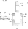
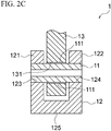
- FIG. 2A is a perspective view (before assembly) illustrating an embodiment of a fitted component according to the present invention
- FIG. 2B is a central cross-sectional view of the same (before assembly)
- FIG. 2C is a central cross-sectional view of the same (after assembly).
- the fitted component as an object of the heat treatment method or assembly method in the present embodiment comprises at least a first steel component 11, a second steel component 12, and a third component 13. It should be noted, however, that the third component is not an essential component in the fitted component according to the present invention.
- the first steel component 11 is a hollow steel component (or may also be a solid steel component).
- the first steel component 11 is formed with a coating 111, such as a diamond-like carbon film (DLC film), within an area of the outer surface to be in sliding contact with a second hole 131 of the third component 13.
- a coating 111 such as a diamond-like carbon film (DLC film)
- DLC film diamond-like carbon film
- the second steel component 12 comprises a base part 125 and a pair of wall parts 121 and 122 that are provided to stand from the base part 125 so as to have a certain space between the wall parts 121 and 122.
- the wall parts 121 and 122 are respectively formed with the first holes 123 and 124 in which the first steel component 11 is to be fitted.
- the outer diameter dimension of the first steel component 11 and the inner diameter dimension of the first holes are processed to predetermined fitting dimensions.
- One end part of the third component 13 is inserted between the wall parts 121 and 122. In this state, the first steel component 11 is inserted in the second hole 131 and fitted in the first holes 123 and 124, and the third component 13 is thereby pivotably supported with respect to the second steel component 12.
- One end part of the third component 13 is formed with the second hole in which the first steel component 11 is inserted.
- the first steel component 11, the second steel component, and the third component 13 are assembled to constitute a machine element such as a link.
- the second steel component 12 is subjected to a quenching treatment. That is, to enhance the wear resistance of the second steel component 12 by hardening its component surface, the quenching treatment is performed which includes heating the second steel component 12 to a temperature at which the metal structure of the component surface becomes an austenite structure and then rapidly cooling it thereby to generate a hard and dense ⁇ -martensite structure.
- the first steel component 11 is fitted in the first holes 123 and 124 of the second steel component 12.
- the surface of the second steel component 12 including the first holes 123 and 124 is hardened because the second steel component 12 has been subjected to the quenching treatment. If, in this state, the first steel component 11 is press-fitted into the first holes 123 and 124 of the second steel component 12, the coating 111 such as DLC formed on the surface of the first steel component 11 is highly likely to delaminate.
- a chemical conversion coating having lubricity is formed for the press fitting as in the cited conventional technique, delamination of the coating 111 can be suppressed, but the coating having lubricity has to be applied to the surface of the first steel component 11, so that not only the production cost increases but also the coating having lubricity is removed at the time of press fitting and mixed into the second steel component 12 and/or the third component 13, which may lead to contamination.
- the surface of the second steel component 12 subjected to the quenching treatment is hard and has high wear resistance, but the impact strength (toughness) is low.
- a tempering treatment may be carried out to keep the second steel component 12 at a relatively low temperature of about 150-220°C.
- the ⁇ -martensite structure can be changed to a ⁇ -martensite structure having a relatively low carbon concentration to improve the toughness.
- this reaction requires a long time because the transformation from the ⁇ -martensite structure to the ⁇ -martensite structure, which occurs in the tempering treatment, is a diffusion and aggregation phenomenon of carbon. Thus, a problem arises in that the treatment time is prolonged.
- a dedicated tempering treatment is not performed, and the first steel component 11 and the second steel component 12 are fitted together by shrink fitting rather than press fitting. Then, in consideration of the fact that the shrink fitting requires a temperature difference ⁇ T between the first steel component 11 and the second steel component 12, the second steel component 12 is heated to a first temperature T 1 that is equal to or higher than a tempering temperature T 0 of the second steel component 12 and higher than a temperature of the first steel component 11 by the temperature difference ⁇ T for achieving the shrink fitting.
- the tempering temperature of the second steel component 12 is equal to or higher than 150°C (but equal to or lower than an A 1 transformation temperature of 730°C)
- the temperature of the first steel component 11 is a room temperature of 20°C
- the temperature difference ⁇ T required for the second steel component 12 to be shrink-fitted with the first steel component 11 is 260°C
- the second steel component 12 is heated to 280°C.
- the temperature difference ⁇ T required for the second steel component 12 to be shrink-fitted with the first steel component 11 is a large difference such as 340°C, for example, the second steel component 12 is heated to 280°C and the first steel component 11 is cooled to -50°C.
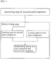
- the heating temperature (first temperature T 1 ) of the second steel component 12 in the shrink-fitting step as illustrated in FIG. 1 is the first temperature T 1 that is equal to or higher than the tempering temperature T 0 of the second steel component 12 and higher than the temperature of the first steel component 11 by the temperature difference ⁇ T for achieving the shrink fitting.
- the temperature difference ⁇ T for achieving the shrink fitting between the first steel component 11 and the second steel component 12 depends on the predetermined fitting dimensions of the outer diameter dimension of the first steel component 11 and the inner diameter dimension of the first holes.
- FIG. 4 is a graph illustrating a temperature condition for the first steel component 11 and the second steel component 12 to be heat-treated in the present embodiment.
- the first steel component 11 is shrink-fitted in the first holes 123 and 124 of the second steel component 12.
- a time t1 illustrated in FIG. 4 is provided to ensure the tempering time. It is preferred to perform the shrink fitting immediately after heating the second steel component 12 to the first temperature T 1 and cooling the first steel component 11 to the second temperature T 2 , but it may often be difficult to do so in an actual line. It is therefore preferred to maintain each of the temperatures T 1 and T 2 until the shrink fitting so that the temperature difference ⁇ T can be ensured at least during the shrink fitting.
- FIG. 3 is a side view illustrating an example in which the process flow illustrated in FIG. 1 is developed as an actual line.
- a heating furnace 21 for the second steel components 12, a heat-retaining furnace 22 and a conveying apparatus 24 for the second steel components 12, a cooling bath 23 and a shrink-fitting apparatus 26 for the first steel components 11, and a conveying apparatus 25 for the third components 13 are arranged in this order from the right side of the figure.
- the heat-retaining furnace 22 for the second steel components 12, which is a tunnel-like furnace covered with a heating insulating material, for example, maintains the second steel components 12 at the first temperature T 1 or a temperature slightly lower than the first temperature T 1 and ensures the tempering time for the second steel components 12 through ensuring the time t1 required for the second steel components 12 to be conveyed to the shrink-fitting step by the conveying apparatus 24.
- the cooling bath 23 for the first steel components 11 is filled with liquid nitrogen 27, for example, and the first steel components 11 are immersed in the liquid nitrogen 27 thereby to be cooled to the second temperature T 2 .
- the conveying apparatus 25 conveys the third components 13 to the shrink-fitting step.
- the shrink-fitting apparatus 26 (including a robot (not illustrated)) operates to insert each third component 13 between the pair of wall parts of each second steel component 12 while grasping the first steel component 11, second steel component 12, and third component 13 and insert the first steel component 11 in the second hole 131 when shrink-fitting the first steel component 11 in the first holes 123 and 124 of the second steel component 12.
- the fitted component 1 thus assembled is delivered to the next step by a conveying apparatus (not illustrated).
- FIG. 5 is a graph obtained by evaluating the surface condition of the heat-treated and assembled component in the present embodiment.
- “Example” represents the result of measurement in which the first steel component 11 was cut out from the fitted component 1 assembled in the heat treatment step as illustrated in FIG. 1 and the friction resistance of the coating 111 portion of the first steel component 11 was measured using a vibration frictional wear tester.
- “Comparative Example” represents the result of measurement in which the second steel component 12 was subjected to a tempering treatment of 180°C ⁇ 70 min instead of the tempering step illustrated in FIG. 1 and the first steel component 11 was press-fitted into the second steel component 12.
- the friction resistance of the coating 111 of the first steel component 11 in “Example” is apparently smaller than that in “Comparative Example.”
- FIG. 6 is a set of photomicrographs obtained by evaluating the surface condition of the heat-treated and assembled component in the present embodiment when observing the surfaces of "Example” and “Comparative Example” produced for the measurement illustrated in FIG. 5 .
- “Comparative Example” streaks and delamination (portion marked with the oval) were observed on the surface, but in “Example,” no streaks and delamination were observed on the surface.
- the first steel component 11 is shrink-fitted in the first holes 123 and 124 of the second steel component 12 in a state of maintaining the temperature difference ⁇ T for achieving the shrink fitting between the first steel component 11 and the second steel component 12 and gaps are therefore formed between the first steel component 11 and the first holes 123 and 124.
- the tempering treatment can be performed without providing a dedicated tempering step because, for the shrink fitting, the second steel component 12 is heated to a temperature equal to or higher than the tempering temperature T 0 . As a result, both the wear resistance and the impact strength of the second steel component 12 can be improved.
- the first steel component 11 is cooled to the second temperature T 2 to ensure the temperature difference ⁇ T for achieving the shrink fitting between the first steel component 11 and the second steel component 12. Therefore, even under the fitting condition in which the temperature difference ⁇ T is large, the heat treatment can be performed without heating the second steel component 12 to the A 1 transformation temperature of 730°C.
- the first steel component 11 is cooled to the second temperature T 2
- the first steel component 11 is carried to the shrink-fitting step while keeping the temperature of the first steel component 11
- the second steel component 12 is carried to the shrink-fitting step while keeping the temperature of the second steel component 12. This can ensure the temperature difference ⁇ T for achieving the shrink fitting and can also ensure the tempering time.
Landscapes
- Engineering & Computer Science (AREA)
- General Engineering & Computer Science (AREA)
- Mechanical Engineering (AREA)
- Automatic Assembly (AREA)
- Heat Treatment Of Articles (AREA)
Applications Claiming Priority (1)
| Application Number | Priority Date | Filing Date | Title |
|---|---|---|---|
| PCT/JP2016/077421 WO2018051484A1 (ja) | 2016-09-16 | 2016-09-16 | 嵌合部品の熱処理方法及び組立方法 |
Publications (3)
| Publication Number | Publication Date |
|---|---|
| EP3513902A1 true EP3513902A1 (de) | 2019-07-24 |
| EP3513902A4 EP3513902A4 (de) | 2019-10-02 |
| EP3513902B1 EP3513902B1 (de) | 2020-07-22 |
Family
ID=61618697
Family Applications (1)
| Application Number | Title | Priority Date | Filing Date |
|---|---|---|---|
| EP16916265.8A Active EP3513902B1 (de) | 2016-09-16 | 2016-09-16 | Montageverfahren für montierte komponente |
Country Status (5)
| Country | Link |
|---|---|
| US (2) | US20190255665A1 (de) |
| EP (1) | EP3513902B1 (de) |
| JP (1) | JP6721052B2 (de) |
| CN (1) | CN109689280B (de) |
| WO (1) | WO2018051484A1 (de) |
Cited By (1)
| Publication number | Priority date | Publication date | Assignee | Title |
|---|---|---|---|---|
| CN111673640A (zh) * | 2020-06-17 | 2020-09-18 | 中国原子能科学研究院 | 一种支撑装置 |
Families Citing this family (1)
| Publication number | Priority date | Publication date | Assignee | Title |
|---|---|---|---|---|
| JP6799878B1 (ja) * | 2020-06-16 | 2020-12-16 | 松本工業株式会社 | 接合部材の製造方法 |
Family Cites Families (17)
| Publication number | Priority date | Publication date | Assignee | Title |
|---|---|---|---|---|
| JPS59115128A (ja) * | 1982-12-23 | 1984-07-03 | Toshiba Corp | 焼ばめロ−タ |
| JPS618232A (ja) * | 1984-06-20 | 1986-01-14 | Daido Kogyo Co Ltd | 自転車、自動二輪車用スプロケツトの製造方法 |
| JPS63185536A (ja) * | 1987-01-28 | 1988-08-01 | Kuroki Kogyosho:Kk | 二重管の製造方法 |
| JPS6434614A (en) * | 1987-07-28 | 1989-02-06 | Musashi Seimitsu Kogyo Kk | Ring gear assembly method |
| DK269990A (da) * | 1990-11-12 | 1992-02-12 | Man B & W Diesel Gmbh | Krumtapaksel til en forbraendingsmotor |
| JP3791591B2 (ja) * | 2000-11-29 | 2006-06-28 | 株式会社デンソー | 燃料噴射弁とそのスプリング力調整用のアジャストパイプ及びその圧入方法 |
| JP2004090130A (ja) * | 2002-08-30 | 2004-03-25 | Mitsubishi Heavy Ind Ltd | TiAl基合金と鋼材の接合方法 |
| US8302833B2 (en) | 2004-04-02 | 2012-11-06 | Black & Decker Inc. | Power take off for cordless nailer |
| DE102007024091A1 (de) * | 2007-05-22 | 2008-11-27 | Mahle International Gmbh | Verfahren zum gleichzeitigen Vergüten und Fügen |
| AU2010269254A1 (en) * | 2009-07-10 | 2012-03-01 | Progressive Ip Limited | Improvements in and relating to improving the integrity of the union between components |
| US9115554B2 (en) | 2010-11-19 | 2015-08-25 | Baker Hughes Incorporated | Earth-boring tools including replaceable cutting structures and related methods |
| EP2677227B1 (de) * | 2012-06-19 | 2015-08-12 | Technip Norge AS | Rohrleitung mit Opferanoden und Verfahren zur Herstellung einer solchen Rohrleitung |
| DE102012020674A1 (de) * | 2012-10-22 | 2014-04-24 | Volkswagen Aktiengesellschaft | Verfahren zum Verbinden einer Wellenkomponente mit einer Nabenkomponente durch eine Welle-Nabe-Pressverbindung mit metallischer Zwischenschicht einschließlich Trainiervorgang, sowie hiermit hergestellte Baueinheit |
| CN104551528A (zh) * | 2013-10-21 | 2015-04-29 | 哈尔滨飞机工业集团有限责任公司 | 一种复合材料桨叶镶嵌内衬套的温差装配法 |
| CA2931644C (en) | 2013-11-26 | 2019-08-06 | S.P.M. Flow Control, Inc. | Valve seats for use in fracturing pumps |
| JP6330358B2 (ja) * | 2014-02-12 | 2018-05-30 | 株式会社ジェイテクト | 焼き嵌め方法及び焼き嵌め装置 |
| US10012318B2 (en) | 2015-03-24 | 2018-07-03 | Parker-Hannifin Corporation | Shuttle valve stabilization through pressure differential and shuttle valve with hollow poppet with weep hole |
-
2016
- 2016-09-16 WO PCT/JP2016/077421 patent/WO2018051484A1/ja not_active Ceased
- 2016-09-16 JP JP2018539471A patent/JP6721052B2/ja active Active
- 2016-09-16 CN CN201680089057.0A patent/CN109689280B/zh active Active
- 2016-09-16 US US16/333,470 patent/US20190255665A1/en not_active Abandoned
- 2016-09-16 EP EP16916265.8A patent/EP3513902B1/de active Active
-
2020
- 2020-03-06 US US16/811,066 patent/US11000924B2/en active Active
Cited By (1)
| Publication number | Priority date | Publication date | Assignee | Title |
|---|---|---|---|---|
| CN111673640A (zh) * | 2020-06-17 | 2020-09-18 | 中国原子能科学研究院 | 一种支撑装置 |
Also Published As
| Publication number | Publication date |
|---|---|
| CN109689280A (zh) | 2019-04-26 |
| US20200206850A1 (en) | 2020-07-02 |
| JP6721052B2 (ja) | 2020-07-08 |
| CN109689280B (zh) | 2021-03-02 |
| US20190255665A1 (en) | 2019-08-22 |
| EP3513902A4 (de) | 2019-10-02 |
| JPWO2018051484A1 (ja) | 2019-07-18 |
| WO2018051484A1 (ja) | 2018-03-22 |
| US11000924B2 (en) | 2021-05-11 |
| EP3513902B1 (de) | 2020-07-22 |
Similar Documents
| Publication | Publication Date | Title |
|---|---|---|
| US11000924B2 (en) | Heat treatment method and assembly method for fitted component | |
| JP2009221593A (ja) | ローラフォロア、動弁装置、高周波焼入設備、軸部材の熱処理方法、軸の製造方法および軸 | |
| US10737354B2 (en) | Bearing component | |
| JP2009197312A (ja) | 環状部材の変形矯正方法 | |
| CN105209214A (zh) | 通过扩散焊接接合两种材料的方法 | |
| JP2009204024A (ja) | 大型転がり軸受 | |
| WO2018012626A1 (ja) | 熱処理方法及び熱処理装置 | |
| CN108884872B (zh) | 滚子轴承用轴承圈及其制造方法和滚子轴承 | |
| CN105263664B (zh) | 获得机械部件的工艺 | |
| JP2010025311A (ja) | 転がり軸受及びその製造方法 | |
| US10393180B2 (en) | Bearing ring for roller bearing, manufacturing method of bearing ring for roller bearing, and needle roller bearing | |
| JP5433932B2 (ja) | 環状体の変形矯正方法 | |
| JP2005113213A (ja) | 熱処理システム | |
| JP2005133214A (ja) | 熱処理システム | |
| JP7378201B2 (ja) | 軸受部品の製造方法 | |
| JP2005133212A (ja) | 熱処理システム | |
| JP2005133211A (ja) | 熱処理システム | |
| JP4318999B2 (ja) | 熱処理システム | |
| JP2005133215A (ja) | 熱処理システム | |
| JP2005113210A (ja) | 熱処理システム | |
| JP2007321192A (ja) | 軸の焼入れ方法、軌道面を有する軸の製造方法 | |
| JP2019070176A (ja) | 転がり摺動部材及びその製造方法、並びに、当該転がり摺動部材を用いた転がり軸受 | |
| STEELS | INDUCTION HARDENING | |
| JP2005113217A (ja) | 熱処理システム | |
| JP2021011598A (ja) | 機械部品 |
Legal Events
| Date | Code | Title | Description |
|---|---|---|---|
| STAA | Information on the status of an ep patent application or granted ep patent |
Free format text: STATUS: THE INTERNATIONAL PUBLICATION HAS BEEN MADE |
|
| PUAI | Public reference made under article 153(3) epc to a published international application that has entered the european phase |
Free format text: ORIGINAL CODE: 0009012 |
|
| STAA | Information on the status of an ep patent application or granted ep patent |
Free format text: STATUS: REQUEST FOR EXAMINATION WAS MADE |
|
| 17P | Request for examination filed |
Effective date: 20190308 |
|
| AK | Designated contracting states |
Kind code of ref document: A1 Designated state(s): AL AT BE BG CH CY CZ DE DK EE ES FI FR GB GR HR HU IE IS IT LI LT LU LV MC MK MT NL NO PL PT RO RS SE SI SK SM TR |
|
| AX | Request for extension of the european patent |
Extension state: BA ME |
|
| A4 | Supplementary search report drawn up and despatched |
Effective date: 20190902 |
|
| RIC1 | Information provided on ipc code assigned before grant |
Ipc: F16B 4/00 20060101ALI20190827BHEP Ipc: B23P 11/02 20060101AFI20190827BHEP |
|
| DAV | Request for validation of the european patent (deleted) | ||
| DAX | Request for extension of the european patent (deleted) | ||
| GRAP | Despatch of communication of intention to grant a patent |
Free format text: ORIGINAL CODE: EPIDOSNIGR1 |
|
| STAA | Information on the status of an ep patent application or granted ep patent |
Free format text: STATUS: GRANT OF PATENT IS INTENDED |
|
| RIC1 | Information provided on ipc code assigned before grant |
Ipc: F16C 11/04 20060101ALI20200331BHEP Ipc: F16C 11/02 20060101ALI20200331BHEP Ipc: F16B 4/00 20060101ALI20200331BHEP Ipc: F16D 1/08 20060101ALN20200331BHEP Ipc: B23P 11/02 20060101AFI20200331BHEP |
|
| INTG | Intention to grant announced |
Effective date: 20200421 |
|
| GRAS | Grant fee paid |
Free format text: ORIGINAL CODE: EPIDOSNIGR3 |
|
| GRAA | (expected) grant |
Free format text: ORIGINAL CODE: 0009210 |
|
| STAA | Information on the status of an ep patent application or granted ep patent |
Free format text: STATUS: THE PATENT HAS BEEN GRANTED |
|
| AK | Designated contracting states |
Kind code of ref document: B1 Designated state(s): AL AT BE BG CH CY CZ DE DK EE ES FI FR GB GR HR HU IE IS IT LI LT LU LV MC MK MT NL NO PL PT RO RS SE SI SK SM TR |
|
| REG | Reference to a national code |
Ref country code: GB Ref legal event code: FG4D |
|
| REG | Reference to a national code |
Ref country code: CH Ref legal event code: EP |
|
| REG | Reference to a national code |
Ref country code: DE Ref legal event code: R096 Ref document number: 602016040637 Country of ref document: DE |
|
| REG | Reference to a national code |
Ref country code: AT Ref legal event code: REF Ref document number: 1292963 Country of ref document: AT Kind code of ref document: T Effective date: 20200815 |
|
| REG | Reference to a national code |
Ref country code: IE Ref legal event code: FG4D |
|
| REG | Reference to a national code |
Ref country code: LT Ref legal event code: MG4D |
|
| REG | Reference to a national code |
Ref country code: AT Ref legal event code: MK05 Ref document number: 1292963 Country of ref document: AT Kind code of ref document: T Effective date: 20200722 |
|
| PG25 | Lapsed in a contracting state [announced via postgrant information from national office to epo] |
Ref country code: FI Free format text: LAPSE BECAUSE OF FAILURE TO SUBMIT A TRANSLATION OF THE DESCRIPTION OR TO PAY THE FEE WITHIN THE PRESCRIBED TIME-LIMIT Effective date: 20200722 Ref country code: NO Free format text: LAPSE BECAUSE OF FAILURE TO SUBMIT A TRANSLATION OF THE DESCRIPTION OR TO PAY THE FEE WITHIN THE PRESCRIBED TIME-LIMIT Effective date: 20201022 Ref country code: SE Free format text: LAPSE BECAUSE OF FAILURE TO SUBMIT A TRANSLATION OF THE DESCRIPTION OR TO PAY THE FEE WITHIN THE PRESCRIBED TIME-LIMIT Effective date: 20200722 Ref country code: AT Free format text: LAPSE BECAUSE OF FAILURE TO SUBMIT A TRANSLATION OF THE DESCRIPTION OR TO PAY THE FEE WITHIN THE PRESCRIBED TIME-LIMIT Effective date: 20200722 Ref country code: BG Free format text: LAPSE BECAUSE OF FAILURE TO SUBMIT A TRANSLATION OF THE DESCRIPTION OR TO PAY THE FEE WITHIN THE PRESCRIBED TIME-LIMIT Effective date: 20201022 Ref country code: GR Free format text: LAPSE BECAUSE OF FAILURE TO SUBMIT A TRANSLATION OF THE DESCRIPTION OR TO PAY THE FEE WITHIN THE PRESCRIBED TIME-LIMIT Effective date: 20201023 Ref country code: ES Free format text: LAPSE BECAUSE OF FAILURE TO SUBMIT A TRANSLATION OF THE DESCRIPTION OR TO PAY THE FEE WITHIN THE PRESCRIBED TIME-LIMIT Effective date: 20200722 Ref country code: LT Free format text: LAPSE BECAUSE OF FAILURE TO SUBMIT A TRANSLATION OF THE DESCRIPTION OR TO PAY THE FEE WITHIN THE PRESCRIBED TIME-LIMIT Effective date: 20200722 Ref country code: PT Free format text: LAPSE BECAUSE OF FAILURE TO SUBMIT A TRANSLATION OF THE DESCRIPTION OR TO PAY THE FEE WITHIN THE PRESCRIBED TIME-LIMIT Effective date: 20201123 Ref country code: HR Free format text: LAPSE BECAUSE OF FAILURE TO SUBMIT A TRANSLATION OF THE DESCRIPTION OR TO PAY THE FEE WITHIN THE PRESCRIBED TIME-LIMIT Effective date: 20200722 |
|
| PG25 | Lapsed in a contracting state [announced via postgrant information from national office to epo] |
Ref country code: PL Free format text: LAPSE BECAUSE OF FAILURE TO SUBMIT A TRANSLATION OF THE DESCRIPTION OR TO PAY THE FEE WITHIN THE PRESCRIBED TIME-LIMIT Effective date: 20200722 Ref country code: LV Free format text: LAPSE BECAUSE OF FAILURE TO SUBMIT A TRANSLATION OF THE DESCRIPTION OR TO PAY THE FEE WITHIN THE PRESCRIBED TIME-LIMIT Effective date: 20200722 Ref country code: RS Free format text: LAPSE BECAUSE OF FAILURE TO SUBMIT A TRANSLATION OF THE DESCRIPTION OR TO PAY THE FEE WITHIN THE PRESCRIBED TIME-LIMIT Effective date: 20200722 Ref country code: IS Free format text: LAPSE BECAUSE OF FAILURE TO SUBMIT A TRANSLATION OF THE DESCRIPTION OR TO PAY THE FEE WITHIN THE PRESCRIBED TIME-LIMIT Effective date: 20201122 |
|
| PG25 | Lapsed in a contracting state [announced via postgrant information from national office to epo] |
Ref country code: NL Free format text: LAPSE BECAUSE OF FAILURE TO SUBMIT A TRANSLATION OF THE DESCRIPTION OR TO PAY THE FEE WITHIN THE PRESCRIBED TIME-LIMIT Effective date: 20200722 |
|
| REG | Reference to a national code |
Ref country code: DE Ref legal event code: R097 Ref document number: 602016040637 Country of ref document: DE |
|
| PG25 | Lapsed in a contracting state [announced via postgrant information from national office to epo] |
Ref country code: EE Free format text: LAPSE BECAUSE OF FAILURE TO SUBMIT A TRANSLATION OF THE DESCRIPTION OR TO PAY THE FEE WITHIN THE PRESCRIBED TIME-LIMIT Effective date: 20200722 Ref country code: IT Free format text: LAPSE BECAUSE OF FAILURE TO SUBMIT A TRANSLATION OF THE DESCRIPTION OR TO PAY THE FEE WITHIN THE PRESCRIBED TIME-LIMIT Effective date: 20200722 Ref country code: SM Free format text: LAPSE BECAUSE OF FAILURE TO SUBMIT A TRANSLATION OF THE DESCRIPTION OR TO PAY THE FEE WITHIN THE PRESCRIBED TIME-LIMIT Effective date: 20200722 Ref country code: RO Free format text: LAPSE BECAUSE OF FAILURE TO SUBMIT A TRANSLATION OF THE DESCRIPTION OR TO PAY THE FEE WITHIN THE PRESCRIBED TIME-LIMIT Effective date: 20200722 Ref country code: DK Free format text: LAPSE BECAUSE OF FAILURE TO SUBMIT A TRANSLATION OF THE DESCRIPTION OR TO PAY THE FEE WITHIN THE PRESCRIBED TIME-LIMIT Effective date: 20200722 Ref country code: CZ Free format text: LAPSE BECAUSE OF FAILURE TO SUBMIT A TRANSLATION OF THE DESCRIPTION OR TO PAY THE FEE WITHIN THE PRESCRIBED TIME-LIMIT Effective date: 20200722 |
|
| REG | Reference to a national code |
Ref country code: CH Ref legal event code: PL |
|
| PLBE | No opposition filed within time limit |
Free format text: ORIGINAL CODE: 0009261 |
|
| STAA | Information on the status of an ep patent application or granted ep patent |
Free format text: STATUS: NO OPPOSITION FILED WITHIN TIME LIMIT |
|
| PG25 | Lapsed in a contracting state [announced via postgrant information from national office to epo] |
Ref country code: AL Free format text: LAPSE BECAUSE OF FAILURE TO SUBMIT A TRANSLATION OF THE DESCRIPTION OR TO PAY THE FEE WITHIN THE PRESCRIBED TIME-LIMIT Effective date: 20200722 |
|
| REG | Reference to a national code |
Ref country code: BE Ref legal event code: MM Effective date: 20200930 |
|
| 26N | No opposition filed |
Effective date: 20210423 |
|
| PG25 | Lapsed in a contracting state [announced via postgrant information from national office to epo] |
Ref country code: SK Free format text: LAPSE BECAUSE OF FAILURE TO SUBMIT A TRANSLATION OF THE DESCRIPTION OR TO PAY THE FEE WITHIN THE PRESCRIBED TIME-LIMIT Effective date: 20200722 Ref country code: LU Free format text: LAPSE BECAUSE OF NON-PAYMENT OF DUE FEES Effective date: 20200916 |
|
| PG25 | Lapsed in a contracting state [announced via postgrant information from national office to epo] |
Ref country code: BE Free format text: LAPSE BECAUSE OF NON-PAYMENT OF DUE FEES Effective date: 20200930 Ref country code: CH Free format text: LAPSE BECAUSE OF NON-PAYMENT OF DUE FEES Effective date: 20200930 Ref country code: SI Free format text: LAPSE BECAUSE OF FAILURE TO SUBMIT A TRANSLATION OF THE DESCRIPTION OR TO PAY THE FEE WITHIN THE PRESCRIBED TIME-LIMIT Effective date: 20200722 Ref country code: LI Free format text: LAPSE BECAUSE OF NON-PAYMENT OF DUE FEES Effective date: 20200930 Ref country code: IE Free format text: LAPSE BECAUSE OF NON-PAYMENT OF DUE FEES Effective date: 20200916 |
|
| REG | Reference to a national code |
Ref country code: NL Ref legal event code: MP Effective date: 20200722 |
|
| PG25 | Lapsed in a contracting state [announced via postgrant information from national office to epo] |
Ref country code: TR Free format text: LAPSE BECAUSE OF FAILURE TO SUBMIT A TRANSLATION OF THE DESCRIPTION OR TO PAY THE FEE WITHIN THE PRESCRIBED TIME-LIMIT Effective date: 20200722 Ref country code: MT Free format text: LAPSE BECAUSE OF FAILURE TO SUBMIT A TRANSLATION OF THE DESCRIPTION OR TO PAY THE FEE WITHIN THE PRESCRIBED TIME-LIMIT Effective date: 20200722 Ref country code: CY Free format text: LAPSE BECAUSE OF FAILURE TO SUBMIT A TRANSLATION OF THE DESCRIPTION OR TO PAY THE FEE WITHIN THE PRESCRIBED TIME-LIMIT Effective date: 20200722 |
|
| PG25 | Lapsed in a contracting state [announced via postgrant information from national office to epo] |
Ref country code: MK Free format text: LAPSE BECAUSE OF FAILURE TO SUBMIT A TRANSLATION OF THE DESCRIPTION OR TO PAY THE FEE WITHIN THE PRESCRIBED TIME-LIMIT Effective date: 20200722 Ref country code: MC Free format text: LAPSE BECAUSE OF FAILURE TO SUBMIT A TRANSLATION OF THE DESCRIPTION OR TO PAY THE FEE WITHIN THE PRESCRIBED TIME-LIMIT Effective date: 20200722 |
|
| REG | Reference to a national code |
Ref country code: DE Ref legal event code: R084 Ref document number: 602016040637 Country of ref document: DE |
|
| REG | Reference to a national code |
Ref country code: GB Ref legal event code: 746 Effective date: 20230926 |
|
| PGFP | Annual fee paid to national office [announced via postgrant information from national office to epo] |
Ref country code: DE Payment date: 20250820 Year of fee payment: 10 |
|
| PGFP | Annual fee paid to national office [announced via postgrant information from national office to epo] |
Ref country code: GB Payment date: 20250820 Year of fee payment: 10 |
|
| PGFP | Annual fee paid to national office [announced via postgrant information from national office to epo] |
Ref country code: FR Payment date: 20250820 Year of fee payment: 10 |