EP3513668B1 - Zerstäuber und elektronische zigarette damit - Google Patents
Zerstäuber und elektronische zigarette damit Download PDFInfo
- Publication number
- EP3513668B1 EP3513668B1 EP17863105.7A EP17863105A EP3513668B1 EP 3513668 B1 EP3513668 B1 EP 3513668B1 EP 17863105 A EP17863105 A EP 17863105A EP 3513668 B1 EP3513668 B1 EP 3513668B1
- Authority
- EP
- European Patent Office
- Prior art keywords
- air
- tobacco tar
- cavity
- atomizing
- cotton
- Prior art date
- Legal status (The legal status is an assumption and is not a legal conclusion. Google has not performed a legal analysis and makes no representation as to the accuracy of the status listed.)
- Active
Links
Images




Classifications
-
- A—HUMAN NECESSITIES
- A24—TOBACCO; CIGARS; CIGARETTES; SIMULATED SMOKING DEVICES; SMOKERS' REQUISITES
- A24F—SMOKERS' REQUISITES; MATCH BOXES; SIMULATED SMOKING DEVICES
- A24F40/00—Electrically operated smoking devices; Component parts thereof; Manufacture thereof; Maintenance or testing thereof; Charging means specially adapted therefor
- A24F40/40—Constructional details, e.g. connection of cartridges and battery parts
- A24F40/42—Cartridges or containers for inhalable precursors
-
- A—HUMAN NECESSITIES
- A24—TOBACCO; CIGARS; CIGARETTES; SIMULATED SMOKING DEVICES; SMOKERS' REQUISITES
- A24F—SMOKERS' REQUISITES; MATCH BOXES; SIMULATED SMOKING DEVICES
- A24F40/00—Electrically operated smoking devices; Component parts thereof; Manufacture thereof; Maintenance or testing thereof; Charging means specially adapted therefor
- A24F40/40—Constructional details, e.g. connection of cartridges and battery parts
- A24F40/44—Wicks
-
- A—HUMAN NECESSITIES
- A24—TOBACCO; CIGARS; CIGARETTES; SIMULATED SMOKING DEVICES; SMOKERS' REQUISITES
- A24B—MANUFACTURE OR PREPARATION OF TOBACCO FOR SMOKING OR CHEWING; TOBACCO; SNUFF
- A24B15/00—Chemical features or treatment of tobacco; Tobacco substitutes, e.g. in liquid form
- A24B15/10—Chemical features of tobacco products or tobacco substitutes
- A24B15/16—Chemical features of tobacco products or tobacco substitutes of tobacco substitutes
- A24B15/167—Chemical features of tobacco products or tobacco substitutes of tobacco substitutes in liquid or vaporisable form, e.g. liquid compositions for electronic cigarettes
-
- A—HUMAN NECESSITIES
- A24—TOBACCO; CIGARS; CIGARETTES; SIMULATED SMOKING DEVICES; SMOKERS' REQUISITES
- A24F—SMOKERS' REQUISITES; MATCH BOXES; SIMULATED SMOKING DEVICES
- A24F40/00—Electrically operated smoking devices; Component parts thereof; Manufacture thereof; Maintenance or testing thereof; Charging means specially adapted therefor
-
- A—HUMAN NECESSITIES
- A24—TOBACCO; CIGARS; CIGARETTES; SIMULATED SMOKING DEVICES; SMOKERS' REQUISITES
- A24F—SMOKERS' REQUISITES; MATCH BOXES; SIMULATED SMOKING DEVICES
- A24F40/00—Electrically operated smoking devices; Component parts thereof; Manufacture thereof; Maintenance or testing thereof; Charging means specially adapted therefor
- A24F40/40—Constructional details, e.g. connection of cartridges and battery parts
-
- A—HUMAN NECESSITIES
- A24—TOBACCO; CIGARS; CIGARETTES; SIMULATED SMOKING DEVICES; SMOKERS' REQUISITES
- A24F—SMOKERS' REQUISITES; MATCH BOXES; SIMULATED SMOKING DEVICES
- A24F40/00—Electrically operated smoking devices; Component parts thereof; Manufacture thereof; Maintenance or testing thereof; Charging means specially adapted therefor
- A24F40/40—Constructional details, e.g. connection of cartridges and battery parts
- A24F40/48—Fluid transfer means, e.g. pumps
- A24F40/485—Valves; Apertures
-
- A—HUMAN NECESSITIES
- A24—TOBACCO; CIGARS; CIGARETTES; SIMULATED SMOKING DEVICES; SMOKERS' REQUISITES
- A24F—SMOKERS' REQUISITES; MATCH BOXES; SIMULATED SMOKING DEVICES
- A24F40/00—Electrically operated smoking devices; Component parts thereof; Manufacture thereof; Maintenance or testing thereof; Charging means specially adapted therefor
- A24F40/10—Devices using liquid inhalable precursors
-
- A—HUMAN NECESSITIES
- A61—MEDICAL OR VETERINARY SCIENCE; HYGIENE
- A61M—DEVICES FOR INTRODUCING MEDIA INTO, OR ONTO, THE BODY; DEVICES FOR TRANSDUCING BODY MEDIA OR FOR TAKING MEDIA FROM THE BODY; DEVICES FOR PRODUCING OR ENDING SLEEP OR STUPOR
- A61M11/00—Sprayers or atomisers specially adapted for therapeutic purposes
- A61M11/04—Sprayers or atomisers specially adapted for therapeutic purposes operated by the vapour pressure of the liquid to be sprayed or atomised
- A61M11/041—Sprayers or atomisers specially adapted for therapeutic purposes operated by the vapour pressure of the liquid to be sprayed or atomised using heaters
- A61M11/042—Sprayers or atomisers specially adapted for therapeutic purposes operated by the vapour pressure of the liquid to be sprayed or atomised using heaters electrical
-
- B—PERFORMING OPERATIONS; TRANSPORTING
- B05—SPRAYING OR ATOMISING IN GENERAL; APPLYING FLUENT MATERIALS TO SURFACES, IN GENERAL
- B05B—SPRAYING APPARATUS; ATOMISING APPARATUS; NOZZLES
- B05B7/00—Spraying apparatus for discharge of liquids or other fluent materials from two or more sources, e.g. of liquid and air, of powder and gas
- B05B7/16—Spraying apparatus for discharge of liquids or other fluent materials from two or more sources, e.g. of liquid and air, of powder and gas incorporating means for heating or cooling the material to be sprayed
- B05B7/1686—Spraying apparatus for discharge of liquids or other fluent materials from two or more sources, e.g. of liquid and air, of powder and gas incorporating means for heating or cooling the material to be sprayed involving vaporisation of the material to be sprayed or of an atomising-fluid-generating product
Definitions
- the present invention belongs to an atomizer and an electronic cigarette thereof.
- the existing ultrasonic high-frequency atomizing electronic cigarette generally transfers tobacco tar in a tobacco tar cavity to an atomizing sheet through tobacco tar storage cotton, and then atomizes the tobacco tar by high-frequency oscillation through an air inflow passage and an air outflow passage communicated with the atomizing surface of the atomizing sheet.
- the existing product has the following defects in practical application:
- the present invention is intended to provide an atomizer having high atomizing efficiency and producing a large amount of smoke, and an electronic cigarette thereof.
- an atomizer comprising an atomizer body, a suction nozzle assembly mounted at the top of the atomizer body, an air inlet provided in the atomizer body, an atomizing sheet and a tobacco tar cavity provided in the atomizer body, and a tobacco tar guide body which guides tobacco tar in the tobacco tar cavity to an atomizing surface of the atomizing sheet, a first air inflow passage which communicates with the air inlet and an air outflow pipe which communicates with the suction nozzle assembly are arranged in the atomizer body, the tobacco tar guide body comprises atomizing cotton which abuts against the atomizing surface of the atomizing sheet, the air outflow pipe is provided with an air guide structure, the lower end of the air guide structure abuts against the atomizing cotton, the air guide structure comprises an air guide passage closely attached to the atomizing cotton, and the air guide passage communicates with the inner cavity of the first air inflow passage as well as the inner cavity of the air
- the air guide passage is designed such that the air entering from the first air inflow passage can be guided to flow, therefore all the air can pass over, at a low level, the surface where the atomizing cotton is in contact with the atomizing sheet, the atomization is more sufficient, the atomizing efficiency is higher, more smoke is produced, the concentration of the obtained smoke is higher, and the mouthfeel of the smoke is improved.
- the atomizer body further comprises a shell and a connection electrode mounted at the bottom of the shell, the suction nozzle assembly is mounted at the top of the shell, and the atomizing sheet is electrically connected to the connection electrode; the atomizing cotton is of a hollow cylindrical structure, and the lower part of the air outflow pipe is inserted into the hollow cavity of the atomizing cotton.
- the air inlet is provided in the lower part of the shell in an area corresponding to the mounting position of the atomizing cotton, and the lower part of the atomizing cotton is provided with a first air pass hole which communicates with the first air inflow passage;
- the air guide structure further comprises a base body arranged at the lower part of the air outflow pipe and having a hollow cavity, the base body seals the hollow cavity of the atomizing cotton, the lower end of the base body tightly presses the atomizing cotton with the atomizing sheet from the bottom of the inner cavity of the atomizing cotton, the air guide passage is provided at the lower part of the base body and communicates with the first air pass hole as well as the hollow cavity of the base body, and the hollow cavity of the base body communicates with the air outflow pipe.
- the bottom of the tobacco tar cavity is sealed by a first seal seat, a groove is formed in the middle of the first seal seat, and a first tobacco tar isolation seat is mounted in the groove;
- the air guide passage may have various structures:
- the first air guide groove and the second air guide groove are adjacent to the contact portion of the atomizing cotton and the atomizing sheet to guide the air.
- the hollow cavity of the base body directly reaches the bottom of the base body, a cover which blocks the hollow cavity of the base body is arranged at the bottom of the base body, the cover is provided with a second air pass hole in a position corresponding to the first air pass hole, and the second air pass hole is the air guide passage; the bottom of the cover abuts against the atomizing cotton, and a third air pass hole is formed at the abutting position.
- the cover located at the bottom of the hollow cavity of the base body has certain elasticity, thus it has certain deformation space when abutting against the atomizing cotton to improve the contact effect between the atomizing cotton and the atomizing sheet, and at the same time, the second air pass hole has the effect to guide the air.
- the cover is spherical or inversely conical.
- the air inlet is provided at the upper part of the shell, an accommodating cavity is formed in the middle of the tobacco tar cavity, the air outflow pipe is arranged in the accommodating cavity, a gap A is reserved between the outer wall of the air outflow pipe and the inner wall of the accommodating cavity, and the gap A communicates with the air inlet to form the first air inflow passage;
- the air passage is provided, therefore, after air enters the first air inflow passage, the air is guided to flow through the second gap and the third gap, thereby ensuring that the air can flow along the inner wall of the hollow cavity of the atomizing cotton, thus the smoke generated at the corner of the atomizing cotton can be carried away to avoid the accumulation of smoke and increase the concentration of the smoke.
- the air pass groove air can be guided to flow, and all the air can pass over, at a low level, the surface where the atomizing cotton is in contact with the atomizing sheet, so that the atomization is more sufficient, the atomizing efficiency is higher, and more smoke is produced.
- the bottom of the tobacco tar cavity is sealed by a second seal seat, a groove is formed in the middle of the second seal seat, and a second tobacco tar isolation seat is mounted in the groove;
- the lower part of the second vertical portion is sleeved with a spring, the spring is wrapped by the atomizing cotton, the lower end of the spring abuts against the inner surface of the bottom of the atomizing cotton, the lower part of the air outflow pipe penetrates through the second tobacco tar isolation seat and is inserted into a central hole of the spring, and the flexible tube communicates with the first air outlet.
- the flexible tube is a glass fiber tube, and comprises a first glass fiber tube sleeved at the lower part of the air outflow pipe and a second glass fiber tube sleeved at the upper part of the outer wall of the first glass fiber tube; the length of the second glass fiber tube is shorter than that of the first glass fiber tube, and the air pass groove is formed at the lower part edge of the first glass fiber tube.
- the second glass fiber tube mainly improves the strength of the first glass fiber tube to prevent bending during assembly.
- a filter screen is arranged at the lower part of the inner cavity of the air outflow pipe.
- the filter screen is used for blocking tobacco tar from splashing or large particle smoke from being sucked into the user's mouth when the atomizing sheet is operated.
- the air inlet is provided at the upper part of the shell, a tobacco tar isolation cavity is formed in the middle of the tobacco tar cavity, an accommodating cavity is formed in the tobacco tar isolation cavity, the air outflow pipe is arranged in the accommodating cavity, a gap B is reserved between the outer wall of the air outflow pipe and the inner wall of the accommodating cavity, and the gap B communicates with the air inlet to form the first air inflow passage;
- the air guide structure comprises a liner tube which is sleeved in the inner cavity of the air outflow pipe and has the performance of thermal insulation and tobacco tar absorption, a gap C is reserved between the lower end of the air outflow pipe and the bottom of the hollow cavity of the atomizing cotton, the lower end of the liner tube stretches out of the lower end of the air outflow pipe and abuts against the bottom of the hollow cavity of the atomizing cotton, the lower part edge of the liner tube is provided with an air pass hole F which communicates with the first air inflow passage, and the air pass hole F
- the air pass hole F is designed such that the air can be guided to flow, thus all the air can pass over, at a low level, the surface where the atomizing cotton is in contact with the atomizing sheet, the atomization is more sufficient, the atomizing efficiency is higher, and more smoke is produced.
- the liner tube itself has the thermal insulation function, and the lower end of the air pipe is not in contact with the atomizing cotton, so that the heat produced by the atomizing sheet can be prevented from being transferred to the shell through the air pipe.
- the liner tube has the performance of tobacco tar absorption.
- the condensed smoke can adsorb the condensed tobacco tar, and is guided again to the atomizing cotton from top to bottom for secondary atomizing to prevent the condensed tobacco tar from being sucked into the mouth to affect the mouthfeel.
- the height of the air pass hole F is 0.2 to 0.7 mm.
- the reserved air pass hole is small, thus air can be guided to flow, and all the air can pass over, at a low level, the surface where the atomizing cotton is in contact with the atomizing sheet, so that the atomization is more sufficient.
- the accommodating cavity is composed of an outer sleeve and an inner sleeve sleeved in the inner cavity of the outer sleeve
- the outer sleeve comprises a hollow third seal seat arranged at the bottom of the tobacco tar cavity to seal the tobacco tar cavity and a vertical pipe fixed on the third seal seat
- the inner sleeve is sleeved in the inner cavity of the vertical pipe
- the inner cavity of the inner sleeve is the accommodating cavity
- tobacco tar storage cotton is sleeved on the outer wall of the vertical pipe at a position corresponding to the third tobacco tar pass holes, and the tobacco tar storage cotton is located in the tobacco tar cavity and covers the third tobacco tar pass holes.
- the tobacco tar storage cotton can control the tobacco tar transfer rate and prevent the atomizing cotton from absorbing too much tobacco tar to produce tobacco tar accumulation.
- the lower part of the inner cavity of the inner sleeve is sleeved with a spring, the lower end of the spring abuts against the inner surface of the bottom of the atomizing cotton, and the air outflow pipe with the liner tube is inserted into the hollow cavity of the inner sleeve as well as the central hole of the spring.
- the air outflow pipe is flush with the upper end of the liner tube, and a filter screen is arranged at the upper part of the liner tube.
- the filter screen is used for blocking tobacco tar from splashing or large particle smoke from being sucked into the user's mouth when the atomizing sheet is operated.
- the liner tube is a glass fiber tube
- the air pass hole F is zigzag groove or wave groove formed around the lower part edge of the liner tube.
- the height of the gap C between the air outflow pipe and the bottom of the hollow cavity of the atomizing cotton is more than 2 mm.
- the lower end of the air outflow pipe is not in contact with the atomizing cotton, which can prevent the heat produced by the atomizing sheet from being transferred to the shell through the air outflow pipe.
- the upper end of the liner tube extends out of the upper end of the air outflow pipe and extends into the inner cavity of the suction nozzle assembly, and a gap D is reserved between the outer wall of the liner tube and the inner cavity wall of the suction nozzle assembly; the suction nozzle assembly is detachably connected to the top of the shell.
- the liner tube is directly extended up to a suction nozzle, and the suction nozzle is made of other non-metallic material such as plastic or wood, so that the entire air outflow passage can greatly reduce the occurrence of condensation.
- the gap D is provided to facilitate the disassembly and assembly of the suction nozzle.
- a thermal insulation sheet is arranged between the lower surface of the atomizing sheet and the connection electrode.
- the thermal insulation sheet can prevent the heat of the atomizing sheet from being transferred from the lower part to the connection electrode and the shell.
- the atomizing sheet is a solid piezoelectric ceramic sheet.
- the present invention also provides an electronic cigarette, comprising an external power source, and the atomizer according to the above solution, wherein the external power source is connected to the connection electrode of the atomizer.
- the incoming air can be correctly guided to flow, so that all the air can pass over, at a low level, the surface where the atomizing cotton is in contact with the atomizing sheet, the atomization is more sufficient, the atomizing efficiency is higher, and more smoke is produced.
- cold air is prevented from flowing away directly from the air pipe to be mixed with the smoke to reduce the temperature of the smoke, thereby avoiding the phenomenon that the low temperature of the smoke affects the mouthfeel.
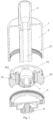
- an atomizer includes an atomizer body 50, a suction nozzle assembly 3 mounted at the top of the atomizer body 50, an air inlet 2 provided in the atomizer body 50, an atomizing sheet 5 and a tobacco tar cavity 4 provided in the atomizer body 50, and a tobacco tar guide body which guides tobacco tar in the tobacco tar cavity 4 to an atomizing surface of the atomizing sheet 5.
- a first air inflow passage 9 which communicates with the air inlet 2 and an air outflow pipe 12 which communicates with the suction nozzle assembly 3 are arranged in the atomizer body 50.
- the tobacco tar guide body includes atomizing cotton 7 which abuts against the atomizing surface of the atomizing sheet 5.
- the air outflow pipe 12 is provided with an air guide structure, and the lower end of the air guide structure abuts against the atomizing cotton 7.
- the air guide structure includes an air guide passage closely attached to the atomizing cotton 7, and the air guide passage communicates with the inner cavity of the first air inflow passage 9 as well as the inner cavity of the air outflow pipe 12.
- the atomizer body 50 further includes a shell 1 and a connection electrode 6 mounted at the bottom of the shell 1, the suction nozzle assembly 3 is mounted at the top of the shell 1, and the atomizing sheet 5 is electrically connected to the connection electrode 6.
- the atomizing cotton 7 is of a hollow cylindrical structure, and the lower part of the air outflow pipe 12 is inserted into the hollow cavity of the atomizing cotton 7.
- the air inlet is provided in the lower part of the shell 1 in an area corresponding to the mounting position of the atomizing cotton 7, and the lower part of the atomizing cotton 7 is provided with a first air pass hole 11 which communicate with the first air inflow passage 9.
- the air guide structure further includes a base body 81 arranged at the lower part of the air outflow pipe 12 and having a hollow cavity.
- the base body 81 blocks the hollow cavity of the atomizing cotton 7, and the lower end of the base body 81 tightly presses the atomizing cotton 7 with the atomizing sheet 5 from the bottom of the inner cavity of the atomizing cotton 7.
- the air guide passage is provided at the lower part of the base body 81 and communicates with the first air pass hole 11 as well as the hollow cavity of the base body 81, and the hollow cavity of the base body 81 communicates with the air outflow pipe 12.
- the bottom of the tobacco tar cavity 4 is sealed by a first seal seat 43, a groove is formed in the middle of the first seal seat 43, and a first tobacco tar isolation seat 44 is mounted in the groove.
- the first tobacco tar isolation seat 44 is T-shaped, and includes a first vertical portion 441 and a first flange edge 442 at the top of the first vertical portion 441.
- the first vertical portion 441 is inserted into the groove, a first gap is reserved between the first vertical portion 441 and the inner wall of the groove, the first gap is filled with tobacco tar storage cotton 10, and the first flange edge 442 is provided with a first tobacco tar pass hole 443, which communicates with the tobacco tar cavity 4, in a position corresponding to the tobacco tar storage cotton 10.
- the atomizing cotton 7 is wrapped on the outer wall of the first vertical portion 441, and the outer side of the atomizing cotton 7 abuts against the tobacco tar storage cotton 10.
- the base body 81 is fixedly connected to the first vertical portion 441.
- a first seal cover 82 that is open at the bottom is arranged at the lower part of the base body 81.
- a second seal cover 83 that is open at the bottom is arranged in the inner cavity of the first seal cover 82.
- a gap is reserved between the first seal cover 82 and the second seal cover 83, and the inner cavity of the second seal cover 83 communicates with the hollow cavity of the base body 81.
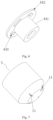
- the first seal cover 82 is provided with a first air guide grooves 84 in a position corresponding to the first air pass hole 11, and the second seal cover 83 is provided with second air guide grooves 85 in a position corresponding to the first air guide grooves 84.
- the air guide passage is formed among the first air guide groove 84, the second air guide groove 85, and the gap between the first seal cover 82 and the second seal cover 83.
- the first seal cover 82 and the second seal cover 83 abut against the atomizing cotton 7.
- the present embodiment further provides an electronic cigarette, including an external power source, and further including an atomizer according to the above solution, wherein the external power source is connected to the connection electrode 6 of the atomizer.
- Embodiment 1 As shown in Figures 4-7 , the contents of Embodiment 1 is repeated, except that the structure of the air guide passage is different.
- the hollow cavity of the base body 81 directly reaches the bottom of the base body 81, a spherical or inversely conical cover 86 which blocks the hollow cavity of the base body 81 is arranged at the bottom of the base body 81, the cover 86 is provided with a second air pass hole 13 in a position corresponding to the first air pass hole 11, and the second air pass hole 13 is the air guide passage.
- the bottom of the cover 86 abuts against the atomizing cotton 7, and a third air pass hole 14 is formed at the abutting position.
- an atomizer includes an atomizer body 50, a suction nozzle assembly 3 mounted at the top of the atomizer body 50, an air inlet 2 provided in the atomizer body 50, an atomizing sheet 5 and a tobacco tar cavity 4 provided in the atomizer body 50, and a tobacco tar guide body which guides tobacco tar in the tobacco tar cavity 4 to an atomizing surface of the atomizing sheet 5.
- a first air inflow passage 9 which communicates with the air inlet 2 and an air outflow pipe 12 which communicates with the suction nozzle assembly 3 are arranged in the atomizer body 50.
- the tobacco tar guide body includes atomizing cotton 7 which abuts against the atomizing surface of the atomizing sheet 5.
- the air outflow pipe 12 is provided with an air guide structure, and the lower end of the air guide structure abuts against the atomizing cotton 7.
- the air guide structure includes an air guide passage closely attached to the atomizing cotton 7, and the air guide passage communicates with the inner cavity of the first air inflow passage 9 as well as the inner cavity of the air outflow pipe 12.
- the atomizer body 50 further includes a shell 1 and a connection electrode 6 mounted at the bottom of the shell 1, the suction nozzle assembly 3 is mounted at the top of the shell 1, and the atomizing sheet 5 is electrically connected to the connection electrode 6.
- the atomizing sheet 5 is preferably a solid piezoelectric ceramic sheet.
- the atomizing cotton 7 is of a hollow cylindrical structure, and the lower part of the air outflow pipe 12 is inserted into the hollow cavity of the atomizing cotton 7.
- a first air outlet 1014 is formed at the bottom of the atomizing cotton 7.
- the air inlet 2 is provided at the upper part of the shell 1, and an accommodating cavity is formed in the middle of the tobacco tar cavity 4.
- the air outflow pipe 12 is arranged in the accommodating cavity, a gap A is reserved between the outer wall of the air outflow pipe 12 and the inner wall of the accommodating cavity, and the gap A communicates with the air inlet 2 to form the first air inflow passage 9.
- a flange 121 is arranged at the lower part of the air outflow pipe 12 near the orifice of the air outflow pipe 12.
- the air guide structure comprises a flexible tube 100 sleeved at the orifice of the air outflow pipe 12 below the flange 121, and the lower part of the flexible tube 100 is provided with an air pass groove 101.
- the bottom of the flexible tube 100 abuts against the bottom of the hollow cavity of the atomizing cotton 7.
- the flexible tube 100 is a glass fiber tube, and comprises a first glass fiber tube 102 sleeved at the lower part of the air outflow pipe 12 and a second glass fiber tube 103 sleeved at the upper part of the outer wall of the first glass fiber tube 102.
- the length of the second glass fiber tube 103 is shorter than that of the first glass fiber tube 102, and the air pass groove 101 is formed at the lower part edge of the first glass fiber tube 102.
- the upper surface of the flange 121 is directly opposite to the outlet of the first air inflow passage 9, and a second gap is reserved between the flange 121 and the outlet of the first air inflow passage 9.
- the side of the flange 121 is close to the inner wall of the hollow cavity of the atomizing cotton 7, and a third gap is reserved between the flange 121 and the inner wall of the hollow cavity of the atomizing cotton 7.
- the bottom of the tobacco tar cavity 4 is sealed by a second seal seat 1043, a groove is formed in the middle of the second seal seat 1043, and a second tobacco tar isolation seat 1044 is mounted in the groove.
- the second tobacco tar isolation seat 1044 is T-shaped and includes a second vertical portion 10441 and a second flange edge 10442 at the top of the second vertical portion 10441, the second vertical portion 10441 is inserted into the groove, a fourth gap is reserved between the second vertical portion 10441 and the inner wall of the groove, the fourth gap is filled with tobacco tar storage cotton 10, and the second flange edge 10442 is provided with a second tobacco tar pass hole 10443, which communicates with the tobacco tar cavity 4, in a position corresponding to the tobacco tar storage cotton 10.
- the side of the atomizing cotton 7 is wrapped on the outer wall of the second vertical portion 10441, and the side of the atomizing cotton 7 abuts against the tobacco tar storage cotton 10.
- the lower part of the second vertical portion 10441 is sleeved with a spring 8.
- the spring 8 is wrapped by the atomizing cotton 7, and and the lower end of the spring 8 abuts against the inner surface of the bottom of the atomizing cotton 7.
- the lower part of the air outflow pipe 12 penetrates through the second tobacco tar isolation seat 1044 and is inserted into the central hole of the spring 8, and the flexible tube 100 communicates with the first air outlet 1014.
- the present embodiment further provides an electronic cigarette, including an external power source, and further including an atomizer according to the above solution, wherein the external power source is connected to the connection electrode 6 of the atomizer.
- the air When the electronic cigarette is in operation, after the air enters the first air inflow passage 9, the air is guided to flow through the second gap and the third gap, flows along the inner wall of the hollow cavity of the atomizing cotton 7, and then carries away the smoke generated at corners of the atomizing cotton 7 to avoid accumulation of the smoke. Then, the air flows through the air pass groove 101 and is guided to flow, so that all the air can pass over, at a low level, the surface where the atomizing cotton 7 is in contact with the atomizing sheet 5, the atomization is more sufficient, the atomizing efficiency is higher, and more smoke is produced.
- Embodiment 3 As shown in Fig. 14 , the contents of Embodiment 3 is repeated, except that a filter screen 15 is arranged at the lower part of the inner cavity of the air outflow pipe 12, and the filter screen 15 is used for blocking tobacco tar from splashing or large particle smoke from being sucked into the user's mouth when the atomizing sheet 5 is in operation.
- an atomizer including an atomizer body 50, a suction nozzle assembly 3 mounted at the top of the atomizer body 50, an air inlet 2 provided in the atomizer body 50, an atomizing sheet 5 and a tobacco tar cavity 4 provided in the atomizer body 50, and a tobacco tar guide body which guides tobacco tar in the tobacco tar cavity 4 to an atomizing surface of the atomizing sheet 5.
- a first air inflow passage 9 which communicates with the air inlet 2 and an air outflow pipe 12 which communicates with the suction nozzle assembly 3 are arranged in the atomizer body 50.
- the tobacco tar guide body includes atomizing cotton 7 which abuts against the atomizing surface of the atomizing sheet 5.
- the air outflow pipe 12 is provided with an air guide structure, and the lower end of the air guide structure abuts against the atomizing cotton 7.
- the air guide structure includes an air guide passage closely attached to the atomizing cotton 7, and the air guide passage communicates with the inner cavity of the first air inflow passage 9 as well as the inner cavity of the air outflow pipe 12.
- the atomizer body 50 further includes a shell 1 and a connection electrode 6 mounted at the bottom of the shell 1, the suction nozzle assembly 3 is mounted at the top of the shell 1, and the atomizing sheet 5 is electrically connected to the connection electrode 6.
- a thermal insulation sheet 17 is arranged between the lower surface of the atomizing sheet 5 and the connection electrode 6.
- the atomizing sheet 5 is preferably a solid piezoelectric ceramic sheet.
- the atomizing cotton 7 is of a hollow cylindrical structure, and the lower part of the air outflow pipe 12 is inserted into the hollow cavity of the atomizing cotton 7.
- the air inlet 2 is provided at the upper part of the shell 1, and a tobacco tar isolation cavity 19 is formed in the middle of the tobacco tar cavity 4.
- An accommodating cavity is formed in the tobacco tar isolation cavity 19.
- the air outflow pipe 12 is arranged in the accommodating cavity, a gap B is reserved between the outer wall of the air outflow pipe 12 and the inner wall of the accommodating cavity, and the gap B communicates with the air inlet 2 to form the first air inflow passage 9.
- the accommodating cavity is composed of an outer sleeve 1011 and an inner sleeve 16 sleeved in the inner cavity of the outer sleeve 1011.
- the outer sleeve 1011 includes a hollow third seal seat 111 arranged at the bottom of the tobacco tar cavity 4 to seal the tobacco tar cavity 4, and a vertical pipe 112 fixed on the third seal seat 111.
- the inner sleeve 16 is sleeved in the inner cavity of the vertical pipe 112, and the inner cavity of the inner sleeve 16 is the accommodating cavity.
- An atomizing sheet fixing holder 18 is arranged in the hollow cavity of the third seal seat 111, and the atomizing sheet 5 is fixed on the atomizing sheet fixing holder 18.
- the side wall of the atomizing cotton 7 is sandwiched and fixed between the outer wall of the inner sleeve 16 and the inner wall of the vertical pipe 112.
- the lower part of the vertical pipe 112 is provided with a plurality of third tobacco tar pass holes 113 in positions corresponding to the side wall of the atomizing cotton 7, and the third tobacco tar pass holes 113 communicate with the tobacco tar cavity 4.
- Tobacco tar storage cotton 10 is sleeved on the outer wall of the vertical pipe 112 at a position corresponding to the third tobacco tar pass holes 113, and the tobacco tar storage cotton 10 is located in the tobacco tar cavity 4 and covers the third tobacco tar pass holes 113.
- the lower part of the inner cavity of the inner sleeve 16 is sleeved with a spring 8, and the lower end of the spring 8 abuts against the inner surface of the bottom of the atomizing cotton 7.
- the air guide structure comprises a liner tube 1010 which is sleeved in the inner cavity of the air outflow pipe 12 and has the performance of thermal insulation and tobacco tar absorption.
- the liner tube 1010 is a glass fiber tube, and the air pass hole F20 is zigzag groove formed around the lower part edge of the liner tube 1010.
- a gap C is reserved between the lower end of the air outflow pipe 12 and the bottom of the hollow cavity of the atomizing cotton 7.
- the height of the gap C is more than 2 mm.
- the lower end of the liner tube 1010 extends out of the lower end of the air outflow pipe 12 and abuts against the bottom of the hollow cavity of the atomizing cotton 7, and the lower part edge of the liner tube 1010 is provided with an air pass hole F20 which communicates with the first air inflow passage 9.
- the air pass hole F is the air guide passage.
- the height of the air pass hole F 20 is 0.2 to 0.7 mm.
- the air out pipe 12 with the liner tube 1010 is inserted into the hollow cavity of the inner sleeve 16 as well as the central hole of the spring 8.
- the air outflow pipe 12 is flush with the upper end of the liner tube 1010, and a filter screen 15 is arranged at the upper part of the liner tube 1010.
- the present embodiment further provides an electronic cigarette, including an external power source, and further including an atomizer according to the above solution, wherein the external power source is connected to the connection electrode 6 of the atomizer.
- the atomized smoke arrives at the suction nozzle assembly 3 from the liner tube 1010.
- Embodiment 5 the contents of Embodiment 5 are repeated, except that the air pass hole F20 is wave groove.
- the upper end of the liner tube 1010 extends out of the upper end of the air outflow pipe 12 and extends into the inner cavity of the suction nozzle assembly 3, and a gap D is reserved between the outer wall of the liner tube 1010 and the inner cavity wall of the suction nozzle assembly 3.
- the suction nozzle assembly 3 is detachably connected to the top of the shell 1.
Landscapes
- Chemical & Material Sciences (AREA)
- Chemical Kinetics & Catalysis (AREA)
- General Chemical & Material Sciences (AREA)
- Disinfection, Sterilisation Or Deodorisation Of Air (AREA)
Claims (24)
- Zerstäuber mit einem Zerstäuberkörper (50), einer oben auf dem Zerstäuberkörper (50), montierten Saugdüsenanordnung (3), einem in dem Zerstäuberkörper (50) vorgesehenen Lufteinlass (2), einer Zerstäubungsplatte (5) und einem Tabakteerhohlraum (4), die in dem Zerstäuberkörper (50) vorgesehen sind, und einem Tabakteerführungskörper, der Tabakteer in dem Tabakteerhohlraum (4) zu einer Zerstäubungsfläche der Zerstäubungsplatte (5) führt, wobei eine erste Lufteinlasspassage (9), die mit dem Lufteinlass (2) kommuniziert, und eine Luftauslassröhre (12), die mit der Saugdüsenanordnung (3) kommuniziert, in dem Zerstäuberkörper (50) angeordnet sind, der Tabakteerführungskörper eine Zerstäubungswatte (7) aufweist, die die Zerstäubungsfläche der Zerstäubungsplatte (5) abdeckt, wobei die Luftauslassröhre (12) mit einer Luftführungsstruktur versehen ist, das untere Ende der Luftführungsstruktur gegen die Zerstäubungswatte (7) stößt, die Luftführungsstruktur eine Luftführungspassage aufweist, die eng an der Zerstäubungswatte (7) angebracht ist, und die Luftführungspassage mit dem inneren Hohlraum der ersten Lufteinlasspassage (9) und dem inneren Hohlraum der Luftauslassröhre (12) kommuniziert.
- Zerstäuber nach Anspruch 1, bei dem der Zerstäuberkörper (50) ferner ein Gehäuse (1) und eine Verbindungselektrode (6), die am Boden des Gehäuses (1) montiert ist, aufweist, wobei die Saugdüsenanordnung (3) oben am Gehäuse (1) montiert ist, und die Zerstäubungsplatte (5) elektrisch mit der Verbindungselektrode (6) verbunden ist; wobei
die Zerstäubungswatte (7) eine hohle zylindrische Struktur aufweist, und der untere Teil der Luftauslassröhre (12) In den Hohlraum der Zerstäubungswatte (7) eingeführt ist. - Zerstäuber nach Anspruch 2, bei dem der Lufteinlass in dem unteren Teil des Gehäuses (1) in einem Bereich vorgesehen ist, der der Montageposition der Zerstäubungswatte (7) entspricht, und der untere Teil der Zerstäubungswatte (7) mit einem ersten Luftdurchlassloch (11) versehen ist, das mit der ersten Lufteinlasspassage (9) kommuniziert;
die Luftführungsstruktur ferner einen Grundkörper (81) aufweist, der an dem unteren Teil der Luftauslassröhre (12) angeordnet ist und einen Hohlraum aufweist, wobei der Grundkörper (81) den Hohlraum der Zerstäubungswatte (7) abdichtet, das untere Ende des Grundkörpers (81) die Zerstäubungswatte (7) mit der Zerstäubungsplatte (5) vom Boden des inneren Hohlraums der Zerstäubungswatte (7) fest andrückt, die Luftführungspassage an dem unteren Teil des Grundkörpers (81) vorgesehen ist und mit dem ersten Luftdurchlassloch (11) und dem Hohlraum des Grundkörpers (81) kommuniziert, und der Hohlraum des Grundkörpers (81) mit der Luftauslassröhre (12) kommuniziert. - Zerstäuber nach Anspruch 3, bei dem der Boden des Tabakteerhohlraums (4) durch einen ersten Dichtungssitz (43) abgedichtet ist, eine Rille in der Mitte des ersten Dichtungssitzes (43) gebildet ist, und ein erster Tabakteerisolationssitz (44) in der Rille montiert ist;der erste Tabakteerisolationssitz (44) T-förmig ausgebildet ist und einen ersten vertikalen Bereich (441) und einen ersten Flanschrand (442) oben an dem ersten vertikalen Bereich (441) aufweist, der erste vertikale Bereich (441) in die Rille eingeführt ist, ein erster Spalt zwischen dem ersten vertikalen Bereich (441) und der inneren Wand der Rille vorgesehen ist, der erste Spalt mit Tabakteerspeicherwatte (10) gefüllt ist, und der erste Flanschrand (442) mit einem ersten Tabakteerdurchlassloch (443), das mit dem Tabakteerhohlraum (4) kommuniziert, an einer Position vorgesehen ist, die der Tabakteerspeicherwatte (10) entspricht;die Zerstäubungswatte (7) auf die äußere Wand des ersten vertikalen Bereichs (441) gewickelt ist, und die Außenseite der Zerstäubungswatte (7) gegen die Tabakteerspeicherwatte (10) stößt; und der Grundkörper (81) fest mit dem ersten vertikalen Bereich (441) verbunden ist.
- Zerstäuber nach Anspruch 3 oder 4, bei dem eine erste Dichtungsabdeckung (82) die am Boden offen ist, am unteren Teil des Grundkörpers (1) angeordnet ist, eine zweite Dichtungsabdeckung (83), die am Boden offen ist, in dem inneren Hohlraum der ersten Dichtungsabdeckung (82) angeordnet ist, ein Spalt zwischen der ersten Dichtungsabdeckung (82) und der zweiten Dichtungsabdeckung (83) vorgesehen ist, und der innere Hohlraum der zweiten Dichtungsabdeckung (83) mit dem Hohlraum des Grundkörpers (81) kommuniziert;die erste Dichtungsabdeckung (82) mit einer ersten Luftführungsrille (84) an einer Position vorgesehen ist, die dem ersten Luftdurchlassloch (11) entspricht, und die zweite Dichtungsabdeckung (83) mit einer zweiten Luftführungsrille (85) an einer Position vorgesehen ist, die der ersten Luftführungsrille (84) entspricht;die Luftführungspassage aus der ersten Luftführungsrille (84), der zweiten Luftführungsrille (85) und dem Spalt zwischen der ersten Dichtungsabdeckung (82) und der zweiten Dichtungsabdeckung (83) gebildet ist;die erste Dichtungsabdeckung (82) und die zweite Dichtungsabdeckung (83) gegen die Zerstäubungswatte (7) stoßen.
- Zerstäuber nach Anspruch 3 oder 4, bei dem der Hohlraum des Grundkörpers (81) direkt den Boden des Grundkörpers (81) erreicht, eine Abdeckung (86), die den Hohlraum des Grundkörpers (81) blockiert, am Boden des Grundkörpers (81) angeordnet ist, die Abdeckung (86) mit einem zweiten Luftdurchlassloch (13) an einer Position vorgesehen ist, die dem ersten Luftdurchlassloch (11) entspricht, und das zweite Luftdurchlassloch (13) die Luftführungspassage ist;
der Boden der Abdeckung (86) gegen die Zerstäubungswatte (7) stößt, und ein drittes Luftdurchlassloch (14) an der Anstoßposition gebildet ist. - Zerstäuber nach Anspruch 6, bei dem die Abdeckung (86) kugelförmig oder umgekehrt kegelförmig ist.
- Zerstäuber nach Anspruch 2, bei dem der Lufteinlass (2) an dem oberen Teil des Gehäuses (1) vorgesehen ist, ein Unterbringungshohlraum in der Mitte des Tabakteerhohlraums (4) gebildet ist, die Luftauslassröhre (12) in dem Unterbringungshohlraum angeordnet ist, ein Spalt A zwischen der äußeren Wand der Luftauslassröhre (12) und der inneren Wand des Unterbringungshohlraums vorgesehen ist, und der Spalt A mit dem Lufteinlass (2) kommuniziert, um die erste Lufteinlasspassage (9) zu bilden;ein Flansch (121) an dem unteren Teil der Luftauslassröhre (12) nahe der Öffnung der Luftauslassröhre (12) angeordnet ist, die Luftführungsstruktur eine flexible Röhre (100) aufweist, die an der Öffnung der Luftauslassröhre unterhalb des Flansches (121) eingeschoben ist, der untere Teil der flexiblen Röhre (100) mit einer Luftdurchlassrille (101) versehen ist, und der Boden der flexiblen Röhre (100) gegen den Boden des Hohlraums der Zerstäubungswatte (7) anstößt;nachdem die Luftauslassröhre (12) in den Hohlraum der Zerstäubungswatte (7) eingeführt ist, die obere Fläche des Flansches (121) dem Auslass der ersten Lufteinlasspassage (9) direkt gegenüberliegt; ein zweiter Spalt zwischen dem Flansch (121) und dem Auslass der ersten Lufteinlasspassage (9) vorgesehen ist, und die Seite des Flansches (121) nahe der inneren Wand des Hohlraums der Zerstäubungswatte (7) ist, und ein dritter Spalt zwischen dem Flansch (121) und der inneren Wand des Hohlraums der Zerstäubungswatte (7) vorgesehen ist.
- Zerstäuber nach Anspruch 8, bei dem der Boden des Tabakteerhohlraums (4) durch einen zweiten Dichtungssitz (1043) abgedichtet ist, eine Rille in der Mitte des zweiten Dichtungssitzes (1043) gebildet ist, und ein zweite Tabakteerisolationssitz (1044) in der Rille montiert ist;der zweite Tabakteerisolationssitz (1044) T-förmig ist und einen zweiten vertikalen Bereich (10441) und einen zweiten Flanschrand (10442) oben an dem zweiten vertikalen Bereich (10441) aufweist, der zweite vertikale Bereich (10441) in die Rille eingeführt ist, ein vierter Spalt zwischen dem zweiten vertikalen Bereich (10441) und der inneren Wand der Rille vorgesehen ist, der vierte Spalt mit einer Tabakteerspeicherwatte (10) gefüllt ist, und der zweite Flanschrand (10442) mit einem zweiten Tabakteerdurchlassloch (10443), das mit dem Tabakteerhohlraum (4) kommuniziert, an einer Position vorgesehen ist, die der Tabakteerspeicherwatte (10) entspricht;die Seite der Zerstäubungswatte (7) auf die äußere Wand des zweiten vertikalen Bereichs (10441) gewickelt ist, und die Seite der Zerstäubungswatte (7) gegen die Tabakteerspeicherwatte (10) anstößt.
- Zerstäuber nach Anspruch 9, bei dem der Boden der Zerstäubungswatte (7) mit einem ersten Luftauslass (1014) versehen ist.
- Zerstäuber nach Anspruch 10, bei dem der untere Teil des zweiten vertikalen Bereichs (10441) mit einer Feder (8) umhüllt ist, die Feder (8) von der Zerstäubungswatte (7) umwickelt ist, das untere Ende der Feder (8) gegen die innere Fläche des Bodens der Zerstäubungswatte (7) anstößt, der untere Teil der Luftauslassröhre (12) durch den zweiten Tabakteerisolationssitz (1044) hindurch verläuft und in das zentrale Loch der Feder (8) eingeführt ist, und die flexible Röhre (100) mit dem ersten Luftauslass (1014) kommuniziert.
- Zerstäuber nach Anspruch 9, bei dem die flexible Röhre (100) eine Glasfaserröhre ist und eine erste Glasfaserröhre (102), die an den unteren Teil der Luftauslassröhre (12) eingeschoben ist, und eine zweite Glasfaserröhre (103), die an dem oberen Teil der äußeren Wand der ersten Glasfaserröhre (102) eingeschoben ist, aufweist;
die Länge der zweiten Glasfaseröhre (103) kürzer ist als die der ersten Glasfaserröhre (102), und die Luftdurchlassrille (101) an dem unteren Teilrand der ersten Glasfaserröhre (102) gebildet ist. - Zerstäuber nach einem der Ansprüche 8 bis 12, bei dem ein Filtersieb (15) an dem unteren Teil des inneren Hohlraums der Luftauslassröhre (12) angeordnet ist.
- Zerstäuber nach Anspruch 2, bei dem der Lufteinlass (2) an dem oberen Teil des Gehäuses (1) vorgesehen ist, ein Tabakteerisolationshohlraum (19), in der Mitte des Tabakteerhohlraums (4) gebildet ist, ein Unterbringungshohlraum in dem Tabakteerisolationshohlraum (19) gebildet ist, die Luftauslassröhre (12) in dem Unterbringungshohlraum angeordnet ist, ein Spalt B zwischen der äußeren Wand der Luftauslassröhre (12) und der inneren Wand des Unterbringungshohlraums vorgesehen ist, und der Spalt B mit dem Lufteinlass (2) kommuniziert, um die erste Lufteinlasspassage (9) zu bilden;
die Luftführungsstruktur eine Auskleidungsröhre (1010) aufweist, die in dem inneren Hohlraum der Luftauslassröhre (12) eingeschoben, wärmedämmend und Tabakteer absorbierend ist, ein Spalt C zwischen dem unteren Ende der Luftauslassröhre (12) und dem Boden des Hohlkörpers der Zerstäubungswatte (7) vorgesehen ist, das untere Ende der Auskleidungsröhre (1010), sich aus dem unteren Ende der Luftauslassröhre (12) herausstreckt und gegen den Boden des Hohlraums der Zerstäubungswatte (7) anstößt, der untere Teilrand der Auskleidungsröhre (1010) mit einem Luftdurchlassloch F (20) vorgesehen ist, das mit der ersten Lufteinlasspassage (9) kommuniziert, und das Luftdurchlassloch F die Luftführungspassage ist. - Zerstäuber nach Anspruch 14, bei dem die Höhe des Luftdurchlasslochs F (20) zwischen 0,2 und 0,7 mm liegt.
- Zerstäuber nach Anspruch 14, bei dem der Unterbringungshohlraum aus einer äußeren Hülse (1011) und einer inneren Hülse (16), die in den inneren Hohlraum der äußeren Hülse (1011) geschoben ist, besteht, die äußere Hülse (1011) einen hohlen dritten Dichtungssitz (111) aufweist, der am Boden des Tabakteerhohlraums (4) angeordnet ist, um den Tabakteerhohlraum (4) und eine vertikale Röhre (112), die auf dem dritten Dichtungssitz (111) fixiert ist, abzudichten, die innere Hülse (16) in den inneren Hohlraum der vertikalen Röhre (112) geschoben ist, und der innere Hohlraum der inneren Hülse (16) der Unterbringungshohlraum ist;ein Zerstäubungsblattfixierungshalter (18) in dem Hohlraum des dritten Dichtungssitzes (111) angeordnet ist, und die Zerstäubungsplatte (5) auf dem Zerstäubungsplattenfixierungshalter (18) fixiert ist;die Seitenwand der Zerstäubungswatte (7) zwischen der äußeren Wand der inneren Hülse (16) und der inneren Wand der vertikalen Röhre (112) eingeschlossen und fixiert ist; der untere Teil der vertikalen Röhre (112) mit einer Mehrzahl von dritten Tabakteerdurchgangslöchern (113) an Positionen vorgesehen ist, die der Seitenwand der Zerstäubungswatte (7) entsprechen, und die dritten Tabakteerdurchgangslöcher (113) mit dem Tabakteerhohlraum (4) kommunizieren;die Luftauslassröhre (12) mit der Auskleidungsröhre (1010) in den Hohlraum der inneren Hülse (16) und den Hohlraum der Zerstäubungswatte (7) eingeführt ist.
- Zerstäuber nach Anspruch 16, bei dem die Tabakteerspeicherwatte (10) auf die äußere Wand der vertikalen Röhre (112) an einer Position geschoben ist, die den dritten Tabakteerdurchgangslöchern (113) entsprechen, und die Tabakteerspeicherwatte (10) sich in dem Tabakteerhohlraum (4) befindet und die dritten Tabakteerdurchgangslöcher (113) abdeckt.
- Zerstäuber nach Anspruch 16, bei dem in den unteren Teil des inneren Hohlraums der inneren Hülse (16) eine Feder (8) eingeschoben ist, das untere Ende der Feder (8) gegen die innere Fläche des Bodens der Zerstäubungswatte (7) stößt und die Luftauslassröhre (12) mit der Auskleidungsröhre (1010) in den Hohlraum der inneren Hülse (16) sowie in das zentrale Loch der Feder (8) eingeführt ist.
- Zerstäuber nach Anspruch 14, bei dem die Luftauslassröhre (12) bündig mit dem oberen Ende der Auskleidungsröhre (1010) abschließt, und ein Filtersieb (15) an dem oberen Teil der Auskleidungsröhre (1010) angeordnet ist.
- Zerstäuber nach Anspruch 14, bei dem die Auskleidungsröhre (1010), eine Glasfaserröhre ist, und das Luftdurchlassloch F (20) eine zickzack förmige Rille oder eine wellige Rille ist, die um den unteren Teilrand der Auskleidungsöhre (1010) gebildet ist.
- Zerstäuber nach Anspruch 14, bei dem die Höhe des Spalts C zwischen der Luftauslassröhre (12) und dem Boden des Hohlraums der Zerstäubungswatte (7) größer als 2 mm ist.
- Zerstäuber nach Anspruch 14, bei dem das obere Ende der Auskleidungsröhre (1010) sich aus dem oberen Ende der Luftauslassröhre (12) heraus und in den inneren Hohlraum der Saugdüsenanordnung (3) hinein erstreckt, und ein Spalt D zwischen der äußeren Wand der Auskleidungsröhre (1010) und der inneren Hohlraumwand der Saugdüsenanordnung (3) vorgesehen ist;
die Saugdüsenanordnung (3) abnehmbar mit dem oberen des Gehäuses (1) verbunden ist. - Zerstäuber nach Anspruch 14, bei dem eine Wärmeisolationsplatte (17) zwischen der unteren Fläche der Zerstäubungsplatte (5) und der Verbindungselektrode (6) angeordnet ist.
- Elektronische Zigarette mit einer externen Leistungsquelle, wobei die elektronische Zigarette ferner den Zerstäuber nach einem der Ansprüche 2 bis 23 aufweist, und die externe Leistungsquelle mit der Verbindungselektrode (6) des Zerstäubers verbunden ist.
Applications Claiming Priority (4)
| Application Number | Priority Date | Filing Date | Title |
|---|---|---|---|
| CN201621140345.8U CN206119182U (zh) | 2016-10-20 | 2016-10-20 | 一种雾化器及其电子烟 |
| CN201621140762.2U CN206119185U (zh) | 2016-10-20 | 2016-10-20 | 一种雾化器及其电子烟 |
| CN201621140374.4U CN206119184U (zh) | 2016-10-20 | 2016-10-20 | 一种雾化器及其电子烟 |
| PCT/CN2017/075454 WO2018072373A1 (zh) | 2016-10-20 | 2017-03-02 | 一种雾化器及其电子烟 |
Publications (3)
| Publication Number | Publication Date |
|---|---|
| EP3513668A1 EP3513668A1 (de) | 2019-07-24 |
| EP3513668A4 EP3513668A4 (de) | 2020-05-27 |
| EP3513668B1 true EP3513668B1 (de) | 2024-09-25 |
Family
ID=62018210
Family Applications (1)
| Application Number | Title | Priority Date | Filing Date |
|---|---|---|---|
| EP17863105.7A Active EP3513668B1 (de) | 2016-10-20 | 2017-03-02 | Zerstäuber und elektronische zigarette damit |
Country Status (6)
| Country | Link |
|---|---|
| US (1) | US11805814B2 (de) |
| EP (1) | EP3513668B1 (de) |
| JP (1) | JP6804637B2 (de) |
| KR (1) | KR102253454B1 (de) |
| ES (1) | ES2991666T3 (de) |
| WO (1) | WO2018072373A1 (de) |
Families Citing this family (18)
| Publication number | Priority date | Publication date | Assignee | Title |
|---|---|---|---|---|
| JP6737949B2 (ja) * | 2016-08-04 | 2020-08-12 | チャイナ タバコ フーナン インダストリアル カンパニー リミテッド | 使い捨てタバコカートリッジ、霧化器並びに電子タバコ |
| CN206542922U (zh) * | 2017-03-14 | 2017-10-10 | 常州市派腾电子技术服务有限公司 | 雾化头、雾化器及电子烟 |
| EP3606366B1 (de) * | 2017-05-18 | 2023-03-01 | JT International S.A. | Verdampfereinheit für eine persönliche verdampfervorrichtung |
| CN209376691U (zh) * | 2018-06-08 | 2019-09-13 | 深圳伊卡普科技有限公司 | 陶瓷发热体及其组成的雾化器 |
| WO2020115322A1 (en) * | 2018-12-07 | 2020-06-11 | Philip Morris Products S.A. | An atomiser and an aerosol-generating system comprising an atomiser |
| GB201903538D0 (en) | 2019-03-15 | 2019-05-01 | Nicoventures Trading Ltd | Atomiser enclosure for a vapour provision system |
| GB201903537D0 (en) * | 2019-03-15 | 2019-05-01 | Nicoventures Trading Ltd | Flow directing member for a vapour provision system |
| CN210169056U (zh) * | 2019-05-08 | 2020-03-24 | 深圳麦克韦尔科技有限公司 | 电子雾化装置及其雾化器和吸嘴单元 |
| KR102466513B1 (ko) * | 2020-07-24 | 2022-11-11 | 주식회사 케이티앤지 | 초음파 기반 에어로졸 발생 장치 및 그의 제어 방법 |
| WO2022065679A1 (en) | 2020-09-24 | 2022-03-31 | Kt&G Corporation | Aerosol generating device |
| KR102810788B1 (ko) * | 2021-03-30 | 2025-05-21 | 썬전 화청다 프리시젼 인더스트리 컴퍼니 리미티드 | 무화기 및 이의 무화 어셈블리 |
| CN215898886U (zh) * | 2021-06-21 | 2022-02-25 | 深圳沃德韦科技有限公司 | 雾化装置及其吸嘴组件 |
| CN216135189U (zh) * | 2021-07-30 | 2022-03-29 | 深圳麦克韦尔科技有限公司 | 雾化组件及电子雾化装置 |
| CN113876033A (zh) * | 2021-10-22 | 2022-01-04 | 深圳尊一品科技有限公司 | 雾化组件及电子雾化器 |
| WO2023115481A1 (zh) * | 2021-12-23 | 2023-06-29 | 深圳市华诚达精密工业有限公司 | 雾化效果好的雾化装置 |
| CN114568749B (zh) * | 2022-01-23 | 2025-01-17 | 深圳麦克韦尔科技有限公司 | 雾化器和电子雾化装置 |
| CN115155925B (zh) * | 2022-06-10 | 2026-01-16 | 深圳摩尔雾化健康医疗科技有限公司 | 雾化组件、雾化器以及电子雾化装置 |
| KR102796344B1 (ko) * | 2022-10-24 | 2025-04-18 | 주식회사 이노아이티 | 에어로졸 발생 장치 |
Family Cites Families (15)
| Publication number | Priority date | Publication date | Assignee | Title |
|---|---|---|---|---|
| US5331979A (en) | 1992-07-27 | 1994-07-26 | Henley Julian L | Iontophoretic cigarette substitute |
| KR101285213B1 (ko) * | 2011-06-23 | 2013-07-11 | 신종수 | 전자담배 |
| CN104382238B (zh) * | 2014-12-01 | 2017-02-22 | 延吉长白山科技服务有限公司 | 电磁感应烟雾生成装置以及具有该装置的电子烟 |
| CN104770900A (zh) | 2015-04-01 | 2015-07-15 | 上海如云科技股份有限公司 | 一种一次性电子烟烟弹 |
| CN105559151B (zh) * | 2016-03-21 | 2019-05-24 | 湖南中烟工业有限责任公司 | 一种超声波雾化器及电子烟 |
| CN205432145U (zh) | 2016-03-21 | 2016-08-10 | 湖南中烟工业有限责任公司 | 一种超声波雾化器及电子烟 |
| CN105795526B (zh) | 2016-05-31 | 2019-05-03 | 湖南中烟工业有限责任公司 | 一种电子烟雾化器 |
| CN105876873B (zh) * | 2016-06-30 | 2018-12-07 | 湖南中烟工业有限责任公司 | 一种组合式超声雾化器及其雾化方法、电子烟 |
| CN105962421B (zh) * | 2016-07-01 | 2018-12-25 | 林光榕 | 采用超声波雾化单元的电子烟雾化器 |
| JP6737949B2 (ja) * | 2016-08-04 | 2020-08-12 | チャイナ タバコ フーナン インダストリアル カンパニー リミテッド | 使い捨てタバコカートリッジ、霧化器並びに電子タバコ |
| US11445752B2 (en) * | 2017-05-16 | 2022-09-20 | China Tobacco Hunan Industrial Co., Ltd. | Ultrasonic electronic cigarette atomizer and electronic cigarette |
| WO2019052506A1 (zh) * | 2017-09-13 | 2019-03-21 | 湖南中烟工业有限责任公司 | 一种超声波电子烟雾化器 |
| WO2020007321A1 (zh) * | 2018-07-06 | 2020-01-09 | 湖南中烟工业有限责任公司 | 一种超声波雾化芯、超声波雾化器及超声波电子烟 |
| EP3918934B1 (de) * | 2019-03-15 | 2023-10-25 | China Tobacco Hunan Industrial Co., Ltd. | Zerstäubungskern einer elektronischen zigarette und zerstäuber |
| EP3987954B1 (de) * | 2019-08-30 | 2024-05-15 | China Tobacco Hunan Industrial Co., Ltd. | Zerstäubungskern einer elektronischen zigarette und zerstäuber |
-
2017
- 2017-03-02 EP EP17863105.7A patent/EP3513668B1/de active Active
- 2017-03-02 US US16/343,641 patent/US11805814B2/en active Active
- 2017-03-02 ES ES17863105T patent/ES2991666T3/es active Active
- 2017-03-02 WO PCT/CN2017/075454 patent/WO2018072373A1/zh not_active Ceased
- 2017-03-02 KR KR1020197014304A patent/KR102253454B1/ko active Active
- 2017-03-02 JP JP2019518048A patent/JP6804637B2/ja active Active
Also Published As
| Publication number | Publication date |
|---|---|
| EP3513668A1 (de) | 2019-07-24 |
| ES2991666T3 (es) | 2024-12-04 |
| JP6804637B2 (ja) | 2020-12-23 |
| US20190269177A1 (en) | 2019-09-05 |
| US11805814B2 (en) | 2023-11-07 |
| KR20190072597A (ko) | 2019-06-25 |
| JP2019531736A (ja) | 2019-11-07 |
| EP3513668A4 (de) | 2020-05-27 |
| KR102253454B1 (ko) | 2021-05-17 |
| WO2018072373A1 (zh) | 2018-04-26 |
Similar Documents
| Publication | Publication Date | Title |
|---|---|---|
| US11805814B2 (en) | High efficiency atomizer and electronic cigarette thereof | |
| AU2017346137B2 (en) | Atomizer and electronic cigarette thereof | |
| EP3656231B1 (de) | Elektronischer ultraschallzigarettenzerstäuber | |
| JP6849787B2 (ja) | 超音波電子タバコ用の霧化コア並びに霧化器 | |
| CN209857306U (zh) | 一种雾化设备 | |
| WO2022052302A1 (zh) | 雾化器、电子雾化装置以及液体导流机构 | |
| CN112704272A (zh) | 电子雾化装置、雾化器及其雾化芯组件、发热组件和操作方法 | |
| CN205922902U (zh) | 一种微孔超声波电子烟雾化芯及雾化器 | |
| WO2018126848A1 (zh) | 一种电子烟雾化棉组件、导油结构及雾化器 | |
| CN206119182U (zh) | 一种雾化器及其电子烟 | |
| CN218354670U (zh) | 雾化器及电子雾化装置 | |
| CN206119185U (zh) | 一种雾化器及其电子烟 | |
| CN217487647U (zh) | 一种进气结构、雾化器及电子雾化装置 | |
| CN208242845U (zh) | 一种雾化器及电子烟 | |
| CN220360094U (zh) | 一种雾化器及气溶胶生成装置 | |
| CN214414106U (zh) | 上部进气的高频振荡雾化器 | |
| CN219613045U (zh) | 电子烟及其吸嘴 | |
| CN222109318U (zh) | 雾化器和气溶胶发生装置 | |
| CN217592027U (zh) | 一种超声雾化装置 | |
| CN219422217U (zh) | 一种冷凝液引导支架、雾化组件及雾化器 | |
| CN219396273U (zh) | 气溶胶生成装置及气溶胶生成设备 | |
| CN221179393U (zh) | 一种电子雾化装置 | |
| CN115336794A (zh) | 一种雾化器及其电子雾化装置 | |
| CN220557426U (zh) | 一种雾化器及气溶胶生成装置 | |
| CN223262361U (zh) | 一种雾化器及其电子雾化装置 |
Legal Events
| Date | Code | Title | Description |
|---|---|---|---|
| STAA | Information on the status of an ep patent application or granted ep patent |
Free format text: STATUS: THE INTERNATIONAL PUBLICATION HAS BEEN MADE |
|
| PUAI | Public reference made under article 153(3) epc to a published international application that has entered the european phase |
Free format text: ORIGINAL CODE: 0009012 |
|
| STAA | Information on the status of an ep patent application or granted ep patent |
Free format text: STATUS: REQUEST FOR EXAMINATION WAS MADE |
|
| 17P | Request for examination filed |
Effective date: 20190415 |
|
| AK | Designated contracting states |
Kind code of ref document: A1 Designated state(s): AL AT BE BG CH CY CZ DE DK EE ES FI FR GB GR HR HU IE IS IT LI LT LU LV MC MK MT NL NO PL PT RO RS SE SI SK SM TR |
|
| AX | Request for extension of the european patent |
Extension state: BA ME |
|
| DAV | Request for validation of the european patent (deleted) | ||
| DAX | Request for extension of the european patent (deleted) | ||
| A4 | Supplementary search report drawn up and despatched |
Effective date: 20200428 |
|
| RIC1 | Information provided on ipc code assigned before grant |
Ipc: A24F 40/44 20200101ALI20200421BHEP Ipc: A24F 40/00 20200101ALI20200421BHEP Ipc: A24F 40/40 20200101ALI20200421BHEP Ipc: A24F 40/485 20200101ALI20200421BHEP Ipc: A24F 47/00 20200101AFI20200421BHEP |
|
| STAA | Information on the status of an ep patent application or granted ep patent |
Free format text: STATUS: EXAMINATION IS IN PROGRESS |
|
| 17Q | First examination report despatched |
Effective date: 20220608 |
|
| REG | Reference to a national code |
Ref country code: DE Ref legal event code: R079 Free format text: PREVIOUS MAIN CLASS: A24F0047000000 Ipc: A24F0040000000 Ref country code: DE Ref legal event code: R079 Ref document number: 602017085128 Country of ref document: DE Free format text: PREVIOUS MAIN CLASS: A24F0047000000 Ipc: A24F0040000000 |
|
| GRAP | Despatch of communication of intention to grant a patent |
Free format text: ORIGINAL CODE: EPIDOSNIGR1 |
|
| STAA | Information on the status of an ep patent application or granted ep patent |
Free format text: STATUS: GRANT OF PATENT IS INTENDED |
|
| RIC1 | Information provided on ipc code assigned before grant |
Ipc: A24F 40/10 20200101ALN20240522BHEP Ipc: A24F 40/485 20200101ALI20240522BHEP Ipc: A24F 40/44 20200101ALI20240522BHEP Ipc: A24F 40/40 20200101ALI20240522BHEP Ipc: A24F 40/00 20200101AFI20240522BHEP |
|
| INTG | Intention to grant announced |
Effective date: 20240610 |
|
| GRAS | Grant fee paid |
Free format text: ORIGINAL CODE: EPIDOSNIGR3 |
|
| GRAA | (expected) grant |
Free format text: ORIGINAL CODE: 0009210 |
|
| STAA | Information on the status of an ep patent application or granted ep patent |
Free format text: STATUS: THE PATENT HAS BEEN GRANTED |
|
| AK | Designated contracting states |
Kind code of ref document: B1 Designated state(s): AL AT BE BG CH CY CZ DE DK EE ES FI FR GB GR HR HU IE IS IT LI LT LU LV MC MK MT NL NO PL PT RO RS SE SI SK SM TR |
|
| REG | Reference to a national code |
Ref country code: GB Ref legal event code: FG4D |
|
| REG | Reference to a national code |
Ref country code: CH Ref legal event code: EP |
|
| REG | Reference to a national code |
Ref country code: DE Ref legal event code: R096 Ref document number: 602017085128 Country of ref document: DE |
|
| REG | Reference to a national code |
Ref country code: IE Ref legal event code: FG4D |
|
| REG | Reference to a national code |
Ref country code: ES Ref legal event code: FG2A Ref document number: 2991666 Country of ref document: ES Kind code of ref document: T3 Effective date: 20241204 |
|
| REG | Reference to a national code |
Ref country code: LT Ref legal event code: MG9D |
|
| PG25 | Lapsed in a contracting state [announced via postgrant information from national office to epo] |
Ref country code: NO Free format text: LAPSE BECAUSE OF FAILURE TO SUBMIT A TRANSLATION OF THE DESCRIPTION OR TO PAY THE FEE WITHIN THE PRESCRIBED TIME-LIMIT Effective date: 20241225 |
|
| PG25 | Lapsed in a contracting state [announced via postgrant information from national office to epo] |
Ref country code: GR Free format text: LAPSE BECAUSE OF FAILURE TO SUBMIT A TRANSLATION OF THE DESCRIPTION OR TO PAY THE FEE WITHIN THE PRESCRIBED TIME-LIMIT Effective date: 20241226 Ref country code: FI Free format text: LAPSE BECAUSE OF FAILURE TO SUBMIT A TRANSLATION OF THE DESCRIPTION OR TO PAY THE FEE WITHIN THE PRESCRIBED TIME-LIMIT Effective date: 20240925 |
|
| PG25 | Lapsed in a contracting state [announced via postgrant information from national office to epo] |
Ref country code: BG Free format text: LAPSE BECAUSE OF FAILURE TO SUBMIT A TRANSLATION OF THE DESCRIPTION OR TO PAY THE FEE WITHIN THE PRESCRIBED TIME-LIMIT Effective date: 20240925 |
|
| PG25 | Lapsed in a contracting state [announced via postgrant information from national office to epo] |
Ref country code: LV Free format text: LAPSE BECAUSE OF FAILURE TO SUBMIT A TRANSLATION OF THE DESCRIPTION OR TO PAY THE FEE WITHIN THE PRESCRIBED TIME-LIMIT Effective date: 20240925 |
|
| PG25 | Lapsed in a contracting state [announced via postgrant information from national office to epo] |
Ref country code: RS Free format text: LAPSE BECAUSE OF FAILURE TO SUBMIT A TRANSLATION OF THE DESCRIPTION OR TO PAY THE FEE WITHIN THE PRESCRIBED TIME-LIMIT Effective date: 20241225 |
|
| REG | Reference to a national code |
Ref country code: NL Ref legal event code: MP Effective date: 20240925 |
|
| PG25 | Lapsed in a contracting state [announced via postgrant information from national office to epo] |
Ref country code: RS Free format text: LAPSE BECAUSE OF FAILURE TO SUBMIT A TRANSLATION OF THE DESCRIPTION OR TO PAY THE FEE WITHIN THE PRESCRIBED TIME-LIMIT Effective date: 20241225 Ref country code: NO Free format text: LAPSE BECAUSE OF FAILURE TO SUBMIT A TRANSLATION OF THE DESCRIPTION OR TO PAY THE FEE WITHIN THE PRESCRIBED TIME-LIMIT Effective date: 20241225 Ref country code: LV Free format text: LAPSE BECAUSE OF FAILURE TO SUBMIT A TRANSLATION OF THE DESCRIPTION OR TO PAY THE FEE WITHIN THE PRESCRIBED TIME-LIMIT Effective date: 20240925 Ref country code: GR Free format text: LAPSE BECAUSE OF FAILURE TO SUBMIT A TRANSLATION OF THE DESCRIPTION OR TO PAY THE FEE WITHIN THE PRESCRIBED TIME-LIMIT Effective date: 20241226 Ref country code: FI Free format text: LAPSE BECAUSE OF FAILURE TO SUBMIT A TRANSLATION OF THE DESCRIPTION OR TO PAY THE FEE WITHIN THE PRESCRIBED TIME-LIMIT Effective date: 20240925 Ref country code: BG Free format text: LAPSE BECAUSE OF FAILURE TO SUBMIT A TRANSLATION OF THE DESCRIPTION OR TO PAY THE FEE WITHIN THE PRESCRIBED TIME-LIMIT Effective date: 20240925 |
|
| REG | Reference to a national code |
Ref country code: AT Ref legal event code: MK05 Ref document number: 1725869 Country of ref document: AT Kind code of ref document: T Effective date: 20240925 |
|
| PG25 | Lapsed in a contracting state [announced via postgrant information from national office to epo] |
Ref country code: NL Free format text: LAPSE BECAUSE OF FAILURE TO SUBMIT A TRANSLATION OF THE DESCRIPTION OR TO PAY THE FEE WITHIN THE PRESCRIBED TIME-LIMIT Effective date: 20240925 |
|
| PG25 | Lapsed in a contracting state [announced via postgrant information from national office to epo] |
Ref country code: IS Free format text: LAPSE BECAUSE OF FAILURE TO SUBMIT A TRANSLATION OF THE DESCRIPTION OR TO PAY THE FEE WITHIN THE PRESCRIBED TIME-LIMIT Effective date: 20250125 Ref country code: PT Free format text: LAPSE BECAUSE OF FAILURE TO SUBMIT A TRANSLATION OF THE DESCRIPTION OR TO PAY THE FEE WITHIN THE PRESCRIBED TIME-LIMIT Effective date: 20250127 |
|
| PG25 | Lapsed in a contracting state [announced via postgrant information from national office to epo] |
Ref country code: SM Free format text: LAPSE BECAUSE OF FAILURE TO SUBMIT A TRANSLATION OF THE DESCRIPTION OR TO PAY THE FEE WITHIN THE PRESCRIBED TIME-LIMIT Effective date: 20240925 Ref country code: RO Free format text: LAPSE BECAUSE OF FAILURE TO SUBMIT A TRANSLATION OF THE DESCRIPTION OR TO PAY THE FEE WITHIN THE PRESCRIBED TIME-LIMIT Effective date: 20240925 |
|
| PG25 | Lapsed in a contracting state [announced via postgrant information from national office to epo] |
Ref country code: EE Free format text: LAPSE BECAUSE OF FAILURE TO SUBMIT A TRANSLATION OF THE DESCRIPTION OR TO PAY THE FEE WITHIN THE PRESCRIBED TIME-LIMIT Effective date: 20240925 Ref country code: AT Free format text: LAPSE BECAUSE OF FAILURE TO SUBMIT A TRANSLATION OF THE DESCRIPTION OR TO PAY THE FEE WITHIN THE PRESCRIBED TIME-LIMIT Effective date: 20240925 |
|
| PG25 | Lapsed in a contracting state [announced via postgrant information from national office to epo] |
Ref country code: CZ Free format text: LAPSE BECAUSE OF FAILURE TO SUBMIT A TRANSLATION OF THE DESCRIPTION OR TO PAY THE FEE WITHIN THE PRESCRIBED TIME-LIMIT Effective date: 20240925 Ref country code: PL Free format text: LAPSE BECAUSE OF FAILURE TO SUBMIT A TRANSLATION OF THE DESCRIPTION OR TO PAY THE FEE WITHIN THE PRESCRIBED TIME-LIMIT Effective date: 20240925 |
|
| PG25 | Lapsed in a contracting state [announced via postgrant information from national office to epo] |
Ref country code: SK Free format text: LAPSE BECAUSE OF FAILURE TO SUBMIT A TRANSLATION OF THE DESCRIPTION OR TO PAY THE FEE WITHIN THE PRESCRIBED TIME-LIMIT Effective date: 20240925 |
|
| REG | Reference to a national code |
Ref country code: DE Ref legal event code: R097 Ref document number: 602017085128 Country of ref document: DE |
|
| PG25 | Lapsed in a contracting state [announced via postgrant information from national office to epo] |
Ref country code: DK Free format text: LAPSE BECAUSE OF FAILURE TO SUBMIT A TRANSLATION OF THE DESCRIPTION OR TO PAY THE FEE WITHIN THE PRESCRIBED TIME-LIMIT Effective date: 20240925 |
|
| PGFP | Annual fee paid to national office [announced via postgrant information from national office to epo] |
Ref country code: ES Payment date: 20250410 Year of fee payment: 9 |
|
| PLBE | No opposition filed within time limit |
Free format text: ORIGINAL CODE: 0009261 |
|
| STAA | Information on the status of an ep patent application or granted ep patent |
Free format text: STATUS: NO OPPOSITION FILED WITHIN TIME LIMIT |
|
| 26N | No opposition filed |
Effective date: 20250626 |
|
| PG25 | Lapsed in a contracting state [announced via postgrant information from national office to epo] |
Ref country code: SE Free format text: LAPSE BECAUSE OF FAILURE TO SUBMIT A TRANSLATION OF THE DESCRIPTION OR TO PAY THE FEE WITHIN THE PRESCRIBED TIME-LIMIT Effective date: 20240925 |
|
| PG25 | Lapsed in a contracting state [announced via postgrant information from national office to epo] |
Ref country code: MC Free format text: LAPSE BECAUSE OF FAILURE TO SUBMIT A TRANSLATION OF THE DESCRIPTION OR TO PAY THE FEE WITHIN THE PRESCRIBED TIME-LIMIT Effective date: 20240925 |
|
| REG | Reference to a national code |
Ref country code: CH Ref legal event code: H13 Free format text: ST27 STATUS EVENT CODE: U-0-0-H10-H13 (AS PROVIDED BY THE NATIONAL OFFICE) Effective date: 20251023 |
|
| PG25 | Lapsed in a contracting state [announced via postgrant information from national office to epo] |
Ref country code: LU Free format text: LAPSE BECAUSE OF NON-PAYMENT OF DUE FEES Effective date: 20250302 |
|
| REG | Reference to a national code |
Ref country code: BE Ref legal event code: MM Effective date: 20250331 |
|
| PG25 | Lapsed in a contracting state [announced via postgrant information from national office to epo] |
Ref country code: HR Free format text: LAPSE BECAUSE OF FAILURE TO SUBMIT A TRANSLATION OF THE DESCRIPTION OR TO PAY THE FEE WITHIN THE PRESCRIBED TIME-LIMIT Effective date: 20240925 |
|
| PG25 | Lapsed in a contracting state [announced via postgrant information from national office to epo] |
Ref country code: BE Free format text: LAPSE BECAUSE OF NON-PAYMENT OF DUE FEES Effective date: 20250331 |
|
| PG25 | Lapsed in a contracting state [announced via postgrant information from national office to epo] |
Ref country code: CH Free format text: LAPSE BECAUSE OF NON-PAYMENT OF DUE FEES Effective date: 20250331 |
|
| PG25 | Lapsed in a contracting state [announced via postgrant information from national office to epo] |
Ref country code: IE Free format text: LAPSE BECAUSE OF NON-PAYMENT OF DUE FEES Effective date: 20250302 |
|
| PGFP | Annual fee paid to national office [announced via postgrant information from national office to epo] |
Ref country code: GB Payment date: 20260323 Year of fee payment: 10 |
|
| PGFP | Annual fee paid to national office [announced via postgrant information from national office to epo] |
Ref country code: DE Payment date: 20260313 Year of fee payment: 10 |
|
| PGFP | Annual fee paid to national office [announced via postgrant information from national office to epo] |
Ref country code: IT Payment date: 20260309 Year of fee payment: 10 |
|
| PGFP | Annual fee paid to national office [announced via postgrant information from national office to epo] |
Ref country code: FR Payment date: 20260330 Year of fee payment: 10 |