EP3512815B1 - Verres à transmission élevée comprenant des oxydes alcalino-terreux en tant que modificateur - Google Patents
Verres à transmission élevée comprenant des oxydes alcalino-terreux en tant que modificateur Download PDFInfo
- Publication number
- EP3512815B1 EP3512815B1 EP17772247.7A EP17772247A EP3512815B1 EP 3512815 B1 EP3512815 B1 EP 3512815B1 EP 17772247 A EP17772247 A EP 17772247A EP 3512815 B1 EP3512815 B1 EP 3512815B1
- Authority
- EP
- European Patent Office
- Prior art keywords
- mol
- glass
- light
- less
- lgp
- Prior art date
- Legal status (The legal status is an assumption and is not a legal conclusion. Google has not performed a legal analysis and makes no representation as to the accuracy of the status listed.)
- Active
Links
- 239000011521 glass Substances 0.000 title claims description 270
- 230000005540 biological transmission Effects 0.000 title description 50
- 229910000287 alkaline earth metal oxide Inorganic materials 0.000 title description 12
- 239000003607 modifier Substances 0.000 title description 9
- VYPSYNLAJGMNEJ-UHFFFAOYSA-N Silicium dioxide Chemical compound O=[Si]=O VYPSYNLAJGMNEJ-UHFFFAOYSA-N 0.000 claims description 67
- PNEYBMLMFCGWSK-UHFFFAOYSA-N aluminium oxide Inorganic materials [O-2].[O-2].[O-2].[Al+3].[Al+3] PNEYBMLMFCGWSK-UHFFFAOYSA-N 0.000 claims description 60
- 229910052593 corundum Inorganic materials 0.000 claims description 55
- 229910001845 yogo sapphire Inorganic materials 0.000 claims description 55
- 239000000377 silicon dioxide Substances 0.000 claims description 32
- 229910052681 coesite Inorganic materials 0.000 claims description 31
- 229910052906 cristobalite Inorganic materials 0.000 claims description 31
- 229910052682 stishovite Inorganic materials 0.000 claims description 31
- 229910052905 tridymite Inorganic materials 0.000 claims description 31
- 229910011255 B2O3 Inorganic materials 0.000 claims description 29
- JKWMSGQKBLHBQQ-UHFFFAOYSA-N diboron trioxide Chemical compound O=BOB=O JKWMSGQKBLHBQQ-UHFFFAOYSA-N 0.000 claims description 29
- 229910052804 chromium Inorganic materials 0.000 claims description 18
- 238000000137 annealing Methods 0.000 claims description 17
- 229910052759 nickel Inorganic materials 0.000 claims description 17
- 238000002834 transmittance Methods 0.000 claims description 14
- 229910052788 barium Inorganic materials 0.000 claims description 9
- 229910052712 strontium Inorganic materials 0.000 claims description 8
- 229910052792 caesium Inorganic materials 0.000 claims description 7
- 229910052791 calcium Inorganic materials 0.000 claims description 7
- 229910052744 lithium Inorganic materials 0.000 claims description 7
- 229910052749 magnesium Inorganic materials 0.000 claims description 7
- 229910052700 potassium Inorganic materials 0.000 claims description 7
- 229910052701 rubidium Inorganic materials 0.000 claims description 7
- 229910052708 sodium Inorganic materials 0.000 claims description 7
- 238000003286 fusion draw glass process Methods 0.000 claims description 4
- 238000003283 slot draw process Methods 0.000 claims description 3
- 238000006124 Pilkington process Methods 0.000 claims description 2
- XEEYBQQBJWHFJM-UHFFFAOYSA-N Iron Chemical compound [Fe] XEEYBQQBJWHFJM-UHFFFAOYSA-N 0.000 description 51
- 229910000272 alkali metal oxide Inorganic materials 0.000 description 46
- XOLBLPGZBRYERU-UHFFFAOYSA-N tin dioxide Chemical compound O=[Sn]=O XOLBLPGZBRYERU-UHFFFAOYSA-N 0.000 description 45
- 239000000203 mixture Substances 0.000 description 41
- CPLXHLVBOLITMK-UHFFFAOYSA-N Magnesium oxide Chemical compound [Mg]=O CPLXHLVBOLITMK-UHFFFAOYSA-N 0.000 description 40
- ODINCKMPIJJUCX-UHFFFAOYSA-N Calcium oxide Chemical compound [Ca]=O ODINCKMPIJJUCX-UHFFFAOYSA-N 0.000 description 37
- MCMNRKCIXSYSNV-UHFFFAOYSA-N Zirconium dioxide Chemical compound O=[Zr]=O MCMNRKCIXSYSNV-UHFFFAOYSA-N 0.000 description 34
- GOLCXWYRSKYTSP-UHFFFAOYSA-N Arsenious Acid Chemical compound O1[As]2O[As]1O2 GOLCXWYRSKYTSP-UHFFFAOYSA-N 0.000 description 28
- 238000010521 absorption reaction Methods 0.000 description 27
- 229910052742 iron Inorganic materials 0.000 description 27
- XLOMVQKBTHCTTD-UHFFFAOYSA-N Zinc monoxide Chemical compound [Zn]=O XLOMVQKBTHCTTD-UHFFFAOYSA-N 0.000 description 26
- 238000002844 melting Methods 0.000 description 26
- 230000008018 melting Effects 0.000 description 26
- 239000000463 material Substances 0.000 description 25
- 238000000034 method Methods 0.000 description 24
- 229920003229 poly(methyl methacrylate) Polymers 0.000 description 23
- 239000004926 polymethyl methacrylate Substances 0.000 description 23
- QVQLCTNNEUAWMS-UHFFFAOYSA-N barium oxide Inorganic materials [Ba]=O QVQLCTNNEUAWMS-UHFFFAOYSA-N 0.000 description 22
- PXHVJJICTQNCMI-UHFFFAOYSA-N nickel Substances [Ni] PXHVJJICTQNCMI-UHFFFAOYSA-N 0.000 description 22
- 239000000395 magnesium oxide Substances 0.000 description 20
- 235000012245 magnesium oxide Nutrition 0.000 description 20
- 239000000292 calcium oxide Substances 0.000 description 19
- 239000011651 chromium Substances 0.000 description 18
- 230000008878 coupling Effects 0.000 description 18
- 238000010168 coupling process Methods 0.000 description 18
- 238000005859 coupling reaction Methods 0.000 description 18
- 230000000694 effects Effects 0.000 description 17
- NOTVAPJNGZMVSD-UHFFFAOYSA-N potassium monoxide Inorganic materials [K]O[K] NOTVAPJNGZMVSD-UHFFFAOYSA-N 0.000 description 17
- 239000002994 raw material Substances 0.000 description 17
- KKCBUQHMOMHUOY-UHFFFAOYSA-N Na2O Inorganic materials [O-2].[Na+].[Na+] KKCBUQHMOMHUOY-UHFFFAOYSA-N 0.000 description 16
- IATRAKWUXMZMIY-UHFFFAOYSA-N strontium oxide Inorganic materials [O-2].[Sr+2] IATRAKWUXMZMIY-UHFFFAOYSA-N 0.000 description 16
- 238000002347 injection Methods 0.000 description 14
- 239000007924 injection Substances 0.000 description 14
- 150000004820 halides Chemical class 0.000 description 13
- 239000011787 zinc oxide Substances 0.000 description 13
- 230000008859 change Effects 0.000 description 11
- ADCOVFLJGNWWNZ-UHFFFAOYSA-N antimony trioxide Inorganic materials O=[Sb]O[Sb]=O ADCOVFLJGNWWNZ-UHFFFAOYSA-N 0.000 description 10
- 238000005259 measurement Methods 0.000 description 10
- 230000008569 process Effects 0.000 description 10
- YEAUATLBSVJFOY-UHFFFAOYSA-N tetraantimony hexaoxide Chemical compound O1[Sb](O2)O[Sb]3O[Sb]1O[Sb]2O3 YEAUATLBSVJFOY-UHFFFAOYSA-N 0.000 description 10
- ATJFFYVFTNAWJD-UHFFFAOYSA-N Tin Chemical compound [Sn] ATJFFYVFTNAWJD-UHFFFAOYSA-N 0.000 description 9
- GWEVSGVZZGPLCZ-UHFFFAOYSA-N Titan oxide Chemical compound O=[Ti]=O GWEVSGVZZGPLCZ-UHFFFAOYSA-N 0.000 description 9
- 239000006025 fining agent Substances 0.000 description 9
- 230000003287 optical effect Effects 0.000 description 9
- BASFCYQUMIYNBI-UHFFFAOYSA-N platinum Chemical compound [Pt] BASFCYQUMIYNBI-UHFFFAOYSA-N 0.000 description 9
- QAOWNCQODCNURD-UHFFFAOYSA-L Sulfate Chemical compound [O-]S([O-])(=O)=O QAOWNCQODCNURD-UHFFFAOYSA-L 0.000 description 8
- 239000003513 alkali Substances 0.000 description 8
- NWXHSRDXUJENGJ-UHFFFAOYSA-N calcium;magnesium;dioxido(oxo)silane Chemical compound [Mg+2].[Ca+2].[O-][Si]([O-])=O.[O-][Si]([O-])=O NWXHSRDXUJENGJ-UHFFFAOYSA-N 0.000 description 8
- 239000013078 crystal Substances 0.000 description 8
- QDOXWKRWXJOMAK-UHFFFAOYSA-N dichromium trioxide Chemical compound O=[Cr]O[Cr]=O QDOXWKRWXJOMAK-UHFFFAOYSA-N 0.000 description 8
- 229910052637 diopside Inorganic materials 0.000 description 8
- 230000006870 function Effects 0.000 description 8
- AMWRITDGCCNYAT-UHFFFAOYSA-L hydroxy(oxo)manganese;manganese Chemical compound [Mn].O[Mn]=O.O[Mn]=O AMWRITDGCCNYAT-UHFFFAOYSA-L 0.000 description 8
- 239000012535 impurity Substances 0.000 description 8
- FUJCRWPEOMXPAD-UHFFFAOYSA-N Li2O Inorganic materials [Li+].[Li+].[O-2] FUJCRWPEOMXPAD-UHFFFAOYSA-N 0.000 description 7
- NINIDFKCEFEMDL-UHFFFAOYSA-N Sulfur Chemical compound [S] NINIDFKCEFEMDL-UHFFFAOYSA-N 0.000 description 7
- 230000008901 benefit Effects 0.000 description 7
- 239000000356 contaminant Substances 0.000 description 7
- 230000007423 decrease Effects 0.000 description 7
- XUCJHNOBJLKZNU-UHFFFAOYSA-M dilithium;hydroxide Chemical compound [Li+].[Li+].[OH-] XUCJHNOBJLKZNU-UHFFFAOYSA-M 0.000 description 7
- 229910052717 sulfur Inorganic materials 0.000 description 7
- 239000011593 sulfur Substances 0.000 description 7
- 229910001887 tin oxide Inorganic materials 0.000 description 7
- 229910000420 cerium oxide Inorganic materials 0.000 description 6
- 238000006243 chemical reaction Methods 0.000 description 6
- 230000003247 decreasing effect Effects 0.000 description 6
- -1 e.g. Substances 0.000 description 6
- 238000000605 extraction Methods 0.000 description 6
- 238000004519 manufacturing process Methods 0.000 description 6
- BMMGVYCKOGBVEV-UHFFFAOYSA-N oxo(oxoceriooxy)cerium Chemical compound [Ce]=O.O=[Ce]=O BMMGVYCKOGBVEV-UHFFFAOYSA-N 0.000 description 6
- FGIUAXJPYTZDNR-UHFFFAOYSA-N potassium nitrate Chemical compound [K+].[O-][N+]([O-])=O FGIUAXJPYTZDNR-UHFFFAOYSA-N 0.000 description 6
- 238000006722 reduction reaction Methods 0.000 description 6
- 239000000126 substance Substances 0.000 description 6
- CWYNVVGOOAEACU-UHFFFAOYSA-N Fe2+ Chemical compound [Fe+2] CWYNVVGOOAEACU-UHFFFAOYSA-N 0.000 description 5
- 238000007792 addition Methods 0.000 description 5
- 239000011575 calcium Substances 0.000 description 5
- 238000005342 ion exchange Methods 0.000 description 5
- 239000011777 magnesium Substances 0.000 description 5
- 239000011159 matrix material Substances 0.000 description 5
- 238000010309 melting process Methods 0.000 description 5
- 229910000476 molybdenum oxide Inorganic materials 0.000 description 5
- 150000002823 nitrates Chemical class 0.000 description 5
- PQQKPALAQIIWST-UHFFFAOYSA-N oxomolybdenum Chemical compound [Mo]=O PQQKPALAQIIWST-UHFFFAOYSA-N 0.000 description 5
- RVTZCBVAJQQJTK-UHFFFAOYSA-N oxygen(2-);zirconium(4+) Chemical compound [O-2].[O-2].[Zr+4] RVTZCBVAJQQJTK-UHFFFAOYSA-N 0.000 description 5
- 239000012071 phase Substances 0.000 description 5
- 238000012545 processing Methods 0.000 description 5
- 230000009467 reduction Effects 0.000 description 5
- OGIDPMRJRNCKJF-UHFFFAOYSA-N titanium oxide Inorganic materials [Ti]=O OGIDPMRJRNCKJF-UHFFFAOYSA-N 0.000 description 5
- 229910001928 zirconium oxide Inorganic materials 0.000 description 5
- XHCLAFWTIXFWPH-UHFFFAOYSA-N [O-2].[O-2].[O-2].[O-2].[O-2].[V+5].[V+5] Chemical compound [O-2].[O-2].[O-2].[O-2].[O-2].[V+5].[V+5] XHCLAFWTIXFWPH-UHFFFAOYSA-N 0.000 description 4
- IKWTVSLWAPBBKU-UHFFFAOYSA-N a1010_sial Chemical compound O=[As]O[As]=O IKWTVSLWAPBBKU-UHFFFAOYSA-N 0.000 description 4
- 229910000410 antimony oxide Inorganic materials 0.000 description 4
- 229910000413 arsenic oxide Inorganic materials 0.000 description 4
- 229960002594 arsenic trioxide Drugs 0.000 description 4
- KGBXLFKZBHKPEV-UHFFFAOYSA-N boric acid Chemical compound OB(O)O KGBXLFKZBHKPEV-UHFFFAOYSA-N 0.000 description 4
- 239000004327 boric acid Substances 0.000 description 4
- 239000000470 constituent Substances 0.000 description 4
- 238000009792 diffusion process Methods 0.000 description 4
- 238000009826 distribution Methods 0.000 description 4
- JEIPFZHSYJVQDO-UHFFFAOYSA-N iron(III) oxide Inorganic materials O=[Fe]O[Fe]=O JEIPFZHSYJVQDO-UHFFFAOYSA-N 0.000 description 4
- 229910052748 manganese Inorganic materials 0.000 description 4
- 239000011572 manganese Substances 0.000 description 4
- VNWKTOKETHGBQD-UHFFFAOYSA-N methane Chemical compound C VNWKTOKETHGBQD-UHFFFAOYSA-N 0.000 description 4
- 229910000484 niobium oxide Inorganic materials 0.000 description 4
- ZKATWMILCYLAPD-UHFFFAOYSA-N niobium pentoxide Chemical compound O=[Nb](=O)O[Nb](=O)=O ZKATWMILCYLAPD-UHFFFAOYSA-N 0.000 description 4
- URLJKFSTXLNXLG-UHFFFAOYSA-N niobium(5+);oxygen(2-) Chemical compound [O-2].[O-2].[O-2].[O-2].[O-2].[Nb+5].[Nb+5] URLJKFSTXLNXLG-UHFFFAOYSA-N 0.000 description 4
- VTRUBDSFZJNXHI-UHFFFAOYSA-N oxoantimony Chemical compound [Sb]=O VTRUBDSFZJNXHI-UHFFFAOYSA-N 0.000 description 4
- 238000005191 phase separation Methods 0.000 description 4
- 239000000758 substrate Substances 0.000 description 4
- 230000003746 surface roughness Effects 0.000 description 4
- 238000012360 testing method Methods 0.000 description 4
- 229910000314 transition metal oxide Inorganic materials 0.000 description 4
- 229910001935 vanadium oxide Inorganic materials 0.000 description 4
- ZOXJGFHDIHLPTG-UHFFFAOYSA-N Boron Chemical compound [B] ZOXJGFHDIHLPTG-UHFFFAOYSA-N 0.000 description 3
- VYZAMTAEIAYCRO-UHFFFAOYSA-N Chromium Chemical compound [Cr] VYZAMTAEIAYCRO-UHFFFAOYSA-N 0.000 description 3
- 239000000853 adhesive Substances 0.000 description 3
- 230000001070 adhesive effect Effects 0.000 description 3
- 229910000323 aluminium silicate Inorganic materials 0.000 description 3
- DSAJWYNOEDNPEQ-UHFFFAOYSA-N barium atom Chemical compound [Ba] DSAJWYNOEDNPEQ-UHFFFAOYSA-N 0.000 description 3
- 239000006121 base glass Substances 0.000 description 3
- 230000015572 biosynthetic process Effects 0.000 description 3
- 229910052796 boron Inorganic materials 0.000 description 3
- 229910052802 copper Inorganic materials 0.000 description 3
- 230000007547 defect Effects 0.000 description 3
- 229910052634 enstatite Inorganic materials 0.000 description 3
- 230000004907 flux Effects 0.000 description 3
- 239000000156 glass melt Substances 0.000 description 3
- 150000002500 ions Chemical class 0.000 description 3
- BBCCCLINBSELLX-UHFFFAOYSA-N magnesium;dihydroxy(oxo)silane Chemical compound [Mg+2].O[Si](O)=O BBCCCLINBSELLX-UHFFFAOYSA-N 0.000 description 3
- 230000007246 mechanism Effects 0.000 description 3
- 230000003647 oxidation Effects 0.000 description 3
- 238000007254 oxidation reaction Methods 0.000 description 3
- 229920003023 plastic Polymers 0.000 description 3
- 239000004033 plastic Substances 0.000 description 3
- 229910052697 platinum Inorganic materials 0.000 description 3
- 238000005498 polishing Methods 0.000 description 3
- 239000004576 sand Substances 0.000 description 3
- 235000012239 silicon dioxide Nutrition 0.000 description 3
- 238000001228 spectrum Methods 0.000 description 3
- 230000007704 transition Effects 0.000 description 3
- 229910052720 vanadium Inorganic materials 0.000 description 3
- KOPBYBDAPCDYFK-UHFFFAOYSA-N Cs2O Inorganic materials [O-2].[Cs+].[Cs+] KOPBYBDAPCDYFK-UHFFFAOYSA-N 0.000 description 2
- 235000019738 Limestone Nutrition 0.000 description 2
- QCWXUUIWCKQGHC-UHFFFAOYSA-N Zirconium Chemical compound [Zr] QCWXUUIWCKQGHC-UHFFFAOYSA-N 0.000 description 2
- 239000006096 absorbing agent Substances 0.000 description 2
- 229910052661 anorthite Inorganic materials 0.000 description 2
- 229910052787 antimony Inorganic materials 0.000 description 2
- GHPGOEFPKIHBNM-UHFFFAOYSA-N antimony(3+);oxygen(2-) Chemical compound [O-2].[O-2].[O-2].[Sb+3].[Sb+3] GHPGOEFPKIHBNM-UHFFFAOYSA-N 0.000 description 2
- 238000004630 atomic force microscopy Methods 0.000 description 2
- AYJRCSIUFZENHW-UHFFFAOYSA-L barium carbonate Chemical compound [Ba+2].[O-]C([O-])=O AYJRCSIUFZENHW-UHFFFAOYSA-L 0.000 description 2
- WMWLMWRWZQELOS-UHFFFAOYSA-N bismuth(iii) oxide Chemical compound O=[Bi]O[Bi]=O WMWLMWRWZQELOS-UHFFFAOYSA-N 0.000 description 2
- CETPSERCERDGAM-UHFFFAOYSA-N ceric oxide Chemical compound O=[Ce]=O CETPSERCERDGAM-UHFFFAOYSA-N 0.000 description 2
- 229910000422 cerium(IV) oxide Inorganic materials 0.000 description 2
- 238000002485 combustion reaction Methods 0.000 description 2
- 150000001875 compounds Chemical class 0.000 description 2
- 230000002939 deleterious effect Effects 0.000 description 2
- 238000013461 design Methods 0.000 description 2
- GWWPLLOVYSCJIO-UHFFFAOYSA-N dialuminum;calcium;disilicate Chemical compound [Al+3].[Al+3].[Ca+2].[O-][Si]([O-])([O-])[O-].[O-][Si]([O-])([O-])[O-] GWWPLLOVYSCJIO-UHFFFAOYSA-N 0.000 description 2
- AKUNKIJLSDQFLS-UHFFFAOYSA-M dicesium;hydroxide Chemical compound [OH-].[Cs+].[Cs+] AKUNKIJLSDQFLS-UHFFFAOYSA-M 0.000 description 2
- 239000010459 dolomite Substances 0.000 description 2
- 229910000514 dolomite Inorganic materials 0.000 description 2
- 238000003280 down draw process Methods 0.000 description 2
- 230000003628 erosive effect Effects 0.000 description 2
- 230000002349 favourable effect Effects 0.000 description 2
- 239000010433 feldspar Substances 0.000 description 2
- 239000000835 fiber Substances 0.000 description 2
- 239000005329 float glass Substances 0.000 description 2
- 230000004927 fusion Effects 0.000 description 2
- 239000007789 gas Substances 0.000 description 2
- YBMRDBCBODYGJE-UHFFFAOYSA-N germanium dioxide Chemical compound O=[Ge]=O YBMRDBCBODYGJE-UHFFFAOYSA-N 0.000 description 2
- 238000010438 heat treatment Methods 0.000 description 2
- XLYOFNOQVPJJNP-UHFFFAOYSA-M hydroxide Chemical compound [OH-] XLYOFNOQVPJJNP-UHFFFAOYSA-M 0.000 description 2
- 125000002887 hydroxy group Chemical group [H]O* 0.000 description 2
- 230000006872 improvement Effects 0.000 description 2
- 230000003993 interaction Effects 0.000 description 2
- MRELNEQAGSRDBK-UHFFFAOYSA-N lanthanum oxide Inorganic materials [O-2].[O-2].[O-2].[La+3].[La+3] MRELNEQAGSRDBK-UHFFFAOYSA-N 0.000 description 2
- 239000006028 limestone Substances 0.000 description 2
- 239000004973 liquid crystal related substance Substances 0.000 description 2
- JKQOBWVOAYFWKG-UHFFFAOYSA-N molybdenum trioxide Chemical compound O=[Mo](=O)=O JKQOBWVOAYFWKG-UHFFFAOYSA-N 0.000 description 2
- 239000003345 natural gas Substances 0.000 description 2
- GNRSAWUEBMWBQH-UHFFFAOYSA-N nickel(II) oxide Inorganic materials [Ni]=O GNRSAWUEBMWBQH-UHFFFAOYSA-N 0.000 description 2
- KTUFCUMIWABKDW-UHFFFAOYSA-N oxo(oxolanthaniooxy)lanthanum Chemical compound O=[La]O[La]=O KTUFCUMIWABKDW-UHFFFAOYSA-N 0.000 description 2
- 238000010422 painting Methods 0.000 description 2
- 230000008447 perception Effects 0.000 description 2
- 231100000614 poison Toxicity 0.000 description 2
- 230000007096 poisonous effect Effects 0.000 description 2
- 239000010970 precious metal Substances 0.000 description 2
- 239000011819 refractory material Substances 0.000 description 2
- 229910001953 rubidium(I) oxide Inorganic materials 0.000 description 2
- 150000003839 salts Chemical class 0.000 description 2
- 229910001220 stainless steel Inorganic materials 0.000 description 2
- 239000010935 stainless steel Substances 0.000 description 2
- CIOAGBVUUVVLOB-UHFFFAOYSA-N strontium atom Chemical group [Sr] CIOAGBVUUVVLOB-UHFFFAOYSA-N 0.000 description 2
- DHEQXMRUPNDRPG-UHFFFAOYSA-N strontium nitrate Chemical compound [Sr+2].[O-][N+]([O-])=O.[O-][N+]([O-])=O DHEQXMRUPNDRPG-UHFFFAOYSA-N 0.000 description 2
- PBCFLUZVCVVTBY-UHFFFAOYSA-N tantalum pentoxide Inorganic materials O=[Ta](=O)O[Ta](=O)=O PBCFLUZVCVVTBY-UHFFFAOYSA-N 0.000 description 2
- ZNOKGRXACCSDPY-UHFFFAOYSA-N tungsten(VI) oxide Inorganic materials O=[W](=O)=O ZNOKGRXACCSDPY-UHFFFAOYSA-N 0.000 description 2
- 238000001429 visible spectrum Methods 0.000 description 2
- 239000002699 waste material Substances 0.000 description 2
- XLYOFNOQVPJJNP-UHFFFAOYSA-N water Substances O XLYOFNOQVPJJNP-UHFFFAOYSA-N 0.000 description 2
- RUDFQVOCFDJEEF-UHFFFAOYSA-N yttrium(III) oxide Inorganic materials [O-2].[O-2].[O-2].[Y+3].[Y+3] RUDFQVOCFDJEEF-UHFFFAOYSA-N 0.000 description 2
- 229910052726 zirconium Inorganic materials 0.000 description 2
- NGCDGPPKVSZGRR-UHFFFAOYSA-J 1,4,6,9-tetraoxa-5-stannaspiro[4.4]nonane-2,3,7,8-tetrone Chemical compound [Sn+4].[O-]C(=O)C([O-])=O.[O-]C(=O)C([O-])=O NGCDGPPKVSZGRR-UHFFFAOYSA-J 0.000 description 1
- 238000007088 Archimedes method Methods 0.000 description 1
- WKBOTKDWSSQWDR-UHFFFAOYSA-N Bromine atom Chemical compound [Br] WKBOTKDWSSQWDR-UHFFFAOYSA-N 0.000 description 1
- 229910004774 CaSnO3 Inorganic materials 0.000 description 1
- OYPRJOBELJOOCE-UHFFFAOYSA-N Calcium Chemical compound [Ca] OYPRJOBELJOOCE-UHFFFAOYSA-N 0.000 description 1
- VTYYLEPIZMXCLO-UHFFFAOYSA-L Calcium carbonate Chemical compound [Ca+2].[O-]C([O-])=O VTYYLEPIZMXCLO-UHFFFAOYSA-L 0.000 description 1
- BVKZGUZCCUSVTD-UHFFFAOYSA-L Carbonate Chemical compound [O-]C([O-])=O BVKZGUZCCUSVTD-UHFFFAOYSA-L 0.000 description 1
- 229910052684 Cerium Inorganic materials 0.000 description 1
- 229910052692 Dysprosium Inorganic materials 0.000 description 1
- 239000004593 Epoxy Substances 0.000 description 1
- 229910052691 Erbium Inorganic materials 0.000 description 1
- 229910052693 Europium Inorganic materials 0.000 description 1
- 229910052689 Holmium Inorganic materials 0.000 description 1
- 101000863856 Homo sapiens Shiftless antiviral inhibitor of ribosomal frameshifting protein Proteins 0.000 description 1
- UFHFLCQGNIYNRP-UHFFFAOYSA-N Hydrogen Chemical compound [H][H] UFHFLCQGNIYNRP-UHFFFAOYSA-N 0.000 description 1
- 238000004566 IR spectroscopy Methods 0.000 description 1
- FYYHWMGAXLPEAU-UHFFFAOYSA-N Magnesium Chemical compound [Mg] FYYHWMGAXLPEAU-UHFFFAOYSA-N 0.000 description 1
- PWHULOQIROXLJO-UHFFFAOYSA-N Manganese Chemical compound [Mn] PWHULOQIROXLJO-UHFFFAOYSA-N 0.000 description 1
- 229910002651 NO3 Inorganic materials 0.000 description 1
- 229910052779 Neodymium Inorganic materials 0.000 description 1
- NHNBFGGVMKEFGY-UHFFFAOYSA-N Nitrate Chemical compound [O-][N+]([O-])=O NHNBFGGVMKEFGY-UHFFFAOYSA-N 0.000 description 1
- 229910019142 PO4 Inorganic materials 0.000 description 1
- 229910052777 Praseodymium Inorganic materials 0.000 description 1
- 239000004820 Pressure-sensitive adhesive Substances 0.000 description 1
- 229910052772 Samarium Inorganic materials 0.000 description 1
- 229910018143 SeO3 Inorganic materials 0.000 description 1
- 229910000746 Structural steel Inorganic materials 0.000 description 1
- UCKMPCXJQFINFW-UHFFFAOYSA-N Sulphide Chemical compound [S-2] UCKMPCXJQFINFW-UHFFFAOYSA-N 0.000 description 1
- 229910003069 TeO2 Inorganic materials 0.000 description 1
- 229910052771 Terbium Inorganic materials 0.000 description 1
- 229910052775 Thulium Inorganic materials 0.000 description 1
- 229910021541 Vanadium(III) oxide Inorganic materials 0.000 description 1
- 238000002835 absorbance Methods 0.000 description 1
- 239000002253 acid Substances 0.000 description 1
- 230000002411 adverse Effects 0.000 description 1
- 229910052782 aluminium Inorganic materials 0.000 description 1
- XAGFODPZIPBFFR-UHFFFAOYSA-N aluminium Chemical compound [Al] XAGFODPZIPBFFR-UHFFFAOYSA-N 0.000 description 1
- WNROFYMDJYEPJX-UHFFFAOYSA-K aluminium hydroxide Chemical compound [OH-].[OH-].[OH-].[Al+3] WNROFYMDJYEPJX-UHFFFAOYSA-K 0.000 description 1
- 230000003698 anagen phase Effects 0.000 description 1
- 238000004458 analytical method Methods 0.000 description 1
- WATWJIUSRGPENY-UHFFFAOYSA-N antimony atom Chemical compound [Sb] WATWJIUSRGPENY-UHFFFAOYSA-N 0.000 description 1
- 238000013459 approach Methods 0.000 description 1
- 238000003491 array Methods 0.000 description 1
- 229910052785 arsenic Inorganic materials 0.000 description 1
- QVGXLLKOCUKJST-UHFFFAOYSA-N atomic oxygen Chemical compound [O] QVGXLLKOCUKJST-UHFFFAOYSA-N 0.000 description 1
- 238000005452 bending Methods 0.000 description 1
- 239000005388 borosilicate glass Substances 0.000 description 1
- GDTBXPJZTBHREO-UHFFFAOYSA-N bromine Substances BrBr GDTBXPJZTBHREO-UHFFFAOYSA-N 0.000 description 1
- 229910052794 bromium Inorganic materials 0.000 description 1
- 230000005587 bubbling Effects 0.000 description 1
- BRPQOXSCLDDYGP-UHFFFAOYSA-N calcium oxide Chemical compound [O-2].[Ca+2] BRPQOXSCLDDYGP-UHFFFAOYSA-N 0.000 description 1
- 235000012241 calcium silicate Nutrition 0.000 description 1
- 150000004649 carbonic acid derivatives Chemical class 0.000 description 1
- 150000001768 cations Chemical class 0.000 description 1
- 229910001597 celsian Inorganic materials 0.000 description 1
- 238000004040 coloring Methods 0.000 description 1
- 230000002301 combined effect Effects 0.000 description 1
- 239000012141 concentrate Substances 0.000 description 1
- 238000004624 confocal microscopy Methods 0.000 description 1
- 238000011109 contamination Methods 0.000 description 1
- 230000007797 corrosion Effects 0.000 description 1
- 238000005260 corrosion Methods 0.000 description 1
- 238000002425 crystallisation Methods 0.000 description 1
- 230000008025 crystallization Effects 0.000 description 1
- 239000006063 cullet Substances 0.000 description 1
- 230000009977 dual effect Effects 0.000 description 1
- 230000005684 electric field Effects 0.000 description 1
- 238000005530 etching Methods 0.000 description 1
- 230000001747 exhibiting effect Effects 0.000 description 1
- 238000002474 experimental method Methods 0.000 description 1
- 239000005357 flat glass Substances 0.000 description 1
- 238000007499 fusion processing Methods 0.000 description 1
- CMIHHWBVHJVIGI-UHFFFAOYSA-N gadolinium(III) oxide Inorganic materials [O-2].[O-2].[O-2].[Gd+3].[Gd+3] CMIHHWBVHJVIGI-UHFFFAOYSA-N 0.000 description 1
- QZQVBEXLDFYHSR-UHFFFAOYSA-N gallium(III) oxide Inorganic materials O=[Ga]O[Ga]=O QZQVBEXLDFYHSR-UHFFFAOYSA-N 0.000 description 1
- 238000007496 glass forming Methods 0.000 description 1
- 238000005816 glass manufacturing process Methods 0.000 description 1
- 238000000227 grinding Methods 0.000 description 1
- CJNBYAVZURUTKZ-UHFFFAOYSA-N hafnium(IV) oxide Inorganic materials O=[Hf]=O CJNBYAVZURUTKZ-UHFFFAOYSA-N 0.000 description 1
- 231100001261 hazardous Toxicity 0.000 description 1
- 239000000383 hazardous chemical Substances 0.000 description 1
- 230000017525 heat dissipation Effects 0.000 description 1
- 150000004677 hydrates Chemical class 0.000 description 1
- 229930195733 hydrocarbon Natural products 0.000 description 1
- 150000002430 hydrocarbons Chemical class 0.000 description 1
- 229910052739 hydrogen Inorganic materials 0.000 description 1
- 239000001257 hydrogen Substances 0.000 description 1
- BDAGIHXWWSANSR-NJFSPNSNSA-N hydroxyformaldehyde Chemical compound O[14CH]=O BDAGIHXWWSANSR-NJFSPNSNSA-N 0.000 description 1
- 238000005286 illumination Methods 0.000 description 1
- PJXISJQVUVHSOJ-UHFFFAOYSA-N indium(III) oxide Inorganic materials [O-2].[O-2].[O-2].[In+3].[In+3] PJXISJQVUVHSOJ-UHFFFAOYSA-N 0.000 description 1
- 229910052500 inorganic mineral Inorganic materials 0.000 description 1
- 238000005305 interferometry Methods 0.000 description 1
- 238000012804 iterative process Methods 0.000 description 1
- HTUMBQDCCIXGCV-UHFFFAOYSA-N lead oxide Chemical compound [O-2].[Pb+2] HTUMBQDCCIXGCV-UHFFFAOYSA-N 0.000 description 1
- YEXPOXQUZXUXJW-UHFFFAOYSA-N lead(II) oxide Inorganic materials [Pb]=O YEXPOXQUZXUXJW-UHFFFAOYSA-N 0.000 description 1
- 230000031700 light absorption Effects 0.000 description 1
- 239000007788 liquid Substances 0.000 description 1
- 239000007791 liquid phase Substances 0.000 description 1
- ZLNQQNXFFQJAID-UHFFFAOYSA-L magnesium carbonate Chemical compound [Mg+2].[O-]C([O-])=O ZLNQQNXFFQJAID-UHFFFAOYSA-L 0.000 description 1
- 239000001095 magnesium carbonate Substances 0.000 description 1
- 229910000021 magnesium carbonate Inorganic materials 0.000 description 1
- VTHJTEIRLNZDEV-UHFFFAOYSA-L magnesium dihydroxide Chemical compound [OH-].[OH-].[Mg+2] VTHJTEIRLNZDEV-UHFFFAOYSA-L 0.000 description 1
- 239000000347 magnesium hydroxide Substances 0.000 description 1
- 229910001862 magnesium hydroxide Inorganic materials 0.000 description 1
- 239000000391 magnesium silicate Substances 0.000 description 1
- 235000012243 magnesium silicates Nutrition 0.000 description 1
- 230000014759 maintenance of location Effects 0.000 description 1
- VASIZKWUTCETSD-UHFFFAOYSA-N manganese(II) oxide Inorganic materials [Mn]=O VASIZKWUTCETSD-UHFFFAOYSA-N 0.000 description 1
- 239000000155 melt Substances 0.000 description 1
- 235000010755 mineral Nutrition 0.000 description 1
- 239000011707 mineral Substances 0.000 description 1
- 239000006060 molten glass Substances 0.000 description 1
- 239000000382 optic material Substances 0.000 description 1
- 230000001590 oxidative effect Effects 0.000 description 1
- 229910052760 oxygen Inorganic materials 0.000 description 1
- 239000001301 oxygen Substances 0.000 description 1
- 239000003973 paint Substances 0.000 description 1
- 239000002245 particle Substances 0.000 description 1
- 230000000737 periodic effect Effects 0.000 description 1
- 150000002978 peroxides Chemical class 0.000 description 1
- 235000021317 phosphate Nutrition 0.000 description 1
- 150000003013 phosphoric acid derivatives Chemical class 0.000 description 1
- 230000000704 physical effect Effects 0.000 description 1
- 239000002985 plastic film Substances 0.000 description 1
- 229920006255 plastic film Polymers 0.000 description 1
- 238000001907 polarising light microscopy Methods 0.000 description 1
- 230000010287 polarization Effects 0.000 description 1
- 229920000642 polymer Polymers 0.000 description 1
- 238000006116 polymerization reaction Methods 0.000 description 1
- 230000008092 positive effect Effects 0.000 description 1
- 238000007639 printing Methods 0.000 description 1
- 230000001902 propagating effect Effects 0.000 description 1
- 229910052761 rare earth metal Inorganic materials 0.000 description 1
- 229910001404 rare earth metal oxide Inorganic materials 0.000 description 1
- 238000004064 recycling Methods 0.000 description 1
- 229910052703 rhodium Inorganic materials 0.000 description 1
- 239000010948 rhodium Substances 0.000 description 1
- MHOVAHRLVXNVSD-UHFFFAOYSA-N rhodium atom Chemical compound [Rh] MHOVAHRLVXNVSD-UHFFFAOYSA-N 0.000 description 1
- 229910052709 silver Inorganic materials 0.000 description 1
- 239000004332 silver Substances 0.000 description 1
- 239000006104 solid solution Substances 0.000 description 1
- 239000000243 solution Substances 0.000 description 1
- 230000003595 spectral effect Effects 0.000 description 1
- 230000000087 stabilizing effect Effects 0.000 description 1
- 238000010561 standard procedure Methods 0.000 description 1
- 238000005728 strengthening Methods 0.000 description 1
- 229910000018 strontium carbonate Inorganic materials 0.000 description 1
- 229910052917 strontium silicate Inorganic materials 0.000 description 1
- QSQXISIULMTHLV-UHFFFAOYSA-N strontium;dioxido(oxo)silane Chemical compound [Sr+2].[O-][Si]([O-])=O QSQXISIULMTHLV-UHFFFAOYSA-N 0.000 description 1
- 230000001629 suppression Effects 0.000 description 1
- LAJZODKXOMJMPK-UHFFFAOYSA-N tellurium dioxide Chemical compound O=[Te]=O LAJZODKXOMJMPK-UHFFFAOYSA-N 0.000 description 1
- 229910001407 tin (II) carbonate Inorganic materials 0.000 description 1
- QHGNHLZPVBIIPX-UHFFFAOYSA-N tin(II) oxide Inorganic materials [Sn]=O QHGNHLZPVBIIPX-UHFFFAOYSA-N 0.000 description 1
- 229910052719 titanium Inorganic materials 0.000 description 1
- 239000010936 titanium Substances 0.000 description 1
- 231100000331 toxic Toxicity 0.000 description 1
- 230000002588 toxic effect Effects 0.000 description 1
- 238000000196 viscometry Methods 0.000 description 1
- 229910052727 yttrium Inorganic materials 0.000 description 1
- 229910052725 zinc Inorganic materials 0.000 description 1
- 239000011701 zinc Substances 0.000 description 1
- 229910052845 zircon Inorganic materials 0.000 description 1
Images


Classifications
-
- C—CHEMISTRY; METALLURGY
- C03—GLASS; MINERAL OR SLAG WOOL
- C03C—CHEMICAL COMPOSITION OF GLASSES, GLAZES OR VITREOUS ENAMELS; SURFACE TREATMENT OF GLASS; SURFACE TREATMENT OF FIBRES OR FILAMENTS MADE FROM GLASS, MINERALS OR SLAGS; JOINING GLASS TO GLASS OR OTHER MATERIALS
- C03C3/00—Glass compositions
- C03C3/04—Glass compositions containing silica
- C03C3/076—Glass compositions containing silica with 40% to 90% silica, by weight
- C03C3/083—Glass compositions containing silica with 40% to 90% silica, by weight containing aluminium oxide or an iron compound
- C03C3/085—Glass compositions containing silica with 40% to 90% silica, by weight containing aluminium oxide or an iron compound containing an oxide of a divalent metal
- C03C3/087—Glass compositions containing silica with 40% to 90% silica, by weight containing aluminium oxide or an iron compound containing an oxide of a divalent metal containing calcium oxide, e.g. common sheet or container glass
-
- C—CHEMISTRY; METALLURGY
- C03—GLASS; MINERAL OR SLAG WOOL
- C03C—CHEMICAL COMPOSITION OF GLASSES, GLAZES OR VITREOUS ENAMELS; SURFACE TREATMENT OF GLASS; SURFACE TREATMENT OF FIBRES OR FILAMENTS MADE FROM GLASS, MINERALS OR SLAGS; JOINING GLASS TO GLASS OR OTHER MATERIALS
- C03C10/00—Devitrified glass ceramics, i.e. glass ceramics having a crystalline phase dispersed in a glassy phase and constituting at least 50% by weight of the total composition
- C03C10/0036—Devitrified glass ceramics, i.e. glass ceramics having a crystalline phase dispersed in a glassy phase and constituting at least 50% by weight of the total composition containing SiO2, Al2O3 and a divalent metal oxide as main constituents
- C03C10/0045—Devitrified glass ceramics, i.e. glass ceramics having a crystalline phase dispersed in a glassy phase and constituting at least 50% by weight of the total composition containing SiO2, Al2O3 and a divalent metal oxide as main constituents containing SiO2, Al2O3 and MgO as main constituents
-
- C—CHEMISTRY; METALLURGY
- C03—GLASS; MINERAL OR SLAG WOOL
- C03C—CHEMICAL COMPOSITION OF GLASSES, GLAZES OR VITREOUS ENAMELS; SURFACE TREATMENT OF GLASS; SURFACE TREATMENT OF FIBRES OR FILAMENTS MADE FROM GLASS, MINERALS OR SLAGS; JOINING GLASS TO GLASS OR OTHER MATERIALS
- C03C10/00—Devitrified glass ceramics, i.e. glass ceramics having a crystalline phase dispersed in a glassy phase and constituting at least 50% by weight of the total composition
- C03C10/0054—Devitrified glass ceramics, i.e. glass ceramics having a crystalline phase dispersed in a glassy phase and constituting at least 50% by weight of the total composition containing PbO, SnO2, B2O3
-
- C—CHEMISTRY; METALLURGY
- C03—GLASS; MINERAL OR SLAG WOOL
- C03C—CHEMICAL COMPOSITION OF GLASSES, GLAZES OR VITREOUS ENAMELS; SURFACE TREATMENT OF GLASS; SURFACE TREATMENT OF FIBRES OR FILAMENTS MADE FROM GLASS, MINERALS OR SLAGS; JOINING GLASS TO GLASS OR OTHER MATERIALS
- C03C3/00—Glass compositions
- C03C3/04—Glass compositions containing silica
- C03C3/076—Glass compositions containing silica with 40% to 90% silica, by weight
- C03C3/089—Glass compositions containing silica with 40% to 90% silica, by weight containing boron
- C03C3/091—Glass compositions containing silica with 40% to 90% silica, by weight containing boron containing aluminium
- C03C3/093—Glass compositions containing silica with 40% to 90% silica, by weight containing boron containing aluminium containing zinc or zirconium
-
- C—CHEMISTRY; METALLURGY
- C03—GLASS; MINERAL OR SLAG WOOL
- C03C—CHEMICAL COMPOSITION OF GLASSES, GLAZES OR VITREOUS ENAMELS; SURFACE TREATMENT OF GLASS; SURFACE TREATMENT OF FIBRES OR FILAMENTS MADE FROM GLASS, MINERALS OR SLAGS; JOINING GLASS TO GLASS OR OTHER MATERIALS
- C03C4/00—Compositions for glass with special properties
- C03C4/0092—Compositions for glass with special properties for glass with improved high visible transmittance, e.g. extra-clear glass
-
- G—PHYSICS
- G02—OPTICS
- G02B—OPTICAL ELEMENTS, SYSTEMS OR APPARATUS
- G02B6/00—Light guides; Structural details of arrangements comprising light guides and other optical elements, e.g. couplings
- G02B6/0001—Light guides; Structural details of arrangements comprising light guides and other optical elements, e.g. couplings specially adapted for lighting devices or systems
- G02B6/0011—Light guides; Structural details of arrangements comprising light guides and other optical elements, e.g. couplings specially adapted for lighting devices or systems the light guides being planar or of plate-like form
Definitions
- the invention relates to a glass article comprising a glass sheet with a front face having a width and a height, a back face opposite the front face, and a thickness between the front face and back face, forming four edges around the front and back faces, wherein the glass sheet comprises greater than about 74 mol % SiO 2 , between about 3 mol% to about 6 mol% Al 2 O 3 , between about 0 mol% to about 3.5 mol% B 2 O 3 , between about 4 mol% to about 7 mol% R 2 O, wherein R is any one or more of Li, Na, K, Rb, Cs, wherein Al 2 O 3 - R 2 O is between about -2 and about 0.5 and wherein R 2 O/RO is between about 0.38 to about 0.53.
- Described herein are light guide plates, methods of making light guide plates and backlight units utilizing light guide plates in accordance with embodiments of the present invention.
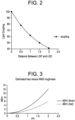
- FIG. 2 is a graph showing percentage light coupling versus distance between an LED and LGP edge.
- Figure 2 illustrates a relationship is shown which illustrates the drawbacks of conventional measures to solve challenges with PMMA. More specifically, Figure 2 illustrates a plot of light coupling versus LED to LGP distance assuming both are 2mm in height. It can be observed that the further the distance between LED and LGP, a less efficient light coupling is made between the LED and LGP.
- the CTE of PMMA is about 75E-6 C -1 and has relatively low thermal conductivity (0.2 W/m/K) while some glasses have a CTE of about 8E-6 C -1 and a thermal conductivity of 0.8 W/m/K.
- the CTE of other glasses can vary and such a disclosure should not limit the scope of the claims appended herewith.
- PMMA also has a transition temperature of about 105°C, and when used an LGP, a PMMA LGP material can become very hot whereby its low conductivity makes it difficult to dissipate heat. Accordingly, using glass instead of PMMA as a material for light guide plates provides benefits in this regard, but conventional glass has a relatively poor transmission compared to PMMA due mostly to iron and other impurities.
- glass light guide plates for use in backlight units can have one or more of the following attributes.
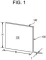
- FIG. 1 is a pictorial illustration of an exemplary embodiment of a light guide plate.
- an illustration is provided of an exemplary embodiment having a shape and structure of an exemplary light guide plate comprising a sheet of glass having a first face 110, which may be a front face, and a second face opposite the first face, which may be a back face.
- the first and second faces may have a height, H, and a width, W.
- the first and/or second face(s) may have a roughness that is less than 0.6 nm, less than 0.5 nm, less than 0.4 nm, less than 0.3 nm, less than 0.2 nm, less than 0.1 nm, or between about 0.1 nm and about 0.6 nm.
- the glass sheet may have a thickness, T, between the front face and the back face, where the thickness forms four edges.
- the thickness of the glass sheet may be less than the height and width of the front and back faces.
- the thickness of the plate may be less than 1.5% of the height of the front and/or back face.
- the thickness, T may be less than about 3 mm, less than about 2 mm, less than about 1 mm, or between about 0.1 mm to about 3 mm.
- the height, width, and thickness of the light guide plate may be configured and dimensioned for use in an LCD backlight application.
- a first edge 130 may be a light injection edge that receives light provided for example by a light emitting diode (LED).
- the light injection edge may scatter light within an angle less than 12.8 degrees full width half maximum (FWHM) in transmission.
- the light injection edge may be obtained by grinding the edge without polishing the light injection edge.
- the glass sheet may further comprise a second edge 140 adjacent to the light injection edge and a third edge opposite the second edge and adjacent to the light injection edge, where the second edge and/or the third edge scatter light within an angle of less than 12.8 degrees FWHM in reflection.
- the second edge 140 and/or the third edge may have a diffusion angle in reflection that is below 6.4 degrees.
- FIG. 1 shows a single edge 130 injected with light
- the claimed subject matter should not be so limited as any one or several of the edges of an exemplary embodiment 100 can be injected with light.
- the first edge 130 and its opposing edge can both be injected with light.
- Such an exemplary embodiment may be used in a display device having a large and or curvilinear width W. Additional embodiments may inject light at the second edge 140 and its opposing edge rather than the first edge 130 and/or its opposing edge.
- Thicknesses of exemplary display devices can be less than about 10 mm, less than about 9 mm, less than about 8 mm, less than about 7 mm, less than about 6 mm, less than about 5 mm, less than about 4 mm, less than about 3 mm, or less than about 2 mm.
- the glass composition of the glass sheet may comprise between 74-77 mol% SiO 2 , between 3-6 mol% Al 2 O 3 , and between 0-4 mol% B 2 O 3 , and less than 50 ppm iron (Fe) concentration. In some embodiments, there may be less than 25 ppm Fe, or in some embodiments the Fe concentration may be about 20 ppm or less. In various embodiments, the thermal conduction of the light guide plate 100 may be greater than 0.5 W/m/K. In additional embodiments, the glass sheet may be formed by a polished float glass, a fusion draw process, a slot draw process, a redraw process, or another suitable forming process.
- the LGP can be made from a glass comprising colorless oxide components selected from the glass formers SiO 2 , Al 2 O 3 , and B 2 O 3 .
- the exemplary glass may also include fluxes to obtain favorable melting and forming attributes.
- fluxes include alkali oxides (Li 2 O, Na 2 O, K 2 O, Rb 2 O and Cs 2 O) and alkaline earth oxides (MgO, CaO, SrO, ZnO and BaO).
- the glass may contain constituents in the range of 74-77 mol% SiO 2 , in the range of 3-6 mol% Al 2 O 3 , in the range of 0-3.5 mol% B 2 O 3 , and in the range of 4 to 7% alkali oxides, 11 to 16% alkaline earth oxides, or combinations thereof.
- SiO 2 can serve as the basic glass former.
- concentration of SiO 2 is greater than 74 mole percent to provide the glass with a density and chemical durability suitable for a display glasses or light guide plate glasses, and a liquidus temperature (liquidus viscosity), which allows the glass to be formed by a downdraw process (e.g., a fusion process).
- the SiO 2 concentration can be less than or equal to about 80 mole percent to allow batch materials to be melted using conventional, high volume, melting techniques, e.g., Joule melting in a refractory melter.
- the 20 Pa.s (200 poise) temperature (melting temperature) generally rises.
- the SiO 2 concentration is adjusted so that the glass composition has a melting temperature less than or equal to 1,750°C.
- the mol% of SiO 2 may be in the range of about 74 to about 77 mol%, or alternatively in the range of about 74 to about 76 mol%.
- Al 2 O 3 is another glass former used to make the glasses described herein. Higher mole percent Al 2 O 3 can improve the glass's annealing point and modulus.
- the mol% of Al 2 O 3 is in the range of about 3 to about 6 mol%, and may be in the range of about 4 to about 6 mol%, or in the range of about 5 to about 6 mol%. In other embodiments, the mol% of Al 2 O 3 may be about 5 to 6 mol%.
- B 2 O 3 is both a glass former and a flux that aids melting and lowers the melting temperature. It has an impact on both liquidus temperature and viscosity. Increasing B 2 O 3 can be used to increase the liquidus viscosity of a glass. To achieve these effects, the glass compositions of one or more embodiments may have B 2 O 3 concentrations that are equal to or greater than 0.1 mole percent; however, some compositions may have a negligible amount of B 2 O 3 . As discussed above with regard to SiO 2 , glass durability is very important for display applications. Durability can be controlled somewhat by elevated concentrations of alkaline earth oxides, and significantly reduced by elevated B 2 O 3 content.
- the mol% of B 2 O 3 is in the range of about 0% to about 3.5%, and may be in the range of about 0% to about 3%, or in the range of about 0% to about 2%.
- the glasses described herein may also include alkaline earth oxides.
- at least three alkaline earth oxides are part of the glass composition, e.g., MgO, CaO, and BaO, and, optionally, SrO.
- the alkaline earth oxides provide the glass with various properties important to melting, fining, forming, and ultimate use.
- the glass composition comprises MgO in an amount in the range of about 0 mol% to about 6 mol%, or in the range of about 2 mol% to about 4 mol%, or in the range of about 1 mol% to about 5 mol%, or in the range of about 2 mol% to about 5 mol%, or in the range of about 3 mol% to about 5 mol%.
- calcium oxide present in the glass composition can produce low liquidus temperatures (high liquidus viscosities), high annealing points and moduli, and CTE's in the most desired ranges for display and light guide plate applications. It also contributes favorably to chemical durability, and compared to other alkaline earth oxides, it is relatively inexpensive as a batch material.
- CaO increases the density and CTE.
- CaO may stabilize anorthite, thus decreasing liquidus viscosity.
- the CaO concentration can be between 2 and 5 mol%.
- the CaO concentration of the glass composition is in the range of about 2 mol% to about 4.5 mol%, or in the range of about 2.4 mol% to about 4.5 mol%.
- the glass composition comprises ZnO in an amount in the range of about 0 to about 3.5 mol%, or about 0 to about 3.01 mol%, or about 0 to about 2.0 mol%.
- the glass composition comprises from about 0.1 mol % to about 1.0 mol % titanium oxide; from about 0.1 mol % to about 1.0 mol % zirconium oxide; from about 0.1 mol % to about 1.0 mol % tin oxide; from about 0.1 mol % to about 1.0 mol % molybdenum oxide; from about 0.1 mol % to about 1.0 mol % cerium oxide.
- the glass compositions described herein can also include various contaminants associated with batch materials and/or introduced into the glass by the melting, fining, and/or forming equipment used to produce the glass.
- the glasses can also contain SnO 2 either as a result of Joule melting using tin-oxide electrodes and/or through the batching of tin containing materials, e.g., SnO 2 , SnO, SnCO 3 , SnC 2 O 2 , etc.
- an "alkali-free glass” is a glass having a total alkali concentration which is less than or equal to 0.1 mole percent, where the total alkali concentration is the sum of the Na 2 O, K 2 O, and Li 2 O concentrations.
- the glass comprises Li 2 O in the range of about 0 to about 3.0 mol%, in the range of about 0 to about 2.0 mol%, in the range of about 0 to about 1.0 mol%.
- the glass compositions described herein can have one or more or all of the following compositional characteristics: (i) an As 2 O 3 concentration of at most 0.05 to 1.0 mol%; (ii) an Sb 2 O 3 concentration of at most 0.05 to 1.0 mol%; (iii) a SnO 2 concentration of at most 0.25 to 3.0 mol%.
- As 2 O 3 is an effective high temperature fining agent for display glasses, and in some embodiments described herein, As 2 O 3 is used for fining because of its superior fining properties. However, As 2 O 3 is poisonous and requires special handling during the glass manufacturing process. Accordingly, in certain embodiments, fining is performed without the use of substantial amounts of As 2 O 3 , i.e., the finished glass has at most 0.05 mole percent As 2 O 3 . In one embodiment, no As 2 O 3 is purposely used in the fining of the glass. In such cases, the finished glass will typically have at most 0.005 mole percent As 2 O 3 as a result of contaminants present in the batch materials and/or the equipment used to melt the batch materials.
- Sb 2 O 3 is also poisonous and requires special handling.
- Sb 2 O 3 raises the density, raises the CTE, and lowers the annealing point in comparison to glasses that use As 2 O 3 or SnO 2 as a fining agent.
- fining is performed without the use of substantial amounts of Sb 2 O 3 , i.e., the finished glass has at most 0.05 mole percent Sb 2 O 3 .
- no Sb 2 O 3 is purposely used in the fining of the glass. In such cases, the finished glass will typically have at most 0.005 mole percent Sb 2 O 3 as a result of contaminants present in the batch materials and/or the equipment used to melt the batch materials.
- the concentration of SnO 2 in the finished glass is less than or equal to 0.25 mole percent, in the range of about 0.07 to about 0.11 mol%, in the range of about 0 to about 2 mol%, or from about 0 to about 3 mol%.
- Tin fining can be used alone or in combination with other fining techniques if desired.
- tin fining can be combined with halide fining, e.g., bromine fining.
- halide fining e.g., bromine fining.
- Other possible combinations include, but are not limited to, tin fining plus sulfate, sulfide, cerium oxide, mechanical bubbling, and/or vacuum fining. It is contemplated that these other fining techniques can be used alone.
- maintaining the (MgO+CaO+SrO+BaO)/Al 2 O 3 ratio and individual alkaline earth concentrations within the ranges discussed above makes the fining process easier to perform and more effective.
- the glass may comprise R x O where R is Li, Na, K, Rb, Cs, and x is 2, or R is Zn, Mg, Ca, Sr or Ba, and x is 1.
- R x O - Al 2 O 3 > 0.
- R x O/Al 2 O 3 is between 0 and 10, between 0 and 5, greater than 1, or between 3.5 and 4.5, or between 2 and 6, or between 3 and 5.
- Al 2 O 3 - R 2 O is between -2 and 0.5.
- exemplary glasses can have low concentrations of elements that produce visible absorption when in a glass matrix.
- Such absorbers include transition elements such as Ti, V, Cr, Mn, Fe, Co, Ni and Cu, and rare earth elements with partially-filled f-orbitals, including Ce, Pr, Nd, Sm, Eu, Tb, Dy, Ho, Er and Tm.
- transition elements such as Ti, V, Cr, Mn, Fe, Co, Ni and Cu
- rare earth elements with partially-filled f-orbitals including Ce, Pr, Nd, Sm, Eu, Tb, Dy, Ho, Er and Tm.
- Fe, Cr and Ni the most abundant in conventional raw materials used for glass melting are Fe, Cr and Ni.
- Iron is a common contaminant in sand, the source of SiO 2 , and is a typical contaminant as well in raw material sources for aluminum, magnesium and calcium.
- Chromium and nickel are typically present at low concentration in normal glass raw materials, but can be present in various ores of sand and must be controlled at a low concentration. Additionally, chromium and nickel can be introduced via contact with stainless steel, e.g., when raw material or cullet is jaw-crushed, through erosion of steel-lined mixers or screw feeders, or unintended contact with structural steel in the melting unit itself.
- the concentration of iron in some embodiments can be specifically less than 50ppm, more specifically less than 40ppm, or less than 25 ppm, and the concentration of Ni and Cr can be specifically less than 5 ppm, and more specifically less than 2ppm. In further embodiments, the concentration of all other absorbers listed above may be less than 1ppm for each.
- transition metal oxides that do not cause absorption from 300 nm to 650 nm and that have absorption bands ⁇ about 300 nm will prevent network defects from forming processes and will prevent color centers (e.g., absorption of light from 300 nm to 650 nm) post UV exposure when curing ink since the bond by the transition metal oxide in the glass network will absorb the light instead of allowing the light to break up the fundamental bonds of the glass network.
- exemplary embodiments can include any one or combination of the following transition metal oxides to minimize UV color center formation: from about 0.1 mol % to about 4.0 mol % zinc oxide; from about 0.1 mol % to about 1.0 mol % titanium oxide; from about 0.1 mol % to about 1.0 mol % vanadium oxide; from about 0.1 mol % to about 1.0 mol % niobium oxide; from about 0.1 mol % to about 1.0 mol % manganese oxide; from about 0.1 mol % to about 2.0 mol % zirconium oxide; from about 0.1 mol % to about 1.0 mol % arsenic oxide; from about 0.1 mol % to about 1.0 mol % tin oxide; from about 0.1 mol % to about 1.0 mol % molybdenum oxide; from about 0.1 mol % to about 1.0 mol % antimony oxide; from about 0.1 mol % to about 1.0 mol % cerium oxide
- the valence and coordination state of iron in a glass matrix can also be affected by the bulk composition of the glass.
- iron redox ratio has been examined in molten glasses in the system SiO 2 - K 2 O - Al 2 O 3 equilibrated in air at high temperature. It was found that the fraction of iron as Fe 3+ increases with the ratio K 2 O / (K 2 O + Al 2 O 3 ), which in practical terms will translate to greater absorption at short wavelengths.
- FIG. 3 is a graph showing the estimated light leakage in dB/m versus RMS roughness of an LGP.
- surface scattering plays a role in LGPs as light is bouncing many times on the surfaces thereof.
- the curve depicted in FIG. 3 illustrates light leakage in dB/m as a function of the RMS roughness of the LGP.
- FIG. 3 shows that, to get below 1dB/m, the surface quality needs to be better than about 0.6 nm RMS.
- This level of roughness can be achieved by either using fusion draw process or float glass followed by polishing.
- Such a model assumes that roughness acts like a Lambertian scattering surface which means that we are only considering high spatial frequency roughness.
- roughness should be calculated by considering the power spectral density and only take into account frequencies that are higher than about 20 microns -1 .
- Surface roughness may be measured by atomic force microscopy (AFM); white light interferometry with a commercial system such as those manufactured by Zygo; or by laser confocal microscopy with a commercial system such as those provided by Keyence.
- the scattering from the surface may be measured by preparing a range of samples identical except for the surface roughness, and then measuring the internal transmittance of each as described below. The difference in internal transmission between samples is attributable to the scattering loss induced by the roughened surface.
- UV light can also be used.
- light extraction features are often made by white printing dots on glass and UV is used to dry the ink.
- extraction features can be made of a polymer layer with some specific structure on it and requires UV exposure for polymerization. It has been discovered that UV exposure of glass can significantly affect transmission.
- a filter can be used during glass processing of the glass for an LGP to eliminate all wavelengths below about 400 nm.
- One possible filter consists in using the same glass as the one that is currently exposed.
- Glass waviness is somewhat different from roughness in the sense that it is much lower frequency (in the mm or larger range). As such, waviness does not contribute to extracting light since angles are very small but it modifies the efficiency of the extraction features since the efficiency is a function of the light guide thickness. Light extraction efficiency is, in general, inversely proportional to the waveguide thickness. Therefore, to keep high frequency image brightness fluctuations below 5% (which is the human perception threshold that resulted from our sparkle human perception analysis), the thickness of the glass needs to be constant within less than 5%. Exemplary embodiments can have an A-side waviness of less than 0.3 um, less than 0.2 um, less than 1 um, less than 0.08 um, or less than 0.06 um.
- FIG. 4 is a graph showing an expected coupling (without Fresnel losses ) as a function of distance between the LGP and LED for a 2mm thick LED's coupled into a 2mm thick LGP.
- light injection in an exemplary embodiment usually involves placing the LGP in direct proximity to one or more light emitting diodes (LEDs).
- LEDs light emitting diodes
- efficient coupling of light from an LED to the LGP involves using LED with a thickness or height that is less than or equal to the thickness of the glass.
- the distance from the LED to the LGP can be controlled to improve LED light injection.
- the distance should be ⁇ about 0.5mm to keep coupling > about 80%.
- plastic such as PMMA
- putting the LGP in physical contact with the LED's is somewhat problematic.
- a minimum distance is needed to let the material expand.
- LEDs tend to heat up significantly and, in case of physical contact, PMMA can get close to its Tg (105° C for PMMA). The temperature elevation that was measured when putting PMMA in contact with LED's was about 50°C close by the LEDs.
- a plurality of the edges of the LGP may have a mirror polish to improve LED coupling and TIR. In some embodiments, three of the four edges have a mirror polish.
- exemplary scattering angles can be ⁇ 20 degrees, ⁇ 19 degrees, ⁇ 18 degrees, ⁇ 17 degrees, ⁇ 16 degrees, ⁇ 14 degrees, ⁇ 13 degrees, ⁇ 12 degrees, ⁇ 11 degrees, or ⁇ 10 degrees.
- exemplary diffusion angles in reflection can be, but are not limited to, ⁇ 15 degrees, ⁇ 14 degrees, ⁇ 13 degrees, ⁇ 12 degrees, ⁇ 11 degrees, ⁇ 10 degrees, ⁇ 9 degrees, ⁇ 8 degrees, ⁇ 7 degrees, ⁇ 6 degrees, ⁇ 5 degrees, ⁇ 4 degrees, or ⁇ 3 degrees.
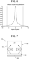
- FIG. 6 is a graph showing an expected angular energy distribution calculated from surface topology.
- the typical texture of a grinded only edge is illustrated where roughness amplitude is relatively high (on the order of 1nm) but special frequencies are relatively low (on the order of 20 microns) resulting in a low scattering angle.
- this figure illustrates the expected angular energy distribution calculated from the surface topology.
- scattering angle can be much less than 12.8 degrees full width half maximum (FWHM).
- a surface in terms of surface definition, can be characterized by a local slope distribution ⁇ (x,y) that can be calculated, for instance, by taking the derivative of the surface profile.
- FIG. 7 is a pictorial illustration showing total internal reflection of light at two adjacent edges of a glass LGP.
- light injected into a first edge 130 can be incident on a second edge 140 adjacent to the injection edge and a third edge 150 adjacent to the injection edge, where the second edge 140 is opposite the third edge 150.
- the second and third edges may also have a low roughness so that the incident light undergoes total internal reflectance (TIR) from the two edges adjacent the first edge.
- TIR total internal reflectance
- light may leak from each of those edges, thereby making the edges of an image appear darker.
- light may be injected into the first edge 130 from an array of LED's 200 positioned along the first edge 130.
- LCD panels One attribute of LCD panels is the overall thickness. In conventional attempts to make thinner structures, lack of sufficient stiffness has become a serious problem. Stiffness, however, can be increased with an exemplary glass LGP since the elastic modulus of glass is considerably larger than that of PMMA. In some embodiments, to obtain a maximum benefit from a stiffness point of view, all elements of the panel can be bonded together at the edge.
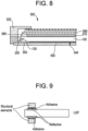
- FIG. 8 is a cross sectional illustration of an exemplary LCD panel with a LGP in accordance with one or more embodiments.
- an exemplary embodiment of a panel structure 500 is provided.
- the structure comprises an LGP 100 mounted on a back plate 550 through which light can travel and be redirected toward the LCD or an observer.
- a structural element 555 may affix the LGP 100 to the back plate 550, and create a gap between the back face of the LGP and a face of the back plate.
- a reflective and/or diffusing film 540 may be positioned between the back face of the LGP 100 and the back plate 550 to send recycled light back through the LGP 100.
- a plurality of LEDs, organic light emitting diodes (OLEDs), or cold cathode fluorescent lamps (CCFLs) may be positioned adjacent to the light injection edge 130 of the LGP, where the LEDs have the same width as the thickness of the LGP 100, and are at the same height as the LGP 100. In other embodiments, the LEDs have a greater width and/or height as the thickness of the LGP 100.
- Conventional LCDs may employ LEDs or CCFLs packaged with color converting phosphors to produce white light.
- One or more backlight film(s) 570 may be positioned adjacent the front face of the LGP 100.
- An LCD panel 580 may also be positioned above the front face of the LGP 100 with a structural element 585, and the backlight film(s) 570 may be located in the gap between the LGP 100 and LCD panel 580. Light from the LGP 100 can then pass through the film 570, which can backscatter high angle light and reflect low angle light back toward the reflector film 540 for recycling and may serve to concentrate light in the forward direction (e.g., toward the user).
- a bezel 520 or other structural member may hold the layers of the assembly in place.
- a liquid crystal layer (not shown) may be used and may comprise an electro-optic material, the structure of which rotates upon application of an electric field, causing a polarization rotation of any light passing through it.
- the angular light filters disclosed herein can be paired with a transparent light guide plate in a transparent display device.
- the LGP can be bonded to the structure (using optically clear adhesive OCA or pressure sensitive adhesive PSA) where the LGP is placed in optical contact with some of the structural elements of the panel. In other words, some of the light may leak out of the light guide through the adhesive. This leaked light can become scattered or absorbed by those structural elements.
- the first edge where the LEDs are coupled into the LGP and the two adjacent edges where the light needs to be reflected in TIR can avoid this problem if properly prepared.
- Exemplary widths and heights of the LGP generally depend upon the size of the respective LCD panel. It should be noted that embodiments of the present subject matter are applicable to any size LCD panel whether small ( ⁇ 40" diagonal) or large (>40" diagonal) displays. Exemplary dimensions for LGPs include, but are not limited to, 20", 30", 40", 50", 60" diagonal or more.
- FIG. 9 is a cross sectional illustration of an exemplary LCD panel with a LGP according to another embodiment.
- additional embodiments can utilize a reflective layer. Losses in some embodiments can be minimized by inserting a reflective surface between the LGP and the epoxy by either metalizing the glass with, for instance, silver or inkjet print with reflective ink.
- highly reflective films such as Enhanced Specular Reflector films (made by 3M) may be laminated with the LGP.
- FIG. 10 is a pictorial illustration showing an LGP with adhesion pads according to additional embodiments.
- adhesion pads instead of a continuous adhesive can be used in which the pads 600 are shown as a series of dark squares.
- the illustrated embodiment can employ 5 x 5 mm square pads every 50 mm to provide sufficient adhesion where extracted light is less than 4%.
- the pads 600 may be circular or another polygon in form and may be provided in any array or spacing and such a description should not limit the scope of the claims appended herewith.
- Exemplary light-guide plates described herein have ⁇ y ⁇ 0.015, ⁇ y ⁇ 0.005, ⁇ y ⁇ 0.003, or ⁇ y ⁇ 0.001.
- an image filter can be applied that will attenuate blue close to the edge where light gets injected. This may require shifting the color of the LEDs themselves to keep the right white color.
- pixel geometry can be used to address color shift by adjusting the surface ratio of the RGB pixels in the panel and increasing the surface of the blue pixels far away from the edge where the light gets injected.
- the density of exemplary glass compositions can range from about 2.5 gm/cc @ 20 C to about 2.7 gm/cc @ 20 C, from about 2.513 gm/cc @ 20 C to about 2.7 gm/cc @ 20 C, or from about 2.5 gm/cc @ 20 C to about 2.613 gm/cc @ 20 C.
- CTEs (0-300 °C) for exemplary embodiments can range from about 30 x 10-7/ °C to about 95 x 10-7/ °C, from about 55 x 10-7/ °C to about 64 x 10-7/ °C, or from about 55 x 10-7/ °C to about 80 x 10-7/ °C.
- the CTE is about 55.7 x 10⁻⁷/ °C and in another embodiment the CTE is about 69 x 10-7/°C.
- the LGP has a width of at least about 1270 mm and a thickness of between about 0.5 mm and about 3.0 mm, wherein the transmittance of the LGP is at least 80% per 500 mm.
- the thickness of the LGP is between about 1 mm and about 8 mm, and the width of the plate is between about 1100 mm and about 1300 mm.
- the ion exchange process can involve subjecting the glass sheet to a molten salt bath including KNO 3 , preferably relatively pure KNO 3 for one or more first temperatures within the range of about 400 - 500 °C and/or for a first time period within the range of about 1-24 hours, such as, but not limited to, about 8 hours. It is noted that other salt bath compositions are possible and would be within the skill level of an artisan to consider such alternatives. Thus, the disclosure of KNO 3 should not limit the scope of the claims appended herewith.
- Such an exemplary ion exchange process can produce an initial CS at the surface of the glass sheet, an initial DOL into the glass sheet, and an initial CT within the glass sheet. Annealing can then produce a final CS, final DOL and final CT as desired.
- the liquidus temperature of the glass in terms of °C was measured using the standard gradient boat liquidus method of ASTM C829-81. This involves placing crushed glass particles in a platinum boat, placing the boat in a furnace having a region of gradient temperatures, heating the boat in an appropriate temperature region for 24 hours, and determining by means of microscopic examination the highest temperature at which crystals appear in the interior of the glass. More particularly, the glass sample is removed from the Pt boat in one piece, and examined using polarized light microscopy to identify the location and nature of crystals which have formed against the Pt and air interfaces, and in the interior of the sample. Because the gradient of the furnace is very well known, temperature vs. location can be well estimated, within 5-10 °C.
- Raw materials appropriate for producing exemplary glasses include commercially available sands as sources for SiO2; alumina, aluminum hydroxide, hydrated forms of alumina, and various aluminosilicates, nitrates and halides as sources for Al2O3; boric acid, anhydrous boric acid and boric oxide as sources for B2O3; periclase, dolomite (also a source of CaO), magnesia, magnesium carbonate, magnesium hydroxide, and various forms of magnesium silicates, aluminosilicates, nitrates and halides as sources for MgO; limestone, aragonite, dolomite (also a source of MgO), wolastonite, and various forms of calcium silicates, aluminosilicates, nitrates and halides as sources for CaO; and oxides, carbonates, nitrates and halides of strontium and barium.
- sands as sources for SiO2
- tin can be added as SnO2, as a mixed oxide with another major glass component (e.g., CaSnO3), or in oxidizing conditions as SnO, tin oxalate, tin halide, or other compounds of tin known to those skilled in the art.
- another major glass component e.g., CaSnO3
- oxidizing conditions as SnO, tin oxalate, tin halide, or other compounds of tin known to those skilled in the art.
- nearly all stable elements in the periodic table are present in glasses at some level, either through low levels of contamination in the raw materials, through high-temperature erosion of refractories and precious metals in the manufacturing process, or through deliberate introduction at low levels to fine tune the attributes of the final glass.
- zirconium may be introduced as a contaminant via interaction with zirconium-rich refractories.
- platinum and rhodium may be introduced via interactions with precious metals.
- iron may be introduced as a tramp in raw materials, or deliberately added to enhance control of gaseous inclusions.
- manganese may be introduced to control color or to enhance control of gaseous inclusions.
- hydroxyl ions can also be introduced through the combustion products from combustion of natural gas and related hydrocarbons, and thus it may be desirable to shift the energy used in melting from burners to electrodes to compensate.
- Reduced multivalents can also be used to control the tendency of exemplary glasses to form SO2 blisters. While not wishing to be bound to theory, these elements behave as potential electron donors that suppress the electromotive force for sulfate reduction.
- Electrons may be "added” through reduced multivalents. For example, an appropriate electron-donating half reaction for ferrous iron (Fe2+) is expressed as 2Fe2+ ⁇ 2Fe3+ + 2e-
- halides may be present at various levels, either as contaminants introduced through the choice of raw materials, or as deliberate components used to eliminate gaseous inclusions in the glass.
- halides may be incorporated at a level of about 0.4 mol% or less, though it is generally desirable to use lower amounts if possible to avoid corrosion of off-gas handling equipment.
- the concentrations of individual halide elements are below about 200ppm by weight for each individual halide, or below about 800ppm by weight for the sum of all halide elements.
- Such oxides include, but are not limited to, TiO2, ZrO2, HfO2, Nb2O5, Ta2O5, MoO3, WO3, ZnO, In2O3, Ga2O3, Bi2O3, GeO2, PbO, SeO3, TeO2, Y2O3, La2O3, Gd2O3, and others known to those skilled in the art.
- colorless oxides can be added to a level of up to about 2 mol% to 3 mol% without unacceptable impact to annealing point, T35k-Tliq or liquidus viscosity.
- some embodiments can include any one or combination of the following transition metal oxides to minimize UV color center formation: from about 0.1 mol % to about 4.0 mol % zinc oxide; from about 0.1 mol % to about 1.0 mol % titanium oxide; from about 0.1 mol % to about 1.0 mol % vanadium oxide; from about 0.1 mol % to about 1.0 mol % niobium oxide; from about 0.1 mol % to about 1.0 mol % manganese oxide; from about 0.1 mol % to about 2.0 mol % zirconium oxide; from about 0.1 mol % to about 1.0 mol % arsenic oxide; from about 0.1 mol % to about 1.0 mol % tin oxide; from about 0.1 mol % to about 1.0 mol % molybdenum oxide; from about 0.1 mol % to about 1.0 mol % antimony oxide; from about 0.1 mol % to about 1.0 mol % cerium oxide
- an exemplary glass can contain from 0.1 mol% to less than or no more than about 4.0 mol% of any combination of zinc oxide, titanium oxide, vanadium oxide, niobium oxide, manganese oxide, zirconium oxide, arsenic oxide, tin oxide, molybdenum oxide, antimony oxide, and cerium oxide.
- Some exemplary embodiments include a glass article or sheet comprising SiO 2 in the range of about 74 to 77 mol%, Al 2 O 3 in the range of about 3 to 6 mol%, R 2 O in the range of about 4 to 7 mol%, of which 0 to 2 mol% is Na 2 O, B 2 O 3 in the range of about 0 to 3.5 mol%, ZrO 2 in the range of about 0 to 1.7 mol%, RO in the range of about 11 to 16 mol%, and ZnO in the range of about 0 to 4 mol%.
- the impurity level must be very low, on the order of ⁇ 60 ppm total Fe, Cr and Ni. In some embodiments, the impurity levels should be Fe ⁇ 20 ppm, Cr ⁇ 5 ppm, and Ni ⁇ 5 ppm.
- Fe 3+ has its absorption peaks in UV wavelengths, and it will affect the blue end of the visible spectrum; however, this is very small compared to the effect of Fe 2+ .
- the oxidation state of a glass melt is controlled by all the oxides in it, for example, alkali ions make the SnO 2 more stable than SnO, thus giving a more oxidized melt.
- alkali ions make the SnO 2 more stable than SnO, thus giving a more oxidized melt.
- the redox state of the iron in the glass can be affected, and the induced absorption by iron in visible wavelengths can be minimized.
- other oxides also induce absorption, and NiO and Cr 2 O 3 are also of concern as they are present as impurities in raw materials.
- NiO has an absorption band that can change considerably with compositions and ranges from 430nm to 630nm
- Cr 2 O 3 has absorption peaks at 450nm and 650nm.
- FIG. 11 is a graph depicting transmission values of exemplary glass compositions doped individually with Fe 2 O 3 , NiO, and Cr 2 O 3 .
- Fe 2 O 3 exemplary glass compositions doped individually with Fe 2 O 3 , NiO, and Cr 2 O 3 .
- FIG. 11 it can be observed that iron reduced blue and red transmission while nickel and chromium together have a large effect at 450nm.
- the effect of NiO appears to be more pronounced in these RO modified glasses as compared to R 2 O modified glasses, thus it is of great importance to reduce the amount of NiO in exemplary glasses.
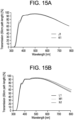
- FIG. 12 is a graph depicting transmission values of exemplary glass compositions with varied R 2 O types, and Table 1 provides, for a fixed base glass, a variation of alkali modifiers.
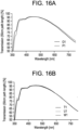
- FIG. 13 is a graph depicting transmission values for glasses in Table 2, and Table 2 provides Al 2 O 3 /R 2 O variations from 0.79 to 1.28 in a base glass.
- Exemplary fining agents include, but are not limited to SnO 2 and Sb 2 O 3 which can change the tilt of the respective transmission curve by improving red transmission and slightly decreasing blue transmission, as antimony affects the oxidation state of the system and thus changes the iron oxidation state which is the major driver for transmission.
- the invention further relates to a glass article comprising a glass sheet with a front face having a width and a height, a back face opposite the front face, and a thickness between the front face and back face, forming four edges around the front and back faces, wherein the glass sheet comprises greater than about 74 mol % SiO 2 , between about 3 mol% to about 6 mol% Al 2 O 3 , between about 0 mol% to about 3.5 mol% B 2 O 3 , between about 4 mol% to about 7 mol% R 2 O, wherein R is any one or more of Li, Na, K, Rb, Cs, between about 11 mol% to about 16 mol% RO, wherein R is any one or more of Mg, Ca, Sr or Ba, wherein R 2 O/RO is between about 0.38 to about 0.53.
Landscapes
- Chemical & Material Sciences (AREA)
- Engineering & Computer Science (AREA)
- Materials Engineering (AREA)
- Life Sciences & Earth Sciences (AREA)
- Chemical Kinetics & Catalysis (AREA)
- General Chemical & Material Sciences (AREA)
- Geochemistry & Mineralogy (AREA)
- Organic Chemistry (AREA)
- Crystallography & Structural Chemistry (AREA)
- Dispersion Chemistry (AREA)
- Ceramic Engineering (AREA)
- Physics & Mathematics (AREA)
- General Physics & Mathematics (AREA)
- Optics & Photonics (AREA)
- Glass Compositions (AREA)
Claims (16)
- Article en verre comprenant :une feuille de verre avec une face avant ayant une largeur et une hauteur, une face arrière opposée à la face avant, et une épaisseur entre la face avant et la face arrière, formant quatre bords autour des faces avant et arrière,l'article en verre comprenant :plus de 74 moles % de SiO2,entre 3 moles % et 6 moles % de Al2O3,entre 0 moles % et 3,5 moles % de B2O3,entre 4 moles % et 7 moles % de R2O, R étant un ou plusieurs quelconques parmi Li, Na, K, Rb, Cs,Al2O3 - R2O étant entre -2 et 0,5, etR2O/RO étant entre 0,38 et 0,53, R étant un quelconque parmi Mg, Ca, Sr ou Ba.
- Article en verre comprenant :une feuille de verre avec une face avant ayant une largeur et une hauteur, une face arrière opposée à la face avant et une épaisseur entre la face avant et la face arrière, formant quatre bords autour des faces avant et arrière,l'article en verre comprenant :plus de 74 moles % de SiO2,entre 3 moles % et 6 moles % de Al2O3,entre 0 mole % et 3,5 moles % de B2O3,entre 4 moles % et 7 moles % de R2O, R étant un ou plusieurs quelconques parmi Li, Na, K, Rb, Cs, entre 11 moles % et 16 moles % de RO, R étant un ou plusieurs quelconques parmi Mg, Ca, Sr ou Ba, R2O/RO étant entre 0,38 et 0,53.
- Article en verre de l'une quelconque des revendications 1-2, dans lequel le verre a une variation chromatique < 0,005.
- Article en verre de l'une quelconque des revendications 1-2, dans lequel le verre a une température de déformation supérieure à 600 °C.
- Article en verre de l'une quelconque des revendications 1-2, dans lequel le verre a une température de recuit supérieure à 650 °C.
- Article en verre de l'une quelconque des revendications 1-2, dans lequel le verre a un CTE entre 55 x 10-7/ °C et 64 x 10-7/ °C.
- Article en verre de l'une quelconque des revendications 1-2, dans lequel le verre a une densité entre 2,51 gm/cc @ 20 C et 2,64 gm/cc @ 20 C.
- Article en verre de l'une quelconque des revendications 1-2, l'article en verre étant une plaque guide de lumière.
- Article en verre de la revendication 8, dans lequel l'épaisseur de la plaque est entre 0,2 mm et 8 mm.
- Article en verre de la revendication 8, dans lequel la plaque guide de lumière est fabriquée à partir d'un procédé de fusion-étirage, d'un procédé d'étirage à partir d'une fente ou d'un procédé de flottage.
- Article en verre de l'une quelconque des revendications 1-2, dans lequel le verre comprend moins de 20 ppm de chaque Co, Ni, et Cr.
- Article en verre de l'une quelconque des revendications 1-2, dans lequel le verre comprend moins de 20 ppm au total de Co, Ni, et Cr.
- Article en verre de l'une quelconque des revendications 1-2, dans lequel le verre comprend moins de 20 ppm de Fe, moins de 5 ppm de Co, et moins de 5 ppm de Ni.
- Article en verre de l'une quelconque des revendications 1-2, dans lequel Al2O3/R2O < 1.
- Article en verre de l'une quelconque des revendications 1-2, dans lequel Al2O3 est égal à R2O +/- 0,05.
- Article en verre de l'une quelconque des revendications 1-2, dans lequel la transmittance à 450 nm avec une longueur d'au moins 500 mm est supérieure ou égale à 85 %, la transmittance à 550 nm avec une longueur d'au moins 500 mm est supérieure ou égale à 90 %, ou la transmittance à 630 nm avec une longueur d'au moins 500 mm est supérieure ou égale à 85 %, et leurs combinaisons.
Applications Claiming Priority (2)
| Application Number | Priority Date | Filing Date | Title |
|---|---|---|---|
| US201662395406P | 2016-09-16 | 2016-09-16 | |
| PCT/US2017/051483 WO2018053078A1 (fr) | 2016-09-16 | 2017-09-14 | Verres à transmission élevée comprenant des oxydes alcalino-terreux en tant que modificateur |
Publications (2)
| Publication Number | Publication Date |
|---|---|
| EP3512815A1 EP3512815A1 (fr) | 2019-07-24 |
| EP3512815B1 true EP3512815B1 (fr) | 2023-12-20 |
Family
ID=59955721
Family Applications (1)
| Application Number | Title | Priority Date | Filing Date |
|---|---|---|---|
| EP17772247.7A Active EP3512815B1 (fr) | 2016-09-16 | 2017-09-14 | Verres à transmission élevée comprenant des oxydes alcalino-terreux en tant que modificateur |
Country Status (7)
| Country | Link |
|---|---|
| US (1) | US11161769B2 (fr) |
| EP (1) | EP3512815B1 (fr) |
| JP (1) | JP7145147B2 (fr) |
| KR (1) | KR102549608B1 (fr) |
| CN (1) | CN109715574B (fr) |
| TW (1) | TWI738867B (fr) |
| WO (1) | WO2018053078A1 (fr) |
Families Citing this family (3)
| Publication number | Priority date | Publication date | Assignee | Title |
|---|---|---|---|---|
| CN116282901A (zh) * | 2016-09-13 | 2023-06-23 | Agc株式会社 | 高频器件用玻璃基板和高频器件用电路基板 |
| JP7133563B2 (ja) | 2017-03-31 | 2022-09-08 | コーニング インコーポレイテッド | 高透過ガラス |
| US11680005B2 (en) * | 2020-02-12 | 2023-06-20 | Owens-Brockway Glass Container Inc. | Feed material for producing flint glass using submerged combustion melting |
Citations (2)
| Publication number | Priority date | Publication date | Assignee | Title |
|---|---|---|---|---|
| WO2017070066A1 (fr) * | 2015-10-22 | 2017-04-27 | Corning Incorporated | Lunettes à transmission élevée |
| WO2018031892A1 (fr) * | 2016-08-11 | 2018-02-15 | Corning Incorporated | Procédé et appareil pour unité stratifiée de rétroéclairage |
Family Cites Families (42)
| Publication number | Priority date | Publication date | Assignee | Title |
|---|---|---|---|---|
| US5122671A (en) * | 1989-08-28 | 1992-06-16 | Lockheed Missiles & Space Company, Inc. | Terbium activated silicate luminescent glasses for use in converting x-ray radiation into visible radiation |
| US5120970A (en) * | 1989-08-28 | 1992-06-09 | Lockheed Missiles & Space Company, Inc. | X-ray image intensifier tube and x-ray conversion screen containing terbium activated silicate luminescent glasses |
| US5250096A (en) | 1992-04-07 | 1993-10-05 | At&T Bell Laboratories | Sol-gel method of making multicomponent glass |
| JP4320823B2 (ja) * | 1998-02-27 | 2009-08-26 | 旭硝子株式会社 | 基板用ガラス組成物 |
| JP4795651B2 (ja) * | 2003-06-06 | 2011-10-19 | ショット アクチエンゲゼルシャフト | 特に蛍光ランプへ用いる高耐薬品性紫外線吸収ガラス、製造方法、及び使用方法 |
| KR101290866B1 (ko) * | 2005-08-17 | 2013-07-29 | 코닝 인코포레이티드 | 고변형점 유리 |
| US7833919B2 (en) * | 2006-02-10 | 2010-11-16 | Corning Incorporated | Glass compositions having high thermal and chemical stability and methods of making thereof |
| US8187715B2 (en) * | 2008-05-13 | 2012-05-29 | Corning Incorporated | Rare-earth-containing glass material and substrate and device comprising such substrate |
| JP5354445B2 (ja) | 2008-06-25 | 2013-11-27 | 日本電気硝子株式会社 | 金属被覆用ガラス及び半導体封止材料 |
| WO2010023419A1 (fr) | 2008-09-01 | 2010-03-04 | Saint-Gobain Glass France | Procede d'obtention de verre et verre obtenu |
| US8445394B2 (en) * | 2008-10-06 | 2013-05-21 | Corning Incorporated | Intermediate thermal expansion coefficient glass |
| WO2011145661A1 (fr) * | 2010-05-19 | 2011-11-24 | 旭硝子株式会社 | Verre pour le renforcement chimique et plaque de verre pour le dispositif d'affichage |
| CN103025673B (zh) | 2010-06-30 | 2016-10-26 | Ocv智识资本有限责任公司 | 生产高强度和高模量纤维的玻璃组合物 |
| EP2729425B1 (fr) | 2011-07-04 | 2016-05-04 | AGC Glass Europe | Feuille de verre flotte a haute transmission energetique |
| JP2013043795A (ja) | 2011-08-23 | 2013-03-04 | Nippon Electric Glass Co Ltd | 強化ガラス及びその製造方法 |
| AU2012328981B2 (en) | 2011-10-25 | 2016-07-07 | Corning Incorporated | Alkaline earth alumino-silicate glass compositions with improved chemical and mechanical durability |
| JP6084577B2 (ja) | 2011-12-20 | 2017-02-22 | Hoya株式会社 | Hdd用ガラス基板 |
| US9162919B2 (en) * | 2012-02-28 | 2015-10-20 | Corning Incorporated | High strain point aluminosilicate glasses |
| JP2013212943A (ja) | 2012-03-30 | 2013-10-17 | Avanstrate Inc | フラットパネルディスプレイ用ガラス基板の製造方法 |
| KR102029530B1 (ko) * | 2012-12-21 | 2019-10-07 | 코닝 인코포레이티드 | 개선된 총 피치 안정성을 갖는 유리 |
| JP5914453B2 (ja) | 2012-12-28 | 2016-05-11 | AvanStrate株式会社 | ディスプレイ用ガラス基板およびその製造方法 |
| EP2991941A2 (fr) * | 2013-04-29 | 2016-03-09 | Corning Incorporated | Boîtier de module photovoltaïque |
| WO2015033866A1 (fr) | 2013-09-03 | 2015-03-12 | 日本電気硝子株式会社 | Plaque de guidage de lumière |
| WO2015068741A1 (fr) | 2013-11-08 | 2015-05-14 | 旭硝子株式会社 | Plaque de verre, unité de panneau de guidage de lumière, dispositif d'émission de lumière planaire, et dispositif d'affichage à cristaux liquides |
| US10144198B2 (en) * | 2014-05-02 | 2018-12-04 | Corning Incorporated | Strengthened glass and compositions therefor |
| US9670088B2 (en) * | 2014-05-20 | 2017-06-06 | Corning Incorporated | Scratch resistant glass and method of making |
| JPWO2015186486A1 (ja) | 2014-06-04 | 2017-05-25 | 旭硝子株式会社 | 導光板用のガラス板 |
| US9902644B2 (en) | 2014-06-19 | 2018-02-27 | Corning Incorporated | Aluminosilicate glasses |
| WO2016017558A1 (fr) | 2014-08-01 | 2016-02-04 | 旭硝子株式会社 | Verre à haute transparence |
| JP2017188187A (ja) | 2014-08-28 | 2017-10-12 | 旭硝子株式会社 | ガラス板 |
| JPWO2016031345A1 (ja) | 2014-08-28 | 2017-06-15 | 旭硝子株式会社 | ガラス板 |
| CN105487163A (zh) | 2014-10-03 | 2016-04-13 | 旭硝子株式会社 | 导光板用玻璃板 |
| JP2016074570A (ja) | 2014-10-08 | 2016-05-12 | 旭硝子株式会社 | ガラス板、および、それを用いたエッジライト型面状照明装置 |
| JP6635314B2 (ja) | 2014-11-05 | 2020-01-22 | 日本電気硝子株式会社 | ガラス及びガラス板 |
| KR102242786B1 (ko) | 2014-11-27 | 2021-04-21 | 엘지디스플레이 주식회사 | 백라이트 유닛 및 이를 구비하는 표시장치 |
| TWI515479B (zh) | 2014-12-09 | 2016-01-01 | 揚昇照明股份有限公司 | 顯示裝置及背光模組 |
| CN105384337A (zh) | 2015-11-04 | 2016-03-09 | 芜湖东旭光电装备技术有限公司 | 玻璃、导光板、背光模组、液晶面板、液晶显示终端及玻璃的制备方法 |
| CN205193310U (zh) | 2015-11-06 | 2016-04-27 | 乐视致新电子科技(天津)有限公司 | 导光模组及包括导光模组的显示装置 |
| CN105601102A (zh) | 2015-12-23 | 2016-05-25 | 芜湖东旭光电装备技术有限公司 | 高碱硅铝酸盐玻璃、导光板、背光模组、液晶面板、液晶显示终端及玻璃的制备方法 |
| CN105502932B (zh) | 2015-12-30 | 2018-02-09 | 东旭科技集团有限公司 | 一种导光板玻璃用组合物及其用途 |
| CN108603652A (zh) | 2016-02-10 | 2018-09-28 | 康宁股份有限公司 | 复合导光板 |
| CN105527760B (zh) | 2016-02-22 | 2018-11-30 | 京东方科技集团股份有限公司 | 显示模组及显示装置 |
-
2017
- 2017-09-14 WO PCT/US2017/051483 patent/WO2018053078A1/fr unknown
- 2017-09-14 EP EP17772247.7A patent/EP3512815B1/fr active Active
- 2017-09-14 JP JP2019515240A patent/JP7145147B2/ja active Active
- 2017-09-14 CN CN201780057360.7A patent/CN109715574B/zh active Active
- 2017-09-14 KR KR1020197010865A patent/KR102549608B1/ko active IP Right Grant
- 2017-09-14 US US16/333,823 patent/US11161769B2/en active Active
- 2017-09-15 TW TW106131701A patent/TWI738867B/zh active
Patent Citations (2)
| Publication number | Priority date | Publication date | Assignee | Title |
|---|---|---|---|---|
| WO2017070066A1 (fr) * | 2015-10-22 | 2017-04-27 | Corning Incorporated | Lunettes à transmission élevée |
| WO2018031892A1 (fr) * | 2016-08-11 | 2018-02-15 | Corning Incorporated | Procédé et appareil pour unité stratifiée de rétroéclairage |
Also Published As
| Publication number | Publication date |
|---|---|
| CN109715574B (zh) | 2022-04-05 |
| US20190256403A1 (en) | 2019-08-22 |
| KR102549608B1 (ko) | 2023-06-29 |
| CN109715574A (zh) | 2019-05-03 |
| US11161769B2 (en) | 2021-11-02 |
| KR20190055156A (ko) | 2019-05-22 |
| TWI738867B (zh) | 2021-09-11 |
| EP3512815A1 (fr) | 2019-07-24 |
| WO2018053078A1 (fr) | 2018-03-22 |
| JP2019529316A (ja) | 2019-10-17 |
| TW201817692A (zh) | 2018-05-16 |
| JP7145147B2 (ja) | 2022-09-30 |
Similar Documents
| Publication | Publication Date | Title |
|---|---|---|
| US11001521B2 (en) | Aluminosilicate glasses | |
| EP3365595B1 (fr) | Plaque de guide de lumière à transmission élevée | |
| US11746038B2 (en) | High transmission glasses | |
| US20190185367A1 (en) | Method and apparatus for laminated backlight unit | |
| EP3512815B1 (fr) | Verres à transmission élevée comprenant des oxydes alcalino-terreux en tant que modificateur | |
| US11254601B2 (en) | Low alkali high transmission glasses | |
| TWI841418B (zh) | 高透光玻璃 |
Legal Events
| Date | Code | Title | Description |
|---|---|---|---|
| STAA | Information on the status of an ep patent application or granted ep patent |
Free format text: STATUS: UNKNOWN |
|
| STAA | Information on the status of an ep patent application or granted ep patent |
Free format text: STATUS: THE INTERNATIONAL PUBLICATION HAS BEEN MADE |
|
| PUAI | Public reference made under article 153(3) epc to a published international application that has entered the european phase |
Free format text: ORIGINAL CODE: 0009012 |
|
| STAA | Information on the status of an ep patent application or granted ep patent |
Free format text: STATUS: REQUEST FOR EXAMINATION WAS MADE |
|
| 17P | Request for examination filed |
Effective date: 20190411 |
|
| AK | Designated contracting states |
Kind code of ref document: A1 Designated state(s): AL AT BE BG CH CY CZ DE DK EE ES FI FR GB GR HR HU IE IS IT LI LT LU LV MC MK MT NL NO PL PT RO RS SE SI SK SM TR |
|
| AX | Request for extension of the european patent |
Extension state: BA ME |
|
| DAV | Request for validation of the european patent (deleted) | ||
| DAX | Request for extension of the european patent (deleted) | ||
| STAA | Information on the status of an ep patent application or granted ep patent |
Free format text: STATUS: EXAMINATION IS IN PROGRESS |
|
| 17Q | First examination report despatched |
Effective date: 20221004 |
|
| GRAP | Despatch of communication of intention to grant a patent |
Free format text: ORIGINAL CODE: EPIDOSNIGR1 |
|
| STAA | Information on the status of an ep patent application or granted ep patent |
Free format text: STATUS: GRANT OF PATENT IS INTENDED |
|
| INTG | Intention to grant announced |
Effective date: 20230721 |
|
| GRAS | Grant fee paid |
Free format text: ORIGINAL CODE: EPIDOSNIGR3 |
|
| GRAA | (expected) grant |
Free format text: ORIGINAL CODE: 0009210 |
|
| STAA | Information on the status of an ep patent application or granted ep patent |
Free format text: STATUS: THE PATENT HAS BEEN GRANTED |
|
| AK | Designated contracting states |
Kind code of ref document: B1 Designated state(s): AL AT BE BG CH CY CZ DE DK EE ES FI FR GB GR HR HU IE IS IT LI LT LU LV MC MK MT NL NO PL PT RO RS SE SI SK SM TR |
|
| REG | Reference to a national code |
Ref country code: GB Ref legal event code: FG4D |
|
| REG | Reference to a national code |
Ref country code: CH Ref legal event code: EP |
|
| REG | Reference to a national code |
Ref country code: DE Ref legal event code: R096 Ref document number: 602017077718 Country of ref document: DE |
|
| REG | Reference to a national code |
Ref country code: IE Ref legal event code: FG4D |
|
| PG25 | Lapsed in a contracting state [announced via postgrant information from national office to epo] |
Ref country code: GR Free format text: LAPSE BECAUSE OF FAILURE TO SUBMIT A TRANSLATION OF THE DESCRIPTION OR TO PAY THE FEE WITHIN THE PRESCRIBED TIME-LIMIT Effective date: 20240321 |
|
| REG | Reference to a national code |
Ref country code: LT Ref legal event code: MG9D |
|
| PG25 | Lapsed in a contracting state [announced via postgrant information from national office to epo] |
Ref country code: LT Free format text: LAPSE BECAUSE OF FAILURE TO SUBMIT A TRANSLATION OF THE DESCRIPTION OR TO PAY THE FEE WITHIN THE PRESCRIBED TIME-LIMIT Effective date: 20231220 |
|
| REG | Reference to a national code |
Ref country code: NL Ref legal event code: MP Effective date: 20231220 |
|
| PG25 | Lapsed in a contracting state [announced via postgrant information from national office to epo] |
Ref country code: ES Free format text: LAPSE BECAUSE OF FAILURE TO SUBMIT A TRANSLATION OF THE DESCRIPTION OR TO PAY THE FEE WITHIN THE PRESCRIBED TIME-LIMIT Effective date: 20231220 |
|
| PG25 | Lapsed in a contracting state [announced via postgrant information from national office to epo] |
Ref country code: LT Free format text: LAPSE BECAUSE OF FAILURE TO SUBMIT A TRANSLATION OF THE DESCRIPTION OR TO PAY THE FEE WITHIN THE PRESCRIBED TIME-LIMIT Effective date: 20231220 Ref country code: GR Free format text: LAPSE BECAUSE OF FAILURE TO SUBMIT A TRANSLATION OF THE DESCRIPTION OR TO PAY THE FEE WITHIN THE PRESCRIBED TIME-LIMIT Effective date: 20240321 Ref country code: FI Free format text: LAPSE BECAUSE OF FAILURE TO SUBMIT A TRANSLATION OF THE DESCRIPTION OR TO PAY THE FEE WITHIN THE PRESCRIBED TIME-LIMIT Effective date: 20231220 Ref country code: ES Free format text: LAPSE BECAUSE OF FAILURE TO SUBMIT A TRANSLATION OF THE DESCRIPTION OR TO PAY THE FEE WITHIN THE PRESCRIBED TIME-LIMIT Effective date: 20231220 Ref country code: BG Free format text: LAPSE BECAUSE OF FAILURE TO SUBMIT A TRANSLATION OF THE DESCRIPTION OR TO PAY THE FEE WITHIN THE PRESCRIBED TIME-LIMIT Effective date: 20240320 |
|
| REG | Reference to a national code |
Ref country code: AT Ref legal event code: MK05 Ref document number: 1642348 Country of ref document: AT Kind code of ref document: T Effective date: 20231220 |
|
| PG25 | Lapsed in a contracting state [announced via postgrant information from national office to epo] |
Ref country code: NL Free format text: LAPSE BECAUSE OF FAILURE TO SUBMIT A TRANSLATION OF THE DESCRIPTION OR TO PAY THE FEE WITHIN THE PRESCRIBED TIME-LIMIT Effective date: 20231220 |