EP3512433B1 - Dispositif d'échantillonnage de fluide - Google Patents
Dispositif d'échantillonnage de fluide Download PDFInfo
- Publication number
- EP3512433B1 EP3512433B1 EP17771380.7A EP17771380A EP3512433B1 EP 3512433 B1 EP3512433 B1 EP 3512433B1 EP 17771380 A EP17771380 A EP 17771380A EP 3512433 B1 EP3512433 B1 EP 3512433B1
- Authority
- EP
- European Patent Office
- Prior art keywords
- housing
- outer housing
- sampling
- gas
- reservoir
- Prior art date
- Legal status (The legal status is an assumption and is not a legal conclusion. Google has not performed a legal analysis and makes no representation as to the accuracy of the status listed.)
- Active
Links
- 238000005070 sampling Methods 0.000 title claims description 109
- 239000012530 fluid Substances 0.000 title claims description 89
- 239000000463 material Substances 0.000 claims description 20
- 238000004891 communication Methods 0.000 claims description 13
- 239000012528 membrane Substances 0.000 claims description 4
- 230000004044 response Effects 0.000 claims description 2
- 230000035699 permeability Effects 0.000 claims 2
- 238000005086 pumping Methods 0.000 claims 1
- 239000007789 gas Substances 0.000 description 43
- 210000001035 gastrointestinal tract Anatomy 0.000 description 27
- 239000002775 capsule Substances 0.000 description 22
- 239000003795 chemical substances by application Substances 0.000 description 9
- 238000010791 quenching Methods 0.000 description 9
- 230000000171 quenching effect Effects 0.000 description 9
- 238000000034 method Methods 0.000 description 8
- 230000033001 locomotion Effects 0.000 description 7
- 201000010099 disease Diseases 0.000 description 6
- 208000037265 diseases, disorders, signs and symptoms Diseases 0.000 description 6
- 239000002184 metal Substances 0.000 description 6
- 230000008901 benefit Effects 0.000 description 5
- 239000007788 liquid Substances 0.000 description 5
- 238000005192 partition Methods 0.000 description 5
- 229920000642 polymer Polymers 0.000 description 5
- 239000002861 polymer material Substances 0.000 description 5
- 210000000813 small intestine Anatomy 0.000 description 5
- 230000036541 health Effects 0.000 description 4
- 230000001580 bacterial effect Effects 0.000 description 3
- 239000000203 mixture Substances 0.000 description 3
- 230000000717 retained effect Effects 0.000 description 3
- 241000736262 Microbiota Species 0.000 description 2
- 210000000436 anus Anatomy 0.000 description 2
- 230000000694 effects Effects 0.000 description 2
- 238000003780 insertion Methods 0.000 description 2
- 230000037431 insertion Effects 0.000 description 2
- 239000000155 melt Substances 0.000 description 2
- 230000008569 process Effects 0.000 description 2
- 210000002784 stomach Anatomy 0.000 description 2
- 230000009747 swallowing Effects 0.000 description 2
- 102000004190 Enzymes Human genes 0.000 description 1
- 108090000790 Enzymes Proteins 0.000 description 1
- UFHFLCQGNIYNRP-UHFFFAOYSA-N Hydrogen Chemical compound [H][H] UFHFLCQGNIYNRP-UHFFFAOYSA-N 0.000 description 1
- 239000004696 Poly ether ether ketone Substances 0.000 description 1
- 239000004698 Polyethylene Substances 0.000 description 1
- WYTGDNHDOZPMIW-RCBQFDQVSA-N alstonine Natural products C1=CC2=C3C=CC=CC3=NC2=C2N1C[C@H]1[C@H](C)OC=C(C(=O)OC)[C@H]1C2 WYTGDNHDOZPMIW-RCBQFDQVSA-N 0.000 description 1
- 239000012491 analyte Substances 0.000 description 1
- 238000004458 analytical method Methods 0.000 description 1
- 238000013459 approach Methods 0.000 description 1
- 238000009360 aquaculture Methods 0.000 description 1
- 244000144974 aquaculture Species 0.000 description 1
- 230000004323 axial length Effects 0.000 description 1
- 230000007147 bacterial dysbiosis Effects 0.000 description 1
- 230000004888 barrier function Effects 0.000 description 1
- JUPQTSLXMOCDHR-UHFFFAOYSA-N benzene-1,4-diol;bis(4-fluorophenyl)methanone Chemical compound OC1=CC=C(O)C=C1.C1=CC(F)=CC=C1C(=O)C1=CC=C(F)C=C1 JUPQTSLXMOCDHR-UHFFFAOYSA-N 0.000 description 1
- 239000000560 biocompatible material Substances 0.000 description 1
- 239000000090 biomarker Substances 0.000 description 1
- 230000015556 catabolic process Effects 0.000 description 1
- 230000006037 cell lysis Effects 0.000 description 1
- 230000008859 change Effects 0.000 description 1
- 238000012512 characterization method Methods 0.000 description 1
- 210000001072 colon Anatomy 0.000 description 1
- 230000006835 compression Effects 0.000 description 1
- 238000007906 compression Methods 0.000 description 1
- 238000006731 degradation reaction Methods 0.000 description 1
- 230000001419 dependent effect Effects 0.000 description 1
- 238000009792 diffusion process Methods 0.000 description 1
- 238000007599 discharging Methods 0.000 description 1
- 238000004090 dissolution Methods 0.000 description 1
- 239000003814 drug Substances 0.000 description 1
- 229940079593 drug Drugs 0.000 description 1
- 210000001198 duodenum Anatomy 0.000 description 1
- 238000001839 endoscopy Methods 0.000 description 1
- 238000005516 engineering process Methods 0.000 description 1
- 230000007613 environmental effect Effects 0.000 description 1
- 230000002550 fecal effect Effects 0.000 description 1
- 210000003608 fece Anatomy 0.000 description 1
- 239000006260 foam Substances 0.000 description 1
- 230000006870 function Effects 0.000 description 1
- 230000002496 gastric effect Effects 0.000 description 1
- 244000005709 gut microbiome Species 0.000 description 1
- 239000001257 hydrogen Substances 0.000 description 1
- 229910052739 hydrogen Inorganic materials 0.000 description 1
- 210000003405 ileum Anatomy 0.000 description 1
- 238000003384 imaging method Methods 0.000 description 1
- 230000003993 interaction Effects 0.000 description 1
- 230000000968 intestinal effect Effects 0.000 description 1
- 238000002955 isolation Methods 0.000 description 1
- 238000002844 melting Methods 0.000 description 1
- 230000008018 melting Effects 0.000 description 1
- 244000005700 microbiome Species 0.000 description 1
- 239000012229 microporous material Substances 0.000 description 1
- 238000012986 modification Methods 0.000 description 1
- 230000004048 modification Effects 0.000 description 1
- 210000003928 nasal cavity Anatomy 0.000 description 1
- 229920002530 polyetherether ketone Polymers 0.000 description 1
- -1 polyethylene Polymers 0.000 description 1
- 229920000573 polyethylene Polymers 0.000 description 1
- 229920001296 polysiloxane Polymers 0.000 description 1
- 239000011148 porous material Substances 0.000 description 1
- 238000011160 research Methods 0.000 description 1
- 238000007789 sealing Methods 0.000 description 1
- 230000011664 signaling Effects 0.000 description 1
- 229910052710 silicon Inorganic materials 0.000 description 1
- 239000010703 silicon Substances 0.000 description 1
- 229910001220 stainless steel Inorganic materials 0.000 description 1
- 239000010935 stainless steel Substances 0.000 description 1
- 239000000126 substance Substances 0.000 description 1
- 210000001215 vagina Anatomy 0.000 description 1
Images


Classifications
-
- A—HUMAN NECESSITIES
- A61—MEDICAL OR VETERINARY SCIENCE; HYGIENE
- A61B—DIAGNOSIS; SURGERY; IDENTIFICATION
- A61B10/00—Other methods or instruments for diagnosis, e.g. instruments for taking a cell sample, for biopsy, for vaccination diagnosis; Sex determination; Ovulation-period determination; Throat striking implements
- A61B10/0045—Devices for taking samples of body liquids
-
- A—HUMAN NECESSITIES
- A61—MEDICAL OR VETERINARY SCIENCE; HYGIENE
- A61B—DIAGNOSIS; SURGERY; IDENTIFICATION
- A61B10/00—Other methods or instruments for diagnosis, e.g. instruments for taking a cell sample, for biopsy, for vaccination diagnosis; Sex determination; Ovulation-period determination; Throat striking implements
- A61B10/0038—Devices for taking faeces samples; Faecal examination devices
-
- A—HUMAN NECESSITIES
- A61—MEDICAL OR VETERINARY SCIENCE; HYGIENE
- A61B—DIAGNOSIS; SURGERY; IDENTIFICATION
- A61B10/00—Other methods or instruments for diagnosis, e.g. instruments for taking a cell sample, for biopsy, for vaccination diagnosis; Sex determination; Ovulation-period determination; Throat striking implements
- A61B10/02—Instruments for taking cell samples or for biopsy
- A61B10/04—Endoscopic instruments
-
- A—HUMAN NECESSITIES
- A61—MEDICAL OR VETERINARY SCIENCE; HYGIENE
- A61B—DIAGNOSIS; SURGERY; IDENTIFICATION
- A61B10/00—Other methods or instruments for diagnosis, e.g. instruments for taking a cell sample, for biopsy, for vaccination diagnosis; Sex determination; Ovulation-period determination; Throat striking implements
- A61B10/0045—Devices for taking samples of body liquids
- A61B2010/0061—Alimentary tract secretions, e.g. biliary, gastric, intestinal, pancreatic secretions
-
- A—HUMAN NECESSITIES
- A61—MEDICAL OR VETERINARY SCIENCE; HYGIENE
- A61B—DIAGNOSIS; SURGERY; IDENTIFICATION
- A61B2562/00—Details of sensors; Constructional details of sensor housings or probes; Accessories for sensors
- A61B2562/16—Details of sensor housings or probes; Details of structural supports for sensors
- A61B2562/162—Capsule shaped sensor housings, e.g. for swallowing or implantation
Definitions
- GI gastrointestinal
- the composition and health of the GI tract are increasingly implicated in a wide range of disease conditions.
- the examination and characterization of the GI environment is of high interest.
- the GI tract is difficult to access, particularly the small intestinal section.
- the most common technique for examining the GI tract is through the use of endoscopic instruments, either from the mouth or nasal cavity or from the anus. But, such procedures are invasive, uncomfortable and require a trained physician to operate. Further, more distal regions of the small intestines are not accessible without very complex instrumentation and procedures.
- CE Capsule endoscopy
- Fluid samples may be analyzed for the presence of cells, enzymes, biomarkers, metabolome, and/or microbiota, for example.
- One particular area of promising research is in the examination of gut microbiota and its relation to health and disease. Specifically, there are numerous studies showing a connection of bacterial dysbiosis to disease state. Further there are many approaches towards treating disease by control of gut bacterial compositions. To date a large majority of work has been via the examination of fecal microbiota. However, it is well known that the bacterial composition in the small intestines differs from that of the feces. Further, the connection of microbiome to health and disease for many conditions is likely to be more overt in the small intestines.
- US 4,239,040A discloses a capsule for discharging drugs into a love body or collecting samples from the body and comprises an external cylinder having slidably mounted internal cylinder. The pre-amble of claim 1 is based on this document.
- US 2015/011874A1 discloses a device and method for an ingestible medical device with a rotatable element.
- US 5167626A discloses a medical capsule device for releasing a substance at a defined location in the gastrointestinal tract.
- WO 2016/042302A1 discloses a sampling device suitable for collecting a sample in an aquaculture environment, enclosed system or in the gastrointestinal tract of a human or an animal.
- a fluid sampling device configured to sample fluids in an environment.
- a fluid sampling device may be configured as a swallowable capsule that samples fluids in the GI tract.
- capsules according to this disclosure may be selectively controlled to sample fluids in predetermined regions of the GI tract.
- a fluid sampling device includes an outer housing formed as a capsule, i.e., configured for swallowing by a patient, such as a mammalian patient.
- the fluid sampling device may be configured to sample fluids in the GI tract.
- fluid sampling devices according to this disclosure may configured for insertion into a bodily cavity, or may be implanted or otherwise placed in the body.
- a swallowable capsule may include an outer housing defining a capsule volume and an inner housing defining a sampling reservoir.
- the inner housing may be movable within the capsule volume, relative to the outer housing.
- the inner housing may be movable along an axis of the capsule or rotatable about the axis.
- the inner housing may be selectively moveable between a sampling position, e.g., in which fluid passes through the outer housing and the inner housing to enter the sampling reservoir, and a sealed position, e.g., in which fluid does not enter and/or exit the sampling reservoir.
- the inner housing may be biased toward the sealed position, e.g., by a biasing member applying a biasing force on the inner housing, inside the housing.
- An actuator may be positioned to provide a force that counters and overcomes the biasing force, to move the inner housing to the sampling position.
- the biasing member may be a spring or a deformable material.
- the actuator may be a gas generator, an electro-mechanical actuator, or a mechanical actuator, by way of non-limiting example.
- an interior of the inner housing e.g., a sampling reservoir
- an opening may be disposed through an outer housing comprising the exterior of the capsule and a passageway through the inner housing is connected to the opening in the sampling position.
- a hollow needle or similar feature may be in fluid communication with the opening in the exterior of the housing.
- Fluid sampling devices also may be configured to detect a location of the device in the GI tract, for example, to take a fluid sample from a certain portion of the GI tract, e.g., the duodenum, the ileum, the colon, etc.
- sampling devices may include a sensor that senses a position of the device.
- the sensor may sense a pH level of the environment surrounding the capsule.
- the sensor may also be operably connected to the actuator, such that upon sensing a predetermined pH level, the sensor emits a signal or otherwise triggers the actuator to move the interior housing from the sealed position to the sampling position.
- This disclosure relates generally to fluid sampling devices and systems, and although systems according to this disclosure will generally be described as being useful in intra-corporal, and more specifically, swallowable, devices, the concepts and systems described herein are not so limited. For example, concepts of this disclosure may be useful in devices that are inserted or otherwise placed in any cavity from which it is desirable to take a fluid sample. Stated simply, although certain embodiments and benefits will be described, other implementations, modifications, and/or benefits will be appreciated those having ordinary skill in the art, with the benefit of this disclosure.
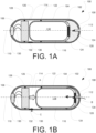
- FIGS. 1A and 1B are cross-sectional representations of a fluid sampling device 100 according to embodiments of this disclosure. As will be described in more detail below, FIG. 1A depicts the fluid sampling device 100 in a sealed position and FIG. 1B depicts the device 100 in a sampling position.
- the fluid sampling device 100 generally includes a housing 102 defining a size and shape of the device 100.
- the illustrated housing 102 is shaped like a capsule and includes a generally cylindrical sidewall 104 extending between a first end 106 and an opposite, second end 108, along an axis 110.
- the first end 106 and the second end 108 are generally dome-shaped to promote easier swallowing or insertion of the device 100.
- the housing 102 may take other shapes and sizes, depending upon the application and/or the desired effect.
- the housing 102 is a rigid housing that will not substantially deform when inside a body.
- the housing 102 may be made of one or more of many known materials, including but not limited to polymers, stainless steel, and the like.
- the housing is made of a biocompatible material that is approved and/or otherwise suitable for placement in a mammalian body.
- the housing may be formed from polyethylene, ABS, and/or PEEK.
- An opening 112 is formed as a hole through the housing 102.
- the opening 112 is a hole formed through the second end 108 of the housing 102, generally along the axis 110.
- the opening 112 may be offset from the axis 110 and/or may be located other than at the second end 108 of the housing 102.
- the opening 112 provides a fluid communication between the external environment of the device 100 and an inner volume 114 of the device 100, as defined by the housing 102.
- an inner rigid housing 116 is disposed in the inner volume 114 of the housing 102.
- the inner housing 116 is generally cylindrical, also disposed along the axis 110, and defines a sealed volume comprising a sampling reservoir 116.
- At least a portion of the inner rigid housing comprises a resealable portion 120.
- the sampling reservoir 116 may be accessed through the resealable portion 120.
- An outer circumference of the rigid housing 116 i.e., a circumference about the axis 110, is smaller than a circumference of an inner surface of the sidewall 104 of the outer housing 102. In this manner, the rigid housing 116 is movable within the housing 102, including along the axis 110.
- a seal 122 such as a wiper seal or an o-ring, is disposed to contact the inner surface of the sidewall 104 of the external housing 102 and an outer surface of the internal housing 116.
- the wiper seal 122 preferably restricts movement of the inner housing 116 in any direction other than along the axis 110.
- the wiper seal 122 may also partition the inner volume 114 of the device 100 into two volumes, namely, a first volume proximate the first end 106 of the device 100 and a second volume proximate the second end 108 of the device 100.
- additional seals may be provided at other locations along an axial length of the rigid housing 116. For example, such additional seals may prevent the rigid housing 116 from pivoting about the seal 122, relative to the axis 110.
- a biasing member 124 and an actuator 126 also are provided in the inner volume 114. More specifically, the biasing member is disposed proximate the second end 108 of the housing 102, and the actuator 126 is disposed proximate the first end 106 of the housing 102.
- the biasing member 124 may comprise a compressible material that compresses under a compressive force, but expands to its original position when the compressive force is removed.
- the biasing member 124 is chosen to bias the rigid housing 116 in a direction away from the second end 108 of the housing 102. That is, the biasing member maintains a predetermined spacing between the rigid housing 116 and the second end 108.
- the compressible material may include silicon, rubber, a gel, foam, or the like.
- the biasing member 124 may alternatively comprise a spring.
- Other biasing members may also be evident to those having skill in the art, with the benefit of this disclosure.
- the actuator 126 is configured to apply a force to the rigid housing 116 sufficient to overcome a biasing force provided by the biasing member 124, thereby moving the rigid housing 116 toward the second end 108 of the housing 102.
- the actuator 126 comprises a gas generating cell, such as a hydrogen generating cell.
- a seal 128 is provided to seal the gas generating cell 126 relative to an inner surface of the sidewall 104 of the housing 102.
- the seal 128 may be provided such that gas generated by the gas generating cell 126 is confined to an area of the internal volume 114 between the seal 128 and the seal 122 described above.
- the actuator 126 may be other than a gas generating cell.
- the actuator 126 may be a mechanical spring, such as a preloaded helical spring.
- the seal 128 may not be necessary.
- the device 100 also includes a sensor 130, proximate the first end 106 of the housing 102.
- the sensor 130 is operably connected to the actuator 126, e.g., via one more leads 132.
- the sensor may be a threshold sensor, for example, of a type that includes an enteric polymer material deposited over electrodes. Some example threshold sensors are illustrated in FIGS. 6-8 , discussed below.
- the sensor 130, or a portion of the sensor 130 is disposed on an external surface of the housing 102. In use, a raised pH and aqueous environment may cause the enteric polymer to erode. This exposes the electrodes and this condition is used as an electrical switch.
- the selection of polymer material, along with the possibility of layering different polymer materials, makes the switch sensitive to different pH environments and may be used to target different locations within the GI tract, for example.
- the illustrated example shows the sensor 130 disposed at the first end 106 of the housing, the sensor 130 may be disposed elsewhere on the housing 102.
- the fluid sampling device 100 also includes a hollow needle 134 connected to the opening 112.
- the hollow needle 134 protrudes generally inwardly from the second end 108 of the housing 102 into the volume 114.
- the hollow needle does not protrude as far from an inner surface of the end 108 as the biasing member 124.
- the hollow needle does not contact the inner, rigid housing 116.
- the biasing member is compressed toward the second end 108 of the housing 102, e.g., by the actuator 126 applying a pressure to the rigid housing 116 to move to the sampling position shown in FIG. 1B , the hollow needle may contact and pierce the resealable portion 120.
- the fluid sampling device 100 is in a sealed configuration in FIG. 1A , and in a sampling position in FIG. 1B .
- the fluid sampling device 100 is preferably ingested or otherwise inserted into the body in the sealed position of FIG. 1A .
- the device 100 is swallowed and traverses the gastrointestinal tract.
- the sensor 130 senses a position of the device 100 in the GI tract.
- the sensor 130 is a threshold sensor that identifies a predetermined location in the GI tract, e.g., by detecting a change in pH.
- the threshold sensor may include electrodes coated with a polymer material.
- the polymer material may be chosen to erode at a predetermined pH level, allowing contact of the electrodes and closing a circuit across the actuator.
- the actuator 126 is a gas generator. Accordingly, the gas generator begins to emit gas into the volume 114, generally in a direction toward the rigid housing 116, in response to the sensor 130 sensing a condition in the GI tract.
- an electrical signal may be created when the predetermined location is sensed by the sensor. This electrical signal is conveyed to the actuator 126, e.g., via an electronic circuit, by the leads 132.
- the rigid housing 116 As pressure builds in the housing 102 because of the gas generated by the gas generating actuator 126, the rigid housing 116 is forced to move axially toward the second end 108 of the housing 102. This movement is generally along arrow A illustrated in FIG. 1B . Eventually, the pressure on the rigid housing 116 along the direction of arrow A is sufficient to overcome the biasing force applied in an opposite direction by the biasing member 124. More specifically, the biasing member 124 begins to compress, and with continued compression of the biasing member 124, the resealable portion 120 of the rigid housing 116 comes in contact with the hollow needle 134 and the hollow needle 134 pierces through the resealable portion 120.
- the sampling reservoir 118 may be under vacuum condition, such that once impermeable membrane 120 is pierced by the hollow needle, fluid external to the device 100 rushes in to fill the space that is the sampling reservoir 118.
- the flow of fluids from the exterior of the device 100 into the sampling reservoir 118 is generally illustrated by Arrow B in FIG. 1B .
- the housing 102 also includes an exhaust 136.
- the exhaust 136 may be formed as one or a plurality of apertures or holes formed through a sidewall of the housing 102.
- the exhaust 136 may comprise at least a portion of the sidewall of the housing 102 that is made of a porous material that allows for passage of gaseous contents in the internal volume 114 of the housing 102 to a position outside the housing 102.
- some polymers are known through which vapor or gaseous materials may migrate, and a portion of the housing 102 may be formed from such a polymer to provide the exhaust.
- a dissipation film may be made from silicone, for example, and placed over a hole or other opening formed through the housing. Microporous materials also are known, and could form a portion of the exhaust 136.
- the exhaust 136 allows excess pressure in the internal volume 114 to be relieved, i.e., generally along arrow C.
- the exhaust 136 may comprise a vapor permeable polymer chosen to dissipate gas generated by the gas generator therethrough at a rate slower than the rate at which gas is produced (i.e., so sufficient pressure can build up in the volume 114 to move the rigid housing 116 against the biasing force).
- gas in the volume 114 escapes through the exhaust 136 until the force applied by the gas is overcome by the biasing force of the biasing member.
- the hollow needle becomes disengaged from the resealable portion 120, and the resealable portion re-seals, thereby sealing the fluids that entered the sampling reservoir 118 via the hollow needle 134 in the sampling reservoir.
- the device 100 After the device 100 exits the GI tract, it can be retrieved so fluid in the sampling reservoir can be removed and tested.
- FIG. 2 illustrates another fluid sampling device 200 according to another embodiment of this disclosure.
- the device 200 may also be configured to be swallowed by a user, e.g., to obtain fluid samples in the GI tract.
- the device 200 includes a capsule-shaped housing 202, generally including a cylindrical sidewall 204 extending between a dome-shaped first end 206 and an opposite, dome-shaped second end 208.
- An opening 210 is illustrated as being formed through the second end, although it could be formed at other locations on the housing 202.
- the device 200 includes a rigid housing 212 disposed in the housing 202.
- the rigid housing 212 defines a sampling reservoir 214.
- the rigid housing 212 also includes a resealable portion 216, similar to the resealable portion 120.
- a biasing member 218 also is provided to bias the rigid housing 212 away from the opening, and an actuator 220 is provided to selectively force the rigid housing 212 against the biasing member 218.
- the biasing member could include a compressible material, as in previous examples, in this example the biasing member 218 is illustrated as a helical spring.
- the actuator 220 instead of the gas generator of FIGS. 1A and 1B , the actuator 220 includes a compressed helical spring and a power cell 222 that is fixed relative to the outer housing 202. The spring comprising the actuator 220 is retained in the compressed position by a frangible wire 224.
- the frangible wire 224 is operably connected to the power cell 222, and the power cell is in electrical communication with a sensor 226, e.g., by one or more leads 228.
- the sensor 226 is positioned proximate the first end 206 of the housing 202, and disposed to monitor a location of the device 200.
- the sensor may include a pH sensor that monitors the pH of the surroundings.
- the device 200 may be swallowed and therefore traverses the GI tract.
- the sensor 226 determines that the device 200 has reached a predetermined position, e.g., by sensing a predetermined pH level, the sensor 226 generates an electrical signal that triggers the power cell 222 to apply concentrated electrical energy to the frangible wire 224. The energy is sufficient to weaken and break the frangible wire 224, thereby releasing the compressed spring.
- the spring 220 extends, contacts the rigid housing and imparts an axial motion on the rigid housing 212 with sufficient force to overcome the biasing force of the biasing member 218. As in the example described above with reference to FIGS.
- a hollow needle 230 pierces the resealable portion 216 of the rigid housing 212, creating a passageway from an exterior of the device 200 to the sampling reservoir 214.
- the initial force created upon breaking the frangible wire 224 is sufficient to overcome the biasing force of the biasing member 218 such that the rigid housing 212 contacts the needle 230 and the sampling reservoir 214 is filled. After the initial force, however, the biasing force of the biasing member 218 may be sufficient to return the device 200 back to a sealed position.
- a biasing force applied on the rigid housing 212 by the biasing member 218 is sufficient to counteract the spring 222 such that the hollow needle 230 is spaced from the rigid housing 212. Only the initial force generated by releasing the compressed spring 220 is sufficient to overcome the biasing force. In this manner, a sample is collected in the sampling reservoir 214, but the device 200 returns to a sealed position, which will prevent additional fluids from entering the fluid sampling reservoir 214 via the opening 210 and the hollow needle 230.
- FIG. 3 illustrates another example fluid sampling device 300 according to an example that is not an embodiment of this disclosure.
- the fluid sampling device 300 has many similarities to the sampling devices 100, 200 discussed above.
- the device 300 includes an outer housing 302 shaped like a capsule and including a generally cylindrical sidewall 304 extending between a first end 306 and the second and 308, generally along an axis 310.
- an opening 312 is formed proximate the second end 308 of the housing 302.
- a rigid housing 314 is disposed in the volume defined by the housing 302, and the rigid housing 314 defines a fluid sampling reservoir 316.
- FIG. 3 also illustrates a quenching agent 318 disposed in the fluid sampling reservoir 316.
- the quenching agent 318 is placed in the fluid sampling reservoir 316 prior to use.
- the quenching agent is provided to prevent degradation of the sample, once collected.
- the quenching agent may be selected to inhibit bacterial interaction and growth with the sample.
- the quenching agent may include cell lysis for example to preserve the DNA content of the sample taken.
- a quenching agent could be used in any of the fluid sampling reservoirs described herein.
- the rigid housing 314 also includes a resealable portion 320, and the device 300 includes an actuator 322, which may be a gas generating cell, a mechanical actuator, and/or an electromechanical actuator, for example.
- the device 300 also includes a sensor 324 connected to a power source 326 and electronics 328, e.g., by leads 330.
- the sensor 324 may be different from the threshold sensors discussed above.
- the sensor 324 may be an electronic-based pH sensor, such as an ISFET.
- the electronics 328 associated with the sensor 324 may include a timer, a microcontroller, and/or wireless communication components.
- the power source 326 may be batteries, or the like.
- the structure of the actuator 322, sensor 324, and additional, related components may be different from the example discussed above, the effect is generally the same.
- the sensor is disposed to sense a position, location, or predetermined environmental factor, and upon that sensing, the actuator 322 is driven to move the rigid housing 314 generally along an axis 310 toward the second end 308 of the housing 302.
- a hollow needle 332 is disposed in fluid communication with the opening 312, and as the rigid housing 314 is driven toward the second end 308, the hollow needle 332 will pierce through the resealable portion 320 of the rigid housing 314, thereby allowing fluid external to the device 300 to enter the fluid sampling reservoir 318.
- the hollow needle 332 is offset relative to the opening 312 by a channel 334 disposed in the end 308 of the housing 302.
- the channel 334 is formed as a path in the thickness of the material comprising the second end 308. More specifically, the channel is disposed between an inner surface 308a and outer surface 308b of the second end 308 of the housing 302.
- the channel 334 may comprise a serpentine or other tortuous path that may provide an increased resistance to flow, thereby extending the duration required of the sampling process.
- the flow path may provide a diffusion barrier and improved isolation of the sampling chamber relative to the outside environment.
- the channel 334 may obviate the need for a biasing member such as those described above.
- a biasing member such as the biasing member 124 or the biasing member 218 described above may be used.
- the hollow needle 332 may be required to extend further away from the inner surface 308a of the housing 302 than illustrated in FIG. 3 .
- FIG. 4 illustrates yet another example of a fluid sampling device 400 according to another embodiment of this disclosure.
- the fluid sampling device 400 includes an outer housing 402 shaped generally as a capsule.
- the housing 402 includes a generally cylindrical sidewall 404 for extending between a first end 406 and an opposite, second end 408, generally along an axis 410.
- an opening 412 is formed through the housing 402.
- the opening 412 is illustrated as a slot or similar elongate opening formed through the sidewall 404 of the housing 402.
- a rigid housing 414 is disposed in the volume defined by the housing 402 and is configured to move relative to the outer housing 402.
- An opening 416 is disposed in a sidewall of the rigid housing 414.
- the opening 416 is generally shaped and sized to correspond to the opening 412 in the outer housing 402.
- a propeller or fin 418 is disposed on an exterior of the inner, rigid housing 414.
- the fin 418 protrudes radially outwardly from an outer surface of the rigid housing 414 at an angle relative to the axis 410.
- the device 400 also includes an actuator, illustrated as a gas generator 420.
- the gas generator 420 is electrically connected to a sensor 422 for example, by leads 424.
- the gas generator 420 and the sensor 422 may be similar to those discussed above with reference to other embodiments of this disclosure. They generally function in the manner described above. More specifically, the sensor 422 is configured to sense a predetermined condition of an environment of the device 400, and upon sensing that condition, the gas generating cell 420 generates a gas.
- the gas is forced from the gas generating cell 420 generally in a direction along the axis 410, from the gas generating cell 420 toward the second end 408 of the housing 402.
- the gas preferably contacts the fin 418, which is canted relative to the axial direction.
- the force of the generated gas on the fin 418 imparts a rotational motion on the housing 414, causing the housing 414 to move generally in the direction of arrow 426, relative to the outer housing 402.
- the opening 416 formed in the sidewall of the rigid housing 414 comes in to registration with the opening 412 formed in the sidewall 404 of the outer housing 402. Accordingly, fluid in the environment of the device 400 is allowed to enter a sampling reservoir defined by the rigid housing 414.
- the rigid housing 414 may continue to rotate about the axis 410 until the opening 416 is no longer in registration with opening 412 in the housing 402, thereby resealing the inner housing 416.
- one or more seals may be used to ensure that the fluid sample obtained by the device 400 is retained in the rigid housing 414 after collection.
- a wiper seal or the like that circumscribes the opening 416 may protrude radially outwardly from the exterior surface of the rigid housing 414.
- the wiper seal may contact an inner surface of the sidewall 404 of the housing 402 such that the sampling reservoir defined by the rigid housing 414 is sealed.
- FIGS. 5A and 5B illustrate yet another embodiment of a fluid sampling device 500 according to this disclosure.
- the device 500 includes a housing 502 generally comprising a cylindrical sidewall 504 extending between a first end 506 and a second, opposite end 508.
- An opening 510 is formed in the second end 508 of the housing 502.
- the rigid inner housing is replaced with an expandable bladder 512.
- the expandable bladder 512 may be a collapsed bag, for example.
- the bladder 512 defines a fluid sampling reservoir 514, and a quenching agent 516 may be disposed in the fluid sampling reservoir 514.
- the device 500 also includes a sensor 518 electrically connected, e.g., via leads 520 to a controller 522.
- a pump 524 such as a piezoelectric pump is operably connected to the controller 522.
- the pump 524 is in fluid communication with the outside of the device 500 via an exhaust 526 disposed through the sidewall 504 at a location spaced from the second end 508 of the housing 502.
- the fluid sampling reservoir 514 is in fluid communication with an external environment of the device 500 through a hollow needle 528 and a fluid channel 530 in fluid communication with the opening 510.
- the senor 518 determines when the device 500 has reached a predetermined, sampling location. Sensing the predetermined location causes the pump 524 to begin to pump contents (e.g., gas or liquid) from inside the housing 502 to a position outside the device 500, i.e., via the exhaust 526. As the air is exhausted, generally in the direction of arrow 532, negative pressure is created inside the housing 502, causing the bladder 512 to expand. As the bladder 512 expands, fluid outside the device 500 is drawn into the fluid sampling reservoir 514 via the passageway formed by the opening 510, the channel 530, and the hollow needle 528.
- contents e.g., gas or liquid
- FIG. 5B illustrates a state in which the fluid reservoir 514 is filled with an analyte solution comprising the fluid sample from the capsule exterior and mixed with the quenching agent 516.
- a one-way valve may be disposed in communication with the opening 510, the channel 530, or the hollow needle 528, for example, to prevent the fluid sample retained in the expanded bladder 512 from exiting back through the opening 510, when the pump is turned off.
- FIG. 6 illustrates another example that is not an embodiment of a fluid sampling device 600 according to additional examples that are not embodiments of this disclosure.
- the device 600 includes a housing 602 including a sidewall 604, which may be a cylindrical sidewall, extending between a first end 606 and a second end 608.
- a partition 610 is provided that generally divides the inner volume defined by the housing 602 into two chambers, one proximate the first end 606 and the other proximate the second end 608.
- a movable member 612 arranged for axial movement relative to the housing 602 generally includes a shaft 614 extending axially through the partition 610.
- a first piston 616 is positioned between the first end 606 and the partition 610 and is sealed relative to an inner surface of the sidewall 604.
- a second piston 618 is positioned between the second end 608 and the partition 610, and is sealed relative to an inner surface.
- An opening 620 is formed through the housing 602 at the first end 606.
- the opening 620 fluidly connects an external environment of the device 600 with a sampling reservoir 622 via a passageway 624.
- the passageway is illustrated as a generally cylindrical channel extending along an axis of the device 600.
- the sampling reservoir 622 is defined by an inner surface of the sidewall 604, an inner surface of the first end 606, and the first piston 616.
- a gas generating cell 626 is provided as an actuator proximate the second end 608 of the housing 602.
- a gaseous output of the gas generating cell 626 is routed via a gas passageway 628 from the gas generating cell 626 to a side of the second piston 618 opposite the second end 608.
- the gas generated by the gas generating cell 626 forces the moveable member 612 toward the second end. 608.
- This movement of the moveable member 612 causes the sampling reservoir 622 to expand, creating a negative pressure.
- the negative pressure causes fluid external to the device 600 to enter the sampling reservoir 622 via the passageway 624.
- a one-way valve may be provided in communication with the passageway 624, to prevent fluid from exiting the sampling reservoir 622.
- vents 630, 632 also are provided, to allow movement of the moveable member 612.
- the two-piston configuration depicted in FIG. 6 provides one specific arrangement, which outlines the principle of operation. However, there are many other configurations possible.
- the actuator may be placed in the center of the device and one or more arm(s) connecting the two pistons 616, 618 may be positioned close to the inner surface of the sidewall 604.
- the device 600 may also include a sensor such as the sensors described above, to trigger the gas generating cell 626 to generate gas.
- the device may also include a controller and/or other electronics necessary to operation.
- FIGS. 7-9 illustrate examples that are not embodiments of thresholds sensors that may be used in examples that are not embodiments of this disclosure. More specifically, FIG. 7 illustrates a threshold sensor 700 that includes a first metal electrode 702 and a second metal electrode 704 spaced from the first metal electrode 702. For example, the first metal electrode 702 and the second metal electrode 704 may be electrically connected to leads, such as leads 132, 228, 330, 424, 520, discussed above.
- a pH-sensitive material 706 is disposed over the electrodes 702, 704 to prevent a galvanic connection between the metal electrodes 702, 704. The pH-sensitive material 706 is selected to melt or otherwise dissolve at a predetermined pH level, for example, a pH-level of greater than 6.
- the electrodes 702, 704 are exposed, and galvanic contact is made via the surrounding fluid. This galvanic contact may directly result in actuation of a gas generating cell, or trigger an active electronics circuit.
- the thickness of the pH sensitive layer may be varied in some examples that are not embodiments to create a predetermined delay to the moment of sampling. This may be useful to target different regions within the GI tract, for example.
- FIG. 8 illustrates another example that is not an embodiment of a threshold sensor 800.
- Threshold sensor 800 includes a first electrode 802 and a second electrode 804.
- the second electrode 804 is biased away from the first electrode 802 by a pH sensitive material 806.
- the pH sensitive material 806 melts or dissolves much like the pH sensitive material 806 of the sensor 800.
- melting or dissolution of the pH sensitive material 806 results in the second electrode 804 physically moving, to make a physical contact with the first electrode 802. More specifically, the pH sensitive material 806 puts the second electrode 804 forces the second electrode 804 away from the first electrode 802, such that when the pH-sensitive material 806 no longer present, the second electrode 804 returns to its unbiased position, contacting the first electrode 802.
- FIG. 9 illustrates yet another example of a threshold sensor 900 according to examples that are not embodiments of this.
- a first electrode 902 and a second electrode 904 are provided, spaced relative to each other.
- a pH-sensitive material 906 is disposed in the space between the first electrode 902 and the second electrode 904.
- the pH-sensitive material 906 is a pH-sensitive gel that absorb surrounding liquid if the pH value of that liquid exceeds a predetermined value. As the liquid is absorbed, a galvanic contact is formed between the first electrode 902 and the second electrode 904, thereby signaling that the surrounding environment of the sensor 900 has a predetermined pH value.
- Sensors such as those illustrated in FIGS. 7-9 are generally used to determine that an environment of the sensor has a predetermined pH because areas of the GI tract have discernable pH variations. For instance, a pH of the stomach is markedly different from a pH of the small intestine. Accordingly, by determining the pH, a capsule can readily be configured to sample fluids in the stomach or in the small intestine.
- sensors may be used to determine a position of fluid sampling devices according to this disclosure.
- a sensor may sense a position, e.g., using global positioning technology.
- a sensor may not be necessary at all.
- a clock or timer may be disposed in the fluid sampling device which may measure a time, e.g., since the capsule was swallowed, which is used to instead trigger fluid sampling.
- the device may not be swallowed.
- the fluid sampling device may be inserted into a bodily cavity, e.g., via the anus or vagina.
- a sensor may also not be necessary.
- the device may include a retrieval feature, i.e., for removing the device after retrieving the sample.
- a rigid or flexible structure like a handle or string, may be provided on an exterior of the device to promote retrieval.
- FIGS. 1A and 1B illustrate use of a gas generating cell with a compressible material biasing member
- FIG. 2 illustrates a spring actuator and a spring biasing member
- either of those embodiments could instead include a spring actuator and a compressible member biasing member or a gas generating cell actuator and a spring biasing member.
- different types of sensors e.g., the ISFET and threshold sensors, could be used in different embodiments than those illustrated.
- Other combinations although not explicitly stated herein, will be understood by those having ordinary skill in the art, with the benefit of this disclosure.
Landscapes
- Health & Medical Sciences (AREA)
- Life Sciences & Earth Sciences (AREA)
- Surgery (AREA)
- Molecular Biology (AREA)
- Animal Behavior & Ethology (AREA)
- Biomedical Technology (AREA)
- Heart & Thoracic Surgery (AREA)
- Medical Informatics (AREA)
- Pathology (AREA)
- Veterinary Medicine (AREA)
- Engineering & Computer Science (AREA)
- General Health & Medical Sciences (AREA)
- Public Health (AREA)
- Hematology (AREA)
- Nuclear Medicine, Radiotherapy & Molecular Imaging (AREA)
- Radiology & Medical Imaging (AREA)
- Measurement Of The Respiration, Hearing Ability, Form, And Blood Characteristics Of Living Organisms (AREA)
Claims (10)
- Dispositif (100) d'échantillonnage de contenu dans une cavité corporelle d'un patient, le dispositif (100) comprenant :un boîtier extérieur (102) comprenant une paroi latérale (104) s'étendant entre une première extrémité (106) et une seconde extrémité (108) espacées le long d'un axe à partir de la première extrémité (106) et une ouverture (112) s'étendant à travers la paroi latérale (104) à proximité de la seconde extrémité (108) ;un réservoir d'échantillonnage (118) comprenant un boîtier rigide (116) définissant un volume et une partie pouvant être rescellée (120), le réservoir d'échantillonnage (118) étant disposé dans le boîtier extérieur (102) et mobile à l'intérieur du boîtier extérieur (102), généralement le long de l'axe, entre une position scellée, relativement plus proche de la première extrémité (106) du boîtier extérieur (102), et une position d'échantillonnage, relativement plus proche de la seconde extrémité (108) du boîtier extérieur (102) ;un élément de sollicitation (124) disposé dans le boîtier extérieur (102) à proximité de la seconde extrémité (108) du boîtier (102) et configuré pour appliquer une force de sollicitation au réservoir d'échantillonnage (118) afin de solliciter le réservoir d'échantillonnage (118) vers la position scellée ;caractérisé en ce que le dispositif (100) comprend :une cellule de génération de gaz (126) disposée dans le boîtier extérieur (102) à proximité de la première extrémité (106) du boîtier extérieur (102) et configurée pour générer un gaz à un débit d'actionnement suffisant pour déplacer le réservoir d'échantillonnage (118) de la position scellée à la position d'échantillonnage, à l'encontre de la force de sollicitation ;un capteur (130) disposé pour détecter une condition d'un environnement externe au boîtier extérieur (102), le capteur (130) étant connecté électriquement à la cellule de génération de gaz (126) pour commander de manière sélective la cellule de génération de gaz (126) afin de générer le gaz ; etune aiguille creuse (134) fixée par rapport au boîtier extérieur (102) et en communication fluidique avec l'ouverture (112) s'étendant à travers la paroi latérale (104),dans lequel la partie pouvant être rescellée (120) du réservoir d'échantillonnage (118) est percée par l'aiguille creuse (134) lorsque le réservoir d'échantillonnage (118) est dans la position d'échantillonnage et la partie pouvant être rescellée (120) du réservoir d'échantillonnage (118) est espacée de l'aiguille creuse (134) lorsque le réservoir d'échantillonnage (118) est dans la position scellée.
- Dispositif (100) selon la revendication 1, comprenant en outre un échappement (136) dans le boîtier extérieur (102) à proximité de la cellule de génération de gaz (126).
- Dispositif (100) selon la revendication 2, dans lequel l'échappement (136) comprend une membrane perméable au gaz présentant une perméabilité au gaz qui permet au gaz de s'écouler à travers la membrane perméable au gaz à un débit inférieur au débit d'actionnement auquel la cellule de génération de gaz génère du gaz.
- Dispositif (100) selon la revendication 1, dans lequel le capteur (130) comprend un matériau sensible au pH qui provoque un signal au niveau du capteur (130) lorsqu'un pH de l'environnement dépasse un pH seuil.
- Dispositif selon la revendication 1, comprenant en outre un évent dans le boîtier extérieur (102) à proximité de la cellule de génération de gaz.
- Dispositif selon la revendication 5, dans lequel l'évent comprend une membrane perméable au gaz présentant une perméabilité au gaz inférieure à un débit auquel la cellule de génération de gaz (126) génère du gaz.
- Dispositif selon la revendication 1, dans lequel le capteur (130) comprend un capteur de seuil sensible à un pH de seuil de l'environnement.
- Dispositif selon la revendication 1, dans lequel l'aiguille creuse (134) comprend un canal reliant de manière fluidique l'aiguille creuse (134) à l'ouverture.
- Dispositif (400) selon la revendication 5, dans lequel :le réservoir d'échantillonnage comprend un réservoir cylindrique rigide (414), une ailette (418) s'étendant radialement vers l'extérieur à partir d'une surface extérieure du boîtier cylindrique (414), et une ouverture de réservoir (416) formée dans une paroi latérale du boîtier cylindrique (414), etle gaz généré par la cellule de génération de gaz (420) vient en contact avec l'ailette (418) pour faire tourner le réservoir d'échantillonnage par rapport au boîtier extérieur (402) entre la position scellée, dans laquelle l'ouverture (412) s'étendant à travers la paroi latérale (404) du boîtier extérieur (402) est espacée en rotation de l'ouverture de réservoir (416), et la position d'échantillonnage, dans laquelle l'ouverture (412) s'étendant à travers la paroi latérale (404) du boîtier extérieur (402) est alignée avec l'ouverture de réservoir (416).
- Dispositif selon les revendications 5 à 9, dans lequel :le réservoir d'échantillonnage (514) comprend une poche pouvant se dilater (512) en communication fluidique avec l'ouverture (510),une pompe piézoélectrique (524) espacée de la poche pouvant se dilater (512),la pompe piézoélectrique (524) pompe de l'air dans le boîtier extérieur (502) entre la poche pouvant se dilater (512) et la pompe piézoélectrique (524), à l'extérieur de la poche pouvant se dilater (512), hors du boîtier extérieur (502) via l'évent (526),la poche pouvant se dilater (512) se dilate en réponse à la pompe piézoélectrique (524) pompant l'air hors du boîtier extérieur (502), etla dilatation de la poche (512) aspire des fluides externes au boîtier extérieur (502) dans la poche pouvant se dilater (512) à travers l'ouverture (510).
Applications Claiming Priority (2)
| Application Number | Priority Date | Filing Date | Title |
|---|---|---|---|
| US201662395163P | 2016-09-15 | 2016-09-15 | |
| PCT/EP2017/072912 WO2018050647A1 (fr) | 2016-09-15 | 2017-09-12 | Dispositif d'échantillonnage de fluide |
Publications (3)
| Publication Number | Publication Date |
|---|---|
| EP3512433A1 EP3512433A1 (fr) | 2019-07-24 |
| EP3512433C0 EP3512433C0 (fr) | 2023-06-07 |
| EP3512433B1 true EP3512433B1 (fr) | 2023-06-07 |
Family
ID=59923410
Family Applications (1)
| Application Number | Title | Priority Date | Filing Date |
|---|---|---|---|
| EP17771380.7A Active EP3512433B1 (fr) | 2016-09-15 | 2017-09-12 | Dispositif d'échantillonnage de fluide |
Country Status (7)
| Country | Link |
|---|---|
| US (1) | US20190223846A1 (fr) |
| EP (1) | EP3512433B1 (fr) |
| CN (1) | CN109715076B (fr) |
| AR (1) | AR109529A1 (fr) |
| CA (1) | CA3035125A1 (fr) |
| TW (1) | TWI649060B (fr) |
| WO (1) | WO2018050647A1 (fr) |
Families Citing this family (29)
| Publication number | Priority date | Publication date | Assignee | Title |
|---|---|---|---|---|
| SG11201702308TA (en) | 2014-09-25 | 2017-04-27 | Progenity Inc | Electromechanical pill device with localization capabilities |
| CA3034263A1 (fr) | 2016-08-18 | 2018-02-22 | Mitchell Lawrence Jones | Systemes d'echantillonnage et materiaux et procedes associes |
| KR20230042759A (ko) | 2016-09-09 | 2023-03-29 | 비오라 쎄라퓨틱스, 인크. | 분배가능한 물질의 전달을 위한 전자기계식 섭취가능한 디바이스 |
| GB2554444B (en) * | 2016-09-28 | 2021-10-13 | Biome Oxford Ltd | A device for sampling gastro-intestinal material |
| WO2018106959A1 (fr) | 2016-12-07 | 2018-06-14 | Progenity Inc. | Procédés, dispositifs et systèmes de détection du tractus gastro-intestinal |
| EP3900613B1 (fr) | 2017-03-31 | 2023-12-27 | Biora Therapeutics, Inc. | Procédés de localisation pour un dispositif ingérable |
| JP7219723B2 (ja) | 2017-05-17 | 2023-02-08 | マサチューセッツ インスティテュート オブ テクノロジー | 自己復元システムならびに関連構成要素および方法 |
| US11541015B2 (en) | 2017-05-17 | 2023-01-03 | Massachusetts Institute Of Technology | Self-righting systems, methods, and related components |
| US10722220B2 (en) * | 2017-12-06 | 2020-07-28 | James Phillip Jones | Sampling system capsule |
| US10980482B2 (en) * | 2017-12-06 | 2021-04-20 | James Phillip Jones | Sampling capsule system and methods |
| EP3765138A1 (fr) | 2018-03-13 | 2021-01-20 | Progenity, Inc. | Dispositif ingérable à volume de charge utile relativement important |
| AU2019269636A1 (en) | 2018-05-17 | 2020-11-19 | Massachusetts Institute Of Technology | Systems for electrical stimulation |
| CN108784633B (zh) * | 2018-06-15 | 2024-04-09 | 安翰科技(武汉)股份有限公司 | 基于形状记忆弹簧的采样胶囊内窥镜 |
| CN108956206A (zh) * | 2018-06-15 | 2018-12-07 | 安翰光电技术(武汉)有限公司 | 基于针管与真空技术的采样系统 |
| CN108836237B (zh) * | 2018-06-15 | 2024-05-10 | 安翰科技(武汉)股份有限公司 | 一种具有采样池密封结构的采样胶囊 |
| CN109330627B (zh) * | 2018-10-09 | 2021-02-09 | 安翰科技(武汉)股份有限公司 | 可同步或异步完成采样和释药的胶囊系统 |
| CN109330634B (zh) * | 2018-11-12 | 2020-08-21 | 中南大学 | 一种消化道内取样装置 |
| KR20210095165A (ko) | 2018-11-19 | 2021-07-30 | 프로제너티, 인크. | 바이오의약품으로 질환을 치료하기 위한 방법 및 디바이스 |
| CN109497917A (zh) * | 2019-01-11 | 2019-03-22 | 安翰科技(武汉)股份有限公司 | 消化道采样胶囊 |
| US11771829B2 (en) | 2019-02-01 | 2023-10-03 | Massachusetts Institute Of Technology | Systems and methods for liquid injection |
| CN110169750A (zh) * | 2019-05-21 | 2019-08-27 | 安徽协同创新设计研究院有限公司 | 一种医疗检测装置 |
| USD959017S1 (en) * | 2019-09-30 | 2022-07-26 | Tokyo Ohka Kogyo Co., Ltd. | Container for cell observation |
| US11541216B2 (en) | 2019-11-21 | 2023-01-03 | Massachusetts Institute Of Technology | Methods for manufacturing tissue interfacing components |
| WO2021142792A1 (fr) * | 2020-01-17 | 2021-07-22 | 深圳华大智造科技股份有限公司 | Dispositif d'échantillonnage |
| CN112326465B (zh) * | 2020-10-19 | 2022-10-28 | 中阀控股(集团)有限公司 | 一种水力控制阀用膜片寿命测试装置 |
| CN112190290A (zh) * | 2020-11-08 | 2021-01-08 | 温州芳植生物科技有限公司 | 膜结构取样装置 |
| TWI808395B (zh) * | 2021-03-16 | 2023-07-11 | 美商艾諾斯生技股份有限公司 | 用於檢測婦女疾病之氣體檢測系統及其檢測方法 |
| CN113331872B (zh) * | 2021-05-25 | 2023-03-14 | 上海交通大学 | 微型吸取式消化道多位置液体活检采样装置 |
| EP4223231A1 (fr) * | 2022-02-07 | 2023-08-09 | Capsibo, Ltd. | Capsule avalable pour obtenir un échantillon de fluide dans le tractus gastro-intestinal d'un sujet |
Citations (1)
| Publication number | Priority date | Publication date | Assignee | Title |
|---|---|---|---|---|
| WO2016042302A1 (fr) * | 2014-09-17 | 2016-03-24 | Mars, Incorporated | Dispositif |
Family Cites Families (27)
| Publication number | Priority date | Publication date | Assignee | Title |
|---|---|---|---|---|
| US4239040A (en) * | 1976-10-19 | 1980-12-16 | Kabushiki Kaisha Daini Seikosha | Capsule for medical use |
| GB2039219B (en) * | 1978-03-22 | 1982-10-06 | Pawelec J | Device for study of the alimentary canal |
| DE69009045T2 (de) * | 1990-07-06 | 1994-10-06 | Miyarisan Pharma | Kapsel für medizinische Zwecke und Vorrichtung zu deren Aktivierung. |
| US5167626A (en) * | 1990-10-02 | 1992-12-01 | Glaxo Inc. | Medical capsule device actuated by radio-frequency (RF) signal |
| US5170801A (en) * | 1990-10-02 | 1992-12-15 | Glaxo Inc. | Medical capsule device actuated by radio-frequency (rf) signal |
| US5279607A (en) * | 1991-05-30 | 1994-01-18 | The State University Of New York | Telemetry capsule and process |
| CN2165807Y (zh) * | 1993-08-02 | 1994-05-25 | 刘玉奇 | 一种胶囊型食管细胞采取球 |
| US7116352B2 (en) * | 1999-02-25 | 2006-10-03 | Visionsense Ltd. | Capsule |
| US6612111B1 (en) * | 2000-03-27 | 2003-09-02 | Lifescan, Inc. | Method and device for sampling and analyzing interstitial fluid and whole blood samples |
| EP1387634B1 (fr) * | 2001-05-17 | 2006-05-03 | Färgklämman AB | Dispositif d'echantillonnage et procede permettant l'obtention d'echantillons de substances corporelles internes et procede de realisation d'un dispositif d'echantillonnage |
| US20050148842A1 (en) * | 2003-12-22 | 2005-07-07 | Leming Wang | Positioning devices and methods for in vivo wireless imaging capsules |
| JP4574993B2 (ja) * | 2004-01-16 | 2010-11-04 | オリンパス株式会社 | 病変検出システム |
| CN1631323A (zh) * | 2004-11-19 | 2005-06-29 | 华南理工大学 | 一种遥控电磁吸取式胃肠道取样微胶囊 |
| EP1861007A2 (fr) * | 2005-01-18 | 2007-12-05 | Koninklijke Philips Electronics N.V. | Capsule a commande electronique pouvant etre ingeree pour l'echantillonnage de liquides dans le tractus alimentaire |
| CN2875317Y (zh) * | 2006-02-21 | 2007-03-07 | 刘明 | 医用胶囊腔体检查小机器人系统 |
| CN201248684Y (zh) * | 2008-07-08 | 2009-06-03 | 茂晖科技股份有限公司 | 两段式胶囊内视镜系统结构 |
| BR112012002271B1 (pt) * | 2009-07-31 | 2020-06-16 | Merial, Inc | Cápsulas de liberação sustentada |
| CN102160773B (zh) * | 2011-03-04 | 2013-07-17 | 上海交通大学 | 基于数字图像导航的体外磁控制取样胶囊系统 |
| JP2014518115A (ja) * | 2011-06-29 | 2014-07-28 | ユーティーアイ リミテッド パートナーシップ | 形状記憶合金部材によって作動する内視鏡及び/又は器具のための装置及び方法 |
| EP2819584B1 (fr) * | 2012-02-17 | 2020-04-08 | Progenity, Inc. | Dispositif médical ingérable |
| US9060724B2 (en) * | 2012-05-30 | 2015-06-23 | Magnolia Medical Technologies, Inc. | Fluid diversion mechanism for bodily-fluid sampling |
| GB201304738D0 (en) * | 2013-03-15 | 2013-05-01 | Mars Inc | Sampling Device |
| US10091984B2 (en) * | 2013-07-24 | 2018-10-09 | Streck, Inc. | Compositions and methods for stabilizing circulating tumor cells |
| CN203634208U (zh) * | 2013-09-26 | 2014-06-11 | 刘胜来 | 负压定量前列腺穿刺活检器 |
| CN104257404B (zh) * | 2014-10-27 | 2018-02-16 | 汕头大学医学院 | 贲门食管生物样本取样器 |
| CN105212883B (zh) * | 2015-10-15 | 2016-12-07 | 汕头大学医学院 | 一种食道内窥镜取样器 |
| CN105595949A (zh) * | 2016-04-06 | 2016-05-25 | 江苏华亘泰来生物科技有限公司 | 消化道检测系统 |
-
2017
- 2017-09-12 CN CN201780051676.5A patent/CN109715076B/zh active Active
- 2017-09-12 WO PCT/EP2017/072912 patent/WO2018050647A1/fr unknown
- 2017-09-12 EP EP17771380.7A patent/EP3512433B1/fr active Active
- 2017-09-12 US US16/333,684 patent/US20190223846A1/en not_active Abandoned
- 2017-09-12 CA CA3035125A patent/CA3035125A1/fr not_active Abandoned
- 2017-09-14 AR ARP170102537A patent/AR109529A1/es unknown
- 2017-09-15 TW TW106131747A patent/TWI649060B/zh not_active IP Right Cessation
Patent Citations (1)
| Publication number | Priority date | Publication date | Assignee | Title |
|---|---|---|---|---|
| WO2016042302A1 (fr) * | 2014-09-17 | 2016-03-24 | Mars, Incorporated | Dispositif |
Also Published As
| Publication number | Publication date |
|---|---|
| EP3512433A1 (fr) | 2019-07-24 |
| CA3035125A1 (fr) | 2018-03-22 |
| AR109529A1 (es) | 2018-12-19 |
| TWI649060B (zh) | 2019-02-01 |
| US20190223846A1 (en) | 2019-07-25 |
| TW201815354A (zh) | 2018-05-01 |
| CN109715076A (zh) | 2019-05-03 |
| WO2018050647A1 (fr) | 2018-03-22 |
| EP3512433C0 (fr) | 2023-06-07 |
| CN109715076B (zh) | 2022-03-08 |
Similar Documents
| Publication | Publication Date | Title |
|---|---|---|
| EP3512433B1 (fr) | Dispositif d'échantillonnage de fluide | |
| EP2967431B1 (fr) | Dispositif d'échantillonnage | |
| JP4734475B2 (ja) | カプセル型医療装置 | |
| CN110650688A (zh) | 用于收集胃肠道样本的装置和方法 | |
| EP3193730B1 (fr) | Dispositif d'échantillonnage | |
| US20080033247A1 (en) | In Vivo Device with Balloon Stabilizer and Valve | |
| KR102580628B1 (ko) | 위장 물질을 샘플링하기 위한 장치 | |
| AU2017322324A1 (en) | Electromechanical ingestible device for delivery of a dispensable substance | |
| US20170252016A1 (en) | Sampling device | |
| JP4526253B2 (ja) | 体内観察装置 | |
| WO2018133660A1 (fr) | Capsule de collecte de micro-organismes gastro-intestinaux et système de collect. | |
| Cummins | Smart pills for gastrointestinal diagnostics and therapy | |
| Amoako-Tuffour et al. | Ingestible gastrointestinal sampling devices: state-of-the-art and future directions | |
| EP0460327A1 (fr) | Capsule à usage médical et appareil pour l'activer | |
| EP3193729B1 (fr) | Dispositif d'échantillonnage | |
| WO2014043015A1 (fr) | Appareil et procédé permettant le prélèvement manuel d'un liquide corporel | |
| WO2020193267A1 (fr) | Dispositif d'échantillonnage pour collecter un échantillon de microbiote | |
| JP2002272710A (ja) | 液体採取装置 | |
| EP4223231A1 (fr) | Capsule avalable pour obtenir un échantillon de fluide dans le tractus gastro-intestinal d'un sujet | |
| JP5173611B2 (ja) | カプセル型医療装置 | |
| EP4337103A1 (fr) | Ensemble capsule intestinale | |
| CN215503157U (zh) | 采样胶囊及采样胶囊系统 | |
| US20240172955A1 (en) | Ingestible device and method for sampling material and delivering drug | |
| CN113194807A (zh) | 取样装置及消化道取样胶囊 | |
| CA3167176A1 (fr) | Appareil ingerable et procede pour recueillir des echantillons dans le tractus gastro-intestinal et/ou pour y distribuer une substance associee a la sante |
Legal Events
| Date | Code | Title | Description |
|---|---|---|---|
| STAA | Information on the status of an ep patent application or granted ep patent |
Free format text: STATUS: UNKNOWN |
|
| STAA | Information on the status of an ep patent application or granted ep patent |
Free format text: STATUS: THE INTERNATIONAL PUBLICATION HAS BEEN MADE |
|
| PUAI | Public reference made under article 153(3) epc to a published international application that has entered the european phase |
Free format text: ORIGINAL CODE: 0009012 |
|
| STAA | Information on the status of an ep patent application or granted ep patent |
Free format text: STATUS: REQUEST FOR EXAMINATION WAS MADE |
|
| 17P | Request for examination filed |
Effective date: 20190415 |
|
| AK | Designated contracting states |
Kind code of ref document: A1 Designated state(s): AL AT BE BG CH CY CZ DE DK EE ES FI FR GB GR HR HU IE IS IT LI LT LU LV MC MK MT NL NO PL PT RO RS SE SI SK SM TR |
|
| AX | Request for extension of the european patent |
Extension state: BA ME |
|
| RIN1 | Information on inventor provided before grant (corrected) |
Inventor name: SHIMIZU, JEFFREY A. Inventor name: IORDANOV, VENZTESLAV P. Inventor name: KERKHOF, KLAAS |
|
| DAV | Request for validation of the european patent (deleted) | ||
| DAX | Request for extension of the european patent (deleted) | ||
| STAA | Information on the status of an ep patent application or granted ep patent |
Free format text: STATUS: EXAMINATION IS IN PROGRESS |
|
| STAA | Information on the status of an ep patent application or granted ep patent |
Free format text: STATUS: EXAMINATION IS IN PROGRESS |
|
| STAA | Information on the status of an ep patent application or granted ep patent |
Free format text: STATUS: EXAMINATION IS IN PROGRESS |
|
| RAP3 | Party data changed (applicant data changed or rights of an application transferred) |
Owner name: BIORA THERAPEUTICS, INC. |
|
| INTG | Intention to grant announced |
Effective date: 20221111 |
|
| GRAS | Grant fee paid |
Free format text: ORIGINAL CODE: EPIDOSNIGR3 |
|
| STAA | Information on the status of an ep patent application or granted ep patent |
Free format text: STATUS: GRANT OF PATENT IS INTENDED |
|
| GRAA | (expected) grant |
Free format text: ORIGINAL CODE: 0009210 |
|
| STAA | Information on the status of an ep patent application or granted ep patent |
Free format text: STATUS: THE PATENT HAS BEEN GRANTED |
|
| AK | Designated contracting states |
Kind code of ref document: B1 Designated state(s): AL AT BE BG CH CY CZ DE DK EE ES FI FR GB GR HR HU IE IS IT LI LT LU LV MC MK MT NL NO PL PT RO RS SE SI SK SM TR |
|
| REG | Reference to a national code |
Ref country code: GB Ref legal event code: FG4D |
|
| REG | Reference to a national code |
Ref country code: CH Ref legal event code: EP Ref country code: AT Ref legal event code: REF Ref document number: 1572396 Country of ref document: AT Kind code of ref document: T Effective date: 20230615 |
|
| REG | Reference to a national code |
Ref country code: DE Ref legal event code: R096 Ref document number: 602017069655 Country of ref document: DE |
|
| U01 | Request for unitary effect filed |
Effective date: 20230621 |
|
| U07 | Unitary effect registered |
Designated state(s): AT BE BG DE DK EE FI FR IT LT LU LV MT NL PT SE SI Effective date: 20230627 |
|
| REG | Reference to a national code |
Ref country code: LT Ref legal event code: MG9D |
|
| PG25 | Lapsed in a contracting state [announced via postgrant information from national office to epo] |
Ref country code: NO Free format text: LAPSE BECAUSE OF FAILURE TO SUBMIT A TRANSLATION OF THE DESCRIPTION OR TO PAY THE FEE WITHIN THE PRESCRIBED TIME-LIMIT Effective date: 20230907 Ref country code: ES Free format text: LAPSE BECAUSE OF FAILURE TO SUBMIT A TRANSLATION OF THE DESCRIPTION OR TO PAY THE FEE WITHIN THE PRESCRIBED TIME-LIMIT Effective date: 20230607 |
|
| PGFP | Annual fee paid to national office [announced via postgrant information from national office to epo] |
Ref country code: GB Payment date: 20230928 Year of fee payment: 7 |
|
| U20 | Renewal fee paid [unitary effect] |
Year of fee payment: 7 Effective date: 20230927 |
|
| PG25 | Lapsed in a contracting state [announced via postgrant information from national office to epo] |
Ref country code: RS Free format text: LAPSE BECAUSE OF FAILURE TO SUBMIT A TRANSLATION OF THE DESCRIPTION OR TO PAY THE FEE WITHIN THE PRESCRIBED TIME-LIMIT Effective date: 20230607 Ref country code: HR Free format text: LAPSE BECAUSE OF FAILURE TO SUBMIT A TRANSLATION OF THE DESCRIPTION OR TO PAY THE FEE WITHIN THE PRESCRIBED TIME-LIMIT Effective date: 20230607 Ref country code: GR Free format text: LAPSE BECAUSE OF FAILURE TO SUBMIT A TRANSLATION OF THE DESCRIPTION OR TO PAY THE FEE WITHIN THE PRESCRIBED TIME-LIMIT Effective date: 20230908 |
|
| PG25 | Lapsed in a contracting state [announced via postgrant information from national office to epo] |
Ref country code: SK Free format text: LAPSE BECAUSE OF FAILURE TO SUBMIT A TRANSLATION OF THE DESCRIPTION OR TO PAY THE FEE WITHIN THE PRESCRIBED TIME-LIMIT Effective date: 20230607 |
|
| PG25 | Lapsed in a contracting state [announced via postgrant information from national office to epo] |
Ref country code: IS Free format text: LAPSE BECAUSE OF FAILURE TO SUBMIT A TRANSLATION OF THE DESCRIPTION OR TO PAY THE FEE WITHIN THE PRESCRIBED TIME-LIMIT Effective date: 20231007 |
|
| PG25 | Lapsed in a contracting state [announced via postgrant information from national office to epo] |
Ref country code: SM Free format text: LAPSE BECAUSE OF FAILURE TO SUBMIT A TRANSLATION OF THE DESCRIPTION OR TO PAY THE FEE WITHIN THE PRESCRIBED TIME-LIMIT Effective date: 20230607 Ref country code: SK Free format text: LAPSE BECAUSE OF FAILURE TO SUBMIT A TRANSLATION OF THE DESCRIPTION OR TO PAY THE FEE WITHIN THE PRESCRIBED TIME-LIMIT Effective date: 20230607 Ref country code: RO Free format text: LAPSE BECAUSE OF FAILURE TO SUBMIT A TRANSLATION OF THE DESCRIPTION OR TO PAY THE FEE WITHIN THE PRESCRIBED TIME-LIMIT Effective date: 20230607 Ref country code: IS Free format text: LAPSE BECAUSE OF FAILURE TO SUBMIT A TRANSLATION OF THE DESCRIPTION OR TO PAY THE FEE WITHIN THE PRESCRIBED TIME-LIMIT Effective date: 20231007 Ref country code: CZ Free format text: LAPSE BECAUSE OF FAILURE TO SUBMIT A TRANSLATION OF THE DESCRIPTION OR TO PAY THE FEE WITHIN THE PRESCRIBED TIME-LIMIT Effective date: 20230607 |
|
| PG25 | Lapsed in a contracting state [announced via postgrant information from national office to epo] |
Ref country code: PL Free format text: LAPSE BECAUSE OF FAILURE TO SUBMIT A TRANSLATION OF THE DESCRIPTION OR TO PAY THE FEE WITHIN THE PRESCRIBED TIME-LIMIT Effective date: 20230607 |
|
| REG | Reference to a national code |
Ref country code: DE Ref legal event code: R097 Ref document number: 602017069655 Country of ref document: DE |
|
| PLBE | No opposition filed within time limit |
Free format text: ORIGINAL CODE: 0009261 |
|
| STAA | Information on the status of an ep patent application or granted ep patent |
Free format text: STATUS: NO OPPOSITION FILED WITHIN TIME LIMIT |
|
| REG | Reference to a national code |
Ref country code: GB Ref legal event code: 732E Free format text: REGISTERED BETWEEN 20240321 AND 20240327 |
|
| REG | Reference to a national code |
Ref country code: CH Ref legal event code: PL |
|
| 26N | No opposition filed |
Effective date: 20240308 |