EP3512046A1 - Ladekabel und ladestation für elektroautos - Google Patents
Ladekabel und ladestation für elektroautos Download PDFInfo
- Publication number
- EP3512046A1 EP3512046A1 EP18020550.2A EP18020550A EP3512046A1 EP 3512046 A1 EP3512046 A1 EP 3512046A1 EP 18020550 A EP18020550 A EP 18020550A EP 3512046 A1 EP3512046 A1 EP 3512046A1
- Authority
- EP
- European Patent Office
- Prior art keywords
- charging cable
- connector
- charging
- insulating body
- following features
- Prior art date
- Legal status (The legal status is an assumption and is not a legal conclusion. Google has not performed a legal analysis and makes no representation as to the accuracy of the status listed.)
- Granted
Links
Images



Classifications
-
- B—PERFORMING OPERATIONS; TRANSPORTING
- B60—VEHICLES IN GENERAL
- B60L—PROPULSION OF ELECTRICALLY-PROPELLED VEHICLES; SUPPLYING ELECTRIC POWER FOR AUXILIARY EQUIPMENT OF ELECTRICALLY-PROPELLED VEHICLES; ELECTRODYNAMIC BRAKE SYSTEMS FOR VEHICLES IN GENERAL; MAGNETIC SUSPENSION OR LEVITATION FOR VEHICLES; MONITORING OPERATING VARIABLES OF ELECTRICALLY-PROPELLED VEHICLES; ELECTRIC SAFETY DEVICES FOR ELECTRICALLY-PROPELLED VEHICLES
- B60L53/00—Methods of charging batteries, specially adapted for electric vehicles; Charging stations or on-board charging equipment therefor; Exchange of energy storage elements in electric vehicles
- B60L53/10—Methods of charging batteries, specially adapted for electric vehicles; Charging stations or on-board charging equipment therefor; Exchange of energy storage elements in electric vehicles characterised by the energy transfer between the charging station and the vehicle
- B60L53/14—Conductive energy transfer
- B60L53/16—Connectors, e.g. plugs or sockets, specially adapted for charging electric vehicles
-
- B—PERFORMING OPERATIONS; TRANSPORTING
- B60—VEHICLES IN GENERAL
- B60L—PROPULSION OF ELECTRICALLY-PROPELLED VEHICLES; SUPPLYING ELECTRIC POWER FOR AUXILIARY EQUIPMENT OF ELECTRICALLY-PROPELLED VEHICLES; ELECTRODYNAMIC BRAKE SYSTEMS FOR VEHICLES IN GENERAL; MAGNETIC SUSPENSION OR LEVITATION FOR VEHICLES; MONITORING OPERATING VARIABLES OF ELECTRICALLY-PROPELLED VEHICLES; ELECTRIC SAFETY DEVICES FOR ELECTRICALLY-PROPELLED VEHICLES
- B60L53/00—Methods of charging batteries, specially adapted for electric vehicles; Charging stations or on-board charging equipment therefor; Exchange of energy storage elements in electric vehicles
- B60L53/10—Methods of charging batteries, specially adapted for electric vehicles; Charging stations or on-board charging equipment therefor; Exchange of energy storage elements in electric vehicles characterised by the energy transfer between the charging station and the vehicle
- B60L53/14—Conductive energy transfer
- B60L53/18—Cables specially adapted for charging electric vehicles
-
- H—ELECTRICITY
- H01—ELECTRIC ELEMENTS
- H01B—CABLES; CONDUCTORS; INSULATORS; SELECTION OF MATERIALS FOR THEIR CONDUCTIVE, INSULATING OR DIELECTRIC PROPERTIES
- H01B7/00—Insulated conductors or cables characterised by their form
- H01B7/42—Insulated conductors or cables characterised by their form with arrangements for heat dissipation or conduction
- H01B7/421—Insulated conductors or cables characterised by their form with arrangements for heat dissipation or conduction for heat dissipation
- H01B7/423—Insulated conductors or cables characterised by their form with arrangements for heat dissipation or conduction for heat dissipation using a cooling fluid
-
- H—ELECTRICITY
- H01—ELECTRIC ELEMENTS
- H01B—CABLES; CONDUCTORS; INSULATORS; SELECTION OF MATERIALS FOR THEIR CONDUCTIVE, INSULATING OR DIELECTRIC PROPERTIES
- H01B9/00—Power cables
- H01B9/006—Constructional features relating to the conductors
-
- H—ELECTRICITY
- H01—ELECTRIC ELEMENTS
- H01R—ELECTRICALLY-CONDUCTIVE CONNECTIONS; STRUCTURAL ASSOCIATIONS OF A PLURALITY OF MUTUALLY-INSULATED ELECTRICAL CONNECTING ELEMENTS; COUPLING DEVICES; CURRENT COLLECTORS
- H01R13/00—Details of coupling devices of the kinds covered by groups H01R12/70 or H01R24/00 - H01R33/00
- H01R13/02—Contact members
- H01R13/03—Contact members characterised by the material, e.g. plating, or coating materials
-
- H—ELECTRICITY
- H01—ELECTRIC ELEMENTS
- H01R—ELECTRICALLY-CONDUCTIVE CONNECTIONS; STRUCTURAL ASSOCIATIONS OF A PLURALITY OF MUTUALLY-INSULATED ELECTRICAL CONNECTING ELEMENTS; COUPLING DEVICES; CURRENT COLLECTORS
- H01R13/00—Details of coupling devices of the kinds covered by groups H01R12/70 or H01R24/00 - H01R33/00
- H01R13/02—Contact members
- H01R13/10—Sockets for co-operation with pins or blades
- H01R13/11—Resilient sockets
- H01R13/111—Resilient sockets co-operating with pins having a circular transverse section
-
- H—ELECTRICITY
- H01—ELECTRIC ELEMENTS
- H01R—ELECTRICALLY-CONDUCTIVE CONNECTIONS; STRUCTURAL ASSOCIATIONS OF A PLURALITY OF MUTUALLY-INSULATED ELECTRICAL CONNECTING ELEMENTS; COUPLING DEVICES; CURRENT COLLECTORS
- H01R13/00—Details of coupling devices of the kinds covered by groups H01R12/70 or H01R24/00 - H01R33/00
- H01R13/40—Securing contact members in or to a base or case; Insulating of contact members
- H01R13/42—Securing in a demountable manner
-
- H—ELECTRICITY
- H01—ELECTRIC ELEMENTS
- H01R—ELECTRICALLY-CONDUCTIVE CONNECTIONS; STRUCTURAL ASSOCIATIONS OF A PLURALITY OF MUTUALLY-INSULATED ELECTRICAL CONNECTING ELEMENTS; COUPLING DEVICES; CURRENT COLLECTORS
- H01R13/00—Details of coupling devices of the kinds covered by groups H01R12/70 or H01R24/00 - H01R33/00
- H01R13/44—Means for preventing access to live contacts
-
- H—ELECTRICITY
- H01—ELECTRIC ELEMENTS
- H01R—ELECTRICALLY-CONDUCTIVE CONNECTIONS; STRUCTURAL ASSOCIATIONS OF A PLURALITY OF MUTUALLY-INSULATED ELECTRICAL CONNECTING ELEMENTS; COUPLING DEVICES; CURRENT COLLECTORS
- H01R13/00—Details of coupling devices of the kinds covered by groups H01R12/70 or H01R24/00 - H01R33/00
- H01R13/46—Bases; Cases
- H01R13/502—Bases; Cases composed of different pieces
-
- H—ELECTRICITY
- H01—ELECTRIC ELEMENTS
- H01R—ELECTRICALLY-CONDUCTIVE CONNECTIONS; STRUCTURAL ASSOCIATIONS OF A PLURALITY OF MUTUALLY-INSULATED ELECTRICAL CONNECTING ELEMENTS; COUPLING DEVICES; CURRENT COLLECTORS
- H01R13/00—Details of coupling devices of the kinds covered by groups H01R12/70 or H01R24/00 - H01R33/00
- H01R13/46—Bases; Cases
- H01R13/533—Bases, cases made for use in extreme conditions, e.g. high temperature, radiation, vibration, corrosive environment, pressure
-
- H—ELECTRICITY
- H01—ELECTRIC ELEMENTS
- H01R—ELECTRICALLY-CONDUCTIVE CONNECTIONS; STRUCTURAL ASSOCIATIONS OF A PLURALITY OF MUTUALLY-INSULATED ELECTRICAL CONNECTING ELEMENTS; COUPLING DEVICES; CURRENT COLLECTORS
- H01R13/00—Details of coupling devices of the kinds covered by groups H01R12/70 or H01R24/00 - H01R33/00
- H01R13/62—Means for facilitating engagement or disengagement of coupling parts or for holding them in engagement
- H01R13/627—Snap or like fastening
- H01R13/6275—Latching arms not integral with the housing
-
- H—ELECTRICITY
- H01—ELECTRIC ELEMENTS
- H01R—ELECTRICALLY-CONDUCTIVE CONNECTIONS; STRUCTURAL ASSOCIATIONS OF A PLURALITY OF MUTUALLY-INSULATED ELECTRICAL CONNECTING ELEMENTS; COUPLING DEVICES; CURRENT COLLECTORS
- H01R13/00—Details of coupling devices of the kinds covered by groups H01R12/70 or H01R24/00 - H01R33/00
- H01R13/66—Structural association with built-in electrical component
- H01R13/665—Structural association with built-in electrical component with built-in electronic circuit
-
- H—ELECTRICITY
- H01—ELECTRIC ELEMENTS
- H01R—ELECTRICALLY-CONDUCTIVE CONNECTIONS; STRUCTURAL ASSOCIATIONS OF A PLURALITY OF MUTUALLY-INSULATED ELECTRICAL CONNECTING ELEMENTS; COUPLING DEVICES; CURRENT COLLECTORS
- H01R27/00—Coupling parts adapted for co-operation with two or more dissimilar counterparts
- H01R27/02—Coupling parts adapted for co-operation with two or more dissimilar counterparts for simultaneous co-operation with two or more dissimilar counterparts
-
- H—ELECTRICITY
- H01—ELECTRIC ELEMENTS
- H01R—ELECTRICALLY-CONDUCTIVE CONNECTIONS; STRUCTURAL ASSOCIATIONS OF A PLURALITY OF MUTUALLY-INSULATED ELECTRICAL CONNECTING ELEMENTS; COUPLING DEVICES; CURRENT COLLECTORS
- H01R31/00—Coupling parts supported only by co-operation with counterpart
- H01R31/06—Intermediate parts for linking two coupling parts, e.g. adapter
-
- H—ELECTRICITY
- H01—ELECTRIC ELEMENTS
- H01R—ELECTRICALLY-CONDUCTIVE CONNECTIONS; STRUCTURAL ASSOCIATIONS OF A PLURALITY OF MUTUALLY-INSULATED ELECTRICAL CONNECTING ELEMENTS; COUPLING DEVICES; CURRENT COLLECTORS
- H01R13/00—Details of coupling devices of the kinds covered by groups H01R12/70 or H01R24/00 - H01R33/00
- H01R13/005—Electrical coupling combined with fluidic coupling
-
- H—ELECTRICITY
- H01—ELECTRIC ELEMENTS
- H01R—ELECTRICALLY-CONDUCTIVE CONNECTIONS; STRUCTURAL ASSOCIATIONS OF A PLURALITY OF MUTUALLY-INSULATED ELECTRICAL CONNECTING ELEMENTS; COUPLING DEVICES; CURRENT COLLECTORS
- H01R13/00—Details of coupling devices of the kinds covered by groups H01R12/70 or H01R24/00 - H01R33/00
- H01R13/62—Means for facilitating engagement or disengagement of coupling parts or for holding them in engagement
- H01R13/627—Snap or like fastening
- H01R13/6271—Latching means integral with the housing
- H01R13/6272—Latching means integral with the housing comprising a single latching arm
-
- H—ELECTRICITY
- H01—ELECTRIC ELEMENTS
- H01R—ELECTRICALLY-CONDUCTIVE CONNECTIONS; STRUCTURAL ASSOCIATIONS OF A PLURALITY OF MUTUALLY-INSULATED ELECTRICAL CONNECTING ELEMENTS; COUPLING DEVICES; CURRENT COLLECTORS
- H01R2201/00—Connectors or connections adapted for particular applications
- H01R2201/26—Connectors or connections adapted for particular applications for vehicles
-
- Y—GENERAL TAGGING OF NEW TECHNOLOGICAL DEVELOPMENTS; GENERAL TAGGING OF CROSS-SECTIONAL TECHNOLOGIES SPANNING OVER SEVERAL SECTIONS OF THE IPC; TECHNICAL SUBJECTS COVERED BY FORMER USPC CROSS-REFERENCE ART COLLECTIONS [XRACs] AND DIGESTS
- Y02—TECHNOLOGIES OR APPLICATIONS FOR MITIGATION OR ADAPTATION AGAINST CLIMATE CHANGE
- Y02T—CLIMATE CHANGE MITIGATION TECHNOLOGIES RELATED TO TRANSPORTATION
- Y02T10/00—Road transport of goods or passengers
- Y02T10/60—Other road transportation technologies with climate change mitigation effect
- Y02T10/70—Energy storage systems for electromobility, e.g. batteries
-
- Y—GENERAL TAGGING OF NEW TECHNOLOGICAL DEVELOPMENTS; GENERAL TAGGING OF CROSS-SECTIONAL TECHNOLOGIES SPANNING OVER SEVERAL SECTIONS OF THE IPC; TECHNICAL SUBJECTS COVERED BY FORMER USPC CROSS-REFERENCE ART COLLECTIONS [XRACs] AND DIGESTS
- Y02—TECHNOLOGIES OR APPLICATIONS FOR MITIGATION OR ADAPTATION AGAINST CLIMATE CHANGE
- Y02T—CLIMATE CHANGE MITIGATION TECHNOLOGIES RELATED TO TRANSPORTATION
- Y02T10/00—Road transport of goods or passengers
- Y02T10/60—Other road transportation technologies with climate change mitigation effect
- Y02T10/7072—Electromobility specific charging systems or methods for batteries, ultracapacitors, supercapacitors or double-layer capacitors
-
- Y—GENERAL TAGGING OF NEW TECHNOLOGICAL DEVELOPMENTS; GENERAL TAGGING OF CROSS-SECTIONAL TECHNOLOGIES SPANNING OVER SEVERAL SECTIONS OF THE IPC; TECHNICAL SUBJECTS COVERED BY FORMER USPC CROSS-REFERENCE ART COLLECTIONS [XRACs] AND DIGESTS
- Y02—TECHNOLOGIES OR APPLICATIONS FOR MITIGATION OR ADAPTATION AGAINST CLIMATE CHANGE
- Y02T—CLIMATE CHANGE MITIGATION TECHNOLOGIES RELATED TO TRANSPORTATION
- Y02T90/00—Enabling technologies or technologies with a potential or indirect contribution to GHG emissions mitigation
- Y02T90/10—Technologies relating to charging of electric vehicles
- Y02T90/14—Plug-in electric vehicles
Definitions
- the present invention relates to a charging cable for electric cars.
- the present invention also relates to a corresponding charging station.
- any stationary device or electrical system which serves mobile battery-powered devices, machines or vehicles by simply setting or plugging energy without having to remove the energy storage - such as the traction battery of an electric car.
- Charging stations for electric cars are sometimes referred to as “charging stations” and may include multiple charging points.
- DC fast charging systems high performance charging, HPC
- HPC high performance charging
- CCS combined charging system
- DC fast charging system direct current from the charging station is fed directly into the vehicle and provided by a high-performance rectifier from the power grid or by large buffer accumulators to solar charging stations.
- a battery management system that communicates with the charging station to adjust the current level or stop it when a capacity limit is reached.
- the power electronics are usually located in the charging station. Since the direct current terminals of the charging station are connected directly to corresponding terminals of the traction battery, high charging currents can be transmitted with low loss, which allows short charging times, but also generates considerable waste heat.
- EP2555340B1 such as US2015035483 reveal electric vehicle charging plug with interchangeable sections.
- the invention provides a charging cable for electric cars and a corresponding charging station according to the independent claims.
- a basic idea of the invention is the division of the charging plug into at least one part with high wear and / or high safety function or significance and at least one part with less wear and / or lower safety function or significance.
- the part of the charging plug with high wear and / or high safety function or meaning is designed to be interchangeable.
- the vast majority of the plug which is inserted into the mechanical receptacle in the vehicle and thus exposed to mechanical abrasion and stress, interchangeable. It is advantageous that as many as possible sensitive parts (possibly also easily breaking parts of the housing) are part of the exchange part, but on the other hand as little as possible exchanged to limit the cost of the part.
- the plug or insulation body may in particular contain pins, which are also exchanged with the insulation body. If the insulating body is placed over the plug like a mask, then - in view of the frequent plugging operations with vehicles that are particularly susceptible to wear - pins can be connected to the plug via high-quality contact pins with only a few mating cycles. These additional pins require only very few mating cycles, since they are plugged only when changing the insulation body.
- the insulating body and at least one pin can be designed plugged onto the connector body.
- the insulating body should preferably be fixed to the plug, for example by means of screws, clamping springs or rivets.
- the fixation for third parties is not detachable, for example by the use of unusual screw heads, rivets, a chemically releasable bonding of the screws or a lock.
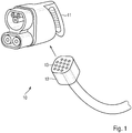
- FIG. 1 illustrates the addition of a charging cable (10) according to the invention to an additional connector (12), through which the contact pins subject to high wear and the shell can be formed as an exchangeable wear part.
- the contact pins or openings (13) of the proposed connector (12) can be designed for very few mating cycles.
- the actual charging plug plugged on as insulating body (11) can be manufactured with regard to its expected wear using cheaper pins and cheaper plastic.
- the charging cable (10) also has either its own interlock loop - for example in the form of a shorting bar - or is traversed by the interlock loop of a parent charging system.
- the outer region of the coupling immersed at least over a certain distance in the insulating body (11), which depends on the tracking resistance of the insulating material used.
- FIG. 2 and 3 illuminate the collar (14) countersunk for this purpose in detail, which at the same time prevents the pins from being touched when the connector (12) is slightly open, before the current flow through the interlock loop is reliably interrupted.
- the optional lock (15) which is effected in this case by the latch of a lock.
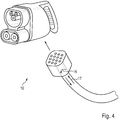
- FIGS. 4 and 5 draw the observer's attention to two optional variants of possible cable cooling of the connecting line (19).
- FIG. 3 This ends preferably, as in FIG. 4 shown, in the connector (12), for this purpose, only a connection (16) of inlet and outlet (17) establishes.
- the cooling of the connecting line (19) allows this to reduce their cable weight by reducing the cross section, while the cables in the insulating body (11) should have a significantly higher, ideally the standard values for the case of pure air convection corresponding conductor cross section.
- Any air pockets can be reliably removed by the service technician, for example by venting the cooling system.
Landscapes
- Engineering & Computer Science (AREA)
- Power Engineering (AREA)
- Transportation (AREA)
- Mechanical Engineering (AREA)
- Microelectronics & Electronic Packaging (AREA)
- Electric Propulsion And Braking For Vehicles (AREA)
Abstract
Description
- Die vorliegende Erfindung betrifft ein Ladekabel für Elektroautos. Die vorliegende Erfindung betrifft darüber hinaus eine entsprechende Ladestation.
- Als Ladestation wird in der Elektrotechnik jedwede stationäre Vorrichtung oder elektrische Anlage bezeichnet, welche dazu dient, mobilen akkubetriebenen Geräten, Maschinen oder Kraftfahrzeugen durch einfaches Einstellen oder Einstecken Energie zuzuführen, ohne den Energiespeicher - etwa die Traktionsbatterie eines Elektroautos - entnehmen zu müssen. Ladestationen für Elektroautos werden mitunter auch als "Stromtankstellen" bezeichnet und können mehrere Ladepunkte umfassen.
- Bekannt sind hier insbesondere Gleichstrom-Schnellladesysteme (high performance charging, HPC) wie das in Europa verbreitete sogenannte kombinierte Ladesystem (combined charging system, CCS). Beim gattungsmäßigen Gleichstromladen wird Gleichstrom aus der Ladesäule direkt in das Fahrzeug eingespeist und hierzu durch einen leistungsstarken Gleichrichter vom Stromnetz oder durch große Pufferakkumulatoren an Solartankstellen bereitgestellt. Im Fahrzeug befindet sich ein Batteriemanagementsystem, das mit der Ladesäule kommuniziert, um die Stromstärke anzupassen oder bei Erreichung einer Kapazitätsgrenze den Vorgang zu beenden.
- Die Leistungselektronik befindet sich hierbei üblicherweise in der Ladesäule. Da die Gleichstromanschlüsse der Ladesäule direkt mit entsprechenden Anschlüssen der Traktionsbatterie verbunden werden, lassen sich verlustarm hohe Ladeströme übertragen, was kurze Ladezeiten ermöglicht, aber auch eine beträchtliche Abwärme erzeugt.
- Für diesen Zweck sind unterschiedlichste Ladekabel sowie Ladekupplungen und -stecker bekannt, die typischerweise einem hohen Verschleiß ausgesetzt sind. Insbesondere die Kontaktstifte ("Pins") sind durch die hohe Anzahl von Steckzyklen im täglichen Gebrauch einem hohen Abrieb unterworfen. Die Abnutzung der Pins gefährdet jedoch den verlässlichen Kontakt insbesondere bei der Leitung von Signalen, die mit geringer Spannung übertragen werden. Die Kunststoffschale und die Pin-Halterung sind neben der mechanischen Abnutzung durch die häufigen Steckzyklen und die Kräfte auf die Pin-Fassungen auch der Zersetzung durch Witterung, Licht, Sauerstoff und andere Oxidationsmittel ausgesetzt. Dabei ist zu beachten, dass diese Bauteile eine sicherheitskritische Isolationsfunktion erfüllen. Dabei sind sie mitunter einer beträchtlichen mechanischen Belastung ausgesetzt, insbesondere durch ein Fallenlassen des Steckers auf den Boden. Das Kabel als relativ flexibles Element erträgt dies deutlich leichter als der Stecker.
- Ein vollständiger Ersatz des Steckers in regelmäßigen Zyklen ist daher branchenüblich, allerdings sehr kosten- und zeitintensiv. Wird der Stecker mit dem Kabel ausgetauscht, müssen die Ladesäulen in der Regel geöffnet werden, um alle Signal- und Leistungsleiter neu anzuschließen und die Kabelführung, etwaige Zugentlastungen oder Aufhängungen neu einzurichten. Werden dagegen nur der Stecker und die verschlissenen Pins ausgetauscht, so müssen in der Regel die Leitungsenden gekürzt und die neuen Pins gelötet oder gecrimpt werden. Vor Ort erweisen sich diese Verfahren als aufwändig und anfällig für Qualitätsprobleme. Ferner verringern sich mit jedem Austausch von Pins ungewollt die Kabellängen. Nach dem selektiven Austausch einzelner Pins haben die Leitungen zudem unterschiedliche Leitungslängen.
- Aufgrund des hohen Aufwandes beim Austausch von Ladekabeln im Feld werden daher teils kostenintensive widerstandsfähige Materialien verwendet, beispielsweise Gold-Nickel-Pins und zersetzungsbeständige Kunststoffe für die Stecker-Gehäuse, die jedoch den Austausch nur verzögern, nicht aber verhindern können.
-
CN105896212 ,DE102011106335 ,DE102013007330 ,EP2555340B1 sowieUS2015035483 offenbaren Elektrofahrzeug-Ladestecker mit austauschbaren Abschnitten. - Die Erfindung stellt ein Ladekabel für Elektroautos sowie eine entsprechende Ladestation gemäß den unabhängigen Ansprüchen bereit.
- Eine Grundidee der Erfindung besteht in der Teilung des Ladesteckers in mindestens einen Teil mit hohem Verschleiß und/oder hoher Sicherheitsfunktion oder -bedeutung sowie mindestens einen Teil mit geringerem Verschleiß und/oder niedrigerer Sicherheitsfunktion oder -bedeutung. Der Teil des Ladesteckers mit hohem Verschleiß und/oder hoher Sicherheitsfunktion oder -bedeutung wird entsprechend austauschbar gestaltet.
- Beispielsweise ist im Sinne der Erfindung der überwiegende Teil des Steckers, der in die mechanische Aufnahme im Fahrzeug eingeführt und damit mechanischem Abrieb und Belastung ausgesetzt wird, austauschbar. Es ist dabei vorteilhaft, dass möglichst alle sensitiven Teile (ggf. auch leicht brechende Teile des Gehäuses) Teil des Tauschteiles sind, andererseits aber so wenig wie möglich getauscht wird, um die Kosten des Teiles zu beschränken. Der Stecker- oder Isolationskörper kann insbesondere Pins enthalten, die ebenso mit dem Isolationskörper ausgetauscht werden. Wird der Isolationskörper wie eine Maske über den Stecker aufgesetzt, können - angesichts der häufigen Steckvorgänge mit wechselnden Fahrzeugen besonders verschleißanfälligen - Pins über hochwertige Kontaktstifte mit nur wenigen Steckzyklen mit dem Stecker verbunden werden. Diese zusätzlichen Pins benötigen hierbei nur sehr wenige Steckzyklen, da diese nur beim Wechsel des Isolationskörpers gesteckt werden.
- Weitere vorteilhafte Ausgestaltungen der Erfindung sind in den abhängigen Patentansprüchen angegeben. So können der Isolationskörper und mindestens ein Pin auf den Stecker-Körper aufsteckbar gestaltet werden. In diesem Fall sollte der Isolationskörper vorzugsweise am Stecker fixiert werden, beispielsweise mittels Schrauben, Klemmfedern oder Nieten. Vorzugsweise ist die Fixierung für Dritte nicht lösbar, beispielsweise durch die Verwendung von unüblichen Schraubenköpfen, Nieten, einer chemisch lösbaren Verklebung der Schrauben oder eines Schlosses.
- Ausführungsbeispiele der Erfindung sind in den Zeichnungen dargestellt und werden im Folgenden näher beschrieben.
-
Figur 1 zeigt das Beispiel eines erfindungsgemäßen CCS-Ladekabels gemäß EN 62196 Typ 2 ("IEC Typ 2") mit gelöstem Steckverbinder. -
Figur 2 zeigt die Kupplung des Steckverbinders in ihren Einzelheiten gemäß einer ersten Ausführungsform der Erfindung. -
Figur 3 zeigt die Kupplung des Steckverbinders in ihren Einzelheiten gemäß einer zweiten Ausführungsform der Erfindung. -
Figur 4 zeigt eine erste Ausführungsvariante des CCS-Ladekabels. -
Figur 5 zeigt eine zweite Ausführungsvariante des CCS-Ladekabels. -
Figur 1 illustriert die erfindungsgemäße Ergänzung eines Ladekabels (10) um einen zusätzlichen Steckverbinder (12), durch welchen die einer hoher Abnutzung unterworfenen Kontaktstifte und die Schale gleichsam als austauschbares Verschleißteil ausgebildet werden können. Die Kontaktstifte oder -Öffnungen (13) des vorgeschlagenen Steckverbinders (12) können hierbei für sehr wenige Steckzyklen ausgelegt sein. Der als Isolationskörper (11) aufgesteckte eigentliche Ladestecker hingegen kann im Hinblick auf seinen erwarteten Verschleiß unter Verwendung günstigerer Pins und günstigeren Kunststoffs gefertigt werden. - Um ein Trennen des Steckverbinders (12) durch Unbefugte zu verhindern, sind beispielsweise nicht mit Standardwerkzeug lösbare Sicherheitsschrauben oder ein Schloss vorgesehen. Zur Erkennung eines Absteckens und Abbrechen des Ladevorganges durch Abschalten der Spannung verfügt das Ladekabel (10) zudem entweder über eine eigene Interlockschleife - beispielsweise in Gestalt eines Kurzschlussbügels - oder wird von der Interlockschleife eines übergeordneten Ladesystems durchzogen. Vorzugsweise taucht der Außenbereich der Kupplung zumindest über eine gewisse Strecke in den Isolationskörper (11) ein, die von der Kriechstromfestigkeit des verwendeten Isolierstoffes abhängt.
-
Figur 2 und3 beleuchten den zu diesem Zweck versenkten Kragen (14) im Detail, welcher zugleich verhindert, dass bei leicht geöffnetem Steckverbinder (12) die Pins berührbar sind, bevor der Stromfluss durch die Interlockschleife sicher unterbrochen wird. Erkennbar ist in dieser Abbildung zudem die optionale Verriegelung (15), die vorliegend durch den Riegel eines Schlosses bewirkt wird. - Die
Figuren 4 und5 lenken das Augenmerk des Betrachters auf zwei optionale Ausführungsvarianten einer etwaigen Kabelkühlung der Anschlussleitung (19 -Figur 3 ). Diese endet vorzugsweise, wie inFigur 4 dargestellt, im Steckverbinder (12), der zu diesem Zweck lediglich eine Verbindung (16) von Zu- und Ablauf (17) herstellt. Somit werden, wenn keine Übergabe des Kühlmediums an das Fahrzeug vorgesehen ist, die Kosten für Flüssigkeitskupplungen gespart. Die Kühlung der Anschlussleitung (19) erlaubt es hierbei, deren Kabelgewicht durch eine Querschnittsreduzierung zu verringern, während die Kabel im Isolationskörper (11) einen deutlich höheren, idealerweise den Normwerten für den Fall einer reinen Luftkonvektion entsprechenden Leiterquerschnitt aufweisen sollten. - Sollte trotzdem das Kühlmedium bis in den Isolationskörper (11) transportiert werden, so bietet die Lösung gemäß
Figur 5 den Vorteil, dass kostengünstige nicht Leckage-freie oder sogar nicht absperrende Flüssigkeitskupplungen (18) verwendet werden können. - Etwaige Lufteinschlüsse können vom Servicetechniker zuverlässig beispielsweise durch eine Entlüftung des Kühlsystems beseitigt werden.
Claims (12)
- Ladekabel (10) für ein Elektroauto,
gekennzeichnet durch folgende Merkmale:- das Ladekabel (10) umfasst einen Isolationskörper (11), einen Steckverbinder (12) mit Kontaktstiften und Kontaktöffnungen (13) sowie eine Anschlussleitung (19) und- der Steckverbinder (12) verbindet den Isolationskörper (11) über die Kontaktstifte und Kontaktöffnungen (13) lösbar mit der Anschlussleitung (19). - Ladekabel (10) nach Anspruch 1,
gekennzeichnet durch eines der folgenden Merkmale:- die Kontaktstifte sind dauerhaft mit dem Isolationskörper (11) verbunden oder- die Kontaktstifte sind dauerhaft mit der Anschlussleitung (19) verbunden. - Ladekabel (10) nach Anspruch 1 oder 2,
gekennzeichnet durch folgende Merkmale:- der Steckverbinder (12) weist einen Kragen (14) auf und- der Steckverbinder (12) ist derart geformt, dass der Kragen (14) in den Steckverbinder (12) eintaucht, wenn der Isolationskörper (11) mit der Anschlussleitung (19) verbunden wird. - Ladekabel (10) nach Anspruch 3,
gekennzeichnet durch folgendes Merkmal:- der Kragen (14) weist eine mechanische Verriegelung (15), insbesondere ein Schloss auf. - Ladekabel (10) nach einem der Ansprüche 1 bis 4,
gekennzeichnet durch folgendes Merkmal:- das Ladekabel (10) weist eine Interlockschleife, insbesondere einen Kurzschlussbügel auf. - Ladekabel (10) nach einem der Ansprüche 1 bis 5,
gekennzeichnet durch mindestens eines der folgenden Merkmale:- der Steckverbinder (12) weist Schrauben, insbesondere Sicherheitsschrauben, auf,- der Steckverbinder (12) weist Klemmfedern auf oder- der Steckverbinder (12) weist Niete auf. - Ladekabel (10) nach einem der Ansprüche 1 bis 6,
gekennzeichnet durch folgendes Merkmal:- die Anschlussleitung (19) weist einen Zu- und Ablauf (17) für Kühlflüssigkeit auf. - Ladekabel (10) nach Anspruch 7,
gekennzeichnet durch folgendes Merkmal:- der Steckverbinder (12) umfasst eine fluidtechnische Verbindung (16) des Zu- und Ablaufes (17). - Ladekabel (10) nach Anspruch 7,
gekennzeichnet durch folgende Merkmale:- der Steckverbinder (12) weist Flüssigkeitskupplungen (18) des Zu- und Ablaufes (17) an den Isolationskörper (11) auf und- der Isolationskörper (11) ist für eine Kühlung mittels der Kühlflüssigkeit eingerichtet. - Ladekabel (10) nach einem der Ansprüche 1 bis 9,
gekennzeichnet durch folgende Merkmale:- der Isolationskörper (11) umfasst mindestens einen Kontaktstift oder mindestens eine Kontaktöffnung mit einer um mindestens 30 % höheren Anzahl von spezifizierten maximalen Steckzyklen über der Lebensdauer als zumindest ein Kontaktstift oder eine Kontaktöffnung im Steckverbinder (12). - Ladekabel (10) nach Anspruch 10,
gekennzeichnet durch folgende Merkmale:- der mindestens eine Kontaktstift oder die mindestens eine Kontaktöffnung des Isolationskörpers (11) verfügt über eine Nickel-Gold-Oberfläche. - Ladestation mit einem Ladekabel (10) nach einem der Ansprüche 1 bis 11.
Applications Claiming Priority (1)
| Application Number | Priority Date | Filing Date | Title |
|---|---|---|---|
| DE102018100827.9A DE102018100827A1 (de) | 2018-01-16 | 2018-01-16 | Ladekabel und Ladestation für Elektroautos |
Publications (2)
| Publication Number | Publication Date |
|---|---|
| EP3512046A1 true EP3512046A1 (de) | 2019-07-17 |
| EP3512046B1 EP3512046B1 (de) | 2020-09-02 |
Family
ID=63965050
Family Applications (1)
| Application Number | Title | Priority Date | Filing Date |
|---|---|---|---|
| EP18020550.2A Active EP3512046B1 (de) | 2018-01-16 | 2018-10-24 | Ladekabel und ladestation für elektroautos |
Country Status (4)
| Country | Link |
|---|---|
| US (1) | US11180043B2 (de) |
| EP (1) | EP3512046B1 (de) |
| CN (1) | CN110048284A (de) |
| DE (1) | DE102018100827A1 (de) |
Cited By (1)
| Publication number | Priority date | Publication date | Assignee | Title |
|---|---|---|---|---|
| US20230047203A1 (en) * | 2021-08-13 | 2023-02-16 | Abb Schweiz Ag | Electric Vehicle Charging System |
Families Citing this family (16)
| Publication number | Priority date | Publication date | Assignee | Title |
|---|---|---|---|---|
| DE102017115224A1 (de) * | 2017-07-07 | 2019-01-10 | Paxos Consulting & Engineering GmbH & Co. KG | Ladestecker und Ladestecker-Ladebuchsen-System zum Laden eines Elektrofahrzeugs |
| CH715611B1 (de) * | 2018-12-05 | 2022-05-13 | BRUGG eConnect AG | Anschlusselement zum elektrischen Anschliessen einer fluidkühlbaren Einzelleitung, fluidkühlbare Einzelleitungseinheit und Ladekabel. |
| DE102019202886B4 (de) * | 2019-03-04 | 2025-07-03 | Volkswagen Aktiengesellschaft | Ladekabel, Ladestecker, Ladestation und Ladeanordnung zum Laden eines Elektrofahrzeuges und Verfahren zum Ausbilden einer elektrischen Verbindung zwischen einer Ladestation und einem Elektrofahrzeug |
| NL2023045B1 (en) * | 2019-05-01 | 2020-12-02 | Prysmian Spa | Cable assembly |
| KR102674661B1 (ko) * | 2019-07-11 | 2024-06-13 | 현대자동차주식회사 | 차량용 배터리의 열관리 시스템 및 이를 제어하는 방법 |
| EP3771045A1 (de) * | 2019-07-25 | 2021-01-27 | ABB Schweiz AG | Ladeanordnung zum laden von elektrischen fahrzeugen |
| US11303073B2 (en) * | 2020-09-17 | 2022-04-12 | TE Connectivity Services Gmbh | Charging inlet assembly |
| US20220089046A1 (en) * | 2020-09-21 | 2022-03-24 | Phihong Technology Co., Ltd. | Electric Vehicle Charger with Interchangable AC Power Plug |
| US12107373B2 (en) * | 2021-07-15 | 2024-10-01 | Japan Aviation Electronics Industry, Limited | Assembly including a cable and a connector with second coupling portion of each DC contact of connector coupled with first coupling portions of at least two DC wires of cable |
| US11712976B2 (en) * | 2021-07-16 | 2023-08-01 | Toyota Motor Engineering & Manufacturing North America, Inc. | Hybrid electric vehicle battery lockout plug |
| DE102022101420A1 (de) | 2022-01-21 | 2023-07-27 | Man Truck & Bus Se | Steckverbinder zum Verbinden von Hochvoltkomponenten |
| DE102022202231B4 (de) | 2022-03-04 | 2025-06-12 | Robert Bosch Gesellschaft mit beschränkter Haftung | Verbinder für ein Versorgungskabel und Versorgungskabel für ein Fahrzeug |
| US11973288B1 (en) * | 2023-03-15 | 2024-04-30 | Beta Air, Llc | Apparatus for a locking thermal conditioning hose for an electric aircraft and method of use |
| USD1087030S1 (en) * | 2023-11-30 | 2025-08-05 | Dongguan LanXin Charging Technology Co., Ltd. | Adapter |
| CN222422680U (zh) * | 2024-03-08 | 2025-01-28 | 风格派(深圳)创新科技有限公司 | 一种户外多功能数据线 |
| DE102024107819A1 (de) * | 2024-03-19 | 2025-09-25 | BRUGG eConnect AG | Kupplungsvorrichtung, Ladestecker-System, Ladevorrichtung, Baukasten zur Herstellung unterschiedlicher Ladestecker-Systeme, Ladestation und Verfahren |
Citations (4)
| Publication number | Priority date | Publication date | Assignee | Title |
|---|---|---|---|---|
| US3271725A (en) * | 1963-09-30 | 1966-09-06 | Boeing Co | Electrical connector |
| JP2016509824A (ja) * | 2013-12-06 | 2016-03-31 | リ,ジン−クク | 電気車用充電装置 |
| US20170001529A1 (en) * | 2014-01-31 | 2017-01-05 | Siemens Aktiengesellschaft | Electrical connecting device and charging cable for an electric vehicle |
| DE102015112347A1 (de) * | 2015-07-29 | 2017-02-02 | Dr. Ing. H.C. F. Porsche Aktiengesellschaft | Ladestation mit einem Ladekabel |
Family Cites Families (29)
| Publication number | Priority date | Publication date | Assignee | Title |
|---|---|---|---|---|
| JP3028704B2 (ja) * | 1993-05-10 | 2000-04-04 | 住友電装株式会社 | 電気自動車充電用コネクタ |
| US6220955B1 (en) * | 1998-02-17 | 2001-04-24 | John G. Posa | Combination power and cooling cable |
| US6371768B1 (en) * | 1998-03-31 | 2002-04-16 | Daimlerchrysler Corporation | Universal charge port connector for electric vehicles |
| US6231358B1 (en) * | 2000-01-06 | 2001-05-15 | Angelo Fan Brace Licensing, L.L.C. | Electrical plug and receptacle having safety features |
| US6358096B1 (en) * | 2000-12-29 | 2002-03-19 | Gateway, Inc. | Multiple source power adapter for output power control |
| SE0203249L (sv) * | 2002-11-05 | 2004-02-03 | Volvo Lastvagnar Ab | Kabelkanal för ett fordon samt metod för att montera ett kablage på ett fordon |
| US7070417B2 (en) * | 2004-09-28 | 2006-07-04 | Phillips & Temro Industries Inc. | Breakable connector for connecting a vehicle to a power source |
| CN101740947B (zh) * | 2008-11-25 | 2012-08-01 | 比亚迪股份有限公司 | 用于可电力驱动的车辆的充电装置 |
| US9168822B2 (en) * | 2009-05-28 | 2015-10-27 | Toyota Jidosha Kabushiki Kaisha | Charging system |
| DE102010041314B4 (de) * | 2010-09-24 | 2021-09-09 | Kiekert Aktiengesellschaft | Ladeeinrichtung für ein Elektrofahrzeug nebst Verfahren |
| DE102011106335B4 (de) | 2011-07-01 | 2017-05-24 | Volkswagen Aktiengesellschaft | Vorrichtung und Verfahren zum elektrischen Laden eines Elektrofahrzeuges an einer Ladestation |
| FR2978877B1 (fr) | 2011-08-03 | 2014-02-28 | Renault Sas | Fiche de raccordement electrique modulable, element electrique pour une telle fiche, set d'elements electriques et vehicule electrique comportant une telle fiche |
| JP5758746B2 (ja) * | 2011-08-30 | 2015-08-05 | トヨタ自動車株式会社 | 給電コネクタ、車両および車両の制御方法 |
| US9080246B2 (en) * | 2012-10-12 | 2015-07-14 | Galvanotech | Selective plating apparatus and method |
| DE102013007330B4 (de) | 2013-04-27 | 2019-11-28 | Volkswagen Aktiengesellschaft | Teilesatz mit Wechselstecker zum länderübergreifenden elektrischen Laden eines Fortbewegungsmittels |
| US10046658B2 (en) | 2013-08-01 | 2018-08-14 | Lear Corporation | Electrical cable assembly for electric vehicle |
| US9321362B2 (en) * | 2014-02-05 | 2016-04-26 | Tesia Motors, Inc. | Cooling of charging cable |
| CN204597152U (zh) * | 2015-06-03 | 2015-08-26 | 重庆凯瑞电动汽车系统有限公司 | 一种带有电量显示功能的电动汽车充电枪 |
| CN204597169U (zh) * | 2015-06-03 | 2015-08-26 | 重庆凯瑞电动汽车系统有限公司 | 一种多功能电动汽车充电枪 |
| KR101793717B1 (ko) * | 2015-08-07 | 2017-11-03 | 조인셋 주식회사 | 전기접속단자 |
| DE102015117508A1 (de) * | 2015-10-15 | 2017-04-20 | Phoenix Contact E-Mobility Gmbh | Elektrisches Kabel mit einer Fluidleitung zum Kühlen |
| DE102016105311A1 (de) * | 2016-03-22 | 2017-09-28 | Phoenix Contact E-Mobility Gmbh | Steckverbinderteil mit einem gekühlten Kontaktelement |
| DE102016204895B4 (de) * | 2016-03-23 | 2020-11-12 | Phoenix Contact E-Mobility Gmbh | Ladestecker mit einem Leistungskontaktsystem und Ladestation zur Abgabe elektrischer Energie an einen Empfänger elektrischer Energie |
| DE102016003652A1 (de) * | 2016-03-30 | 2017-10-05 | Conti Temic Microelectronic Gmbh | Steckverbinder für ein Kraftfahrzeug und Vorrichtung eines Kraftfahrzeugs mit einem Steckberbinder |
| DE102016107409A1 (de) * | 2016-04-21 | 2017-10-26 | Phoenix Contact E-Mobility Gmbh | Steckverbinderteil mit einem gekühlten Kontaktelement |
| CN205791669U (zh) * | 2016-05-28 | 2016-12-07 | 安徽易威斯新能源科技股份有限公司 | 一种便于更换充电枪的充电桩 |
| CN105896212A (zh) | 2016-05-31 | 2016-08-24 | 深圳巴斯巴科技发展有限公司 | 一种新型可转换插针的电动车连接器插头 |
| DE102016210721A1 (de) * | 2016-06-16 | 2017-12-21 | Bayerische Motoren Werke Aktiengesellschaft | HV-Interlock Stecksystem mit Temperatursensor |
| CN206820162U (zh) * | 2017-06-02 | 2017-12-29 | 云杉智慧新能源技术有限公司 | 一种电动汽车充电枪及充电线缆 |
-
2018
- 2018-01-16 DE DE102018100827.9A patent/DE102018100827A1/de not_active Ceased
- 2018-10-24 EP EP18020550.2A patent/EP3512046B1/de active Active
-
2019
- 2019-01-11 US US16/245,478 patent/US11180043B2/en active Active
- 2019-01-11 CN CN201910026529.3A patent/CN110048284A/zh active Pending
Patent Citations (4)
| Publication number | Priority date | Publication date | Assignee | Title |
|---|---|---|---|---|
| US3271725A (en) * | 1963-09-30 | 1966-09-06 | Boeing Co | Electrical connector |
| JP2016509824A (ja) * | 2013-12-06 | 2016-03-31 | リ,ジン−クク | 電気車用充電装置 |
| US20170001529A1 (en) * | 2014-01-31 | 2017-01-05 | Siemens Aktiengesellschaft | Electrical connecting device and charging cable for an electric vehicle |
| DE102015112347A1 (de) * | 2015-07-29 | 2017-02-02 | Dr. Ing. H.C. F. Porsche Aktiengesellschaft | Ladestation mit einem Ladekabel |
Cited By (2)
| Publication number | Priority date | Publication date | Assignee | Title |
|---|---|---|---|---|
| US20230047203A1 (en) * | 2021-08-13 | 2023-02-16 | Abb Schweiz Ag | Electric Vehicle Charging System |
| US12583346B2 (en) * | 2021-08-13 | 2026-03-24 | Abb Schweiz Ag | Electric vehicle charging system |
Also Published As
| Publication number | Publication date |
|---|---|
| DE102018100827A1 (de) | 2019-07-18 |
| EP3512046B1 (de) | 2020-09-02 |
| US11180043B2 (en) | 2021-11-23 |
| CN110048284A (zh) | 2019-07-23 |
| US20190217731A1 (en) | 2019-07-18 |
Similar Documents
| Publication | Publication Date | Title |
|---|---|---|
| EP3512046B1 (de) | Ladekabel und ladestation für elektroautos | |
| EP3512053B1 (de) | Ladestecker für elektroautos und dessen herstellung | |
| EP3446369B1 (de) | Leistungskontakt mit auswechselbarem kontaktbereich | |
| DE102012100235B4 (de) | Kabelstecker mit Abdeckeinrichtung | |
| DE202008013600U1 (de) | Vorrichtung zur Herstellung einer Verbindung | |
| EP2466697A1 (de) | Datenkabelanschlussmodul sowie ein Verfahren zu dessen Konfektion an einem Kabel | |
| WO2021027991A1 (de) | Hybridsteckverbinder | |
| DE102008052857A1 (de) | Vorrichtung für eine Netzwerkverbindung | |
| EP3391476B1 (de) | Mechanische sicherung einer elektrischen steckverbindung für netzspannungen | |
| DE19613793C2 (de) | Mehrpolige Steckvorrichtung nach DIN EN 60309/IEC 60309 | |
| DE102022106384A1 (de) | Verbinder und Verbinderbaugruppe | |
| DE102008030337A1 (de) | Hochvolt-Steckverbindung, insbesondere für Kraftfahrzeuge | |
| WO2014095205A2 (de) | Steckverbindung für schienengebundene fahrzeuge | |
| EP4216366A1 (de) | Datenleitung für ein fahrzeug | |
| DE102022106380A1 (de) | Verbinder und Verbinderbaugruppe | |
| DE102021123620A1 (de) | Elektrische Steckervorrichtung, Kontakteinrichtung dafür sowie Verfahren zur Herstellung | |
| DE102022132133B3 (de) | Wechseleinsatz für eine ladedose und ladedose | |
| DE102021110913A1 (de) | Ladesteckereinrichtung, Ladekabel und Verfahren zum Bereitstellen einer Ladesteckereinrichtung | |
| DE102018108429A1 (de) | Steckereinheit für ein elektrisch antreibbares Fahrzeug, elektrisch antreibbares Fahrzeug, Akkumulatorpaket, Ladegerät und Abdeckkappe | |
| DE19751668A1 (de) | Steckverbindung zum Übertragen von Daten zwischen einer elektrischen Spannungsquelle und einer Datenverarbeitungseinrichtung | |
| DE202019000733U1 (de) | Mehrfachanschluss für unterschiedliche Verbindungssysteme | |
| DE102018208672A1 (de) | Ladestecker | |
| DE102023116755A1 (de) | Set zur Herstellung eines Ladesteckverbinders für Elektro- und Hybridfahrzeuge | |
| WO2009013080A2 (de) | Elektrische steckverbindung | |
| DE102024120376A1 (de) | System aus Ladekontakt und elektrischer Leitung für Elektro- und Hybridfahrzeuge |
Legal Events
| Date | Code | Title | Description |
|---|---|---|---|
| PUAI | Public reference made under article 153(3) epc to a published international application that has entered the european phase |
Free format text: ORIGINAL CODE: 0009012 |
|
| STAA | Information on the status of an ep patent application or granted ep patent |
Free format text: STATUS: THE APPLICATION HAS BEEN PUBLISHED |
|
| AK | Designated contracting states |
Kind code of ref document: A1 Designated state(s): AL AT BE BG CH CY CZ DE DK EE ES FI FR GB GR HR HU IE IS IT LI LT LU LV MC MK MT NL NO PL PT RO RS SE SI SK SM TR |
|
| AX | Request for extension of the european patent |
Extension state: BA ME |
|
| STAA | Information on the status of an ep patent application or granted ep patent |
Free format text: STATUS: REQUEST FOR EXAMINATION WAS MADE |
|
| STAA | Information on the status of an ep patent application or granted ep patent |
Free format text: STATUS: EXAMINATION IS IN PROGRESS |
|
| 17P | Request for examination filed |
Effective date: 20200117 |
|
| RBV | Designated contracting states (corrected) |
Designated state(s): AL AT BE BG CH CY CZ DE DK EE ES FI FR GB GR HR HU IE IS IT LI LT LU LV MC MK MT NL NO PL PT RO RS SE SI SK SM TR |
|
| 17Q | First examination report despatched |
Effective date: 20200206 |
|
| GRAP | Despatch of communication of intention to grant a patent |
Free format text: ORIGINAL CODE: EPIDOSNIGR1 |
|
| STAA | Information on the status of an ep patent application or granted ep patent |
Free format text: STATUS: GRANT OF PATENT IS INTENDED |
|
| INTG | Intention to grant announced |
Effective date: 20200403 |
|
| RAP1 | Party data changed (applicant data changed or rights of an application transferred) |
Owner name: DR.ING. H.C. F. PORSCHE AKTIENGESELLSCHAFT |
|
| GRAS | Grant fee paid |
Free format text: ORIGINAL CODE: EPIDOSNIGR3 |
|
| GRAA | (expected) grant |
Free format text: ORIGINAL CODE: 0009210 |
|
| STAA | Information on the status of an ep patent application or granted ep patent |
Free format text: STATUS: THE PATENT HAS BEEN GRANTED |
|
| AK | Designated contracting states |
Kind code of ref document: B1 Designated state(s): AL AT BE BG CH CY CZ DE DK EE ES FI FR GB GR HR HU IE IS IT LI LT LU LV MC MK MT NL NO PL PT RO RS SE SI SK SM TR |
|
| REG | Reference to a national code |
Ref country code: GB Ref legal event code: FG4D Free format text: NOT ENGLISH |
|
| REG | Reference to a national code |
Ref country code: AT Ref legal event code: REF Ref document number: 1309890 Country of ref document: AT Kind code of ref document: T Effective date: 20200915 Ref country code: CH Ref legal event code: EP |
|
| REG | Reference to a national code |
Ref country code: DE Ref legal event code: R096 Ref document number: 502018002302 Country of ref document: DE |
|
| REG | Reference to a national code |
Ref country code: IE Ref legal event code: FG4D Free format text: LANGUAGE OF EP DOCUMENT: GERMAN |
|
| REG | Reference to a national code |
Ref country code: LT Ref legal event code: MG4D |
|
| PG25 | Lapsed in a contracting state [announced via postgrant information from national office to epo] |
Ref country code: LT Free format text: LAPSE BECAUSE OF FAILURE TO SUBMIT A TRANSLATION OF THE DESCRIPTION OR TO PAY THE FEE WITHIN THE PRESCRIBED TIME-LIMIT Effective date: 20200902 Ref country code: FI Free format text: LAPSE BECAUSE OF FAILURE TO SUBMIT A TRANSLATION OF THE DESCRIPTION OR TO PAY THE FEE WITHIN THE PRESCRIBED TIME-LIMIT Effective date: 20200902 Ref country code: BG Free format text: LAPSE BECAUSE OF FAILURE TO SUBMIT A TRANSLATION OF THE DESCRIPTION OR TO PAY THE FEE WITHIN THE PRESCRIBED TIME-LIMIT Effective date: 20201202 Ref country code: NO Free format text: LAPSE BECAUSE OF FAILURE TO SUBMIT A TRANSLATION OF THE DESCRIPTION OR TO PAY THE FEE WITHIN THE PRESCRIBED TIME-LIMIT Effective date: 20201202 Ref country code: GR Free format text: LAPSE BECAUSE OF FAILURE TO SUBMIT A TRANSLATION OF THE DESCRIPTION OR TO PAY THE FEE WITHIN THE PRESCRIBED TIME-LIMIT Effective date: 20201203 Ref country code: SE Free format text: LAPSE BECAUSE OF FAILURE TO SUBMIT A TRANSLATION OF THE DESCRIPTION OR TO PAY THE FEE WITHIN THE PRESCRIBED TIME-LIMIT Effective date: 20200902 Ref country code: HR Free format text: LAPSE BECAUSE OF FAILURE TO SUBMIT A TRANSLATION OF THE DESCRIPTION OR TO PAY THE FEE WITHIN THE PRESCRIBED TIME-LIMIT Effective date: 20200902 |
|
| REG | Reference to a national code |
Ref country code: NL Ref legal event code: MP Effective date: 20200902 |
|
| PG25 | Lapsed in a contracting state [announced via postgrant information from national office to epo] |
Ref country code: RS Free format text: LAPSE BECAUSE OF FAILURE TO SUBMIT A TRANSLATION OF THE DESCRIPTION OR TO PAY THE FEE WITHIN THE PRESCRIBED TIME-LIMIT Effective date: 20200902 Ref country code: PL Free format text: LAPSE BECAUSE OF FAILURE TO SUBMIT A TRANSLATION OF THE DESCRIPTION OR TO PAY THE FEE WITHIN THE PRESCRIBED TIME-LIMIT Effective date: 20200902 Ref country code: LV Free format text: LAPSE BECAUSE OF FAILURE TO SUBMIT A TRANSLATION OF THE DESCRIPTION OR TO PAY THE FEE WITHIN THE PRESCRIBED TIME-LIMIT Effective date: 20200902 |
|
| PG25 | Lapsed in a contracting state [announced via postgrant information from national office to epo] |
Ref country code: SM Free format text: LAPSE BECAUSE OF FAILURE TO SUBMIT A TRANSLATION OF THE DESCRIPTION OR TO PAY THE FEE WITHIN THE PRESCRIBED TIME-LIMIT Effective date: 20200902 Ref country code: RO Free format text: LAPSE BECAUSE OF FAILURE TO SUBMIT A TRANSLATION OF THE DESCRIPTION OR TO PAY THE FEE WITHIN THE PRESCRIBED TIME-LIMIT Effective date: 20200902 Ref country code: PT Free format text: LAPSE BECAUSE OF FAILURE TO SUBMIT A TRANSLATION OF THE DESCRIPTION OR TO PAY THE FEE WITHIN THE PRESCRIBED TIME-LIMIT Effective date: 20210104 Ref country code: CZ Free format text: LAPSE BECAUSE OF FAILURE TO SUBMIT A TRANSLATION OF THE DESCRIPTION OR TO PAY THE FEE WITHIN THE PRESCRIBED TIME-LIMIT Effective date: 20200902 Ref country code: EE Free format text: LAPSE BECAUSE OF FAILURE TO SUBMIT A TRANSLATION OF THE DESCRIPTION OR TO PAY THE FEE WITHIN THE PRESCRIBED TIME-LIMIT Effective date: 20200902 |
|
| PG25 | Lapsed in a contracting state [announced via postgrant information from national office to epo] |
Ref country code: IS Free format text: LAPSE BECAUSE OF FAILURE TO SUBMIT A TRANSLATION OF THE DESCRIPTION OR TO PAY THE FEE WITHIN THE PRESCRIBED TIME-LIMIT Effective date: 20210102 Ref country code: AL Free format text: LAPSE BECAUSE OF FAILURE TO SUBMIT A TRANSLATION OF THE DESCRIPTION OR TO PAY THE FEE WITHIN THE PRESCRIBED TIME-LIMIT Effective date: 20200902 Ref country code: ES Free format text: LAPSE BECAUSE OF FAILURE TO SUBMIT A TRANSLATION OF THE DESCRIPTION OR TO PAY THE FEE WITHIN THE PRESCRIBED TIME-LIMIT Effective date: 20200902 |
|
| REG | Reference to a national code |
Ref country code: DE Ref legal event code: R097 Ref document number: 502018002302 Country of ref document: DE |
|
| PG25 | Lapsed in a contracting state [announced via postgrant information from national office to epo] |
Ref country code: MC Free format text: LAPSE BECAUSE OF FAILURE TO SUBMIT A TRANSLATION OF THE DESCRIPTION OR TO PAY THE FEE WITHIN THE PRESCRIBED TIME-LIMIT Effective date: 20200902 Ref country code: SK Free format text: LAPSE BECAUSE OF FAILURE TO SUBMIT A TRANSLATION OF THE DESCRIPTION OR TO PAY THE FEE WITHIN THE PRESCRIBED TIME-LIMIT Effective date: 20200902 Ref country code: LU Free format text: LAPSE BECAUSE OF NON-PAYMENT OF DUE FEES Effective date: 20201024 |
|
| PLBE | No opposition filed within time limit |
Free format text: ORIGINAL CODE: 0009261 |
|
| STAA | Information on the status of an ep patent application or granted ep patent |
Free format text: STATUS: NO OPPOSITION FILED WITHIN TIME LIMIT |
|
| REG | Reference to a national code |
Ref country code: BE Ref legal event code: MM Effective date: 20201031 |
|
| PG25 | Lapsed in a contracting state [announced via postgrant information from national office to epo] |
Ref country code: FR Free format text: LAPSE BECAUSE OF NON-PAYMENT OF DUE FEES Effective date: 20201102 |
|
| 26N | No opposition filed |
Effective date: 20210603 |
|
| PG25 | Lapsed in a contracting state [announced via postgrant information from national office to epo] |
Ref country code: BE Free format text: LAPSE BECAUSE OF NON-PAYMENT OF DUE FEES Effective date: 20201031 Ref country code: SI Free format text: LAPSE BECAUSE OF FAILURE TO SUBMIT A TRANSLATION OF THE DESCRIPTION OR TO PAY THE FEE WITHIN THE PRESCRIBED TIME-LIMIT Effective date: 20200902 Ref country code: DK Free format text: LAPSE BECAUSE OF FAILURE TO SUBMIT A TRANSLATION OF THE DESCRIPTION OR TO PAY THE FEE WITHIN THE PRESCRIBED TIME-LIMIT Effective date: 20200902 |
|
| PG25 | Lapsed in a contracting state [announced via postgrant information from national office to epo] |
Ref country code: IE Free format text: LAPSE BECAUSE OF NON-PAYMENT OF DUE FEES Effective date: 20201024 Ref country code: IT Free format text: LAPSE BECAUSE OF FAILURE TO SUBMIT A TRANSLATION OF THE DESCRIPTION OR TO PAY THE FEE WITHIN THE PRESCRIBED TIME-LIMIT Effective date: 20200902 |
|
| REG | Reference to a national code |
Ref country code: CH Ref legal event code: PL |
|
| PG25 | Lapsed in a contracting state [announced via postgrant information from national office to epo] |
Ref country code: TR Free format text: LAPSE BECAUSE OF FAILURE TO SUBMIT A TRANSLATION OF THE DESCRIPTION OR TO PAY THE FEE WITHIN THE PRESCRIBED TIME-LIMIT Effective date: 20200902 Ref country code: MT Free format text: LAPSE BECAUSE OF FAILURE TO SUBMIT A TRANSLATION OF THE DESCRIPTION OR TO PAY THE FEE WITHIN THE PRESCRIBED TIME-LIMIT Effective date: 20200902 Ref country code: CY Free format text: LAPSE BECAUSE OF FAILURE TO SUBMIT A TRANSLATION OF THE DESCRIPTION OR TO PAY THE FEE WITHIN THE PRESCRIBED TIME-LIMIT Effective date: 20200902 |
|
| PG25 | Lapsed in a contracting state [announced via postgrant information from national office to epo] |
Ref country code: MK Free format text: LAPSE BECAUSE OF FAILURE TO SUBMIT A TRANSLATION OF THE DESCRIPTION OR TO PAY THE FEE WITHIN THE PRESCRIBED TIME-LIMIT Effective date: 20200902 |
|
| PG25 | Lapsed in a contracting state [announced via postgrant information from national office to epo] |
Ref country code: LI Free format text: LAPSE BECAUSE OF NON-PAYMENT OF DUE FEES Effective date: 20211031 Ref country code: CH Free format text: LAPSE BECAUSE OF NON-PAYMENT OF DUE FEES Effective date: 20211031 |
|
| GBPC | Gb: european patent ceased through non-payment of renewal fee |
Effective date: 20221024 |
|
| PG25 | Lapsed in a contracting state [announced via postgrant information from national office to epo] |
Ref country code: NL Free format text: LAPSE BECAUSE OF NON-PAYMENT OF DUE FEES Effective date: 20200923 |
|
| P01 | Opt-out of the competence of the unified patent court (upc) registered |
Effective date: 20230526 |
|
| PG25 | Lapsed in a contracting state [announced via postgrant information from national office to epo] |
Ref country code: GB Free format text: LAPSE BECAUSE OF NON-PAYMENT OF DUE FEES Effective date: 20221024 |
|
| REG | Reference to a national code |
Ref country code: AT Ref legal event code: MM01 Ref document number: 1309890 Country of ref document: AT Kind code of ref document: T Effective date: 20231024 |
|
| PG25 | Lapsed in a contracting state [announced via postgrant information from national office to epo] |
Ref country code: AT Free format text: LAPSE BECAUSE OF NON-PAYMENT OF DUE FEES Effective date: 20231024 |
|
| PG25 | Lapsed in a contracting state [announced via postgrant information from national office to epo] |
Ref country code: AT Free format text: LAPSE BECAUSE OF NON-PAYMENT OF DUE FEES Effective date: 20231024 |
|
| PGFP | Annual fee paid to national office [announced via postgrant information from national office to epo] |
Ref country code: DE Payment date: 20251029 Year of fee payment: 8 |
|
| PGFP | Annual fee paid to national office [announced via postgrant information from national office to epo] |
Ref country code: AT Payment date: 20260410 Year of fee payment: 5 |