EP3510369B1 - Vacuum pump comprising infrared temperature sensing system - Google Patents
Vacuum pump comprising infrared temperature sensing system Download PDFInfo
- Publication number
- EP3510369B1 EP3510369B1 EP17767885.1A EP17767885A EP3510369B1 EP 3510369 B1 EP3510369 B1 EP 3510369B1 EP 17767885 A EP17767885 A EP 17767885A EP 3510369 B1 EP3510369 B1 EP 3510369B1
- Authority
- EP
- European Patent Office
- Prior art keywords
- infrared sensor
- vacuum pump
- motor
- temperature
- operational status
- Prior art date
- Legal status (The legal status is an assumption and is not a legal conclusion. Google has not performed a legal analysis and makes no representation as to the accuracy of the status listed.)
- Active
Links
Images

Classifications
-
- G—PHYSICS
- G01—MEASURING; TESTING
- G01J—MEASUREMENT OF INTENSITY, VELOCITY, SPECTRAL CONTENT, POLARISATION, PHASE OR PULSE CHARACTERISTICS OF INFRARED, VISIBLE OR ULTRAVIOLET LIGHT; COLORIMETRY; RADIATION PYROMETRY
- G01J5/00—Radiation pyrometry, e.g. infrared or optical thermometry
- G01J5/02—Constructional details
- G01J5/06—Arrangements for eliminating effects of disturbing radiation; Arrangements for compensating changes in sensitivity
- G01J5/061—Arrangements for eliminating effects of disturbing radiation; Arrangements for compensating changes in sensitivity by controlling the temperature of the apparatus or parts thereof, e.g. using cooling means or thermostats
-
- F—MECHANICAL ENGINEERING; LIGHTING; HEATING; WEAPONS; BLASTING
- F04—POSITIVE - DISPLACEMENT MACHINES FOR LIQUIDS; PUMPS FOR LIQUIDS OR ELASTIC FLUIDS
- F04D—NON-POSITIVE-DISPLACEMENT PUMPS
- F04D19/00—Axial-flow pumps
- F04D19/02—Multi-stage pumps
- F04D19/04—Multi-stage pumps specially adapted to the production of a high vacuum, e.g. molecular pumps
- F04D19/042—Turbomolecular vacuum pumps
-
- F—MECHANICAL ENGINEERING; LIGHTING; HEATING; WEAPONS; BLASTING
- F04—POSITIVE - DISPLACEMENT MACHINES FOR LIQUIDS; PUMPS FOR LIQUIDS OR ELASTIC FLUIDS
- F04D—NON-POSITIVE-DISPLACEMENT PUMPS
- F04D27/00—Control, e.g. regulation, of pumps, pumping installations or pumping systems specially adapted for elastic fluids
- F04D27/001—Testing thereof; Determination or simulation of flow characteristics; Stall or surge detection, e.g. condition monitoring
-
- G—PHYSICS
- G01—MEASURING; TESTING
- G01J—MEASUREMENT OF INTENSITY, VELOCITY, SPECTRAL CONTENT, POLARISATION, PHASE OR PULSE CHARACTERISTICS OF INFRARED, VISIBLE OR ULTRAVIOLET LIGHT; COLORIMETRY; RADIATION PYROMETRY
- G01J5/00—Radiation pyrometry, e.g. infrared or optical thermometry
- G01J5/0003—Radiation pyrometry, e.g. infrared or optical thermometry for sensing the radiant heat transfer of samples, e.g. emittance meter
-
- G—PHYSICS
- G01—MEASURING; TESTING
- G01J—MEASUREMENT OF INTENSITY, VELOCITY, SPECTRAL CONTENT, POLARISATION, PHASE OR PULSE CHARACTERISTICS OF INFRARED, VISIBLE OR ULTRAVIOLET LIGHT; COLORIMETRY; RADIATION PYROMETRY
- G01J5/00—Radiation pyrometry, e.g. infrared or optical thermometry
- G01J5/0022—Radiation pyrometry, e.g. infrared or optical thermometry for sensing the radiation of moving bodies
-
- G—PHYSICS
- G01—MEASURING; TESTING
- G01J—MEASUREMENT OF INTENSITY, VELOCITY, SPECTRAL CONTENT, POLARISATION, PHASE OR PULSE CHARACTERISTICS OF INFRARED, VISIBLE OR ULTRAVIOLET LIGHT; COLORIMETRY; RADIATION PYROMETRY
- G01J5/00—Radiation pyrometry, e.g. infrared or optical thermometry
- G01J5/0088—Radiation pyrometry, e.g. infrared or optical thermometry in turbines
-
- G—PHYSICS
- G01—MEASURING; TESTING
- G01J—MEASUREMENT OF INTENSITY, VELOCITY, SPECTRAL CONTENT, POLARISATION, PHASE OR PULSE CHARACTERISTICS OF INFRARED, VISIBLE OR ULTRAVIOLET LIGHT; COLORIMETRY; RADIATION PYROMETRY
- G01J5/00—Radiation pyrometry, e.g. infrared or optical thermometry
- G01J5/02—Constructional details
- G01J5/026—Control of working procedures of a pyrometer, other than calibration; Bandwidth calculation; Gain control
-
- G—PHYSICS
- G01—MEASURING; TESTING
- G01J—MEASUREMENT OF INTENSITY, VELOCITY, SPECTRAL CONTENT, POLARISATION, PHASE OR PULSE CHARACTERISTICS OF INFRARED, VISIBLE OR ULTRAVIOLET LIGHT; COLORIMETRY; RADIATION PYROMETRY
- G01J5/00—Radiation pyrometry, e.g. infrared or optical thermometry
- G01J5/02—Constructional details
- G01J5/04—Casings
- G01J5/041—Mountings in enclosures or in a particular environment
-
- G—PHYSICS
- G01—MEASURING; TESTING
- G01J—MEASUREMENT OF INTENSITY, VELOCITY, SPECTRAL CONTENT, POLARISATION, PHASE OR PULSE CHARACTERISTICS OF INFRARED, VISIBLE OR ULTRAVIOLET LIGHT; COLORIMETRY; RADIATION PYROMETRY
- G01J5/00—Radiation pyrometry, e.g. infrared or optical thermometry
- G01J5/10—Radiation pyrometry, e.g. infrared or optical thermometry using electric radiation detectors
- G01J5/12—Radiation pyrometry, e.g. infrared or optical thermometry using electric radiation detectors using thermoelectric elements, e.g. thermocouples
-
- G—PHYSICS
- G01—MEASURING; TESTING
- G01N—INVESTIGATING OR ANALYSING MATERIALS BY DETERMINING THEIR CHEMICAL OR PHYSICAL PROPERTIES
- G01N21/00—Investigating or analysing materials by the use of optical means, i.e. using sub-millimetre waves, infrared, visible or ultraviolet light
- G01N21/84—Systems specially adapted for particular applications
- G01N21/88—Investigating the presence of flaws or contamination
- G01N21/94—Investigating contamination, e.g. dust
-
- H—ELECTRICITY
- H02—GENERATION; CONVERSION OR DISTRIBUTION OF ELECTRIC POWER
- H02K—DYNAMO-ELECTRIC MACHINES
- H02K11/00—Structural association of dynamo-electric machines with electric components or with devices for shielding, monitoring or protection
- H02K11/20—Structural association of dynamo-electric machines with electric components or with devices for shielding, monitoring or protection for measuring, monitoring, testing, protecting or switching
- H02K11/25—Devices for sensing temperature, or actuated thereby
-
- G—PHYSICS
- G01—MEASURING; TESTING
- G01J—MEASUREMENT OF INTENSITY, VELOCITY, SPECTRAL CONTENT, POLARISATION, PHASE OR PULSE CHARACTERISTICS OF INFRARED, VISIBLE OR ULTRAVIOLET LIGHT; COLORIMETRY; RADIATION PYROMETRY
- G01J5/00—Radiation pyrometry, e.g. infrared or optical thermometry
- G01J5/02—Constructional details
- G01J5/06—Arrangements for eliminating effects of disturbing radiation; Arrangements for compensating changes in sensitivity
- G01J5/061—Arrangements for eliminating effects of disturbing radiation; Arrangements for compensating changes in sensitivity by controlling the temperature of the apparatus or parts thereof, e.g. using cooling means or thermostats
- G01J2005/063—Heating; Thermostating
Definitions
- the present invention relates to a vacuum pump comprising a vacuum pump rotor and an infrared sensor system and a controller arranged to test the operational status of the infrared sensor system.
- the invention further relates to a method of testing the operational status of an infrared sensor system located in a vacuum pump.
- thermopile 4 which is a plurality of thermocouples connected in series with the hot junctions 6, i.e. the detecting junctions 6, connected to an infrared absorbing material (absorber) 8, such as a very thin membrane (or window) 8.
- aborber infrared absorbing material
- the small thermal mass of the absorber 8 means that it quickly responds to changes in surface temperature, T OB , of the object 101 that is being measured.
- the cold junctions 10 of the thermopile 4 are usually located in an isothermal block 12 so that they are all at the same temperature, the reference temperature of the sensor, T REF , as measured by a thermistor 18 internal to the sensor.
- the IR absorbing surface 8 When an object 101 to be measured is positioned in front of the sensor's IR absorbing surface 8, the IR absorbing surface 8 will undergo either a net gain or net loss of heat in the form of thermal (infrared) radiation depending on whether the absorbing surface 8 is at a higher or lower temperature respectively than that of the object 101 being measured.
- the hot junction 6 will begin to absorb infrared radiation and become hotter than the reference temperature (T REF ). This causes a voltage to be generated in the thermopile 4 corresponding to the temperature change of the surface of the object (T OB ).
- the temperature, T OB measured by the infrared sensor is compensated by the temperature T REF , measured by the internal thermistor 18, and an accurate reading of the object surface temperature is obtained.
- Turbomolecular pumps are used in many applications where high vacuum, i.e. low pressures, are required.
- high vacuum i.e. low pressures
- the semiconductor industry uses turbomolecular pumps for many processing steps in order to maintain the low pressures required to increase the yield of low defect devices.
- turbomolecular pump rotors rotate at high rotational speeds.
- the tolerance, or distance, between the tip of the rotor blade and the inner wall of the pump casing must be as small as possible in order for the pump to achieve the required pumping performance. If the pump operates above a desired temperature the resulting expansion of the rotor blades can be such that a catastrophic failure can occur due to the rotor blades colliding with stationary parts of the internal mechanism, such as the stator blades. Therefore careful control and monitoring of the internal pump temperature is required. This is often achieved using an infrared temperature sensor 2.
- the temperature sensor may fail to detect a dangerous temperature rise within the pump.
- US 4 204 120 describes a method of measuring the absorptivity or emissivity factor of a sample at ambient temperature in which a thermopile is maintained at a constant temperature substantially above ambient temperature and the sample is exposed to radiation exclusively from the thermopile.
- EP 1348940 describes a turbomolecular pump in which a radiation temperature measuring apparatus has a radiation thermometer for measuring a temperature of a component of the pump.
- US 4 435 093 describes a coke oven using a pyrometer with a window cleanliness monitor.
- an infrared sensor comprising a thermopile having a plurality of thermocouples connected in series with hot junctions connected to an infrared sensor absorber window and a heater, located proximate to the infrared sensor, for heating the infrared sensor, wherein said infrared sensor system is located in a vacuum pump and directed to measure the thermal radiation emitted from a vacuum pump rotor surface; said method comprising the steps of directing the infrared sensor at the vacuum pump rotor surface, the vacuum pump rotor surface having an emissivity E; raising the temperature of the heater to heat the infrared sensor without significantly heating the vacuum pump rotor surface; measuring the voltage generated, V G , by heating the infrared sensor; comparing the voltage generated by the infrared sensor with an expected voltage, V E ; and, if V G does not substantially equal V E , determining that
- the method may be initialised when the pump is at room temperature or the method may be initialised when the pump is at a steady state of operation.
- the infrared sensor may be located integral with a motor connected to the vacuum pump rotor and which provides the heater, and the temperature of the heater may be raised by applying a DC current to at least one motor winding to raise the temperature of the motor without causing significant rotation of the motor.
- a vacuum pump in particular a turbomolecular pump, comprising a vacuum pump rotor and an infrared sensor system comprising an infrared sensor directed at a vacuum pump rotor surface, the infrared sensor comprising a thermopile having a plurality of thermocouples connected in series with hot junctions connected to an infrared sensor absorber window, a heater, located proximate to the infrared sensor, for heating the infrared sensor, and a controller arranged to test the operational status of an infrared sensor system by raising the temperature of the heater to heat the infrared sensor without significantly heating the vacuum pump rotor surface, measuring the voltage generated V G by the infrared sensor, comparing the voltage generated by the infrared sensor with an expected voltage V E , and, if V G does not substantially equal V E , determining that the infrared system is not at ideal operational status due to contamination of the window or, if V G substantially equals V
- the infrared sensor may be located proximate to the motor windings.
- the motor windings may be encapsulated in a potting material and the infrared sensor may be mounted in said potting material.
- the heater may be provided by the motor.
- the infrared sensor may be directed to measure the thermal radiation emitted from the surface of at least one of a turbomolecular rotor blade, a turbomolecular stator blade, a rotor shaft and a molecular drag pump rotor.
- the surface which the infrared sensor is directed at may be a carbon fibre reinforced sleeve.
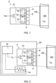
- FIG. 2 a schematic representation of an infrared sensor system 20, according to the present invention, is illustrated.
- the sensor system 20 comprises an infrared sensor 2 with substantially the same features as that of a standard infrared sensor 2, as illustrated in Figure 1 and described above.
- the sensor system 20 additionally comprises a heater 14, located proximate to the sensor 2, and a controller 16 connected to both the infrared sensor 2 and the heater device 14.
- the controller 16 is configured to operate the infrared sensor system 20 according to a method of the invention.
- the heater 14 must be located proximate to the infrared sensor 2 such that when the controller 16 operates the heater 14, the heater 14 heats the infrared sensor 2 without substantially heating a surface 105 of the object 101 at which the infrared system is directed.
- the surface 105 is that of a vacuum pump rotor, object 101.
- the heater 14 of the sensor system 20 can be separate to, or integral with the infrared sensor 2; it may be any suitable type of heater 14, for example a resistive heater.
- the infrared sensor system controller 16 is able to run an operational status check according to the first aspect, namely a method, of the invention as will now be described.
- the operational status of the infrared sensor system 20 can be determined when the surface 105 of the vacuum pump rotor 101 is either at room temperature, i.e. before the pump (not shown) has been started, or during a steady state operation, when for example the pump is running at operational speed and no gas is passing through an inlet thereof.
- the vacuum pump is in one of these two conditional states (off or at steady state)
- the net exchange of heat between the infrared sensor 2 and rotor surface 105 will be zero because they will each be at substantially the same temperature.
- the rate of heat loss from the window 8 will be lower than expected, due to the insulating effect of the debris and heat reflection back to the thermopile 4.
- the voltage generated V G will not substantially equal the expected voltage generated V E and the controller 16 will, thus, indicate that the operational status is not ideal and that the system 20 requires servicing.
- the controller 16 may also be configured to operate the system 20 according to a further aspect to provide a method of measuring the initial emissivity, E I , of a surface, and comparing this with an expected emissivity E E .
- a high emissivity coating to the surface 105 of the rotors 101 which are to have their temperatures measured by infrared sensors 2.
- High emissivity coatings ensure that accurate temperature readings can be obtained as they ensure that no heat from the infrared sensor 2 is reflected away from the surface 105 and that substantially all thermal radiation generated by the surface of the rotor 101 is directed to the infrared sensor 2.
- the voltage generated V G during the test will substantially match that of the expected voltage generated V E . If, however, the emissivity of surface 105, 105' of the coated rotor 101 or the rotor sleeve 110 is not as good as expected, the amount of heat absorbed or reflected by the surface 105, 105' during the test will differ and the voltage generated V G will be proportionally different. Thus the initial emissivity E I of the coated surface 105 or the sleeve surface 105' can be calculated.
- the emissivity measurement is within a predetermined acceptable range, for example 0.9 to 0.97, then the calculated initial emissivity E I is used by the controller 16 to calibrate future temperature readings whilst the pump is operational. If the initial emissivity measured falls outside the predetermined acceptable range, the pump will need to be serviced and the sleeve 110 replaced or coating replenished.
- a predetermined acceptable range for example 0.9 to 0.97
- the pump 1 comprises a housing or casing 19 with an inlet 3 for receiving gas and an outlet 5 for exhausting the gas conveyed through the pump 1, in use.
- a rotor 100 which comprises a number of radially outwardly extending rotor blade stages 9.
- the casing 19 defines a stator component comprising a series of stator blade stages 11 extending radially inwardly and located between each of the rotor blade stages 9 in a manner well known to those skilled in the art of turbomolecular pump design.
- the rotor 100 also comprises, proximate to the outlet 5, a series of molecular drag, or Holweck, stages 13 which lower the inlet pressure requirements of the pump backing the turbomolecular pump.
- the rotor 100 is supported for rotation at its uppermost and lowermost (as illustrated) ends with bearings 17 and 15 respectively.
- the lowermost bearings 15 comprise a ball type bearing arrangement and the uppermost bearings 17 comprise a passive magnetic bearing arrangement.
- the uppermost part of the rotor may also be protected by a set of ball type, thrust bearings (not shown) to prevent the rotor from colliding with the stationary parts of the pump in the event of a failure of the passive magnetic bearings 17.
- the rotor 100 is connected to a motor 26.
- the motor 26 is a synchronous two-pole, three-phase brushless 24 Volt DC motor contained in a stator 28.
- the motor 26 comprises three sets of motor coil windings 44 that are evenly distributed around the motor stator 28.
- the motor coil windings 44 are contained in a potting material, such as an epoxy resin with good thermal conductivity.
- a motor shaft 115 is connected to the rotor 100 for rotation thereof.
- commutation of the motor shaft 115 is controlled using an external controller 16 which, depending on the location of the poles of the magnets, turns on each of the three motor windings 44 in sequence to rotate the motor shaft 115 and thus the pump rotor 100.
- the motor 26 also comprises an integral infrared sensor system 20 comprising an infrared sensor 2.
- the sensor is shown as being contained within the potting material of the coil winding 44, but may also be located in and/or on the motor stator housing 28.
- the infrared sensor 2 is, as described above, a noncontacting surface temperature measuring sensor comprising a thermopile 4 for measuring the surface temperature T OB of an object device 101 (in this example rotor 100) by monitoring its infrared radiation emissions and a thermistor 18 for monitoring the temperature T REF of a casing 21 of the infrared sensor 2 for the purposes of temperature compensation.
- the infrared sensor 2 monitors the infrared radiation emitted from a target area 105, on the rotor 100, as shown in Figure 3 (or 102 in Figure 4 ) .
- the temperature T OB measured by the infrared sensor is compensated by an internal thermistor temperature T REF and an accurate reading of the temperature of the rotor surface 105 is obtained.
- T REF internal thermistor temperature
- the turbomolecular pump 1 if the gas load being pumped or the backing pressure at the outlet 5 remains above the levels for which the pump is designed, the rotor temperature will rise.
- the infrared sensor 2 passes a signal to the controller 16 indicative of the object rotor temperature T OB and, if above a predetermined temperature, an alarm is raised and/or the pump is slowed down to prevent damage or pump failure.
- the target scanning area 105, 102 on the rotor may have a high emissivity coating applied, such as described in US5350275 , or preferably a carbon fibre reinforced epoxy sleeve 110.
- the target scanning area is ideally on the rotor shaft 115, but it is also suitable to position the infrared sensor in the motor such that the object target surface 102 for the infrared sensor is a stator blade 11 or drag pump mechanism 13 (as illustrated in Figure 4 ).
- inventions illustrated in Figures 3 and 4 provide a further advantage over the infrared system 20 described above, by providing a motor 26 with an integral infrared sensor 2, a device in which the operational status of the sensor 2 can be checked and tested is provided.
- the motor 26 which acts as the heater device 14 and the method comprises the steps of applying a direct current to at least one motor winding to raise the temperature of the motor without causing significant rotation of the motor.
- the infrared sensor 2 may be heated without significantly heating the object surface 105.
- the voltage generated V G by the infrared sensor 2 directed at the surface may then be measured and compared with an expected generated voltage V E .
- the operational status of the sensor 2 inside the pump 1 is preferably tested/initialised while the pump 1 is at room temperature.
- the pump controller 16, or an operative, first passes a direct current through at least one of the motor coil windings 44, preferably at a higher current than the usual operating current of the coil windings 44, until a predetermined temperature rise is measured by the sensor's internal thermistor 18. Passing a current through at least one of the motor coil windings 44, or any number of them simultaneously means that the pump windings themselves heat up but the rotor 100, without a commutation signal, does not rotate. Some minor rotation might initially occur, but it will be substantially lower than the rated rotational frequency of the pump 1. Without the commutation signal the pump 1 is unable to rotate at full speed and thus no, or little, heat is generated in the rotor 100 due to gas compression.
- the sensor 2 and controller 16 should detect a difference between the motor 26 and sensor 2 internal reference temperature T REF and the object rotor 101 surface temperature T OB that would not normally be present at room temperature. If the sensor's operational efficacy has not been affected by process by-products the T REF should be greater than T OB by a known value; that is, the voltage generated by the sensor V G should not differ from the expected generated voltage V E . If, however, the sensor is coated or has been corroded in any way, or the rotor surface 105 has been coated such that its emissivity has been altered then the sensor 2 will not be able to measure the rotor surface temperature accurately so the voltages V G generated (i.e. the temperature difference measured) will differ from the expected generated voltage V E .
- the predetermined temperature rise can be achieved by either passing the direct current through at least one of the motor windings for a set period of time, as described above, or until the sensor's thermistor 18 detects that a predetermined temperature rise has been achieved.
- an unexpected rise in object temperature T OB can be attributed to a lower than expected emissivity from the target surface 105, 102.
- the unexpected rise allows the true emissivity of the rotor surface to be calculated, affecting calibration of the IR sensor system 20 once the pump 1 is fully assembled.
- turbomolecular pump 1 comprising the sensor system 20 comprising the infrared sensor 2 and a proximate heating device 14 which can also be operated as described above.
Landscapes
- Physics & Mathematics (AREA)
- General Physics & Mathematics (AREA)
- Spectroscopy & Molecular Physics (AREA)
- Engineering & Computer Science (AREA)
- General Engineering & Computer Science (AREA)
- Mechanical Engineering (AREA)
- Pathology (AREA)
- Health & Medical Sciences (AREA)
- General Health & Medical Sciences (AREA)
- Immunology (AREA)
- Analytical Chemistry (AREA)
- Chemical & Material Sciences (AREA)
- Life Sciences & Earth Sciences (AREA)
- Biochemistry (AREA)
- Microelectronics & Electronic Packaging (AREA)
- Power Engineering (AREA)
- Non-Positive Displacement Air Blowers (AREA)
- Radiation Pyrometers (AREA)
- Control Of Electric Motors In General (AREA)
- Measuring Temperature Or Quantity Of Heat (AREA)
Applications Claiming Priority (2)
| Application Number | Priority Date | Filing Date | Title |
|---|---|---|---|
| GB1615124.3A GB2553374B (en) | 2016-09-06 | 2016-09-06 | Temperature sensor for a high speed rotating machine |
| PCT/GB2017/052596 WO2018046913A1 (en) | 2016-09-06 | 2017-09-06 | Infrared temperature sensor for a high speed rotating machine |
Publications (2)
| Publication Number | Publication Date |
|---|---|
| EP3510369A1 EP3510369A1 (en) | 2019-07-17 |
| EP3510369B1 true EP3510369B1 (en) | 2025-05-21 |
Family
ID=57139779
Family Applications (1)
| Application Number | Title | Priority Date | Filing Date |
|---|---|---|---|
| EP17767885.1A Active EP3510369B1 (en) | 2016-09-06 | 2017-09-06 | Vacuum pump comprising infrared temperature sensing system |
Country Status (9)
| Country | Link |
|---|---|
| US (1) | US10837836B2 (enExample) |
| EP (1) | EP3510369B1 (enExample) |
| JP (1) | JP7273712B2 (enExample) |
| KR (1) | KR102464713B1 (enExample) |
| CN (1) | CN109642826B (enExample) |
| GB (1) | GB2553374B (enExample) |
| SG (1) | SG11201901869SA (enExample) |
| TW (1) | TWI766879B (enExample) |
| WO (1) | WO2018046913A1 (enExample) |
Families Citing this family (11)
| Publication number | Priority date | Publication date | Assignee | Title |
|---|---|---|---|---|
| EP3572730B1 (en) * | 2018-05-02 | 2023-01-04 | Elatronic Ag | Remote temperature measurement of cookware through a ceramic glass plate using an infrared sensor |
| JP7187186B2 (ja) * | 2018-06-27 | 2022-12-12 | エドワーズ株式会社 | 真空ポンプ、ステータコラム、ベースおよび真空ポンプの排気システム |
| JP7472114B2 (ja) * | 2018-09-28 | 2024-04-22 | ラム リサーチ コーポレーション | 堆積副生成物の蓄積からの真空ポンプの保護 |
| EP3557073A1 (de) * | 2019-03-07 | 2019-10-23 | Pfeiffer Vacuum Gmbh | Vakuumpumpe |
| EP3636933B1 (de) * | 2019-09-11 | 2021-11-03 | Pfeiffer Vacuum Gmbh | Verfahren zum ermitteln einer temperatur mittels eines infrarot-sensors |
| EP3653885B1 (de) * | 2019-11-06 | 2022-01-05 | Pfeiffer Vacuum Gmbh | Verfahren zum ermitteln einer zustandsinformation in einem vakuumgerät |
| TWI804846B (zh) * | 2021-04-09 | 2023-06-11 | 致揚科技股份有限公司 | 高可靠性的渦輪分子泵及其系統 |
| TWI757158B (zh) * | 2021-04-21 | 2022-03-01 | 致揚科技股份有限公司 | 高效率的渦輪分子泵裝置 |
| CN114320989B (zh) * | 2021-12-31 | 2022-12-02 | 北京中科科仪股份有限公司 | 一种分子泵测温装置、测温方法及运转部件的测温装置 |
| US12068641B2 (en) | 2022-06-15 | 2024-08-20 | Livewire Ev, Llc | Motor hotspot identification |
| CN116231972B (zh) * | 2023-01-17 | 2023-12-19 | 华南理工大学 | 绕线式感应水轮发电机转子绕组温度检测的系统与方法 |
Family Cites Families (30)
| Publication number | Priority date | Publication date | Assignee | Title |
|---|---|---|---|---|
| US4117712A (en) * | 1976-01-23 | 1978-10-03 | Armstrong Cork Company | Emissimeter and method of measuring emissivity |
| FR2391466A1 (fr) * | 1977-05-20 | 1978-12-15 | Centre Nat Etd Spatiales | Procede et appareil de mesure du facteur d'absorptivite ou d'emissivite infrarouge de materiaux |
| US4435093A (en) * | 1981-12-08 | 1984-03-06 | Bethlehem Steel Corporation | Pyrometer with sighting window cleanliness monitor |
| JPS60169727A (ja) * | 1984-02-13 | 1985-09-03 | Agency Of Ind Science & Technol | 簡易放射率計 |
| JP2527398B2 (ja) | 1992-06-05 | 1996-08-21 | 財団法人真空科学研究所 | タ―ボ分子ポンプ |
| US5645349A (en) | 1994-01-10 | 1997-07-08 | Thermoscan Inc. | Noncontact active temperature sensor |
| JPH11148487A (ja) | 1997-11-18 | 1999-06-02 | Shimadzu Corp | ターボ分子ポンプ |
| JPH11264887A (ja) * | 1998-03-17 | 1999-09-28 | Toshiba Corp | 原子炉核計装システム、このシステムを備えた原子炉出力分布監視システムおよび原子炉出力分布監視方法 |
| CN2368020Y (zh) | 1998-10-21 | 2000-03-08 | 陈朝旺 | 红外线温度测量装置 |
| JP2002202192A (ja) | 2000-10-24 | 2002-07-19 | Tokyo Electron Ltd | 温度測定方法、熱処理装置及び方法、コンピュータプログラム、並びに、放射温度計 |
| JP2003287463A (ja) * | 2002-03-28 | 2003-10-10 | Boc Edwards Technologies Ltd | 放射温度測定装置及び該放射温度測定装置を搭載したターボ分子ポンプ |
| JP2004085459A (ja) * | 2002-08-28 | 2004-03-18 | Bio Ekoonetto:Kk | 赤外線温度センサーおよびそれを用いた温度測定回路並びにその測定方法 |
| JP2004116316A (ja) * | 2002-09-24 | 2004-04-15 | Boc Edwards Technologies Ltd | 真空ポンプ |
| GB0224709D0 (en) | 2002-10-24 | 2002-12-04 | Boc Group Plc | Improvements in dry pumps |
| GB0225335D0 (en) * | 2002-10-31 | 2002-12-11 | Genevac Ltd | Temperature sensing in centrifugal evaporators |
| US7220378B2 (en) * | 2004-01-07 | 2007-05-22 | Pressco Technology Inc. | Method and apparatus for the measurement and control of both the inside and outside surface temperature of thermoplastic preforms during stretch blow molding operations |
| JP4528019B2 (ja) * | 2004-04-27 | 2010-08-18 | 株式会社大阪真空機器製作所 | 分子ポンプの温度制御装置 |
| JP4673011B2 (ja) * | 2004-07-05 | 2011-04-20 | 株式会社島津製作所 | ターボ分子ポンプの温度制御装置 |
| JP2006037739A (ja) * | 2004-07-22 | 2006-02-09 | Koyo Seiko Co Ltd | ターボ分子ポンプ装置 |
| WO2009155954A1 (de) * | 2008-06-26 | 2009-12-30 | Siemens Aktiengesellschaft | Anordnung mit einer elektrischen maschine sowie verfahren zum betreiben einer elektrischen maschine |
| ATE549610T1 (de) * | 2008-07-16 | 2012-03-15 | Siemens Ag | Anordnung mit einer elektrischen maschine sowie verfahren zum betreiben einer elektrischen maschine |
| WO2010021307A1 (ja) | 2008-08-19 | 2010-02-25 | エドワーズ株式会社 | 真空ポンプ |
| WO2011020500A1 (de) * | 2009-08-19 | 2011-02-24 | Siemens Aktiengesellschaft | Anordnung mit einer elektrischen maschine sowie verfahren zum betreiben einer elektrischen maschine |
| CN102004000B (zh) * | 2010-10-21 | 2011-10-26 | 华中科技大学 | 用于高温高压容器内转动部件的表面温度检测系统 |
| CN102150769B (zh) | 2011-05-19 | 2013-08-14 | 邓海波 | 撞击流微波加热真空闪蒸脱水浓缩机 |
| JP2013079602A (ja) * | 2011-10-04 | 2013-05-02 | Shimadzu Corp | ターボ分子ポンプ |
| JP5924414B2 (ja) * | 2012-09-24 | 2016-05-25 | 株式会社島津製作所 | ターボ分子ポンプ |
| DE102013112023A1 (de) * | 2012-11-02 | 2014-05-08 | Maxim Integrated Products, Inc. | System und Verfahren zum Reduzieren der Umgebungslichtempfindlichkeit von Infrarotdetektoren (IR-Detektoren) |
| CN203837817U (zh) * | 2014-06-04 | 2014-09-17 | 隆青强 | 一种红外测温系统探头校点装置 |
| JP2016148706A (ja) | 2015-02-10 | 2016-08-18 | コニカミノルタ株式会社 | 画像形成装置および温度測定装置 |
-
2016
- 2016-09-06 GB GB1615124.3A patent/GB2553374B/en active Active
-
2017
- 2017-09-06 US US16/330,306 patent/US10837836B2/en active Active
- 2017-09-06 WO PCT/GB2017/052596 patent/WO2018046913A1/en not_active Ceased
- 2017-09-06 EP EP17767885.1A patent/EP3510369B1/en active Active
- 2017-09-06 KR KR1020197006478A patent/KR102464713B1/ko active Active
- 2017-09-06 SG SG11201901869SA patent/SG11201901869SA/en unknown
- 2017-09-06 CN CN201780054785.2A patent/CN109642826B/zh active Active
- 2017-09-06 TW TW106130369A patent/TWI766879B/zh active
- 2017-09-06 JP JP2019533703A patent/JP7273712B2/ja active Active
Also Published As
| Publication number | Publication date |
|---|---|
| TWI766879B (zh) | 2022-06-11 |
| JP2019529949A (ja) | 2019-10-17 |
| GB201615124D0 (en) | 2016-10-19 |
| WO2018046913A1 (en) | 2018-03-15 |
| KR102464713B1 (ko) | 2022-11-07 |
| US10837836B2 (en) | 2020-11-17 |
| JP7273712B2 (ja) | 2023-05-15 |
| US20190226914A1 (en) | 2019-07-25 |
| SG11201901869SA (en) | 2019-03-28 |
| KR20190044074A (ko) | 2019-04-29 |
| EP3510369A1 (en) | 2019-07-17 |
| TW201816371A (zh) | 2018-05-01 |
| CN109642826B (zh) | 2023-08-15 |
| GB2553374A (en) | 2018-03-07 |
| GB2553374B (en) | 2021-05-12 |
| CN109642826A (zh) | 2019-04-16 |
Similar Documents
| Publication | Publication Date | Title |
|---|---|---|
| EP3510369B1 (en) | Vacuum pump comprising infrared temperature sensing system | |
| US20110200460A1 (en) | Vacuum pump | |
| US11162499B2 (en) | Vacuum pump system | |
| JP2019529949A5 (enExample) | ||
| CN107191388B (zh) | 温度控制装置以及涡轮分子泵 | |
| CN116194657B (zh) | 旋转机械的监视装置、记录有监视程序的计算机可读取的记录介质、监视方法以及旋转机械设备 | |
| CN114320989B (zh) | 一种分子泵测温装置、测温方法及运转部件的测温装置 | |
| CN113348305A (zh) | 真空泵以及真空泵的控制装置 | |
| US7575372B2 (en) | Device for contactless measurement of rotor temperatures | |
| KR102553701B1 (ko) | 진공 펌프, 당해 진공 펌프에 적용되는 온도 조절용 제어 장치, 검사용 지그, 및 온도 조절 기능부의 진단 방법 | |
| CN114060304B (zh) | 一种测温装置及方法 | |
| US20240213905A1 (en) | Method of Updating a Thermal Model of an Electric Motor | |
| JPWO2019013206A1 (ja) | エンコーダ及び駆動装置 | |
| JP2021043180A (ja) | 温度を算出するための方法 | |
| JP2025080890A (ja) | 分子ポンプ | |
| JP2022503981A (ja) | 電気モーターの上または内で結露が形成されそうであること、または、結露が既に形成されていることを検出する方法、および、電気モーターの上または内の結露の形成を防止し、かつ/または、結露を除去する方法 | |
| US20240283386A1 (en) | Method Of Determining Cooling Efficiency Of An Electric Motor | |
| KR20250121371A (ko) | 퇴적 층을 검출하는 방법 및 관련 터보분자 진공 펌프 | |
| US20180340807A1 (en) | Multi-mode sensor | |
| EP3405799A1 (en) | Reactance measurement |
Legal Events
| Date | Code | Title | Description |
|---|---|---|---|
| STAA | Information on the status of an ep patent application or granted ep patent |
Free format text: STATUS: UNKNOWN |
|
| STAA | Information on the status of an ep patent application or granted ep patent |
Free format text: STATUS: THE INTERNATIONAL PUBLICATION HAS BEEN MADE |
|
| PUAI | Public reference made under article 153(3) epc to a published international application that has entered the european phase |
Free format text: ORIGINAL CODE: 0009012 |
|
| STAA | Information on the status of an ep patent application or granted ep patent |
Free format text: STATUS: REQUEST FOR EXAMINATION WAS MADE |
|
| 17P | Request for examination filed |
Effective date: 20190326 |
|
| AK | Designated contracting states |
Kind code of ref document: A1 Designated state(s): AL AT BE BG CH CY CZ DE DK EE ES FI FR GB GR HR HU IE IS IT LI LT LU LV MC MK MT NL NO PL PT RO RS SE SI SK SM TR |
|
| AX | Request for extension of the european patent |
Extension state: BA ME |
|
| DAV | Request for validation of the european patent (deleted) | ||
| DAX | Request for extension of the european patent (deleted) | ||
| STAA | Information on the status of an ep patent application or granted ep patent |
Free format text: STATUS: EXAMINATION IS IN PROGRESS |
|
| 17Q | First examination report despatched |
Effective date: 20221014 |
|
| REG | Reference to a national code |
Free format text: PREVIOUS MAIN CLASS: G01J0005000000 Ipc: F04D0019040000 Ref country code: DE Ref legal event code: R079 Ref document number: 602017089564 Country of ref document: DE |
|
| GRAP | Despatch of communication of intention to grant a patent |
Free format text: ORIGINAL CODE: EPIDOSNIGR1 |
|
| STAA | Information on the status of an ep patent application or granted ep patent |
Free format text: STATUS: GRANT OF PATENT IS INTENDED |
|
| RIC1 | Information provided on ipc code assigned before grant |
Ipc: G01J 5/04 20060101ALI20250110BHEP Ipc: G01J 5/12 20060101ALI20250110BHEP Ipc: G01J 5/02 20060101ALI20250110BHEP Ipc: G01J 5/061 20220101ALI20250110BHEP Ipc: G01J 5/00 20060101ALI20250110BHEP Ipc: F04D 27/00 20060101ALI20250110BHEP Ipc: F04D 19/04 20060101AFI20250110BHEP |
|
| INTG | Intention to grant announced |
Effective date: 20250128 |
|
| GRAS | Grant fee paid |
Free format text: ORIGINAL CODE: EPIDOSNIGR3 |
|
| GRAA | (expected) grant |
Free format text: ORIGINAL CODE: 0009210 |
|
| STAA | Information on the status of an ep patent application or granted ep patent |
Free format text: STATUS: THE PATENT HAS BEEN GRANTED |
|
| AK | Designated contracting states |
Kind code of ref document: B1 Designated state(s): AL AT BE BG CH CY CZ DE DK EE ES FI FR GB GR HR HU IE IS IT LI LT LU LV MC MK MT NL NO PL PT RO RS SE SI SK SM TR |
|
| P01 | Opt-out of the competence of the unified patent court (upc) registered |
Free format text: CASE NUMBER: APP_17737/2025 Effective date: 20250411 |
|
| REG | Reference to a national code |
Ref country code: GB Ref legal event code: FG4D |
|
| REG | Reference to a national code |
Ref country code: CH Ref legal event code: EP |
|
| REG | Reference to a national code |
Ref country code: DE Ref legal event code: R096 Ref document number: 602017089564 Country of ref document: DE |
|
| REG | Reference to a national code |
Ref country code: IE Ref legal event code: FG4D |
|
| REG | Reference to a national code |
Ref country code: NL Ref legal event code: MP Effective date: 20250521 |
|
| PG25 | Lapsed in a contracting state [announced via postgrant information from national office to epo] |
Ref country code: PT Free format text: LAPSE BECAUSE OF FAILURE TO SUBMIT A TRANSLATION OF THE DESCRIPTION OR TO PAY THE FEE WITHIN THE PRESCRIBED TIME-LIMIT Effective date: 20250922 Ref country code: FI Free format text: LAPSE BECAUSE OF FAILURE TO SUBMIT A TRANSLATION OF THE DESCRIPTION OR TO PAY THE FEE WITHIN THE PRESCRIBED TIME-LIMIT Effective date: 20250521 Ref country code: ES Free format text: LAPSE BECAUSE OF FAILURE TO SUBMIT A TRANSLATION OF THE DESCRIPTION OR TO PAY THE FEE WITHIN THE PRESCRIBED TIME-LIMIT Effective date: 20250521 |
|
| PGFP | Annual fee paid to national office [announced via postgrant information from national office to epo] |
Ref country code: DE Payment date: 20250929 Year of fee payment: 9 |
|
| REG | Reference to a national code |
Ref country code: LT Ref legal event code: MG9D |
|
| PG25 | Lapsed in a contracting state [announced via postgrant information from national office to epo] |
Ref country code: GR Free format text: LAPSE BECAUSE OF FAILURE TO SUBMIT A TRANSLATION OF THE DESCRIPTION OR TO PAY THE FEE WITHIN THE PRESCRIBED TIME-LIMIT Effective date: 20250822 Ref country code: NO Free format text: LAPSE BECAUSE OF FAILURE TO SUBMIT A TRANSLATION OF THE DESCRIPTION OR TO PAY THE FEE WITHIN THE PRESCRIBED TIME-LIMIT Effective date: 20250821 |
|
| PG25 | Lapsed in a contracting state [announced via postgrant information from national office to epo] |
Ref country code: NL Free format text: LAPSE BECAUSE OF FAILURE TO SUBMIT A TRANSLATION OF THE DESCRIPTION OR TO PAY THE FEE WITHIN THE PRESCRIBED TIME-LIMIT Effective date: 20250521 Ref country code: PL Free format text: LAPSE BECAUSE OF FAILURE TO SUBMIT A TRANSLATION OF THE DESCRIPTION OR TO PAY THE FEE WITHIN THE PRESCRIBED TIME-LIMIT Effective date: 20250521 |
|
| PG25 | Lapsed in a contracting state [announced via postgrant information from national office to epo] |
Ref country code: BG Free format text: LAPSE BECAUSE OF FAILURE TO SUBMIT A TRANSLATION OF THE DESCRIPTION OR TO PAY THE FEE WITHIN THE PRESCRIBED TIME-LIMIT Effective date: 20250521 |
|
| PGFP | Annual fee paid to national office [announced via postgrant information from national office to epo] |
Ref country code: GB Payment date: 20250929 Year of fee payment: 9 |
|
| PG25 | Lapsed in a contracting state [announced via postgrant information from national office to epo] |
Ref country code: HR Free format text: LAPSE BECAUSE OF FAILURE TO SUBMIT A TRANSLATION OF THE DESCRIPTION OR TO PAY THE FEE WITHIN THE PRESCRIBED TIME-LIMIT Effective date: 20250521 |
|
| PGFP | Annual fee paid to national office [announced via postgrant information from national office to epo] |
Ref country code: FR Payment date: 20250925 Year of fee payment: 9 |
|
| PG25 | Lapsed in a contracting state [announced via postgrant information from national office to epo] |
Ref country code: RS Free format text: LAPSE BECAUSE OF FAILURE TO SUBMIT A TRANSLATION OF THE DESCRIPTION OR TO PAY THE FEE WITHIN THE PRESCRIBED TIME-LIMIT Effective date: 20250821 |
|
| PGFP | Annual fee paid to national office [announced via postgrant information from national office to epo] |
Ref country code: CZ Payment date: 20250825 Year of fee payment: 9 |
|
| PGFP | Annual fee paid to national office [announced via postgrant information from national office to epo] |
Ref country code: RO Payment date: 20250827 Year of fee payment: 9 |
|
| PG25 | Lapsed in a contracting state [announced via postgrant information from national office to epo] |
Ref country code: IS Free format text: LAPSE BECAUSE OF FAILURE TO SUBMIT A TRANSLATION OF THE DESCRIPTION OR TO PAY THE FEE WITHIN THE PRESCRIBED TIME-LIMIT Effective date: 20250921 |
|
| PG25 | Lapsed in a contracting state [announced via postgrant information from national office to epo] |
Ref country code: LV Free format text: LAPSE BECAUSE OF FAILURE TO SUBMIT A TRANSLATION OF THE DESCRIPTION OR TO PAY THE FEE WITHIN THE PRESCRIBED TIME-LIMIT Effective date: 20250521 |