EP3509521B1 - Vorrichtung zur vorbeugung und behandlung eines vasospasmus - Google Patents
Vorrichtung zur vorbeugung und behandlung eines vasospasmus Download PDFInfo
- Publication number
- EP3509521B1 EP3509521B1 EP17777488.2A EP17777488A EP3509521B1 EP 3509521 B1 EP3509521 B1 EP 3509521B1 EP 17777488 A EP17777488 A EP 17777488A EP 3509521 B1 EP3509521 B1 EP 3509521B1
- Authority
- EP
- European Patent Office
- Prior art keywords
- stent structure
- electrodes
- struts
- electrical conductors
- blood vessel
- Prior art date
- Legal status (The legal status is an assumption and is not a legal conclusion. Google has not performed a legal analysis and makes no representation as to the accuracy of the status listed.)
- Active
Links
Images


Classifications
-
- A—HUMAN NECESSITIES
- A61—MEDICAL OR VETERINARY SCIENCE; HYGIENE
- A61B—DIAGNOSIS; SURGERY; IDENTIFICATION
- A61B18/00—Surgical instruments, devices or methods for transferring non-mechanical forms of energy to or from the body
- A61B18/04—Surgical instruments, devices or methods for transferring non-mechanical forms of energy to or from the body by heating
- A61B18/12—Surgical instruments, devices or methods for transferring non-mechanical forms of energy to or from the body by heating by passing a current through the tissue to be heated, e.g. high-frequency current
- A61B18/14—Probes or electrodes therefor
- A61B18/1492—Probes or electrodes therefor having a flexible, catheter-like structure, e.g. for heart ablation
-
- A—HUMAN NECESSITIES
- A61—MEDICAL OR VETERINARY SCIENCE; HYGIENE
- A61N—ELECTROTHERAPY; MAGNETOTHERAPY; RADIATION THERAPY; ULTRASOUND THERAPY
- A61N1/00—Electrotherapy; Circuits therefor
- A61N1/02—Details
- A61N1/04—Electrodes
- A61N1/05—Electrodes for implantation or insertion into the body, e.g. heart electrode
- A61N1/0526—Head electrodes
- A61N1/0529—Electrodes for brain stimulation
-
- A—HUMAN NECESSITIES
- A61—MEDICAL OR VETERINARY SCIENCE; HYGIENE
- A61N—ELECTROTHERAPY; MAGNETOTHERAPY; RADIATION THERAPY; ULTRASOUND THERAPY
- A61N7/00—Ultrasound therapy
- A61N7/02—Localised ultrasound hyperthermia
-
- A—HUMAN NECESSITIES
- A61—MEDICAL OR VETERINARY SCIENCE; HYGIENE
- A61N—ELECTROTHERAPY; MAGNETOTHERAPY; RADIATION THERAPY; ULTRASOUND THERAPY
- A61N7/00—Ultrasound therapy
- A61N7/02—Localised ultrasound hyperthermia
- A61N7/022—Localised ultrasound hyperthermia intracavitary
-
- A—HUMAN NECESSITIES
- A61—MEDICAL OR VETERINARY SCIENCE; HYGIENE
- A61B—DIAGNOSIS; SURGERY; IDENTIFICATION
- A61B18/00—Surgical instruments, devices or methods for transferring non-mechanical forms of energy to or from the body
- A61B2018/00053—Mechanical features of the instrument of device
- A61B2018/0016—Energy applicators arranged in a two- or three dimensional array
-
- A—HUMAN NECESSITIES
- A61—MEDICAL OR VETERINARY SCIENCE; HYGIENE
- A61B—DIAGNOSIS; SURGERY; IDENTIFICATION
- A61B18/00—Surgical instruments, devices or methods for transferring non-mechanical forms of energy to or from the body
- A61B2018/00053—Mechanical features of the instrument of device
- A61B2018/00214—Expandable means emitting energy, e.g. by elements carried thereon
- A61B2018/00267—Expandable means emitting energy, e.g. by elements carried thereon having a basket shaped structure
-
- A—HUMAN NECESSITIES
- A61—MEDICAL OR VETERINARY SCIENCE; HYGIENE
- A61B—DIAGNOSIS; SURGERY; IDENTIFICATION
- A61B18/00—Surgical instruments, devices or methods for transferring non-mechanical forms of energy to or from the body
- A61B2018/00315—Surgical instruments, devices or methods for transferring non-mechanical forms of energy to or from the body for treatment of particular body parts
- A61B2018/00321—Head or parts thereof
-
- A—HUMAN NECESSITIES
- A61—MEDICAL OR VETERINARY SCIENCE; HYGIENE
- A61B—DIAGNOSIS; SURGERY; IDENTIFICATION
- A61B18/00—Surgical instruments, devices or methods for transferring non-mechanical forms of energy to or from the body
- A61B2018/00315—Surgical instruments, devices or methods for transferring non-mechanical forms of energy to or from the body for treatment of particular body parts
- A61B2018/00345—Vascular system
- A61B2018/00404—Blood vessels other than those in or around the heart
- A61B2018/00416—Treatment of aneurisms
-
- A—HUMAN NECESSITIES
- A61—MEDICAL OR VETERINARY SCIENCE; HYGIENE
- A61B—DIAGNOSIS; SURGERY; IDENTIFICATION
- A61B18/00—Surgical instruments, devices or methods for transferring non-mechanical forms of energy to or from the body
- A61B2018/00315—Surgical instruments, devices or methods for transferring non-mechanical forms of energy to or from the body for treatment of particular body parts
- A61B2018/00434—Neural system
- A61B2018/00446—Brain
-
- A—HUMAN NECESSITIES
- A61—MEDICAL OR VETERINARY SCIENCE; HYGIENE
- A61B—DIAGNOSIS; SURGERY; IDENTIFICATION
- A61B18/00—Surgical instruments, devices or methods for transferring non-mechanical forms of energy to or from the body
- A61B2018/00636—Sensing and controlling the application of energy
- A61B2018/00773—Sensed parameters
- A61B2018/00875—Resistance or impedance
-
- A—HUMAN NECESSITIES
- A61—MEDICAL OR VETERINARY SCIENCE; HYGIENE
- A61B—DIAGNOSIS; SURGERY; IDENTIFICATION
- A61B18/00—Surgical instruments, devices or methods for transferring non-mechanical forms of energy to or from the body
- A61B18/04—Surgical instruments, devices or methods for transferring non-mechanical forms of energy to or from the body by heating
- A61B18/12—Surgical instruments, devices or methods for transferring non-mechanical forms of energy to or from the body by heating by passing a current through the tissue to be heated, e.g. high-frequency current
- A61B18/14—Probes or electrodes therefor
- A61B2018/1405—Electrodes having a specific shape
- A61B2018/1435—Spiral
- A61B2018/1437—Spiral whereby the windings of the spiral touch each other such as to create a continuous surface
-
- A—HUMAN NECESSITIES
- A61—MEDICAL OR VETERINARY SCIENCE; HYGIENE
- A61N—ELECTROTHERAPY; MAGNETOTHERAPY; RADIATION THERAPY; ULTRASOUND THERAPY
- A61N7/00—Ultrasound therapy
- A61N2007/0004—Applications of ultrasound therapy
- A61N2007/0021—Neural system treatment
-
- A—HUMAN NECESSITIES
- A61—MEDICAL OR VETERINARY SCIENCE; HYGIENE
- A61N—ELECTROTHERAPY; MAGNETOTHERAPY; RADIATION THERAPY; ULTRASOUND THERAPY
- A61N7/00—Ultrasound therapy
- A61N2007/0004—Applications of ultrasound therapy
- A61N2007/0021—Neural system treatment
- A61N2007/003—Destruction of nerve tissue
Definitions
- the invention relates to a device with a stent structure which is intended for introduction into intracranial blood vessels of the human or animal body, the stent structure being in an expanded state in which it is able to rest against the inner wall of the blood vessel and in a compressed state in which it can be moved within a microcatheter through the blood vessel, the stent structure being connected to an insertion aid and the stent structure being able to change automatically into the expanded state after being released from the microcatheter.
- the device is used to prevent or treat a vasospasm.
- Vasospasm is a spasmodic narrowing of a blood vessel. This is associated with the risk that subsequent vessels will no longer be adequately supplied with blood (ischemia), which can lead to necrosis of the tissue supplied with blood by the vessels.
- ischemia blood
- vasospasm can occur a few days after a subarachnoid hemorrhage (SAB), often as a result of an aneurysm rupture.
- SAB subarachnoid hemorrhage
- Further causes of subarachnoid hemorrhage are traumatic brain injuries and bleeding from vascular malformations or tumors. Leaked blood in the subarachnoid space washes around the vessels running there and is considered the most important triggering factor in vasospasm.
- vasospasm is one of the main reasons for strokes and even deaths occurring after an aneurysm rupture and / or bleeding from the same or an operation in this area.
- a vasospasm is usually treated with medication, calcium channel blockers or medication that increase the NO level in the blood being used.
- medication calcium channel blockers or medication that increase the NO level in the blood being used.
- An example of a calcium channel blocker is nimodipine, which is often used after subarachnoid hemorrhage to prevent vasospasm.
- drug treatment has not inconsiderable side effects and is also costly and time-consuming.
- vasospasm Other options for treating vasospasm include intensive care measures such as increasing arterial blood pressure and increasing circulating blood volume, widening narrowed vessels with the help of a balloon, blocking the stellate ganglion and surgically destroying sympathetic nerve fibers (sympathicolysis). These treatment methods are individually inconsistent in their effectiveness. Sometimes very complex, and often not effective for a long enough period. The blockade of the stellate ganglion and the operative sympathicolysis are effective because the sympathetic nerve fibers in the wall of the cerebral arteries play a major role in the development of cerebral vasospasm.
- DE 10 2014 101 348 A1 describes a device for ablating tissue cells
- US 2015/0018818 A1 describes a device for nerve modulation or ablation
- DE 10 2011 053 021 A1 deals with a device for neuromodulation and / or nerve stimulation
- EP 2 732 784 A1 with the application of radio frequency energy to the renal artery wall.
- US 2007/129760 A1 relates to a device for intravascular neuromodulation.
- the task was therefore to make available means which allow the prevention and treatment of a vasospasm in a different way.
- This disclosure describes a device with a stent structure, which is provided for introduction into intracranial blood vessels of the human or animal body, the stent structure in an expanded state in which it is able to lie against the inner wall of the blood vessel, and a compressed state in which it can be moved within a microcatheter through the blood vessel, the stent structure being connected to an insertion aid and the stent structure being able to change automatically into the expanded state after being released from the microcatheter, the stent structure having electrical conductors, via which electrical impulses, high frequency impulses or ultrasonic impulses can be applied to nerve fibers running in the vessel wall of the blood vessel in order to temporarily or permanently reduce the function of the nerve fibers and to prevent or treat vasospasm.
- the invention is thus based on using a stent structure for the endovascular denervation of arteries supplying the brain.
- Endovascular processes for denervation of sympathetic nerve fibers are known in the area of denervation of the renal artery, but this serves to interrupt nerve fibers between the brain and kidney in order to reduce the release of substances that increase blood pressure.
- balloon catheters used for this purpose are not suitable for the intracranial area.
- impulses can be applied to the nerve fibers in the form of high frequency (HF) signals, direct current, alternating current or ultrasound.
- HF high frequency
- denervation is ultimately based on warming of the vascular wall, which leads to the deactivation or reduction of the function of the nerve fibers.
- the use of high-frequency or ultrasonic pulses is preferred insofar as energy maxima can be generated in the depths of the surrounding vessel wall, so that the nerve fibers are not targeted however, the entire vessel wall is damaged.
- the nerve fibers are those of the sympathetic nervous system.
- a single impulse application to the nerve fibers typically lasts for a period of 30 to 120 seconds, whereby the nerve fibers can be heated to 50 to 80 ° C.
- the depth of penetration of the energy into the vessel wall is, for example, 1 to 3 mm.
- the frequency is typically 300 to 4,000 kHz.
- high frequency is understood to mean electromagnetic waves with a frequency> 1 kHz, including microwaves with a frequency> 1 GHz.
- Stents also called vascular endoprostheses, are often used to treat vascular constrictions and are permanently implanted at the site of the vascular constriction in order to keep the vessel open.
- stents typically have a tubular structure and are either laser-cut, so that a surface results from struts with openings between them, or consist of a wire mesh.
- Stents can be delivered to the target site through a catheter and expanded there; in the case of self-expanding stents made of shape memory materials, this expansion and application to the inner wall of the vessel take place automatically. After final placement, only the stent itself remains at the target location; Catheters, guidewires, and other implements are removed from the blood vessel system.
- Implants with a similar structure with higher surface density are also used to close aneurysms by placing them in front of the neck of an aneurysm.
- flow diverters are also used to close aneurysms by placing them in front of the neck of an aneurysm.
- the prevention or treatment of vasospasm with the aid of a stent structure has not yet been described.
- the device according to the invention is used for the endovascular denervation of arteries supplying the brain for the prevention and treatment of bleeding-related vasospasm.
- the device is particularly flexible and can therefore be inserted into arteries inside the skull.
- the arterial blood flow is changed only so little by the device that there is no need to fear an insufficient supply of the brain.
- the device can be used once, remain in the vessel to be treated for several days or be permanently implanted.
- the effect of the device according to the invention is based on a functional reduction or interruption of the function of nerve fibers in the vessel wall of the blood vessels concerned. This can range from a temporary loss of function to permanent destruction of the nerve fibers.
- energy is transferred from the device to the vessel wall, with the energy transfer being possible by means of electrical impulses, high-frequency impulses or ultrasonic impulses. These result in at least partial sclerotherapy of the nerve fibers.
- the energy is transmitted to the vessel wall with the aid of electrodes or ultrasonic transmitters, the energy being supplied to the electrodes / ultrasonic transmitters by means of electrical conductors that are part of the stent structure.
- the electrodes which as a rule represent the ends of the electrical conductor, are usually widened in relation to the conductor.
- the electrical conductors can have round or angular widened end sections that function as electrodes.
- the stent structure is a self-expanding stent structure, ie after being released from a microcatheter, in which it is advanced to the target location, it automatically assumes an expanded state in which it is applied to the inner wall of the blood vessel concerned.
- the transition from the compressed to the expanded state should be reversible, ie the stent structure should be able to be converted from the expanded state back into the compressed state, in particular so that it can be withdrawn into the microcatheter after use and removed from the blood vessel system.
- Such self-expanding stent structures are in principle sufficiently known from the prior art, for example for keeping blood vessels open permanently in the event of vascular constrictions caused by arteriosclerosis.
- Self-expanding stent structures are typically produced from a material with shape memory properties, in particular shape memory metals, for example nickel-titanium alloys. Nitinol is used particularly frequently in this context. However, polymers with shape memory properties or other alloys are also conceivable.
- the insertion aid is typically an insertion wire, also called a guide wire.
- insertion wires are also used for implants; however, in the case of implants which are intended to remain permanently in the vascular system, the insertion wire is connected to the implant via a separation point, the separation point being intended for mechanical, thermal, electrolytic or chemical separation.
- the device according to the invention is usually only brought temporarily to the target position in order to apply energy to the vessel wall there.
- the insertion aid is preferably made of stainless steel, nitinol or a cobalt-chromium alloy.
- a device with a stent structure which can be placed permanently in the vascular system in which a detachment point is provided between the insertion aid and the stent structure, is also conceivable.
- the stent structure is connected to the insertion aid at its proximal end, even if other connections between the insertion aid and the stent structure are not excluded.
- the insertion aid or the insertion wire is preferably attached radially on the outside at the proximal end of the stent structure.
- the connection between the insertion aid and the stent structure is not located in the center of the stent structure, but rather eccentrically on or near the inner wall of the vessel. In this way, the blood flow is hindered as little as possible.
- the eccentric arrangement of the insertion aid also makes it easier to withdraw the device into the microcatheter.
- the treatment is carried out in such a way that the device according to the invention is advanced within a microcatheter to the target location, ie the location of the vasospasm or the location at which there is a risk of vasospasm occurring.
- the stent structure is then released, which then expands and rests against the inner wall of the vessel.
- impulses are applied to the nerve fibers in the vessel wall. This can be done repeatedly, even over longer periods of several hours or several days.
- the microcatheter is moved again in the distal direction to fold in the stent structure, and the Microcatheter and device withdrawn.
- the treatment described can be repeated for several consecutive days.
- proximal and distal are to be understood in such a way that when the device is introduced to the attending physician, parts pointing away from the attending physician are designated as proximal and parts pointing away from the attending physician are designated as distal.
- the device is thus typically advanced in the distal direction through a microcatheter.
- axial relates to the longitudinal axis of the device running from proximal to distal, the term “radial” to planes perpendicular thereto.
- a drug treatment can also take place, for example with nimodipine.
- This can in particular be applied intraarterially at the point at which a vasospasm is to be treated or a vasospasm is to be prevented.
- the stent structure can be composed of individual struts connected to one another.
- Such a stent structure can be produced in a known manner by laser cutting.
- it makes sense to electropolish the stent structure to make it smoother and more rounded and thus less traumatic.
- the risk of germs or other contaminants adhering is reduced.
- the stent structure can also be a mesh structure made up of individual wires that form a braid.
- the wires here typically run helically along the longitudinal axis, with wires running in opposite directions running above and below one another at the intersection points, so that honeycomb openings are formed between the wires.
- the total number of wires is preferably 8 to 64.
- the wires that form the mesh structure can be individual wires made of metal, but it is also possible to provide strands, ie several wires of small diameter which together form a filament are preferably twisted together.
- a stent structure made of interconnected struts which is produced in particular by laser cutting, compared to a mesh structure made of wires is that a stent structure made of struts tends less to contract length when expanding than a mesh structure.
- the length contraction should be kept as small as possible, since the stent structure exposes the surrounding vessel wall to additional stress during a length contraction. Since vasospasm can ultimately be traced back to stimuli that are exerted on the vessel, additional stress should be avoided during vasospasm treatment.
- the struts or wires can have a round, oval, square or rectangular cross-section, with rounding of the edges being advantageous in the case of a square or rectangular cross-section.
- a height and width of the struts / wires of 20 to 300 ⁇ m, preferably 20 to 70 ⁇ m, have proven to be advantageous, with a rectangular cross-section with rounded edges also being essentially rectangular is understood.
- the diameter should be between 20 and 300 ⁇ m, preferably between 20 and 70 ⁇ m.
- the electrical conductors can be the struts / wires themselves, the conductors can be connected to the struts / wires, or the conductors are separate components of the stent structure.
- the stent structure has a backbone running from proximal to distal, from which struts extend which, in the expanded state, form the circumference of the stent structure.
- the stent structure can for example resemble a human backbone, the struts extending from the backbone corresponding to the ribs.
- the struts emanating from the spine can essentially form a ring when they are in the expanded state, so that they rest over the entire or large parts of the circumference on the essentially circular inner wall of the blood vessel when viewed in cross section.
- two struts can each form open rings that have a gap.
- the connection points between the struts and the backbone can also be offset from one another; this reduces the risk that electrical conductors of the struts touch each other and create a short circuit.
- the struts that start from the backbone and form open rings can also be made up of two or more partial struts, i. H. two or more struts starting from the backbone run parallel to each other and end in a common end point. There is thus a gap between the end points, which are formed by opposing groups of partial struts. If a strut is composed of two partial struts, the embodiment can also be described in such a way that the two partial struts together form an arch on the backbone, the apex of the arch corresponding to the aforementioned end point.
- struts can also be made up of parallel partial struts.
- a stent structure with a plurality of narrower struts can more reliably deploy radially than a stent structure with wider struts if the stent structure is freed from the external constraint of the microcatheter.
- the angle that the struts extending from the backbone form with respect to the backbone can be a right angle, but deviations from the right angle are also possible, for example an extension to a certain extent in the proximal or distal direction.
- the angle present at the connection point between the struts and the backbone can thus be between 30 ° and 90 ° in the expanded state, the struts being able to point both distally and proximally.
- embodiments in which the struts point in the distal direction are more typical.
- the struts can have electrical conductors in order to be able to carry out the application of an impulse to the nerve fibers.
- the electrical conductors should converge at the proximal end of the stent structure and be connected to the insertion aid. Over the length of the insertion aid there is usually an electrical connection between the electrical conductors and a power source that is typically outside the body. This ensures that electrical or other pulses can be exerted through the stent structure in an externally controlled manner. In principle, however, a power source that is part of the device itself would also be conceivable; in this case, however, the power source would have to be particularly compact in order to be able to be introduced into intracranial blood vessels.
- the number of electrical conductors can vary, depending on whether only a single pair of electrodes / ultrasonic transmitter or several pairs of electrodes / ultrasonic transmitter are provided.
- the provision of several electrical conductors is advantageous insofar as in this way pulses can be applied to different points of the inner wall of the vessel, possibly also simultaneously, on the other hand, care must be taken that the entire device remains sufficiently flexible in order to be able to be advanced into narrow, intracranial blood vessels.
- the individual electrical conductors should be electrically insulated from one another so as not to cause short circuits. This is particularly true when the struts or wires forming the stent structure run relatively close to one another. Under certain circumstances it can be sufficient if electrical conductors are only electrically insulated in the areas in which they are routed closely past one another, for example at the proximal end of the stent structure where the electrical conductors transition to the insertion aid, but it is generally advantageous when there is complete insulation of the electrical conductors, possibly apart from the areas of the electrical conductors via which the pulse application takes place, that is to say usually the ends at which the electrodes are arranged.
- An embodiment is also possible in which the electrical conductors are electrically insulated, but in some places no electrical insulation is deliberately provided so that pulses can emanate from these points or between these points.
- Such an embodiment is particularly suitable for a stent structure which has a mesh structure made up of individual wires which form a braid.
- the expansion of the stent structure virtually automatically ensures that the wires, at least some of which can simultaneously fulfill a function as electrical conductors, lie against the inner wall of the vessel, thus also the points of the electrical conductors where insulation is dispensed with has been.
- One advantage of such a stent structure is that it can be used for different blood vessels with different diameters.
- Another feature of the invention is a device in which pairs of electrical or radio frequency (RF) electrodes are arranged on the perimeter of the stent structure in such a way that the electrodes, when expanded and implanted in the blood vessel, are spaced from one another by a gap, so that an applied current flow to the electrodes acts on the inner wall of the blood vessel across the gap.
- the pulse can be an electrical or a high frequency pulse.
- the embodiment is combined according to the invention with the embodiment described above, in which the stent structure has a backbone running from proximal to distal, from which struts with electrical conductors extend. In this way, pairs of struts can extend from the backbone and the electrodes are arranged at each end. In view of the small size of the stent structure overall, the distance between the electrodes is naturally also small and is generally der 1 mm.
- the electrodes have a radiopaque marking. In this way, the attending physician can recognize whether the electrodes are still at a small distance from one another, as desired, or whether they are touching, ie a short circuit is occurring. Since the struts are also subject to a radially acting force emanating from the inner wall of the vessel in the expanded state, the extent to which the stent structure is compressed also depends on the inner diameter of the blood vessel. Accordingly can For example, a certain stent structure can be used with a sufficiently large blood vessel because the electrodes have a sufficiently large gap between them, but with smaller blood vessels there may be contact between the electrodes due to the greater compression of the stent structure, which is why pulse application is not possible. Different stent structures should therefore be kept available for blood vessels with different internal diameters.
- An embodiment is also possible in which a bridge made of insulating material is provided between the electrodes. In this way a short circuit is effectively prevented. If the insulating material also has a certain flexibility, the stent structure can adapt to the inner diameter of the blood vessel. In this way, a certain stent structure can be used in blood vessels of different sizes.
- the electrodes have a radiopaque core on the inside which can serve as a marker.
- One or more radiopaque markings can also be present at other positions on the device in order to enable the attending physician to visualize the placement and deployment of the device.
- the radiopaque markings can e.g. B. made of platinum, palladium, platinum-iridium, tantalum, gold, tungsten or other radiopaque metals.
- Corresponding radiopaque markings on the ends of the stent structure, in particular on the distal end, are particularly useful.
- the stent structure sensibly has several pairs of electrodes that can generate an electrical or high-frequency pulse. In this way, an impulse can be applied to several points on the vessel wall, the application being able to take place simultaneously or one after the other. This is from Significance, as the vascular wall often has several nerve fibers, the denervation of which is important for the success of the treatment.
- the electrodes, pairs of electrodes and / or ultrasonic transmitters can be arranged offset from one another on the circumference, viewed in the longitudinal direction of the stent structure.
- the electrodes which are arranged from proximal to distal in different segments of the stent structure, also act on different sections with regard to the inner circumference of the blood vessel.
- a pulse generator can be at 12:00, a pulse generator at 3:00 a.m., a pulse generator at 6:00 a.m. and a further pulse generator at 9:00 a.m.
- Such an embodiment has the advantage that, without having to rotate the stent structure, different nerve fibers running in the longitudinal direction in the vessel wall can be detected.
- the stent structure can be advanced distally or withdrawn proximally in order to bring specific pairs of electrodes to different circumferential positions of the vessel wall and to allow the pulses to act there. This is important insofar as advancing or withdrawing the device and thus the stent structure is comparatively easy, but rotation of the stent structure is difficult to achieve, since the device is usually advanced over considerable distances into the intracranial area, which the transmission of torsional forces is made considerably more difficult.
- the stent structure has a plurality of essentially ring-shaped elements, spaced apart in the longitudinal direction of the device, each having two electrical conductors belonging to a circuit, the two electrical conductors each ending in one electrode and the two electrodes through are separated by a gap when the device is implanted in the expanded state in the blood vessel.
- struts start from a backbone running from proximal to distal, in the present case a strut from the backbone in a first direction with a first electrical conductor and a second strut in a second Direction starts with a second electrical conductor.
- the stent structure thus resembles a human one Backbone with ribs, the ends are separated from each other by a gap. It is therefore not a closed, but an open ring shape. As described above, the gaps between the individual struts for different strut pairs can be arranged offset from one another. It is also possible to fill the gap with an electrically insulating material.
- the device preferably the stent structure, should expediently have means for measuring electrical resistances, in particular means for measuring impedance, i. H. the measurement of alternating current resistances.
- a resistance measurement is important insofar as different tissues can have different electrical resistances.
- a resistance measurement is therefore useful.
- On the basis of the determined resistance for example with the aid of a data matrix, it can be determined with which defined current-voltage signal the desired effect, for example bringing about a certain temperature, can be achieved. After the treatment, the success of the treatment can be checked with another resistance measurement.
- the resistance measurement does not necessarily have to be integrated into the device according to the invention; a separate device for resistance measurement is also conceivable.
- the stent structure can be permeable, ie have openings in the radial direction, but it is also possible to provide a stent structure that has a membrane on the inside, ie the luminal side. On the abluminal side, however, the surface of the device comes into direct contact with the inner wall of the vessel. In this case, the vessel lumen is decoupled from the generally metallic wires or struts of the stent structure by means of the membrane.
- the membrane can also produce a certain electrical insulation of the electrical conductors in the luminal direction.
- the stent structure when the stent structure is present in the compressed state, the provision of an additional membrane requires additional space, so that such a stent structure can be folded up less tightly.
- the stent structure is designed to be open at the proximal end. At the distal end, the stent structure can also be open, but also closed. A stent structure that is open on both sides has the advantage that the blood flow is disturbed as little as possible and an undersupply of subsequent blood vessels and the tissue supplied by them is prevented. On the other hand, a closed structure at the distal end is more atraumatic.
- open is understood to mean that there are no struts or wires at the respective end of the stent structure and struts / wires are limited to the outer circumference of the stent structure. In the case of a closed end, however, struts or wires are also present in the center of the stent structure. Since there are openings between the struts or wires, this end is not completely tight even with a closed distal end; the blood flow can continue to take place through the openings.
- An antithrombogenic coating of the stent structure makes sense. This can affect the entire stent structure or just the inside, because the stent structure remains in the blood vessel for a certain time and during this time the formation of a thrombus in the blood vessel, which is constricted by the occurrence of vasospasm, must be avoided.
- a vascular-relaxing coating on the outside of the stent structure for example with a calcium channel blocker such as nimodipine, is advantageous.
- the diameter of the stent structure in the freely expanded state is typically in the range from 2 to 8 mm, preferably in the range from 4 to 6 mm.
- the total length of the stent structure in the expanded state is generally 5 to 50 mm, preferably 10 to 45 mm, more preferably 20 to 40 mm.
- this can, for example, be cut from a tube with a wall thickness of 25 to 70 ⁇ m; in the case of a mesh structure made of interwoven wires, the wire thickness is preferably 20 to 70 ⁇ m.
- a microcatheter through which the device can be brought to the target site in the compressed state has e.g. B. an inner diameter of 0.4 to 0.9 mm.
- the device according to the invention is used in a method for the prevention or treatment of a vasospasm.
- the The stent structure of the device according to the invention is brought with the insertion aid to the target position in the blood vessel and expands there, which is usually done by withdrawing the microcatheter in which the device is housed in the proximal direction.
- electrical impulses, high frequency impulses or ultrasonic impulses are applied to nerve fibers running in the vessel wall of the blood vessel.
- the pulse application can be repeated several times if necessary.
- the stent structure can remain in a given position between the individual pulse applications, be advanced distally or withdrawn proximally in order to capture different nerve fibers if necessary.
- the stent structure is displaced within the microcatheter, since the risk of damage to blood vessels would be too high, especially when the expanded stent structure is advanced. Injury or excessive irritation should be avoided in any case, as this can be causal for the occurrence of vasospasm.
- the stent structure is advanced or retracted into another longitudinal position in such a way that the microcatheter is first advanced in order to transfer the stent structure into the compressed state, the stent structure being picked up by the microcatheter, the microcatheter and thus also the inside of the microcatheter located stent structure is brought to the desired position and the stent structure is finally released again from the microcatheter.
- the entire device can also be removed from the blood vessel system in the meantime and reinserted later in order to be able to continue the treatment for several days, for example.
- a new device usually has to be used for each treatment.
- the device is generally removed from the blood vessel system in such a way that the microcatheter is pushed in the distal direction over the released stent structure, whereupon it folds up again and can be withdrawn proximally together with the microcatheter.
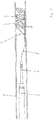
- a device 1 according to the invention is shown within a blood vessel 6 in a side view.
- the device 1 has a stent structure 2 and an insertion aid 3, which is a guide wire.
- the stent structure 2 is shown here in its expanded form implanted in the blood vessel 6.
- the stent structure 2 is advanced within the microcatheter 4 from proximal (here: left) to distal (here: right); by advancing the microcatheter 4 or withdrawing the stent structure 2, the stent structure 2 can be folded up again so tightly that it gets into the microcatheter 4 and can be removed from the blood vessel system together with it.
- the micro-catheter 4 in turn, is guided through a further catheter 5 with a larger lumen.
- the stent structure 2 itself has struts 7, each of which is essentially ring-shaped in pairs and which rest against the inner wall of the blood vessel 6.
- the struts 7 have electrical conductors which are in electrically conductive connection with the electrodes 8 at the end of the struts 7.
- a pulse for example an electrical or HF pulse, can be applied to the surrounding tissue.
- the electrode pairs 8 and thus also the gap between the electrodes are offset from one another with regard to the position in the circumference of the blood vessel, ie different rings of struts 7 apply pulses at different radial positions.
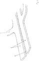
- the stent structure 2 is off Figure 1 shown in an enlarged view. It can be seen that the struts 7 each form an open ring in pairs, an electrode 8 being located at the end of each strut 7. For the individual rings of struts 7 arranged one behind the other in the longitudinal direction, the electrodes 8 are each arranged offset from one another.
- the impulses that are intended to act on different radial areas of the wall of the blood vessel and the nerve fibers running in it can be emitted simultaneously, but also at different times.
- the struts 7 start from a common backbone 9 which runs in the longitudinal direction of the stent structure 2.
- the backbone 9 itself can be divided in two, so that one half of the backbone 9 is used to supply power to the first half of the struts 7, and the second half of the backbone 9 to supply power to the second half of the struts 7.
- FIG. 3 A section of the stent structure 2 from Figure 2 is in the Figure 3 shown; it can be seen how the struts 7 are connected to the backbone 9 and that an insulation 10 is provided between the two halves of the backbone 9, which ensures that no short circuit occurs between the two halves of the backbone 9.
- a stent structure 2 is shown, which is basically the stent structure 2 from Figure 2 is similar, but on the luminal, ie inside of the Stent structure 2 a membrane 11 is provided, which separates the actual lumen of the blood vessel 6 from the stent structure 2 and thus brings about an insulation in the luminal direction.
- FIG 5 two open rings, which are arranged one behind the other and formed by struts 7 and which each extend from the backbone 9, are shown.
- the latter has 4 conductors A, B, C, D, which provide a power supply to the electrodes 8.
- the power supply via the conductors A, B on the one hand and C, D on the other hand can take place simultaneously or sequentially.
- Electrodes 8 are shown which form the ends of the electrical conductors 13.
- the electrical current is led directly via the struts 7 to the electrodes 8, ie the struts 7 are also electrical conductors 13.
- the electrodes 8 have an opening inside into which X-ray markers 12 are pressed.
- the x-ray markers 12 can consist of platinum or a platinum alloy, for example.
- the attending physician immediately recognizes in the X-ray image how the electrodes 8 which produce the pulses that are essential for the treatment are arranged.
- the doctor can check that there is no short circuit between the electrodes 8.
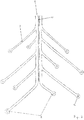
- a stent structure 2 is shown in developed form, ie the struts 7 forming an open ring were pressed into a surface and are shown here in two dimensions. It can be seen that the struts 7 have different lengths. What is achieved in this way is that the electrodes 8 are ultimately arranged offset on the inner wall of the blood vessel after they have been introduced into the blood vessel and that pulses have an effect on different sections.
Landscapes
- Health & Medical Sciences (AREA)
- Engineering & Computer Science (AREA)
- Life Sciences & Earth Sciences (AREA)
- Biomedical Technology (AREA)
- Nuclear Medicine, Radiotherapy & Molecular Imaging (AREA)
- Animal Behavior & Ethology (AREA)
- General Health & Medical Sciences (AREA)
- Public Health (AREA)
- Veterinary Medicine (AREA)
- Radiology & Medical Imaging (AREA)
- Surgery (AREA)
- Cardiology (AREA)
- Heart & Thoracic Surgery (AREA)
- Otolaryngology (AREA)
- Physics & Mathematics (AREA)
- Plasma & Fusion (AREA)
- Medical Informatics (AREA)
- Molecular Biology (AREA)
- Psychology (AREA)
- Neurosurgery (AREA)
- Neurology (AREA)
- Media Introduction/Drainage Providing Device (AREA)
- Electrotherapy Devices (AREA)
- Surgical Instruments (AREA)
- Prostheses (AREA)
Applications Claiming Priority (2)
| Application Number | Priority Date | Filing Date | Title |
|---|---|---|---|
| DE102016116871.8A DE102016116871A1 (de) | 2016-09-08 | 2016-09-08 | Vorrichtung und Verfahren zur Vorbeugung und Behandlung eines Vasospasmus |
| PCT/EP2017/072451 WO2018046592A1 (de) | 2016-09-08 | 2017-09-07 | Vorrichtung und verfahren zur vorbeugung und behandlung eines vasospasmus |
Publications (2)
| Publication Number | Publication Date |
|---|---|
| EP3509521A1 EP3509521A1 (de) | 2019-07-17 |
| EP3509521B1 true EP3509521B1 (de) | 2020-11-04 |
Family
ID=59997306
Family Applications (1)
| Application Number | Title | Priority Date | Filing Date |
|---|---|---|---|
| EP17777488.2A Active EP3509521B1 (de) | 2016-09-08 | 2017-09-07 | Vorrichtung zur vorbeugung und behandlung eines vasospasmus |
Country Status (11)
| Country | Link |
|---|---|
| US (2) | US20200129228A1 (enExample) |
| EP (1) | EP3509521B1 (enExample) |
| JP (1) | JP7072751B2 (enExample) |
| KR (1) | KR20190053871A (enExample) |
| CN (1) | CN109952068B (enExample) |
| AU (1) | AU2017324399B2 (enExample) |
| BR (1) | BR112019004503A8 (enExample) |
| CA (1) | CA3035865A1 (enExample) |
| DE (1) | DE102016116871A1 (enExample) |
| ES (1) | ES2846007T3 (enExample) |
| WO (1) | WO2018046592A1 (enExample) |
Families Citing this family (10)
| Publication number | Priority date | Publication date | Assignee | Title |
|---|---|---|---|---|
| EP3474760B1 (en) | 2016-06-27 | 2023-01-11 | Galvanize Therapeutics, Inc. | Generator and a catheter with an electrode for treating a lung passageway |
| JP7267567B2 (ja) * | 2018-10-31 | 2023-05-02 | ユニチカ株式会社 | 低誘電率ポリイミド |
| DE102021102458A1 (de) | 2021-01-26 | 2022-07-28 | Phenox Gmbh | Beschichtete medizinische Vorrichtungen |
| JP7675196B2 (ja) * | 2021-01-26 | 2025-05-12 | フェノックス ゲーエムベーハー | コーティングされた医療機器 |
| AU2022287931A1 (en) | 2021-06-10 | 2023-12-21 | Galvanize Therapeutics, Inc. | Applying pulsed electric fields in the treatment of the vasculature |
| EP4514242A4 (en) * | 2022-04-25 | 2026-03-18 | Gravity Medical Tech Inc | METHODS AND APPARATUS FOR EVALUATING AND TREATMENT OF DISEASED VESSELS |
| CN114887220A (zh) * | 2022-04-29 | 2022-08-12 | 应脉医疗科技(上海)有限公司 | 血管内支架电极阵列及其制备方法和电刺激系统 |
| DE102022114767A1 (de) | 2022-06-13 | 2023-12-14 | Phenox Gmbh | Endovaskuläre Vorrichtung mit Führungsdraht |
| EP4558103A1 (en) | 2022-07-22 | 2025-05-28 | Phenox GmbH | Apparatus and method for treating vasospasm |
| WO2024197304A2 (en) * | 2023-03-23 | 2024-09-26 | The Regents Of The University Of California | Advanced function stent system for chronic on-demand drug delivery, sonogenetic control of cells, and acoustic modulation of cell function |
Family Cites Families (29)
| Publication number | Priority date | Publication date | Assignee | Title |
|---|---|---|---|---|
| DE69330132T2 (de) * | 1993-07-23 | 2001-11-15 | Cook Inc., Bloomington | Flexibler stent mit einer aus einem materialbogen geformten konfiguration |
| US6602248B1 (en) * | 1995-06-07 | 2003-08-05 | Arthro Care Corp. | Methods for repairing damaged intervertebral discs |
| ATE339917T1 (de) * | 1996-10-23 | 2006-10-15 | Oratec Interventions Inc | Vorrichtung zur behandlung von zwischenwirbelscheiben |
| US7198635B2 (en) * | 2000-10-17 | 2007-04-03 | Asthmatx, Inc. | Modification of airways by application of energy |
| US20030158545A1 (en) * | 2000-09-28 | 2003-08-21 | Arthrocare Corporation | Methods and apparatus for treating back pain |
| US8774913B2 (en) * | 2002-04-08 | 2014-07-08 | Medtronic Ardian Luxembourg S.A.R.L. | Methods and apparatus for intravasculary-induced neuromodulation |
| US7653438B2 (en) * | 2002-04-08 | 2010-01-26 | Ardian, Inc. | Methods and apparatus for renal neuromodulation |
| US7231260B2 (en) * | 2004-05-06 | 2007-06-12 | Boston Scientific Scimed, Inc. | Intravascular self-anchoring electrode body with arcuate springs, spring loops, or arms |
| EP1962949B1 (en) * | 2005-12-20 | 2015-02-25 | The Cleveland Clinic Foundation | Apparatus for modulating the baroreflex system |
| US7949409B2 (en) * | 2007-01-30 | 2011-05-24 | Cardiac Pacemakers, Inc. | Dual spiral lead configurations |
| US7925352B2 (en) * | 2008-03-27 | 2011-04-12 | Synecor Llc | System and method for transvascularly stimulating contents of the carotid sheath |
| US9339331B2 (en) * | 2008-12-29 | 2016-05-17 | St. Jude Medical, Atrial Fibrillation Division, Inc. | Non-contact electrode basket catheters with irrigation |
| EP2568905A4 (en) * | 2010-05-12 | 2017-07-26 | Shifamed Holdings, LLC | Low profile electrode assembly |
| US9408661B2 (en) * | 2010-07-30 | 2016-08-09 | Patrick A. Haverkost | RF electrodes on multiple flexible wires for renal nerve ablation |
| DE102011053021B4 (de) * | 2010-08-26 | 2013-12-19 | Acandis Gmbh & Co. Kg | Elektrode für medizinische Anwendungen, System mit einer Elektrode und Verfahren zur Herstellung einer Elektrode |
| CN103327921B (zh) * | 2010-11-19 | 2017-02-15 | 波士顿科学西美德公司 | 肾神经检测以及消融装置 |
| EP2651500B1 (en) * | 2010-12-15 | 2016-07-20 | MED-EL Elektromedizinische Geräte GmbH | Multichannel cylindrical electrode for nerve stimulation and recording |
| EP2741815A2 (en) * | 2011-08-02 | 2014-06-18 | Samson Neurosciences Ltd. | Electrostimulation in treating cerebrovascular conditions |
| CN203122581U (zh) * | 2011-08-26 | 2013-08-14 | 王捷 | 具有肾神经标测功能的导管 |
| US20130231658A1 (en) * | 2012-03-01 | 2013-09-05 | Boston Scientific Scimed, Inc. | Expandable ablation device and methods for nerve modulation |
| US8612022B1 (en) * | 2012-09-13 | 2013-12-17 | Invatec S.P.A. | Neuromodulation catheters and associated systems and methods |
| EP2732784A1 (de) * | 2012-11-20 | 2014-05-21 | Biotronik AG | Hochfrequenz-Applikationsvorrichtung zum vaskulären Einsatz, insbesondere zur Applikation von Hochfrequenz-Energie an der Renal-Arterienwand |
| EP2999423B1 (en) * | 2013-05-20 | 2021-03-31 | Mayo Foundation For Medical Education And Research | Devices for ablation of tissue |
| WO2015006480A1 (en) * | 2013-07-11 | 2015-01-15 | Boston Scientific Scimed, Inc. | Devices and methods for nerve modulation |
| US9204929B2 (en) * | 2013-09-16 | 2015-12-08 | Biosense Webster (Israel) Ltd. | Basket catheter with deflectable spine |
| US20150105772A1 (en) * | 2013-10-14 | 2015-04-16 | Boston Scientific Scimed, Inc. | Devices and methods for nerve modulation |
| CN103750898B (zh) * | 2014-01-07 | 2016-02-17 | 先健科技(深圳)有限公司 | 一种腔内消融导管 |
| DE102014101348B4 (de) * | 2014-02-04 | 2023-04-20 | Acquandas GmbH | Medizinische Vorrichtung zur Ablation von Gewebezellen und System mit einer derartigen Vorrichtung |
| US9820664B2 (en) * | 2014-11-20 | 2017-11-21 | Biosense Webster (Israel) Ltd. | Catheter with high density electrode spine array |
-
2016
- 2016-09-08 DE DE102016116871.8A patent/DE102016116871A1/de not_active Withdrawn
-
2017
- 2017-09-07 AU AU2017324399A patent/AU2017324399B2/en active Active
- 2017-09-07 JP JP2019512651A patent/JP7072751B2/ja active Active
- 2017-09-07 WO PCT/EP2017/072451 patent/WO2018046592A1/de not_active Ceased
- 2017-09-07 KR KR1020197009523A patent/KR20190053871A/ko not_active Ceased
- 2017-09-07 CA CA3035865A patent/CA3035865A1/en not_active Abandoned
- 2017-09-07 US US16/329,869 patent/US20200129228A1/en not_active Abandoned
- 2017-09-07 CN CN201780068679.XA patent/CN109952068B/zh active Active
- 2017-09-07 EP EP17777488.2A patent/EP3509521B1/de active Active
- 2017-09-07 ES ES17777488T patent/ES2846007T3/es active Active
- 2017-09-07 BR BR112019004503A patent/BR112019004503A8/pt not_active Application Discontinuation
-
2025
- 2025-03-12 US US19/077,464 patent/US20250204981A1/en active Pending
Also Published As
| Publication number | Publication date |
|---|---|
| WO2018046592A1 (de) | 2018-03-15 |
| CN109952068A (zh) | 2019-06-28 |
| JP7072751B2 (ja) | 2022-05-23 |
| BR112019004503A2 (pt) | 2019-05-28 |
| KR20190053871A (ko) | 2019-05-20 |
| US20250204981A1 (en) | 2025-06-26 |
| US20200129228A1 (en) | 2020-04-30 |
| CA3035865A1 (en) | 2018-03-15 |
| AU2017324399B2 (en) | 2022-04-07 |
| CN109952068B (zh) | 2022-08-09 |
| EP3509521A1 (de) | 2019-07-17 |
| AU2017324399A1 (en) | 2019-05-02 |
| BR112019004503A8 (pt) | 2023-03-21 |
| ES2846007T3 (es) | 2021-07-28 |
| DE102016116871A1 (de) | 2018-03-08 |
| JP2019531118A (ja) | 2019-10-31 |
Similar Documents
| Publication | Publication Date | Title |
|---|---|---|
| EP3509521B1 (de) | Vorrichtung zur vorbeugung und behandlung eines vasospasmus | |
| EP1420701B1 (de) | Vorrichtung zur implantation von occlusionsmitteln | |
| DE60114574T2 (de) | Vorrichtung zum zugriff und zur durchführung von operationen in einer zwischenwirbelscheibe | |
| EP3463206B1 (de) | Vasospasmusbehandlung | |
| DE69719257T3 (de) | Embolisationsspirale | |
| WO2019174988A1 (de) | Thrombektomievorrichtung | |
| EP2732784A1 (de) | Hochfrequenz-Applikationsvorrichtung zum vaskulären Einsatz, insbesondere zur Applikation von Hochfrequenz-Energie an der Renal-Arterienwand | |
| EP4081135B1 (de) | Implantat zur behandlung von aneurysmen | |
| EP3610822B1 (de) | Markierungskörper und verfahren zur herstellung von diesem markierungskörper | |
| DE102018105679A1 (de) | Temporärer Verschluss von Aneurysmenhälsen | |
| DE69119515T2 (de) | Draht zum öffnen eines blockierten teils eines blutgefässes | |
| DE102020115600A1 (de) | Implantat zur Behandlung von Aneurysmen | |
| WO2021074219A1 (de) | Implantat zur behandlung von aneurysmen | |
| WO2021250281A1 (de) | Implantat zur behandlung von aneurysmen | |
| EP3781088B1 (de) | Vorrichtung zur einbringung von implantaten | |
| WO2023242086A1 (de) | Endovaskuläre vorrichtung mit führungsdraht | |
| EP4164556A2 (de) | Einführsystem für implantate zur behandlung von bifurkartionsaneurysmen | |
| EP4284309A1 (de) | Beschichtete medizinische vorrichtungen |
Legal Events
| Date | Code | Title | Description |
|---|---|---|---|
| STAA | Information on the status of an ep patent application or granted ep patent |
Free format text: STATUS: UNKNOWN |
|
| STAA | Information on the status of an ep patent application or granted ep patent |
Free format text: STATUS: THE INTERNATIONAL PUBLICATION HAS BEEN MADE |
|
| PUAI | Public reference made under article 153(3) epc to a published international application that has entered the european phase |
Free format text: ORIGINAL CODE: 0009012 |
|
| STAA | Information on the status of an ep patent application or granted ep patent |
Free format text: STATUS: REQUEST FOR EXAMINATION WAS MADE |
|
| 17P | Request for examination filed |
Effective date: 20190408 |
|
| AK | Designated contracting states |
Kind code of ref document: A1 Designated state(s): AL AT BE BG CH CY CZ DE DK EE ES FI FR GB GR HR HU IE IS IT LI LT LU LV MC MK MT NL NO PL PT RO RS SE SI SK SM TR |
|
| AX | Request for extension of the european patent |
Extension state: BA ME |
|
| DAV | Request for validation of the european patent (deleted) | ||
| DAX | Request for extension of the european patent (deleted) | ||
| GRAP | Despatch of communication of intention to grant a patent |
Free format text: ORIGINAL CODE: EPIDOSNIGR1 |
|
| STAA | Information on the status of an ep patent application or granted ep patent |
Free format text: STATUS: GRANT OF PATENT IS INTENDED |
|
| INTG | Intention to grant announced |
Effective date: 20200422 |
|
| GRAS | Grant fee paid |
Free format text: ORIGINAL CODE: EPIDOSNIGR3 |
|
| GRAA | (expected) grant |
Free format text: ORIGINAL CODE: 0009210 |
|
| STAA | Information on the status of an ep patent application or granted ep patent |
Free format text: STATUS: THE PATENT HAS BEEN GRANTED |
|
| AK | Designated contracting states |
Kind code of ref document: B1 Designated state(s): AL AT BE BG CH CY CZ DE DK EE ES FI FR GB GR HR HU IE IS IT LI LT LU LV MC MK MT NL NO PL PT RO RS SE SI SK SM TR |
|
| REG | Reference to a national code |
Ref country code: GB Ref legal event code: FG4D Free format text: NOT ENGLISH |
|
| REG | Reference to a national code |
Ref country code: CH Ref legal event code: EP |
|
| REG | Reference to a national code |
Ref country code: AT Ref legal event code: REF Ref document number: 1329818 Country of ref document: AT Kind code of ref document: T Effective date: 20201115 |
|
| REG | Reference to a national code |
Ref country code: DE Ref legal event code: R096 Ref document number: 502017008073 Country of ref document: DE |
|
| REG | Reference to a national code |
Ref country code: IE Ref legal event code: FG4D Free format text: LANGUAGE OF EP DOCUMENT: GERMAN |
|
| REG | Reference to a national code |
Ref country code: NL Ref legal event code: MP Effective date: 20201104 |
|
| PG25 | Lapsed in a contracting state [announced via postgrant information from national office to epo] |
Ref country code: NO Free format text: LAPSE BECAUSE OF FAILURE TO SUBMIT A TRANSLATION OF THE DESCRIPTION OR TO PAY THE FEE WITHIN THE PRESCRIBED TIME-LIMIT Effective date: 20210204 Ref country code: GR Free format text: LAPSE BECAUSE OF FAILURE TO SUBMIT A TRANSLATION OF THE DESCRIPTION OR TO PAY THE FEE WITHIN THE PRESCRIBED TIME-LIMIT Effective date: 20210205 Ref country code: FI Free format text: LAPSE BECAUSE OF FAILURE TO SUBMIT A TRANSLATION OF THE DESCRIPTION OR TO PAY THE FEE WITHIN THE PRESCRIBED TIME-LIMIT Effective date: 20201104 Ref country code: PT Free format text: LAPSE BECAUSE OF FAILURE TO SUBMIT A TRANSLATION OF THE DESCRIPTION OR TO PAY THE FEE WITHIN THE PRESCRIBED TIME-LIMIT Effective date: 20210304 Ref country code: RS Free format text: LAPSE BECAUSE OF FAILURE TO SUBMIT A TRANSLATION OF THE DESCRIPTION OR TO PAY THE FEE WITHIN THE PRESCRIBED TIME-LIMIT Effective date: 20201104 |
|
| PG25 | Lapsed in a contracting state [announced via postgrant information from national office to epo] |
Ref country code: BG Free format text: LAPSE BECAUSE OF FAILURE TO SUBMIT A TRANSLATION OF THE DESCRIPTION OR TO PAY THE FEE WITHIN THE PRESCRIBED TIME-LIMIT Effective date: 20210204 Ref country code: SE Free format text: LAPSE BECAUSE OF FAILURE TO SUBMIT A TRANSLATION OF THE DESCRIPTION OR TO PAY THE FEE WITHIN THE PRESCRIBED TIME-LIMIT Effective date: 20201104 Ref country code: LV Free format text: LAPSE BECAUSE OF FAILURE TO SUBMIT A TRANSLATION OF THE DESCRIPTION OR TO PAY THE FEE WITHIN THE PRESCRIBED TIME-LIMIT Effective date: 20201104 Ref country code: IS Free format text: LAPSE BECAUSE OF FAILURE TO SUBMIT A TRANSLATION OF THE DESCRIPTION OR TO PAY THE FEE WITHIN THE PRESCRIBED TIME-LIMIT Effective date: 20210304 Ref country code: PL Free format text: LAPSE BECAUSE OF FAILURE TO SUBMIT A TRANSLATION OF THE DESCRIPTION OR TO PAY THE FEE WITHIN THE PRESCRIBED TIME-LIMIT Effective date: 20201104 |
|
| REG | Reference to a national code |
Ref country code: LT Ref legal event code: MG9D |
|
| PG25 | Lapsed in a contracting state [announced via postgrant information from national office to epo] |
Ref country code: HR Free format text: LAPSE BECAUSE OF FAILURE TO SUBMIT A TRANSLATION OF THE DESCRIPTION OR TO PAY THE FEE WITHIN THE PRESCRIBED TIME-LIMIT Effective date: 20201104 |
|
| REG | Reference to a national code |
Ref country code: ES Ref legal event code: FG2A Ref document number: 2846007 Country of ref document: ES Kind code of ref document: T3 Effective date: 20210728 |
|
| PG25 | Lapsed in a contracting state [announced via postgrant information from national office to epo] |
Ref country code: CZ Free format text: LAPSE BECAUSE OF FAILURE TO SUBMIT A TRANSLATION OF THE DESCRIPTION OR TO PAY THE FEE WITHIN THE PRESCRIBED TIME-LIMIT Effective date: 20201104 Ref country code: EE Free format text: LAPSE BECAUSE OF FAILURE TO SUBMIT A TRANSLATION OF THE DESCRIPTION OR TO PAY THE FEE WITHIN THE PRESCRIBED TIME-LIMIT Effective date: 20201104 Ref country code: LT Free format text: LAPSE BECAUSE OF FAILURE TO SUBMIT A TRANSLATION OF THE DESCRIPTION OR TO PAY THE FEE WITHIN THE PRESCRIBED TIME-LIMIT Effective date: 20201104 Ref country code: SM Free format text: LAPSE BECAUSE OF FAILURE TO SUBMIT A TRANSLATION OF THE DESCRIPTION OR TO PAY THE FEE WITHIN THE PRESCRIBED TIME-LIMIT Effective date: 20201104 Ref country code: SK Free format text: LAPSE BECAUSE OF FAILURE TO SUBMIT A TRANSLATION OF THE DESCRIPTION OR TO PAY THE FEE WITHIN THE PRESCRIBED TIME-LIMIT Effective date: 20201104 Ref country code: RO Free format text: LAPSE BECAUSE OF FAILURE TO SUBMIT A TRANSLATION OF THE DESCRIPTION OR TO PAY THE FEE WITHIN THE PRESCRIBED TIME-LIMIT Effective date: 20201104 |
|
| REG | Reference to a national code |
Ref country code: DE Ref legal event code: R097 Ref document number: 502017008073 Country of ref document: DE |
|
| PG25 | Lapsed in a contracting state [announced via postgrant information from national office to epo] |
Ref country code: DK Free format text: LAPSE BECAUSE OF FAILURE TO SUBMIT A TRANSLATION OF THE DESCRIPTION OR TO PAY THE FEE WITHIN THE PRESCRIBED TIME-LIMIT Effective date: 20201104 |
|
| PLAA | Information modified related to event that no opposition was filed |
Free format text: ORIGINAL CODE: 0009299DELT |
|
| STAA | Information on the status of an ep patent application or granted ep patent |
Free format text: STATUS: NO OPPOSITION FILED WITHIN TIME LIMIT |
|
| PLBE | No opposition filed within time limit |
Free format text: ORIGINAL CODE: 0009261 |
|
| R26N | No opposition filed (corrected) |
Effective date: 20210805 |
|
| RAP2 | Party data changed (patent owner data changed or rights of a patent transferred) |
Owner name: FEMTOS GMBH |
|
| 26N | No opposition filed |
Effective date: 20210805 |
|
| PG25 | Lapsed in a contracting state [announced via postgrant information from national office to epo] |
Ref country code: NL Free format text: LAPSE BECAUSE OF FAILURE TO SUBMIT A TRANSLATION OF THE DESCRIPTION OR TO PAY THE FEE WITHIN THE PRESCRIBED TIME-LIMIT Effective date: 20201104 Ref country code: AL Free format text: LAPSE BECAUSE OF FAILURE TO SUBMIT A TRANSLATION OF THE DESCRIPTION OR TO PAY THE FEE WITHIN THE PRESCRIBED TIME-LIMIT Effective date: 20201104 |
|
| PG25 | Lapsed in a contracting state [announced via postgrant information from national office to epo] |
Ref country code: SI Free format text: LAPSE BECAUSE OF FAILURE TO SUBMIT A TRANSLATION OF THE DESCRIPTION OR TO PAY THE FEE WITHIN THE PRESCRIBED TIME-LIMIT Effective date: 20201104 |
|
| REG | Reference to a national code |
Ref country code: DE Ref legal event code: R081 Ref document number: 502017008073 Country of ref document: DE Owner name: FEMTOS GMBH, DE Free format text: FORMER OWNER: PHENOX GMBH, 44801 BOCHUM, DE |
|
| REG | Reference to a national code |
Ref country code: BE Ref legal event code: MM Effective date: 20210930 |
|
| PG25 | Lapsed in a contracting state [announced via postgrant information from national office to epo] |
Ref country code: IS Free format text: LAPSE BECAUSE OF FAILURE TO SUBMIT A TRANSLATION OF THE DESCRIPTION OR TO PAY THE FEE WITHIN THE PRESCRIBED TIME-LIMIT Effective date: 20210304 Ref country code: MC Free format text: LAPSE BECAUSE OF FAILURE TO SUBMIT A TRANSLATION OF THE DESCRIPTION OR TO PAY THE FEE WITHIN THE PRESCRIBED TIME-LIMIT Effective date: 20201104 |
|
| PG25 | Lapsed in a contracting state [announced via postgrant information from national office to epo] |
Ref country code: LU Free format text: LAPSE BECAUSE OF NON-PAYMENT OF DUE FEES Effective date: 20210907 Ref country code: BE Free format text: LAPSE BECAUSE OF NON-PAYMENT OF DUE FEES Effective date: 20210930 |
|
| REG | Reference to a national code |
Ref country code: GB Ref legal event code: 732E Free format text: REGISTERED BETWEEN 20220721 AND 20220727 |
|
| PG25 | Lapsed in a contracting state [announced via postgrant information from national office to epo] |
Ref country code: CY Free format text: LAPSE BECAUSE OF FAILURE TO SUBMIT A TRANSLATION OF THE DESCRIPTION OR TO PAY THE FEE WITHIN THE PRESCRIBED TIME-LIMIT Effective date: 20201104 |
|
| P01 | Opt-out of the competence of the unified patent court (upc) registered |
Effective date: 20230526 |
|
| PG25 | Lapsed in a contracting state [announced via postgrant information from national office to epo] |
Ref country code: HU Free format text: LAPSE BECAUSE OF FAILURE TO SUBMIT A TRANSLATION OF THE DESCRIPTION OR TO PAY THE FEE WITHIN THE PRESCRIBED TIME-LIMIT; INVALID AB INITIO Effective date: 20170907 |
|
| REG | Reference to a national code |
Ref country code: AT Ref legal event code: MM01 Ref document number: 1329818 Country of ref document: AT Kind code of ref document: T Effective date: 20220907 |
|
| PG25 | Lapsed in a contracting state [announced via postgrant information from national office to epo] |
Ref country code: AT Free format text: LAPSE BECAUSE OF NON-PAYMENT OF DUE FEES Effective date: 20220907 |
|
| PG25 | Lapsed in a contracting state [announced via postgrant information from national office to epo] |
Ref country code: MK Free format text: LAPSE BECAUSE OF FAILURE TO SUBMIT A TRANSLATION OF THE DESCRIPTION OR TO PAY THE FEE WITHIN THE PRESCRIBED TIME-LIMIT Effective date: 20201104 |
|
| PG25 | Lapsed in a contracting state [announced via postgrant information from national office to epo] |
Ref country code: MT Free format text: LAPSE BECAUSE OF FAILURE TO SUBMIT A TRANSLATION OF THE DESCRIPTION OR TO PAY THE FEE WITHIN THE PRESCRIBED TIME-LIMIT Effective date: 20201104 |
|
| REG | Reference to a national code |
Ref country code: CH Ref legal event code: U11 Free format text: ST27 STATUS EVENT CODE: U-0-0-U10-U11 (AS PROVIDED BY THE NATIONAL OFFICE) Effective date: 20251001 |
|
| PGFP | Annual fee paid to national office [announced via postgrant information from national office to epo] |
Ref country code: DE Payment date: 20250929 Year of fee payment: 9 |
|
| PGFP | Annual fee paid to national office [announced via postgrant information from national office to epo] |
Ref country code: IT Payment date: 20250919 Year of fee payment: 9 |
|
| PGFP | Annual fee paid to national office [announced via postgrant information from national office to epo] |
Ref country code: GB Payment date: 20250929 Year of fee payment: 9 |
|
| PGFP | Annual fee paid to national office [announced via postgrant information from national office to epo] |
Ref country code: FR Payment date: 20250925 Year of fee payment: 9 |
|
| PGFP | Annual fee paid to national office [announced via postgrant information from national office to epo] |
Ref country code: IE Payment date: 20250929 Year of fee payment: 9 |
|
| PG25 | Lapsed in a contracting state [announced via postgrant information from national office to epo] |
Ref country code: TR Free format text: LAPSE BECAUSE OF FAILURE TO SUBMIT A TRANSLATION OF THE DESCRIPTION OR TO PAY THE FEE WITHIN THE PRESCRIBED TIME-LIMIT Effective date: 20201104 |
|
| PGFP | Annual fee paid to national office [announced via postgrant information from national office to epo] |
Ref country code: CH Payment date: 20251001 Year of fee payment: 9 |
|
| PGFP | Annual fee paid to national office [announced via postgrant information from national office to epo] |
Ref country code: ES Payment date: 20251001 Year of fee payment: 9 |