EP3501681A1 - Tool clamping device for a machine tool and machine tool - Google Patents
Tool clamping device for a machine tool and machine tool Download PDFInfo
- Publication number
- EP3501681A1 EP3501681A1 EP17210466.3A EP17210466A EP3501681A1 EP 3501681 A1 EP3501681 A1 EP 3501681A1 EP 17210466 A EP17210466 A EP 17210466A EP 3501681 A1 EP3501681 A1 EP 3501681A1
- Authority
- EP
- European Patent Office
- Prior art keywords
- tool
- clamping
- clamping device
- membrane
- actuator
- Prior art date
- Legal status (The legal status is an assumption and is not a legal conclusion. Google has not performed a legal analysis and makes no representation as to the accuracy of the status listed.)
- Withdrawn
Links
Images


Classifications
-
- B—PERFORMING OPERATIONS; TRANSPORTING
- B21—MECHANICAL METAL-WORKING WITHOUT ESSENTIALLY REMOVING MATERIAL; PUNCHING METAL
- B21D—WORKING OR PROCESSING OF SHEET METAL OR METAL TUBES, RODS OR PROFILES WITHOUT ESSENTIALLY REMOVING MATERIAL; PUNCHING METAL
- B21D5/00—Bending sheet metal along straight lines, e.g. to form simple curves
- B21D5/02—Bending sheet metal along straight lines, e.g. to form simple curves on press brakes without making use of clamping means
- B21D5/0209—Tools therefor
- B21D5/0236—Tool clamping
- B21D5/0245—Fluid operated
-
- B—PERFORMING OPERATIONS; TRANSPORTING
- B25—HAND TOOLS; PORTABLE POWER-DRIVEN TOOLS; MANIPULATORS
- B25B—TOOLS OR BENCH DEVICES NOT OTHERWISE PROVIDED FOR, FOR FASTENING, CONNECTING, DISENGAGING OR HOLDING
- B25B5/00—Clamps
- B25B5/06—Arrangements for positively actuating jaws
- B25B5/061—Arrangements for positively actuating jaws with fluid drive
- B25B5/065—Arrangements for positively actuating jaws with fluid drive involving the use of flexible pressure bags or diaphragms
-
- B—PERFORMING OPERATIONS; TRANSPORTING
- B25—HAND TOOLS; PORTABLE POWER-DRIVEN TOOLS; MANIPULATORS
- B25B—TOOLS OR BENCH DEVICES NOT OTHERWISE PROVIDED FOR, FOR FASTENING, CONNECTING, DISENGAGING OR HOLDING
- B25B1/00—Vices
- B25B1/24—Details, e.g. jaws of special shape, slideways
- B25B1/2405—Construction of the jaws
- B25B1/241—Construction of the jaws characterised by surface features or material
- B25B1/2415—Construction of the jaws characterised by surface features or material being composed of a plurality of parts adapting to the shape of the workpiece
- B25B1/2421—Construction of the jaws characterised by surface features or material being composed of a plurality of parts adapting to the shape of the workpiece the parts having a linear movement
-
- F—MECHANICAL ENGINEERING; LIGHTING; HEATING; WEAPONS; BLASTING
- F15—FLUID-PRESSURE ACTUATORS; HYDRAULICS OR PNEUMATICS IN GENERAL
- F15B—SYSTEMS ACTING BY MEANS OF FLUIDS IN GENERAL; FLUID-PRESSURE ACTUATORS, e.g. SERVOMOTORS; DETAILS OF FLUID-PRESSURE SYSTEMS, NOT OTHERWISE PROVIDED FOR
- F15B15/00—Fluid-actuated devices for displacing a member from one position to another; Gearing associated therewith
- F15B15/08—Characterised by the construction of the motor unit
- F15B15/10—Characterised by the construction of the motor unit the motor being of diaphragm type
Definitions
- the invention relates to a tool clamping device for a machine tool, a machine tool having at least one tool clamping device and a system comprising a machine tool, at least one tool clamping device and at least one tool.
- the invention relates to the clamping of the tools by means of a pressurizable, flat actuator, such as a membrane.
- a machine tool is used to manufacture and process workpieces using tools and may also be referred to as a processing machine.
- machine tools for example, metal or sheet metal processing machines, in particular bending machines or presses such as press brakes are considered here.
- the replaceable tools are usually fixed by a clamp in a tool holder.
- US 2011/0247389 A1 discloses tool clamping with a mechanical transmission element, such as a lever or linkage.
- the transmission element can be actuated electrically, pneumatically, hydraulically or with a magnet.
- the construction is mechanically complex.
- US 2004/0187552 A1 discloses a tool clamping by means of a bellows or hose, which runs longitudinally to the tool. If the hose is pressurized, it expands and clamps the tool with the help of wedges. This solution has the disadvantage that in case of leakage the whole hose unit including the connections has to be exchanged. The hose solution is complex and costly.
- the invention is based on the object to avoid the disadvantages of the prior art and to provide an improved fastening device.
- the tool clamping device proposes a separation of the fluid guide, that is the fluid space, from the actual movement of the actuator.
- a fluid chamber with openings and on the other hand, the openings occluding actuators are provided.
- This two-part solution allows a simple construction and a single replacement of an actuator, such as a membrane.
- a high pressure force can be provided with low installation space and low cost.
- the actuator is flat, that is, it has a flat or substantially planar, for example, arched shape or surface.
- the actuator is designed as a membrane, in particular as a fabric-reinforced membrane.
- the structure of the membrane may be multi-layered, for example with rubber and fabric inserts, so that high pressures can be absorbed.
- a membrane allows a thin construction and a simple mechanical structure, as a membrane replaces many moving parts.
- the fluid space and a guide for the clamping element are arranged in a base body. This allows a simple production with round holes for the clamping elements or pistons and with straight shoulders or recesses for the fluid space.
- a fluid connection communicating with the fluid chamber is arranged on the base body.
- the separation of the fluid connection from the actuator or the membrane allows a simple structure and facilitates the replacement of the actuator or the membrane.
- the clamping element has one or more actuatable by the actuator piston and one or more arranged in the clamping direction in front of the piston wedges.
- a plurality of pistons spaced apart in a longitudinal direction actuate a longitudinally extending wedge or carrier longitudinal wedge. It may be a modular structure of individual segments, which can be strung together arbitrarily arranged.
- the plurality of pistons or clamping elements can be actuated jointly by a plurality of actuators or membranes, which are each directly assigned to a piston, or a single actuator or membrane.
- the actuator is designed as a circular disk membrane.
- the individual plate membranes have the advantage that they can be replaced individually in case of pressure loss or leakage.
- applications are possible in which the actuators are actuated individually, which then requires separate fluid supplies. Due to the design of the actuator or actuators as a disk membrane, the stroke of the actuator (s) can be increased in a simple manner. It is also possible to use actuators with different strokes so that an individual stroke profile can be set in the longitudinal direction.
- the plate diaphragm is arranged in the clamping direction spaced from the opening so that it can deflect in the clamping direction and in the opposite direction.
- the membrane may be made of a stretchable material that expands in both directions.
- the membrane can to a certain extent be equipped with an excess of material, so that the excess material bulges in both directions. Excess material here means that the extent of the membrane, here the diameter of the circular plate membrane, is greater than the extent or the diameter of the attachment of the membrane.
- a plurality of openings are arranged in the fluid space and that a disk membrane and a clamping element are arranged at each opening.
- a common clamping element may be provided in the region of all or some openings or plate membranes.
- the actuator is designed as a band membrane.
- a ribbon or flat membrane is inexpensive to manufacture and easy to fix due to the rectangular shape and size.
- the band membrane is arranged on a front side in the clamping direction of a base body of the tool clamping device, that it can deflect only in the clamping direction. This allows a flat construction with small dimensions, but reduces the available hub.
- a base body of the tool clamping device has a rear part in the clamping direction with the fluid space and a front part for guiding the or the clamping elements and that the band membrane is secured between the two parts.
- At least one return spring is provided for the clamping element, which counteracts the clamping direction against the clamping element. In this way, it is ensured that the clamping element moves back after movement through the actuator or the membrane and after removal of pressure.
- two return springs per clamping element are provided.
- a machine tool according to the invention in particular a bending machine, press or a press brake, with a receptacle for a tool, comprises at least one tool clamping device as described above, in particular as a clamping device for an upper tool, and / or at least one tool clamping device as described above, in particular as a clamping device for a lower tool.
- the two variants of membrane clamping described above namely the plate membrane variant and the band membrane variant, can be used individually and mixed, and in each case for the upper tool and the lower tool. Since the tape membrane variant can have a smaller overall depth, it can preferably be used for narrowly dimensioned Mounting positions such as used for lower tools. Otherwise, the same advantages and modifications apply as previously described.
- the system according to the invention comprises a machine tool as described above, at least one tool clamping device as described above and at least one tool, in particular a bending tool.
- a machine tool as described above
- at least one tool clamping device as described above
- at least one tool in particular a bending tool.
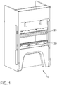
- FIG. 1 shows a perspective view of a machine tool 10.
- a machine tool 10 is used for the manufacture and processing of workpieces using tools.
- machine tools for example, metal or sheet metal processing machines, in particular bending machines or presses such as press brakes are considered here.
- a punch or an upper tool 20 presses a metal sheet into a die or a lower tool 30, which determines the bending angle.
- the reference numeral 30 may also denote a Unterwerkmaschineklemmung without tools. Most of the lower tool 30 has a V-shaped opening and the upper tool 20 has a wedge or a tip. Between the two tools 20 and 30, a sheet or often conical workpiece is placed. If the bending punch is lowered with a certain force, the workpiece is pressed into the opening of the lower tool 30 and bent to the required angle.
- FIG. 2 shows a side sectional view of a tool clamping device 200 in the open position, which serves for the clamping attachment of a tool, in this case an upper tool 20.
- the tool clamp 200 may also hold a lower tool.
- the tool 20 can be changed, that is, a tool 20 can be inserted or removed.
- the tool clamping device 200 comprises a longitudinal, in the representation of FIG. 2 into the image plane, basic body 202 whose length corresponds approximately to the width of the machine tool 10. On the main body 202, the tool clamping device 200 is mounted in the machine tool 10.
- a receiving space 204 for the tool 20 is provided in the main body 202.
- a spring 206 By means of a spring 206, the tool 20 can be secured against falling out even in the open state of the tool clamping device 200, accordingly, the tool 20 can be securely hung by means of the spring 206.
- a clamping wedge 208 which can engage in a corresponding recess of the tool 20, is fastened to a carrier plate 210.
- the support plate 210 is movable by a plurality of pistons 212, one of which is shown, in a clamping direction K. It is possible to attach the clamping wedge 208 directly, that is to say without a carrier plate 210, to the pistons 212.
- the spring-loaded clamping wedge 208 serves as a compensation element for tool tolerances and for clamping and pulling up the tool 20 to the main body 202.
- a Such clamping element may include the carrier plate 210 and the piston 212 in addition to the clamping wedge 208.
- the piston 212 is located in a guide 214.
- the guide 214 is formed as a round hole in the body and may, for example, comprise a running or guide bushing located in the hole.
- the cross section of the guide 214 corresponds to the cross section of the piston 212 and may have a different cross section instead of the round cross section shown here.
- a fluid space 216 running essentially perpendicular to the clamping direction K is provided with at least one opening 218 in the clamping direction K.
- the fluid space 216 serves to guide a fluid such as compressed air or hydraulic oil.
- the fluid space 216 extends in the longitudinal direction and a plurality of openings 218 are provided at a distance from one another, wherein a piston 212 is provided in the region of each opening 218.
- the opening 218 is sealingly closed with a pressurizable, flat actuator in the form of a membrane 220.
- the membrane 220 may be fabric reinforced and constructed in multiple layers.
- the membrane 220 is formed as a circular disk membrane. This means that a separate membrane 220 is provided or assigned for each opening 218 and thus for each piston 212.
- the opening 218 has a cross section or diameter which is slightly larger than a rear side 222 of the piston 212 opposite the clamping direction K. This means that the fluid space 216 also has an at least as large cross section. In this way, the membrane 220 can be uniformly charged with the fluid and moved. Alternatively, a smaller opening or a smaller fluid space can be provided, which is then aligned centrally with the piston 212.
- the membrane 220 is arranged with a mounting plate or ring 224 so in the clamping direction K spaced from the opening 218 that it can deflect in the clamping direction K and in the opposite direction. That is, the membrane 220 is in the open position shown here in the fluid space 216, so that the piston 212 is spaced from the tool 20 by a gap S. In order for the membrane 220 to move into the fluid space 216, it is spaced from the opening 218 and / or the fluid space 216 has a corresponding depth.
- the membrane 220 is installed in a solid housing so that it can swing into one or as shown in both directions. Thus, there are two separate spaces which are separated by the membrane 220. Thus, no fluid can flow through the membrane 220.
- the piston 212 with its backside 222 and the piston-side space with the mounting ring 224 are configured so that the membrane 220 can extend like sharp edges when expanded without hindrance, allowing for unlimited expansion and bursting of the diaphragm 220 at high pressures prevent.
- the diaphragm 220 swings out, pushes the piston 212 in the clamping direction K in front of it and can cleanly engage in the other space and on the piston 212.
- the stroke is terminated.
- the stroke is limited to the specifications of the membrane. Plate diaphragms usually reach strokes of 0.3 x effective diameter, so that a stroke of 9 mm can be achieved with an effective diameter of 30 mm.
- FIG. 3 11 shows the tool clamping device 200 in the closed position, that is, with fluid-filled fluid space 216, pressurized and bulging diaphragm 220, and piston 212 pushed out by the diaphragm. Accordingly, the tool 20 is interposed between the support plate 210 and a mating surface 226 under the engagement of wedge 208 fixed. The gap S is now closed, that is, its width is zero.
- the machine tool 10 is ready.
- the fluid space is depressurized, so that the piston 212 can move back and release the tool 20.
- This can be supported by one or more springs.
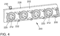
- FIG. 4 shows a schematic perspective view of a rear part 228 of the tool clamping device 200th
- all 60mm pistons 212 are arranged with a diameter of 20mm. These pistons 212 press the clamping wedge 208, which pulls the tool during the clamping process up, firmly against the opposite side of the groove in the body.
- the clamping wedge 208 acts like a spring and ensures a firm clamping of even narrow tools between the piston pressure points.
- the pistons 212 get their pressure force respectively through the Pressurized plate membrane 220. This is held by a sheet, which allows the curvature of the membrane 220 in the fluid space 216. At fluid pressure, the diaphragm 220 bulges in the other direction, that is, in the clamping direction, and presses against the piston 212.
- the rear part 228 serves to catch the opposing forces and for fluid guidance. In the intended piston diameter of, for example, 20 to 30 mm and a pressure of about 35 bar in this example per meter about 29000 N clamping force can be achieved.
- a pressure or fluid port 230 is disposed on the rear portion 228 and thus separated from the membranes 220, allowing easy replacement of both the membranes 220 and the fluid port 230.
- FIG. 5 shows a side sectional view of a second example of a tool clamping device 500 in the open position.
- a table base 502 carries a base 504 of the tool clamp 500.
- a longitudinal fluid space 506 is provided, for example, in the form of an elongated recess.
- an actuator is arranged, for example in the form of a membrane 508 covering the entire front side.
- the membrane 508 sealingly seals openings 510 of the fluid space 506.
- a plurality of clamping elements for example in the form of pistons 512, are arranged in front of the diaphragm 508.
- the pistons 512 are movably arranged in a guide 514 and, actuated by the diaphragm 508, are displaceable in the clamping direction K.
- the membrane 508 may cover all openings 510 of the fluid space 506. It can also be provided several modules that can be attached to each other. Then each module can have its own flat or ribbon membrane.
- the fluid space 506 is depressurized, so that the membrane 508 lies flat against the main body 504. Accordingly, the piston 512 is spaced from the tool 30 by a gap S.
- the tool clamping device 500 is shown here in conjunction with a lower tool 30, but it can also be used for an upper tool.
- FIG. 6 shows a side sectional view of the second example of the tool clamping device 500 in the closed position.
- the fluid chamber 506 is pressurized, so that the diaphragm 508 is bulged and thus the piston 512 presses in the clamping direction K until it rests against the tool 30, which forms a stop. As a result, the tool 30 is clamped between the piston 512 and a mating surface 516.
- a simple flat membrane can be installed here.
- Such a membrane allows strokes of 0.1x effective diameter, which, however, refers to the oscillation forward and backward. Since the membrane 508 is installed flat, only a swing in one direction is possible, so that halves the possible stroke. For example, assuming an effective diameter of 17mm results in a stroke of 0.85mm.
- FIG. 7 shows a schematic perspective view of the main body 504 of the second example of the tool clamping device 500th
- a pressure or fluid port 518 is disposed on the body 504 and thus separated from the diaphragms 508, allowing easy replacement of both the diaphragm 508 and the fluid port 518.
- the tool clamping device 500 used here as the lower tool clamping consists of two halves. A back side with the main body 504, in which the fluid guide 506 is located, and a front side, which receives the pressure piston 512.
- the front is sturdy because it not only clamps, but also rest the tools.
- a back pressure spring 520 is installed per piston.
- a pressure of 35 bar and a piston distance of 23 mm results in a force of about 30,000 N per meter.
- the advantages of the tool clamping device 500 are the simple design with few different components, the low system pressure of 35 bar and an interchangeability with existing systems, so that no table changes are necessary.
- the machine tool 10 in particular a press or a press brake, can, as described above, have a tool clamping device 200 for an upper tool 20 and a tool clamping device 500 for a lower tool 30.
- the two tool clamping devices 200 and 500 may be reversed, or two tool clamping devices 200 and 500 may be provided, respectively.
- a system for clamping tools may include a machine tool 10, at least one tool clamping device 200 or 500 and at least one tool 20 or 30, in particular a bending tool.
- the tool clamping devices 200 and 500 or the machine tool 10 presented here allow a simple and rapid fixation of a tool with a membrane acted upon by a fluid.
Landscapes
- Engineering & Computer Science (AREA)
- Mechanical Engineering (AREA)
- Machine Tool Units (AREA)
- Bending Of Plates, Rods, And Pipes (AREA)
- Mounting, Exchange, And Manufacturing Of Dies (AREA)
Abstract
Die Erfindung betrifft eine Werkzeug-Klemmvorrichtung (200; 500) für eine Werkzeugmaschine (10), eingerichtet zur klemmenden Fixierung eines Werkzeugs (20, 30), mit einer auf ein Werkzeug (20, 30) gerichteten Klemmrichtung (K), mit einem im Wesentlichen senkrecht zu der Klemmrichtung (K) verlaufenden Fluidraum (216; 506) mit mindestens einer Öffnung in Klemmrichtung (K), mindestens einem druckbeaufschlagbaren, flachen Aktuator (220; 520), welcher die mindestens eine Öffnung (218; 510) abdichtend verschließt, und einem in Klemmrichtung (K) vor dem Aktuator (220; 520) angeordneten und in Klemmrichtung (K) beweglichen Klemmelement (210; 512), das durch den Aktuator (220; 520) betätigbar ist.The invention relates to a tool clamping device (200, 500) for a machine tool (10), designed for clamping a tool (20, 30) with a clamping direction (K) directed towards a tool (20, 30), with a clamping device (10) Substantially perpendicular to the clamping direction (K) extending fluid chamber (216; 506) having at least one opening in the clamping direction (K), at least one pressurizable, flat actuator (220; 520) which sealingly closes the at least one opening (218; and a clamping element (210; 512) arranged in the clamping direction (K) in front of the actuator (220; 520) and movable in the clamping direction (K), which is actuatable by the actuator (220; 520).
Description
Die Erfindung betrifft eine Werkzeug-Klemmvorrichtung für eine Werkzeugmaschine, eine Werkzeugmaschine mit mindestens einer Werkzeug-Klemmvorrichtung und ein System aus einer Werkzeugmaschine, mindestens einer Werkzeug-Klemmvorrichtung und mindestens einem Werkzeug. Insbesondere betrifft die Erfindung die Klemmung der Werkzeuge mittels eines druckbeaufschlagbaren, flachen Aktuators, wie zum Beispiel einer Membran.The invention relates to a tool clamping device for a machine tool, a machine tool having at least one tool clamping device and a system comprising a machine tool, at least one tool clamping device and at least one tool. In particular, the invention relates to the clamping of the tools by means of a pressurizable, flat actuator, such as a membrane.
Eine Werkzeugmaschine dient zur Herstellung und Bearbeitung von Werkstücken unter Verwendung von Werkzeugen und kann auch als Bearbeitungsmaschine bezeichnet werden. Als Werkzeugmaschinen werden hier beispielsweise Metall- oder Blechbearbeitungsmaschinen, insbesondere Biegemaschinen oder Pressen wie Abkantpressen angesehen. Die auswechselbaren Werkzeuge werden üblicherweise durch eine Klemmung in einer Werkzeugaufnahme fixiert.A machine tool is used to manufacture and process workpieces using tools and may also be referred to as a processing machine. As machine tools, for example, metal or sheet metal processing machines, in particular bending machines or presses such as press brakes are considered here. The replaceable tools are usually fixed by a clamp in a tool holder.
Der Erfindung liegt nun die Aufgabe zugrunde, die Nachteile des Standes der Technik zu vermeiden und eine verbesserte Befestigungsvorrichtung bereitzustellen.The invention is based on the object to avoid the disadvantages of the prior art and to provide an improved fastening device.
Diese Aufgabe wird gelöst durch eine Werkzeug-Klemmvorrichtung gemäß Anspruch 1, eine Werkzeugmaschine gemäß Anspruch 14 beziehungsweise ein System gemäß Anspruch 15.This object is achieved by a tool clamping device according to claim 1, a machine tool according to claim 14 or a system according to claim 15.
Die erfindungsgemäße Werkzeug-Klemmvorrichtung für eine Werkzeugmaschine, eingerichtet zur klemmenden Fixierung eines Werkzeugs, mit einer auf ein Werkzeug gerichteten Klemmrichtung, umfasst einen im Wesentlichen senkrecht zu der Klemmrichtung verlaufenden Fluidraum mit mindestens einer Öffnung in Klemmrichtung, mindestens einen druckbeaufschlagbaren, flachen Aktuator, welcher die mindestens eine Öffnung abdichtend verschließt, und ein in Klemmrichtung vor dem Aktuator angeordnetes und in Klemmrichtung bewegliches Klemmelement, das durch den Aktuator betätigbar ist.The tool clamping device according to the invention for a machine tool, designed for clamping fixing a tool, with a clamping direction directed to a tool comprises a substantially perpendicular to the clamping direction fluid space with at least one opening in the clamping direction, at least one pressurizable, flat actuator, which at least one opening sealingly closes, and arranged in the clamping direction in front of the actuator and movable in the clamping direction clamping element which is actuated by the actuator.
Die erfindungsgemäße Werkzeug-Klemmvorrichtung schlägt eine Trennung der Fluidführung, das heißt des Fluidraumes, von der eigentlichen Bewegung des Aktuators vor. So ist einerseits ein Fluidraum mit Öffnungen und andererseits sind die Öffnungen verschließende Aktuatoren vorgesehen. Diese zweiteilige Lösung ermöglicht einen einfachen Aufbau und einen einzelnen Austausch eines Aktuators, wie zum Beispiel einer Membran. So kann eine hohe Druckkraft bei geringen Bauräumen und niedrigen Kosten zur Verfügung gestellt werden. Der Aktuator ist flach, das heißt er hat eine ebene oder im Wesentlichen ebene, zum Beispiel gewölbte, Form oder Oberfläche.The tool clamping device according to the invention proposes a separation of the fluid guide, that is the fluid space, from the actual movement of the actuator. Thus, on the one hand, a fluid chamber with openings and on the other hand, the openings occluding actuators are provided. This two-part solution allows a simple construction and a single replacement of an actuator, such as a membrane. Thus, a high pressure force can be provided with low installation space and low cost. The actuator is flat, that is, it has a flat or substantially planar, for example, arched shape or surface.
Es kann vorgesehen sein, dass der Aktuator als Membran, insbesondere als gewebeverstärkte Membran, ausgebildet ist. Der Aufbau der Membran kann mehrschichtig zum Beispiel mit Kautschuk und Gewebeeinlagen ausgebildet sein, so das hohe Drücke aufgenommen werden können. Eine Membran erlaubt eine dünne Bauweise und einen einfache mechanischen Aufbau, da eine Membran viele bewegliche Teile ersetzt.It can be provided that the actuator is designed as a membrane, in particular as a fabric-reinforced membrane. The structure of the membrane may be multi-layered, for example with rubber and fabric inserts, so that high pressures can be absorbed. A membrane allows a thin construction and a simple mechanical structure, as a membrane replaces many moving parts.
Es kann ferner vorgesehen sein, dass der Fluidraum und eine Führung für das Klemmelement in einem Grundkörper angeordnet sind. Dies erlaubt eine einfache Herstellung mit runden Bohrungen für die Klemmelemente bzw. Kolben und mit geraden Absätzen oder Ausnehmungen für den Fluidraum.It may further be provided that the fluid space and a guide for the clamping element are arranged in a base body. This allows a simple production with round holes for the clamping elements or pistons and with straight shoulders or recesses for the fluid space.
Es kann vorgesehen sein, dass ein mit dem Fluidraum kommunizierender Fluidanschluss an dem Grundkörper angeordnet ist. Die Trennung des Fluidanschlusses von dem Aktuator bzw. der Membran erlaubt einen einfachen Aufbau und erleichtert das Auswechseln des Aktuators bzw. der Membran.It can be provided that a fluid connection communicating with the fluid chamber is arranged on the base body. The separation of the fluid connection from the actuator or the membrane allows a simple structure and facilitates the replacement of the actuator or the membrane.
Es kann ferner vorgesehen sein, dass das Klemmelement einen oder mehrere durch den Aktuator betätigbare Kolben und einen oder mehrere in Klemmrichtung vor dem Kolben angeordnete Keile aufweist. Vorteilhafterweise betätigen mehrere in einer Längsrichtung beabstandet angeordnete Kolben einen längsverlaufenden Keil bzw. einen Träger mit längsverlaufendem Keil. Es kann ein modularer Aufbau aus einzelnen Segmenten, die beliebig aneinandergereiht werden können, vorgesehen sein. Die mehreren Kolben bzw. Klemmelemente können durch mehrere, jeweils einem Kolben direkt zugeordnete Aktuatoren bzw. Membranen oder einen einzelnen Aktuator bzw. Membran gemeinsam betätigt werden. Bei der Zuordnung eines einzelnen Aktuators bzw. einer einzelnen Membran je Kolben kann im Falle einer Undichtigkeit an einem Aktuator bzw. einer Membran ein Werkzeug über die vorhandenen weiteren Aktuatoren-/Membranen-Klemmelementpaare festgelegt werden. Ferner ist die Reparatur/Beseitigung einer solchen Undichtigkeit, z.B. aufgrund eines/einer beschädigten Aktuators/Membran mit nur geringem Aufwand verbunden, da lediglich der/die eine defekte Aktuator/Membran ausgetauscht werden muss.It can further be provided that the clamping element has one or more actuatable by the actuator piston and one or more arranged in the clamping direction in front of the piston wedges. Advantageously, a plurality of pistons spaced apart in a longitudinal direction actuate a longitudinally extending wedge or carrier longitudinal wedge. It may be a modular structure of individual segments, which can be strung together arbitrarily arranged. The plurality of pistons or clamping elements can be actuated jointly by a plurality of actuators or membranes, which are each directly assigned to a piston, or a single actuator or membrane. When assigning a single actuator or a single membrane per piston, in the case of a leak on an actuator or a membrane, a tool on the other existing actuator / membrane clamping element pairs can be set. Furthermore, the repair / elimination of such a leak, eg due to a / a damaged actuator / membrane connected with little effort, since only the / a defective actuator / membrane must be replaced.
Es kann vorgesehen sein, dass der Aktuator als runde Tellermembran ausgebildet ist. Die einzelnen Tellermembranen haben den Vorteil, dass sie bei einem Druckverlust oder einer Leckage einzeln ausgetauscht werden können. Zudem sind Anwendungsfälle möglich, bei denen die Aktuatoren einzeln betätigbar sind, was dann separate Fluidzuführungen erfordert. Durch die Ausbildung des oder der Aktuatoren als Tellermembran kann der Hub des/der Aktuatoren auf einfache Weise erhöht werden. Ebenso ist es möglich, Aktuatoren mit unterschiedlichen Hüben einzusetzen, so dass in Längsrichtung ein individuelles Hubprofil eingestellt werden kann.It can be provided that the actuator is designed as a circular disk membrane. The individual plate membranes have the advantage that they can be replaced individually in case of pressure loss or leakage. In addition, applications are possible in which the actuators are actuated individually, which then requires separate fluid supplies. Due to the design of the actuator or actuators as a disk membrane, the stroke of the actuator (s) can be increased in a simple manner. It is also possible to use actuators with different strokes so that an individual stroke profile can be set in the longitudinal direction.
Es kann ferner vorgesehen sein, dass die Tellermembran derart in Klemmrichtung beabstandet zu der Öffnung angeordnet ist, dass sie in Klemmrichtung und in entgegengesetzter Richtung auslenken kann. So kann der Hub verdoppelt werden, da die Tellermembran von einer mittigen Ruhestellung in beide Richtungen schwingen kann. Die Membran kann aus einem dehnbaren Material bestehen, das sich in beide Richtungen dehnt. Alternativ oder ergänzend kann die Membran gewissermaßen mit einem Materialüberschuss ausgestattet sein, so dass der Materialüberschuss sich in beide Richtungen wölbt. Materialüberschuss bedeutet hier, dass die Erstreckung der Membran, hier der Durchmesser der runden Tellermembran, größer ist als die Erstreckung bzw. der Durchmesser der Befestigung der Membran.It may further be provided that the plate diaphragm is arranged in the clamping direction spaced from the opening so that it can deflect in the clamping direction and in the opposite direction. Thus, the stroke can be doubled, since the plate diaphragm can swing from a central rest position in both directions. The membrane may be made of a stretchable material that expands in both directions. Alternatively or additionally, the membrane can to a certain extent be equipped with an excess of material, so that the excess material bulges in both directions. Excess material here means that the extent of the membrane, here the diameter of the circular plate membrane, is greater than the extent or the diameter of the attachment of the membrane.
Es kann vorgesehen sein, dass eine der Klemmrichtung entgegengesetzte Rückseite des Klemmelements, eine Befestigung der Tellermembran und/oder ein Grundkörper der Werkzeug-Klemmvorrichtung, welche in Kontakt mit der Tellermembran gelangen, einem Wölbungsprofil der ausgelenkten Tellermembran nachgebildet sind. Auf diese Weise legt sich die ausgelenkte Membran an die Wölbungen an und störende Kanten werden vermieden. Dies erhöht die Sicherheit und verlängert die Lebensdauer der Membran.It can be provided that one of the clamping direction opposite back of the clamping element, an attachment of the disk membrane and / or a base body of the tool clamping device, which come into contact with the disk membrane, a curvature profile of the deflected disk membrane are modeled. This way sets the deflected membrane on the bulges and annoying edges are avoided. This increases safety and extends the life of the membrane.
Es kann vorgesehen sein, dass in dem Fluidraum mehrere Öffnungen angeordnet sind und dass an jeder Öffnung eine Tellermembran und ein Klemmelement angeordnet sind. Alternativ kann ein gemeinsames Klemmelement im Bereich von allen oder einigen Öffnungen bzw. Tellermembranen vorgesehen sein.It can be provided that a plurality of openings are arranged in the fluid space and that a disk membrane and a clamping element are arranged at each opening. Alternatively, a common clamping element may be provided in the region of all or some openings or plate membranes.
Es kann vorgesehen sein, dass der Aktuator als Bandmembran ausgebildet ist. Eine Band- oder Flachmembran ist kostengünstig in der Herstellung und aufgrund der rechteckigen Form und der Größe einfach zu fixieren.It can be provided that the actuator is designed as a band membrane. A ribbon or flat membrane is inexpensive to manufacture and easy to fix due to the rectangular shape and size.
Es kann ferner vorgesehen sein, dass die Bandmembran derart an einer in Klemmrichtung vorderen Seite eines Grundkörpers der Werkzeug-Klemmvorrichtung angeordnet ist, dass sie nur in Klemmrichtung auslenken kann. Dies erlaubt eine flache Konstruktion mit geringen Abmessungen, jedoch reduziert sich damit der verfügbare Hub.It may further be provided that the band membrane is arranged on a front side in the clamping direction of a base body of the tool clamping device, that it can deflect only in the clamping direction. This allows a flat construction with small dimensions, but reduces the available hub.
Es kann vorgesehen sein, dass ein Grundkörper der Werkzeug-Klemmvorrichtung ein in Klemmrichtung hinteren Teil mit dem Fluidraum und einen vorderen Teil zur Führung des oder der Klemmelemente aufweist und dass die Bandmembran zwischen den beiden Teilen befestigt ist.It can be provided that a base body of the tool clamping device has a rear part in the clamping direction with the fluid space and a front part for guiding the or the clamping elements and that the band membrane is secured between the two parts.
Es kann vorgesehen sein, dass für das Klemmelement mindestens eine Rückstellfeder vorgesehen ist, die entgegen der Klemmrichtung auf das Klemmelement einwirkt. Auf diese Weise ist sichergestellt, dass das Klemmelement nach erfolgter Bewegung durch den Aktuator bzw. die Membran und nach Druckwegnahme wieder zurück bewegt. Vorzugsweise sind zwei Rückstellfedern pro Klemmelement vorgesehen.It can be provided that at least one return spring is provided for the clamping element, which counteracts the clamping direction against the clamping element. In this way, it is ensured that the clamping element moves back after movement through the actuator or the membrane and after removal of pressure. Preferably, two return springs per clamping element are provided.
Eine erfindungsgemäße Werkzeugmaschine, insbesondere eine Biegemaschine, Presse oder eine Abkantpresse, mit einer Aufnahme für ein Werkzeug, umfasst mindestens eine Werkzeug-Klemmvorrichtung wie zuvor beschrieben, insbesondere als Klemmvorrichtung für ein Oberwerkzeug, und/oder mindestens eine Werkzeug-Klemmvorrichtung wie zuvor beschrieben, insbesondere als Klemmvorrichtung für ein Unterwerkzeug. Die beiden zuvor beschriebenen Varianten der Membranklemmung, nämlich die Tellermembran-Variante und die Bandmembran-Variante, können einzeln und gemischt sowie jeweils für das Oberwerkzeug und das Unterwerkzeug eingesetzt werden. Da die Bandmembran-Variante eine geringere Bautiefe aufweisen kann, kann sie bevorzugt für eng bemessende Einbaulagen wie zum Beispiel für Unterwerkzeuge eingesetzt werden. Ansonsten gelten die gleichen Vorteile und Modifikationen wie zuvor beschrieben.A machine tool according to the invention, in particular a bending machine, press or a press brake, with a receptacle for a tool, comprises at least one tool clamping device as described above, in particular as a clamping device for an upper tool, and / or at least one tool clamping device as described above, in particular as a clamping device for a lower tool. The two variants of membrane clamping described above, namely the plate membrane variant and the band membrane variant, can be used individually and mixed, and in each case for the upper tool and the lower tool. Since the tape membrane variant can have a smaller overall depth, it can preferably be used for narrowly dimensioned Mounting positions such as used for lower tools. Otherwise, the same advantages and modifications apply as previously described.
Das erfindungsgemäße System umfasst eine Werkzeugmaschine wie zuvor beschrieben, mindestens eine Werkzeug-Klemmvorrichtung wie zuvor beschrieben und mindestens ein Werkzeug, insbesondere ein Abkantwerkzeug. Es gelten die gleichen Vorteile und Modifikationen wie zuvor beschrieben.The system according to the invention comprises a machine tool as described above, at least one tool clamping device as described above and at least one tool, in particular a bending tool. The same advantages and modifications apply as described above.
Weitere bevorzugte Ausgestaltungen der Erfindung ergeben sich aus den übrigen, in den Unteransprüchen genannten Merkmalen.Further preferred embodiments of the invention will become apparent from the remaining, mentioned in the dependent claims characteristics.
Die verschiedenen in dieser Anmeldung genannten Ausführungsformen der Erfindung sind, sofern im Einzelfall nicht anders ausgeführt, mit Vorteil miteinander kombinierbar.The various embodiments of the invention mentioned in this application are, unless otherwise stated in the individual case, advantageously combinable with each other.
Die Erfindung wird nachfolgend in Ausführungsbeispielen anhand der zugehörigen Zeichnungen erläutert. Es zeigen:
- Figur 1
- eine schematische perspektivische Darstellung einer Werkzeugmaschine;
- Figur 2
- eine seitliche Schnittdarstellung eines ersten Beispiels einer Werkzeug-Klemmvorrichtung in geöffneter Position;
- Figur 3
- eine seitliche Schnittdarstellung des ersten Beispiels der Werkzeug-Klemmvorrichtung in geschlossener Position;
- Figur 4
- eine schematische perspektivische Darstellung des Hinterteils der Werkzeug-Klemmvorrichtung des ersten Beispiels;
- Figur 5
- eine seitliche Schnittdarstellung eines zweiten Beispiels einer Werkzeug-Klemmvorrichtung in geöffneter Position;
- Figur 6
- eine seitliche Schnittdarstellung des zweiten Beispiels der Werkzeug-Klemmvorrichtung in geschlossener Position, und
- Figur 7
- eine schematische perspektivische Darstellung eines Grundkörpers des zweiten Beispiels der Werkzeug-Klemmvorrichtung.
- FIG. 1
- a schematic perspective view of a machine tool;
- FIG. 2
- a side sectional view of a first example of a tool clamping device in the open position;
- FIG. 3
- a side sectional view of the first example of the tool clamping device in the closed position;
- FIG. 4
- a schematic perspective view of the rear part of the tool clamping device of the first example;
- FIG. 5
- a side sectional view of a second example of a tool clamping device in the open position;
- FIG. 6
- a side sectional view of the second example of the tool clamping device in the closed position, and
- FIG. 7
- a schematic perspective view of a main body of the second example of the tool clamping device.
Bei einer Abkantpresse presst ein Biegestempel oder ein Oberwerkzeug 20 ein Blech in eine Matrize oder ein Unterwerkzeug 30, welches den Biegewinkel bestimmt. In der Darstellung von
Die Werkzeug-Klemmvorrichtung 200 umfasst einen längsverlaufenden, in der Darstellung von
In dem Grundkörper 202 ist ein Aufnahmeraum 204 für das Werkzeug 20 vorgesehen. Mittels einer Feder 206 kann das Werkzeug 20 auch im geöffneten Zustand der Werkzeug-Klemmvorrichtung 200 gegen Herausfallen gesichert werden, entsprechend kann das Werkzeug 20 mit Hilfe der Feder 206 sicher eingehängt werden.In the
Ein Klemmkeil 208, der in eine entsprechende Ausnehmung des Werkzeugs 20 eingreifen kann, ist an einer Trägerplatte 210 befestigt. Die Trägerplatte 210 ist von mehreren Kolben 212, von denen einer dargestellt ist, in einer Klemmrichtung K bewegbar. Es ist möglich, den Klemmkeil 208 direkt, das heißt ohne Trägerplatte 210, an die Kolben 212 anzusetzen. Der federbelastete Klemmkeil 208 dient als Ausgleichselement für Werkzeugtoleranzen sowie zum Klemmen und nach oben Ziehen des Werkzeugs 20 an den Grundkörper 202. Ein derartiges Klemmelement kann neben dem Klemmkeil 208 auch die Trägerplatte 210 und die Kolben 212 umfassen.A clamping
Der Kolben 212 befindet sich in einer Führung 214. Die Führung 214 ist als rundes Loch in dem Grundkörper ausgebildet und kann zum Beispiel eine in dem Loch befindliche Lauf- oder Führungsbuchse umfassen. Der Querschnitt der Führung 214 korrespondiert zu dem Querschnitt des Kolbens 212 und kann anstatt dem hier dargestellten runden Querschnitt einen anderen Querschnitt aufweisen.The
Weiter ist ein im Wesentlichen senkrecht zu der Klemmrichtung K verlaufender Fluidraum 216 mit mindestens einer Öffnung 218 in Klemmrichtung K vorgesehen. Der Fluidraum 216 dient zur Führung eines Fluids wie Druckluft oder Hydrauliköl. Der Fluidraum 216 erstreckt sich in Längsrichtung und es sind voneinander beabstandet mehrere Öffnungen 218 vorgesehen, wobei im Bereich jeder Öffnung 218 ein Kolben 212 vorgesehen ist.Furthermore, a
Die Öffnung 218 ist mit einem druckbeaufschlagbaren, flachen Aktuator in Form einer Membran 220 abdichtend verschlossen. Die Membran 220 kann gewebeverstärkt und mehrlagig aufgebaut sein. In diesem Beispiel ist die Membran 220 als runde Tellermembran ausgebildet. Dies bedeutet, dass für jede Öffnung 218 und damit für jeden Kolben 212 eine eigene Membran 220 vorgesehen bzw. zugeordnet ist.The
Die Öffnung 218 hat einen Querschnitt oder Durchmesser, der etwas größer ist als eine der Klemmrichtung K entgegengesetzte Rückseite 222 des Kolbens 212. Dies bedeutet, dass auch der Fluidraum 216 einen mindestens ebenso großen Querschnitt hat. Auf diese Weise kann die Membran 220 gleichmäßig mit dem Fluid beaufschlagt und bewegt werden. Alternativ kann eine kleinere Öffnung bzw. ein kleinerer Fluidraum vorgesehen sein, die dann mittig mit dem Kolben 212 ausgerichtet ist.The
Die Membran 220 ist mit einem Befestigungsblech oder -ring 224 derart in Klemmrichtung K beabstandet zu der Öffnung 218 angeordnet, dass sie in Klemmrichtung K und in entgegengesetzter Richtung auslenken kann. Das heißt, dass sich die Membran 220 in der hier dargestellten geöffneten Position in dem Fluidraum 216 befindet, so dass der Kolben 212 um einen Spalt S von dem Werkzeug 20 beabstandet ist. Damit sich die Membran 220 in den Fluidraum 216 bewegen kann, ist sie beabstandet zu der Öffnung 218 angeordnet und/oder der Fluidraum 216 hat eine entsprechend Tiefe.The
Die Membran 220 ist in einem festen Gehäuse verbaut, so dass sie in eine oder wie dargestellt in beide Richtungen ausschwingen kann. Somit liegen zwei getrennte Räume vor, welche durch die Membran 220 getrennt sind. So kann aufgrund der Membran 220 kein Fluid hindurch strömen. Der Kolben 212 mit seiner Rückseite 222 und der kolbenseitige Raum mit dem Befestigungsring 224 sind so gestaltet, dass sich die Membran 220 bei ihrer Ausdehnung ohne Behinderungen wie scharfe Kanten hinein legen kann, um ein unbegrenztes Ausdehnen und damit Bersten der Membran 220 bei hohen Drücken zu verhindern.The
Wird nun der Fluidraum 216 mit Fluiddruck beaufschlagt, schwingt die Membran 220 aus, drückt den Kolben 212 in Klemmrichtung K vor sich her und kann sich sauber in den anderen Raum und an den Kolben 212 anlegen. Sobald der Kolben 212 auf eine mechanische Begrenzung auffährt wird der Hub beendet. Der Hub wird hierbei auf die Vorgaben der Membran begrenzt. Tellermembranen erreichen üblicherweise Hübe von 0,3 x Wirkdurchmesser, so dass mit einem Wirkdurchmesser von 30mm ein Hub von 9mm erzielt werden kann.When the
Somit ist die Werkzeugmaschine 10 betriebsbereit. Für einen erneuten Werkzeugwechsel wird der Fluidraum drucklos gesetzt, so dass sich die Kolben 212 wieder zurückbewegen und das Werkzeug 20 freigeben kann. Dies kann durch eine oder mehrere Federn unterstützt werden.Thus, the
In dem Grundkörper 202 werden zum Beispiel alle 60mm Kolben 212 mit einem Durchmesser von 20mm angeordnet. Diese Kolben 212 drücken den Klemmkeil 208, der das Werkzeug während des Klemmvorganges nach oben zieht, fest gegen die Gegenseite der Nut im Grundkörper. Der Klemmkeil 208 fungiert dabei wie eine Feder und gewährleistet eine feste Klemmung auch schmaler Werkzeuge zwischen den Kolbendruckstellen. Die Kolben 212 bekommen ihre Druckkraft jeweils durch die druckbeaufschlagte Tellermembran 220. Diese wird durch ein Blech gehalten, welches die Wölbung der Membran 220 auch in den Fluidraum 216 erlaubt. Bei Fluiddruck wölbt sich die Membran 220 in die andere Richtung, das heißt in Klemmrichtung, und drückt gegen den Kolben 212. Das Hinterteil 228 dient zum Auffangen der Gegenkräfte und zur Fluidführung. Bei dem vorgesehenen Kolbendurchmesser von zum Beispiel 20 bis 30 mm und einem Druck von etwa 35 bar werden in diesem Beispiel pro Meter ca. 29000 N Klemmkraft erreicht.In the
Von Vorteil sind der relativ geringe Druckbereich, eine mögliche modulare Bauweise (Klemmung kann an flacher Oberwange verbaut werden) und es sind nur wenige Bauteile notwendig.Of advantage are the relatively low pressure range, a possible modular design (clamping can be installed on flat upper cheek) and there are only a few components necessary.
Ein Druck- oder Fluidanschluss 230 ist an dem Hinterteil 228 angeordnet und somit von den Membranen 220 getrennt, was einen einfachen Austausch sowohl der Membranen 220 als auch des Fluidanschlusses 230 ermöglicht. Es sind Rückstellfedern 232 vorgesehen, die entgegen der Klemmrichtung auf das Klemmelement einwirken. Bei aufgebautem Fluiddruck sind die Rückstellfedern 232 gegen einen Bereich des Grundkörpers gedrückt. Bei abgebautem Fluiddruck drücken sich die Rückstellfedern 232 von dem Bereich ab und damit die Kolben 212 wieder zurück, so dass das Werkzeug 20 freigegeben wird.A pressure or
An einer in Klemmrichtung K liegenden Vorderseite ist ein Aktuator zum Beispiel in Form einer Membran 508 angeordnet, welche die gesamte Vorderseite bedeckt. Die Membran 508 deckt Öffnungen 510 des Fluidraums 506 dichtend ab. In Klemmrichtung K sind vor der Membran 508 mehrere Klemmelemente zum Beispiel in Form von Kolben 512 angeordnet. Die Kolben 512 sind in einer Führung 514 beweglich angeordnet und sind, betätigt durch die Membran 508, in Klemmrichtung K verschiebbar. Die Membran 508 kann sämtliche Öffnungen 510 des Fluidraums 506 abdecken. Es können auch mehrere Module vorgesehen sein, die aneinander angefügt werden können. Dann kann jedes Modul eine eigene Flach- oder Bandmembran aufweisen.At an upstream side in the clamping direction K, an actuator is arranged, for example in the form of a
In
Nun ist der Fluidraum 506 mit Druck beaufschlagt, so dass die Membran 508 vorgewölbt ist und damit die Kolben 512 in Klemmrichtung K presst bis er an dem Werkzeug 30, das einen Anschlag bildet, anliegt. Dadurch wird das Werkzeug 30 zwischen den Kolben 512 und einer Gegenfläche 516 eingeklemmt.Now, the
Aufgrund des geringen benötigten Klemmbereiches kann hier eine einfache Flachmembran verbaut werden. Solch eine Membran ermöglicht Hübe von 0,1x Wirkdurchmesser, was sich allerdings auf die Schwingung nach vorne und hinten bezieht. Da die Membran 508 flach aufliegend verbaut wird, ist nur ein Schwingen in eine Richtung möglich, so dass sich der mögliche Hub halbiert. Bei einem beispielhaft angenommenen Wirkdurchmesser von 17mm ergibt sich ein Hub von 0,85mm.Due to the low clamping area required, a simple flat membrane can be installed here. Such a membrane allows strokes of 0.1x effective diameter, which, however, refers to the oscillation forward and backward. Since the
Ein Druck- oder Fluidanschluss 518 ist an dem Grundkörper 504 angeordnet und somit von den Membranen 508 getrennt, was einen einfachen Austausch sowohl der Membran 508 als auch des Fluidanschlusses 518 ermöglicht. Es sind Rückstellfedern 520 jeweils mittig im Kolben 512 vorgesehen, die entgegen der Klemmrichtung auf den Tisch-Grundkörper 502 bzw. die Kolben 512 einwirken. Bei aufgebautem Fluiddruck sind die Rückstellfedern 520 gegen einen Bereich des Tisch-Grundkörpers 502 angepresst. Bei abgebautem Fluiddruck drücken sich die Rückstellfedern 520 von dem Bereich ab und damit die Kolben 512 wieder zurück, so dass das Werkzeug 30 freigegeben wird.A pressure or
Die hier als untere Werkzeugklemmung eingesetzte Werkzeug-Klemmvorrichtung 500 besteht aus zwei Hälften. Eine Rückseite mit dem Grundkörper 504, in welcher sich die Fluidführung 506 befindet, und eine Vorderseite, welche die Druckkolben 512 aufnimmt. Die Vorderseite ist stabil ausgeführt, da hier nicht nur geklemmt wird, sondern auch die Werkzeuge aufliegen.The
Zwischen den beiden Hälften befindet sich die vorzugsweise gewebeverstärkte Band- oder Flachmembran, welche die Aufgabe der Abdichtung sowie der Druckwirkung auf die Kolben 512 übernimmt. Pro Kolben ist eine Rückdruckfeder 520 verbaut. Bei einem beispielhaften Kolbendurchmesser von 16 mm, einem Druck von 35 bar und einem Kolbenabstand von 23 mm ergibt sich eine Kraft von ca. 30000 N pro Meter.Between the two halves is preferably the fabric-reinforced band or flat membrane, which takes over the task of sealing and the pressure effect on the
Die Vorteile bei der Werkzeug-Klemmvorrichtung 500 sind der einfache Aufbau mit wenigen unterschiedlichen Bauteilen, der geringe Systemdruck von 35 bar und eine Austauschbarkeit gegenüber bestehenden Systemen, so dass keine Tischänderungen notwendig sind.The advantages of the
Die Werkzeugmaschine 10, insbesondere eine Presse oder eine Abkantpresse, kann wie oben beschrieben eine Werkzeug-Klemmvorrichtung 200 für ein Oberwerkzeug 20 und eine Werkzeug-Klemmvorrichtung 500 für ein Unterwerkzeug 30 aufweisen. Alternativ können die beiden Werkzeug-Klemmvorrichtung 200 und 500 vertauscht sein oder es können jeweils zwei Werkzeug-Klemmvorrichtungen 200 bzw. 500 vorgesehen sein.The
Ein System zum Klemmen von Werkzeugen kann eine Werkzeugmaschine 10, mindestens eine Werkzeug-Klemmvorrichtung 200 bzw. 500 und mindestens ein Werkzeug 20 oder 30, insbesondere ein Abkantwerkzeug, aufweisen.A system for clamping tools may include a
Die hier vorgestellten Werkzeug-Klemmvorrichtungen 200 und 500 beziehungsweise die Werkzeugmaschine 10 erlauben eine einfache und schnelle Fixierung eines Werkzeugs mit einer von einem Fluid beaufschlagten Membran.The
Claims (15)
einem im Wesentlichen senkrecht zu der Klemmrichtung (K) verlaufenden Fluidraum (216; 506) mit mindestens einer Öffnung in Klemmrichtung (K),
mindestens einem druckbeaufschlagbaren, flachen Aktuator (220; 520), welcher die mindestens eine Öffnung (218; 510) abdichtend verschließt, und
einem in Klemmrichtung (K) vor dem Aktuator (220; 520) angeordneten und in Klemmrichtung (K) beweglichen Klemmelement (210; 512), das durch den Aktuator (220; 520) betätigbar ist.Tool clamping device for a machine tool (10), arranged for clamping fixing a tool (20, 30), with a direction of a tool (20, 30) directed clamping direction (K), with
a fluid space (216; 506) running essentially perpendicular to the clamping direction (K) and having at least one opening in the clamping direction (K),
at least one pressurizable flat actuator (220; 520) sealingly sealing the at least one opening (218; 510), and
a clamping element (210; 512) arranged in the clamping direction (K) in front of the actuator (220; 520) and movable in the clamping direction (K), which can be actuated by the actuator (220; 520).
Priority Applications (3)
| Application Number | Priority Date | Filing Date | Title |
|---|---|---|---|
| EP17210466.3A EP3501681A1 (en) | 2017-12-22 | 2017-12-22 | Tool clamping device for a machine tool and machine tool |
| DE212018000381.5U DE212018000381U1 (en) | 2017-12-22 | 2018-12-21 | Tool clamping device for a machine tool and machine tool |
| PCT/EP2018/000590 WO2019120613A1 (en) | 2017-12-22 | 2018-12-21 | Tool clamping device for a machine tool, and machine tool |
Applications Claiming Priority (1)
| Application Number | Priority Date | Filing Date | Title |
|---|---|---|---|
| EP17210466.3A EP3501681A1 (en) | 2017-12-22 | 2017-12-22 | Tool clamping device for a machine tool and machine tool |
Publications (1)
| Publication Number | Publication Date |
|---|---|
| EP3501681A1 true EP3501681A1 (en) | 2019-06-26 |
Family
ID=60813655
Family Applications (1)
| Application Number | Title | Priority Date | Filing Date |
|---|---|---|---|
| EP17210466.3A Withdrawn EP3501681A1 (en) | 2017-12-22 | 2017-12-22 | Tool clamping device for a machine tool and machine tool |
Country Status (3)
| Country | Link |
|---|---|
| EP (1) | EP3501681A1 (en) |
| DE (1) | DE212018000381U1 (en) |
| WO (1) | WO2019120613A1 (en) |
Cited By (2)
| Publication number | Priority date | Publication date | Assignee | Title |
|---|---|---|---|---|
| WO2022019754A1 (en) * | 2020-07-24 | 2022-01-27 | Wila B.V. | Clamping system for a press brake having an integrally formed cavity or chamber and press brake comprising such a clamping system |
| US20230264245A1 (en) * | 2020-07-24 | 2023-08-24 | Wila B.V. | Clamping system for a press brake having a first biasing means acting on an actuating member and press brake comprising such a clamping system |
Citations (7)
| Publication number | Priority date | Publication date | Assignee | Title |
|---|---|---|---|---|
| DD49135A (en) * | ||||
| DE1897897U (en) * | 1961-12-23 | 1964-07-30 | Willi Hofmann | CLAMPING DEVICE FOR CLAMPING WORK PIECES AND FOR ASSEMBLY PURPOSES. |
| GB2057047A (en) * | 1979-08-01 | 1981-03-25 | Haemmerle Ag Maschf | Clamping device for fastening a tool to a tool holder |
| DE19752783A1 (en) * | 1997-11-28 | 1999-06-02 | Bayerische Motoren Werke Ag | Clamping device for work piece with free form surface |
| US20040187552A1 (en) | 2003-03-31 | 2004-09-30 | Wila B.V. | Combination of a press brake clamping system and at least a press brake tool |
| CH700207A1 (en) * | 2009-01-06 | 2010-07-15 | Bystronic Laser Ag | Tool i.e. bending tool, fixing device for work piece bending machine, has clamping device including pressure piston to directly or indirectly fix tool, and pressure generator generating hydraulic pressure for operating pressure piston |
| US20110247389A1 (en) | 2008-11-11 | 2011-10-13 | Wila B.V. | Device for Clamping a Tool |
-
2017
- 2017-12-22 EP EP17210466.3A patent/EP3501681A1/en not_active Withdrawn
-
2018
- 2018-12-21 WO PCT/EP2018/000590 patent/WO2019120613A1/en active Application Filing
- 2018-12-21 DE DE212018000381.5U patent/DE212018000381U1/en active Active
Patent Citations (8)
| Publication number | Priority date | Publication date | Assignee | Title |
|---|---|---|---|---|
| DD49135A (en) * | ||||
| DE1897897U (en) * | 1961-12-23 | 1964-07-30 | Willi Hofmann | CLAMPING DEVICE FOR CLAMPING WORK PIECES AND FOR ASSEMBLY PURPOSES. |
| GB2057047A (en) * | 1979-08-01 | 1981-03-25 | Haemmerle Ag Maschf | Clamping device for fastening a tool to a tool holder |
| DE19752783A1 (en) * | 1997-11-28 | 1999-06-02 | Bayerische Motoren Werke Ag | Clamping device for work piece with free form surface |
| US20040187552A1 (en) | 2003-03-31 | 2004-09-30 | Wila B.V. | Combination of a press brake clamping system and at least a press brake tool |
| US6928852B2 (en) * | 2003-03-31 | 2005-08-16 | Wila B.V. | Combination of a press brake clamping system and at least a press brake tool |
| US20110247389A1 (en) | 2008-11-11 | 2011-10-13 | Wila B.V. | Device for Clamping a Tool |
| CH700207A1 (en) * | 2009-01-06 | 2010-07-15 | Bystronic Laser Ag | Tool i.e. bending tool, fixing device for work piece bending machine, has clamping device including pressure piston to directly or indirectly fix tool, and pressure generator generating hydraulic pressure for operating pressure piston |
Cited By (4)
| Publication number | Priority date | Publication date | Assignee | Title |
|---|---|---|---|---|
| WO2022019754A1 (en) * | 2020-07-24 | 2022-01-27 | Wila B.V. | Clamping system for a press brake having an integrally formed cavity or chamber and press brake comprising such a clamping system |
| NL2026130B1 (en) * | 2020-07-24 | 2022-03-28 | Wila Bv | Clamping system for a press brake having an integrally formed cavity or chamber and press brake comprising such a clamping system |
| US20230264245A1 (en) * | 2020-07-24 | 2023-08-24 | Wila B.V. | Clamping system for a press brake having a first biasing means acting on an actuating member and press brake comprising such a clamping system |
| US20230302516A1 (en) * | 2020-07-24 | 2023-09-28 | Wila B.V. | Clamping system for a press brake having an integrally formed cavity or chamber and press brake comprising such a clamping system |
Also Published As
| Publication number | Publication date |
|---|---|
| DE212018000381U1 (en) | 2020-07-27 |
| WO2019120613A1 (en) | 2019-06-27 |
Similar Documents
| Publication | Publication Date | Title |
|---|---|---|
| EP3248733B1 (en) | Clamping device | |
| DE1920184B2 (en) | Device for simultaneous and uniform movement of several working cylinders operated by pressure medium | |
| DE2344416C2 (en) | Press brake | |
| WO2019120613A1 (en) | Tool clamping device for a machine tool, and machine tool | |
| EP1055466B1 (en) | Hydraulic drive unit for an assembling tool | |
| DE2242204C3 (en) | Pressurized servo motor | |
| DE3120093A1 (en) | RIVETING MACHINE, IN PARTICULAR FOR RIVETING THE BRAKE PADS ON THE PAD BRAKE PAD | |
| DE4100206A1 (en) | Hydroelectric deep-drawing device - has drawing die cushion plate with multi-point drive and short stroke piston | |
| DE10113314C2 (en) | fixing | |
| DE2704246A1 (en) | PRESS HEAD WITH SEVERAL STAMPS TO OPTIONAL STRIPPING | |
| EP3302843B1 (en) | Bending tool for a press brake | |
| DE60015232T2 (en) | Device for fastening and guiding a bearing in a machine frame | |
| DE2946597C2 (en) | Clamping device for flexible printing plates | |
| WO2006131211A1 (en) | Connecting device | |
| EP3501736B1 (en) | Pneumatic vice jaw for a vice | |
| DE10217973B4 (en) | Belt attachment mechanism | |
| DE10118534B4 (en) | clamping system | |
| EP3302842B1 (en) | Method for adjusting a forming portion of a bending tool | |
| DE102015014962B4 (en) | Processing unit for a press and a press using this processing unit | |
| EP4063026B1 (en) | Application device | |
| DE202015007996U1 (en) | Processing unit for a press and a press using this processing unit | |
| DE202023100767U1 (en) | Balancing device for a balancing unit, balancer and control for a balancing device and set | |
| EP4047757A1 (en) | Device and method for processing contacts | |
| DE102022132789A1 (en) | Packaging machine with exchangeable tool part and method for tool change | |
| EP4414563A1 (en) | Fluid control unit of fluid drive unit and linear module |
Legal Events
| Date | Code | Title | Description |
|---|---|---|---|
| PUAI | Public reference made under article 153(3) epc to a published international application that has entered the european phase |
Free format text: ORIGINAL CODE: 0009012 |
|
| 17P | Request for examination filed |
Effective date: 20190122 |
|
| AK | Designated contracting states |
Kind code of ref document: A1 Designated state(s): AL AT BE BG CH CY CZ DE DK EE ES FI FR GB GR HR HU IE IS IT LI LT LU LV MC MK MT NL NO PL PT RO RS SE SI SK SM TR |
|
| AX | Request for extension of the european patent |
Extension state: BA ME |
|
| STAA | Information on the status of an ep patent application or granted ep patent |
Free format text: STATUS: THE APPLICATION IS DEEMED TO BE WITHDRAWN |
|
| 18D | Application deemed to be withdrawn |
Effective date: 20200103 |