EP3501681A1 - Dispositif de serrage d'outil pour machine-outil et machine-outil - Google Patents
Dispositif de serrage d'outil pour machine-outil et machine-outil Download PDFInfo
- Publication number
- EP3501681A1 EP3501681A1 EP17210466.3A EP17210466A EP3501681A1 EP 3501681 A1 EP3501681 A1 EP 3501681A1 EP 17210466 A EP17210466 A EP 17210466A EP 3501681 A1 EP3501681 A1 EP 3501681A1
- Authority
- EP
- European Patent Office
- Prior art keywords
- tool
- clamping
- clamping device
- membrane
- actuator
- Prior art date
- Legal status (The legal status is an assumption and is not a legal conclusion. Google has not performed a legal analysis and makes no representation as to the accuracy of the status listed.)
- Withdrawn
Links
Images


Classifications
-
- B—PERFORMING OPERATIONS; TRANSPORTING
- B21—MECHANICAL METAL-WORKING WITHOUT ESSENTIALLY REMOVING MATERIAL; PUNCHING METAL
- B21D—WORKING OR PROCESSING OF SHEET METAL OR METAL TUBES, RODS OR PROFILES WITHOUT ESSENTIALLY REMOVING MATERIAL; PUNCHING METAL
- B21D5/00—Bending sheet metal along straight lines, e.g. to form simple curves
- B21D5/02—Bending sheet metal along straight lines, e.g. to form simple curves on press brakes without making use of clamping means
- B21D5/0209—Tools therefor
- B21D5/0236—Tool clamping
- B21D5/0245—Fluid operated
-
- B—PERFORMING OPERATIONS; TRANSPORTING
- B25—HAND TOOLS; PORTABLE POWER-DRIVEN TOOLS; MANIPULATORS
- B25B—TOOLS OR BENCH DEVICES NOT OTHERWISE PROVIDED FOR, FOR FASTENING, CONNECTING, DISENGAGING OR HOLDING
- B25B5/00—Clamps
- B25B5/06—Arrangements for positively actuating jaws
- B25B5/061—Arrangements for positively actuating jaws with fluid drive
- B25B5/065—Arrangements for positively actuating jaws with fluid drive involving the use of flexible pressure bags or diaphragms
-
- B—PERFORMING OPERATIONS; TRANSPORTING
- B25—HAND TOOLS; PORTABLE POWER-DRIVEN TOOLS; MANIPULATORS
- B25B—TOOLS OR BENCH DEVICES NOT OTHERWISE PROVIDED FOR, FOR FASTENING, CONNECTING, DISENGAGING OR HOLDING
- B25B1/00—Vices
- B25B1/24—Details, e.g. jaws of special shape, slideways
- B25B1/2405—Construction of the jaws
- B25B1/241—Construction of the jaws characterised by surface features or material
- B25B1/2415—Construction of the jaws characterised by surface features or material being composed of a plurality of parts adapting to the shape of the workpiece
- B25B1/2421—Construction of the jaws characterised by surface features or material being composed of a plurality of parts adapting to the shape of the workpiece the parts having a linear movement
-
- F—MECHANICAL ENGINEERING; LIGHTING; HEATING; WEAPONS; BLASTING
- F15—FLUID-PRESSURE ACTUATORS; HYDRAULICS OR PNEUMATICS IN GENERAL
- F15B—SYSTEMS ACTING BY MEANS OF FLUIDS IN GENERAL; FLUID-PRESSURE ACTUATORS, e.g. SERVOMOTORS; DETAILS OF FLUID-PRESSURE SYSTEMS, NOT OTHERWISE PROVIDED FOR
- F15B15/00—Fluid-actuated devices for displacing a member from one position to another; Gearing associated therewith
- F15B15/08—Characterised by the construction of the motor unit
- F15B15/10—Characterised by the construction of the motor unit the motor being of diaphragm type
Definitions
- the invention relates to a tool clamping device for a machine tool, a machine tool having at least one tool clamping device and a system comprising a machine tool, at least one tool clamping device and at least one tool.
- the invention relates to the clamping of the tools by means of a pressurizable, flat actuator, such as a membrane.
- a machine tool is used to manufacture and process workpieces using tools and may also be referred to as a processing machine.
- machine tools for example, metal or sheet metal processing machines, in particular bending machines or presses such as press brakes are considered here.
- the replaceable tools are usually fixed by a clamp in a tool holder.
- US 2011/0247389 A1 discloses tool clamping with a mechanical transmission element, such as a lever or linkage.
- the transmission element can be actuated electrically, pneumatically, hydraulically or with a magnet.
- the construction is mechanically complex.
- US 2004/0187552 A1 discloses a tool clamping by means of a bellows or hose, which runs longitudinally to the tool. If the hose is pressurized, it expands and clamps the tool with the help of wedges. This solution has the disadvantage that in case of leakage the whole hose unit including the connections has to be exchanged. The hose solution is complex and costly.
- the invention is based on the object to avoid the disadvantages of the prior art and to provide an improved fastening device.
- the tool clamping device proposes a separation of the fluid guide, that is the fluid space, from the actual movement of the actuator.
- a fluid chamber with openings and on the other hand, the openings occluding actuators are provided.
- This two-part solution allows a simple construction and a single replacement of an actuator, such as a membrane.
- a high pressure force can be provided with low installation space and low cost.
- the actuator is flat, that is, it has a flat or substantially planar, for example, arched shape or surface.
- the actuator is designed as a membrane, in particular as a fabric-reinforced membrane.
- the structure of the membrane may be multi-layered, for example with rubber and fabric inserts, so that high pressures can be absorbed.
- a membrane allows a thin construction and a simple mechanical structure, as a membrane replaces many moving parts.
- the fluid space and a guide for the clamping element are arranged in a base body. This allows a simple production with round holes for the clamping elements or pistons and with straight shoulders or recesses for the fluid space.
- a fluid connection communicating with the fluid chamber is arranged on the base body.
- the separation of the fluid connection from the actuator or the membrane allows a simple structure and facilitates the replacement of the actuator or the membrane.
- the clamping element has one or more actuatable by the actuator piston and one or more arranged in the clamping direction in front of the piston wedges.
- a plurality of pistons spaced apart in a longitudinal direction actuate a longitudinally extending wedge or carrier longitudinal wedge. It may be a modular structure of individual segments, which can be strung together arbitrarily arranged.
- the plurality of pistons or clamping elements can be actuated jointly by a plurality of actuators or membranes, which are each directly assigned to a piston, or a single actuator or membrane.
- the actuator is designed as a circular disk membrane.
- the individual plate membranes have the advantage that they can be replaced individually in case of pressure loss or leakage.
- applications are possible in which the actuators are actuated individually, which then requires separate fluid supplies. Due to the design of the actuator or actuators as a disk membrane, the stroke of the actuator (s) can be increased in a simple manner. It is also possible to use actuators with different strokes so that an individual stroke profile can be set in the longitudinal direction.
- the plate diaphragm is arranged in the clamping direction spaced from the opening so that it can deflect in the clamping direction and in the opposite direction.
- the membrane may be made of a stretchable material that expands in both directions.
- the membrane can to a certain extent be equipped with an excess of material, so that the excess material bulges in both directions. Excess material here means that the extent of the membrane, here the diameter of the circular plate membrane, is greater than the extent or the diameter of the attachment of the membrane.
- a plurality of openings are arranged in the fluid space and that a disk membrane and a clamping element are arranged at each opening.
- a common clamping element may be provided in the region of all or some openings or plate membranes.
- the actuator is designed as a band membrane.
- a ribbon or flat membrane is inexpensive to manufacture and easy to fix due to the rectangular shape and size.
- the band membrane is arranged on a front side in the clamping direction of a base body of the tool clamping device, that it can deflect only in the clamping direction. This allows a flat construction with small dimensions, but reduces the available hub.
- a base body of the tool clamping device has a rear part in the clamping direction with the fluid space and a front part for guiding the or the clamping elements and that the band membrane is secured between the two parts.
- At least one return spring is provided for the clamping element, which counteracts the clamping direction against the clamping element. In this way, it is ensured that the clamping element moves back after movement through the actuator or the membrane and after removal of pressure.
- two return springs per clamping element are provided.
- a machine tool according to the invention in particular a bending machine, press or a press brake, with a receptacle for a tool, comprises at least one tool clamping device as described above, in particular as a clamping device for an upper tool, and / or at least one tool clamping device as described above, in particular as a clamping device for a lower tool.
- the two variants of membrane clamping described above namely the plate membrane variant and the band membrane variant, can be used individually and mixed, and in each case for the upper tool and the lower tool. Since the tape membrane variant can have a smaller overall depth, it can preferably be used for narrowly dimensioned Mounting positions such as used for lower tools. Otherwise, the same advantages and modifications apply as previously described.
- the system according to the invention comprises a machine tool as described above, at least one tool clamping device as described above and at least one tool, in particular a bending tool.
- a machine tool as described above
- at least one tool clamping device as described above
- at least one tool in particular a bending tool.
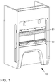
- FIG. 1 shows a perspective view of a machine tool 10.
- a machine tool 10 is used for the manufacture and processing of workpieces using tools.
- machine tools for example, metal or sheet metal processing machines, in particular bending machines or presses such as press brakes are considered here.
- a punch or an upper tool 20 presses a metal sheet into a die or a lower tool 30, which determines the bending angle.
- the reference numeral 30 may also denote a Unterwerkmaschineklemmung without tools. Most of the lower tool 30 has a V-shaped opening and the upper tool 20 has a wedge or a tip. Between the two tools 20 and 30, a sheet or often conical workpiece is placed. If the bending punch is lowered with a certain force, the workpiece is pressed into the opening of the lower tool 30 and bent to the required angle.
- FIG. 2 shows a side sectional view of a tool clamping device 200 in the open position, which serves for the clamping attachment of a tool, in this case an upper tool 20.
- the tool clamp 200 may also hold a lower tool.
- the tool 20 can be changed, that is, a tool 20 can be inserted or removed.
- the tool clamping device 200 comprises a longitudinal, in the representation of FIG. 2 into the image plane, basic body 202 whose length corresponds approximately to the width of the machine tool 10. On the main body 202, the tool clamping device 200 is mounted in the machine tool 10.
- a receiving space 204 for the tool 20 is provided in the main body 202.
- a spring 206 By means of a spring 206, the tool 20 can be secured against falling out even in the open state of the tool clamping device 200, accordingly, the tool 20 can be securely hung by means of the spring 206.
- a clamping wedge 208 which can engage in a corresponding recess of the tool 20, is fastened to a carrier plate 210.
- the support plate 210 is movable by a plurality of pistons 212, one of which is shown, in a clamping direction K. It is possible to attach the clamping wedge 208 directly, that is to say without a carrier plate 210, to the pistons 212.
- the spring-loaded clamping wedge 208 serves as a compensation element for tool tolerances and for clamping and pulling up the tool 20 to the main body 202.
- a Such clamping element may include the carrier plate 210 and the piston 212 in addition to the clamping wedge 208.
- the piston 212 is located in a guide 214.
- the guide 214 is formed as a round hole in the body and may, for example, comprise a running or guide bushing located in the hole.
- the cross section of the guide 214 corresponds to the cross section of the piston 212 and may have a different cross section instead of the round cross section shown here.
- a fluid space 216 running essentially perpendicular to the clamping direction K is provided with at least one opening 218 in the clamping direction K.
- the fluid space 216 serves to guide a fluid such as compressed air or hydraulic oil.
- the fluid space 216 extends in the longitudinal direction and a plurality of openings 218 are provided at a distance from one another, wherein a piston 212 is provided in the region of each opening 218.
- the opening 218 is sealingly closed with a pressurizable, flat actuator in the form of a membrane 220.
- the membrane 220 may be fabric reinforced and constructed in multiple layers.
- the membrane 220 is formed as a circular disk membrane. This means that a separate membrane 220 is provided or assigned for each opening 218 and thus for each piston 212.
- the opening 218 has a cross section or diameter which is slightly larger than a rear side 222 of the piston 212 opposite the clamping direction K. This means that the fluid space 216 also has an at least as large cross section. In this way, the membrane 220 can be uniformly charged with the fluid and moved. Alternatively, a smaller opening or a smaller fluid space can be provided, which is then aligned centrally with the piston 212.
- the membrane 220 is arranged with a mounting plate or ring 224 so in the clamping direction K spaced from the opening 218 that it can deflect in the clamping direction K and in the opposite direction. That is, the membrane 220 is in the open position shown here in the fluid space 216, so that the piston 212 is spaced from the tool 20 by a gap S. In order for the membrane 220 to move into the fluid space 216, it is spaced from the opening 218 and / or the fluid space 216 has a corresponding depth.
- the membrane 220 is installed in a solid housing so that it can swing into one or as shown in both directions. Thus, there are two separate spaces which are separated by the membrane 220. Thus, no fluid can flow through the membrane 220.
- the piston 212 with its backside 222 and the piston-side space with the mounting ring 224 are configured so that the membrane 220 can extend like sharp edges when expanded without hindrance, allowing for unlimited expansion and bursting of the diaphragm 220 at high pressures prevent.
- the diaphragm 220 swings out, pushes the piston 212 in the clamping direction K in front of it and can cleanly engage in the other space and on the piston 212.
- the stroke is terminated.
- the stroke is limited to the specifications of the membrane. Plate diaphragms usually reach strokes of 0.3 x effective diameter, so that a stroke of 9 mm can be achieved with an effective diameter of 30 mm.
- FIG. 3 11 shows the tool clamping device 200 in the closed position, that is, with fluid-filled fluid space 216, pressurized and bulging diaphragm 220, and piston 212 pushed out by the diaphragm. Accordingly, the tool 20 is interposed between the support plate 210 and a mating surface 226 under the engagement of wedge 208 fixed. The gap S is now closed, that is, its width is zero.
- the machine tool 10 is ready.
- the fluid space is depressurized, so that the piston 212 can move back and release the tool 20.
- This can be supported by one or more springs.
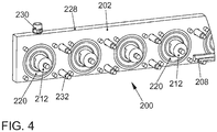
- FIG. 4 shows a schematic perspective view of a rear part 228 of the tool clamping device 200th
- all 60mm pistons 212 are arranged with a diameter of 20mm. These pistons 212 press the clamping wedge 208, which pulls the tool during the clamping process up, firmly against the opposite side of the groove in the body.
- the clamping wedge 208 acts like a spring and ensures a firm clamping of even narrow tools between the piston pressure points.
- the pistons 212 get their pressure force respectively through the Pressurized plate membrane 220. This is held by a sheet, which allows the curvature of the membrane 220 in the fluid space 216. At fluid pressure, the diaphragm 220 bulges in the other direction, that is, in the clamping direction, and presses against the piston 212.
- the rear part 228 serves to catch the opposing forces and for fluid guidance. In the intended piston diameter of, for example, 20 to 30 mm and a pressure of about 35 bar in this example per meter about 29000 N clamping force can be achieved.
- a pressure or fluid port 230 is disposed on the rear portion 228 and thus separated from the membranes 220, allowing easy replacement of both the membranes 220 and the fluid port 230.
- FIG. 5 shows a side sectional view of a second example of a tool clamping device 500 in the open position.
- a table base 502 carries a base 504 of the tool clamp 500.
- a longitudinal fluid space 506 is provided, for example, in the form of an elongated recess.
- an actuator is arranged, for example in the form of a membrane 508 covering the entire front side.
- the membrane 508 sealingly seals openings 510 of the fluid space 506.
- a plurality of clamping elements for example in the form of pistons 512, are arranged in front of the diaphragm 508.
- the pistons 512 are movably arranged in a guide 514 and, actuated by the diaphragm 508, are displaceable in the clamping direction K.
- the membrane 508 may cover all openings 510 of the fluid space 506. It can also be provided several modules that can be attached to each other. Then each module can have its own flat or ribbon membrane.
- the fluid space 506 is depressurized, so that the membrane 508 lies flat against the main body 504. Accordingly, the piston 512 is spaced from the tool 30 by a gap S.
- the tool clamping device 500 is shown here in conjunction with a lower tool 30, but it can also be used for an upper tool.
- FIG. 6 shows a side sectional view of the second example of the tool clamping device 500 in the closed position.
- the fluid chamber 506 is pressurized, so that the diaphragm 508 is bulged and thus the piston 512 presses in the clamping direction K until it rests against the tool 30, which forms a stop. As a result, the tool 30 is clamped between the piston 512 and a mating surface 516.
- a simple flat membrane can be installed here.
- Such a membrane allows strokes of 0.1x effective diameter, which, however, refers to the oscillation forward and backward. Since the membrane 508 is installed flat, only a swing in one direction is possible, so that halves the possible stroke. For example, assuming an effective diameter of 17mm results in a stroke of 0.85mm.
- FIG. 7 shows a schematic perspective view of the main body 504 of the second example of the tool clamping device 500th
- a pressure or fluid port 518 is disposed on the body 504 and thus separated from the diaphragms 508, allowing easy replacement of both the diaphragm 508 and the fluid port 518.
- the tool clamping device 500 used here as the lower tool clamping consists of two halves. A back side with the main body 504, in which the fluid guide 506 is located, and a front side, which receives the pressure piston 512.
- the front is sturdy because it not only clamps, but also rest the tools.
- a back pressure spring 520 is installed per piston.
- a pressure of 35 bar and a piston distance of 23 mm results in a force of about 30,000 N per meter.
- the advantages of the tool clamping device 500 are the simple design with few different components, the low system pressure of 35 bar and an interchangeability with existing systems, so that no table changes are necessary.
- the machine tool 10 in particular a press or a press brake, can, as described above, have a tool clamping device 200 for an upper tool 20 and a tool clamping device 500 for a lower tool 30.
- the two tool clamping devices 200 and 500 may be reversed, or two tool clamping devices 200 and 500 may be provided, respectively.
- a system for clamping tools may include a machine tool 10, at least one tool clamping device 200 or 500 and at least one tool 20 or 30, in particular a bending tool.
- the tool clamping devices 200 and 500 or the machine tool 10 presented here allow a simple and rapid fixation of a tool with a membrane acted upon by a fluid.
Landscapes
- Engineering & Computer Science (AREA)
- Mechanical Engineering (AREA)
- Machine Tool Units (AREA)
- Bending Of Plates, Rods, And Pipes (AREA)
- Mounting, Exchange, And Manufacturing Of Dies (AREA)
Priority Applications (3)
| Application Number | Priority Date | Filing Date | Title |
|---|---|---|---|
| EP17210466.3A EP3501681A1 (fr) | 2017-12-22 | 2017-12-22 | Dispositif de serrage d'outil pour machine-outil et machine-outil |
| DE212018000381.5U DE212018000381U1 (de) | 2017-12-22 | 2018-12-21 | Werkzeug-Klemmvorrichtung für eine Werkzeugmaschine und Werkzeugmaschine |
| PCT/EP2018/000590 WO2019120613A1 (fr) | 2017-12-22 | 2018-12-21 | Dispositif de serrage d'outil pour une machine-outil et machine-outil |
Applications Claiming Priority (1)
| Application Number | Priority Date | Filing Date | Title |
|---|---|---|---|
| EP17210466.3A EP3501681A1 (fr) | 2017-12-22 | 2017-12-22 | Dispositif de serrage d'outil pour machine-outil et machine-outil |
Publications (1)
| Publication Number | Publication Date |
|---|---|
| EP3501681A1 true EP3501681A1 (fr) | 2019-06-26 |
Family
ID=60813655
Family Applications (1)
| Application Number | Title | Priority Date | Filing Date |
|---|---|---|---|
| EP17210466.3A Withdrawn EP3501681A1 (fr) | 2017-12-22 | 2017-12-22 | Dispositif de serrage d'outil pour machine-outil et machine-outil |
Country Status (3)
| Country | Link |
|---|---|
| EP (1) | EP3501681A1 (fr) |
| DE (1) | DE212018000381U1 (fr) |
| WO (1) | WO2019120613A1 (fr) |
Cited By (1)
| Publication number | Priority date | Publication date | Assignee | Title |
|---|---|---|---|---|
| WO2022019754A1 (fr) * | 2020-07-24 | 2022-01-27 | Wila B.V. | Système de serrage pour presse plieuse ayant une cavité ou une chambre formée d'un seul tenant et presse plieuse comprenant un tel système de serrage |
Citations (7)
| Publication number | Priority date | Publication date | Assignee | Title |
|---|---|---|---|---|
| DD49135A (fr) * | ||||
| DE1897897U (de) * | 1961-12-23 | 1964-07-30 | Willi Hofmann | Spannvorrichtung zum festspannen von werkstuecken sowie fuer montagezwecke. |
| GB2057047A (en) * | 1979-08-01 | 1981-03-25 | Haemmerle Ag Maschf | Clamping device for fastening a tool to a tool holder |
| DE19752783A1 (de) * | 1997-11-28 | 1999-06-02 | Bayerische Motoren Werke Ag | Vorrichtung zum Spannen eines insbesondere Freiformflächen aufweisenden Werkstücks |
| US20040187552A1 (en) | 2003-03-31 | 2004-09-30 | Wila B.V. | Combination of a press brake clamping system and at least a press brake tool |
| CH700207A1 (de) * | 2009-01-06 | 2010-07-15 | Bystronic Laser Ag | Vorrichtung zum Fixieren von Werkzeugen in Werkzeugmaschinen. |
| US20110247389A1 (en) | 2008-11-11 | 2011-10-13 | Wila B.V. | Device for Clamping a Tool |
-
2017
- 2017-12-22 EP EP17210466.3A patent/EP3501681A1/fr not_active Withdrawn
-
2018
- 2018-12-21 WO PCT/EP2018/000590 patent/WO2019120613A1/fr active Application Filing
- 2018-12-21 DE DE212018000381.5U patent/DE212018000381U1/de active Active
Patent Citations (8)
| Publication number | Priority date | Publication date | Assignee | Title |
|---|---|---|---|---|
| DD49135A (fr) * | ||||
| DE1897897U (de) * | 1961-12-23 | 1964-07-30 | Willi Hofmann | Spannvorrichtung zum festspannen von werkstuecken sowie fuer montagezwecke. |
| GB2057047A (en) * | 1979-08-01 | 1981-03-25 | Haemmerle Ag Maschf | Clamping device for fastening a tool to a tool holder |
| DE19752783A1 (de) * | 1997-11-28 | 1999-06-02 | Bayerische Motoren Werke Ag | Vorrichtung zum Spannen eines insbesondere Freiformflächen aufweisenden Werkstücks |
| US20040187552A1 (en) | 2003-03-31 | 2004-09-30 | Wila B.V. | Combination of a press brake clamping system and at least a press brake tool |
| US6928852B2 (en) * | 2003-03-31 | 2005-08-16 | Wila B.V. | Combination of a press brake clamping system and at least a press brake tool |
| US20110247389A1 (en) | 2008-11-11 | 2011-10-13 | Wila B.V. | Device for Clamping a Tool |
| CH700207A1 (de) * | 2009-01-06 | 2010-07-15 | Bystronic Laser Ag | Vorrichtung zum Fixieren von Werkzeugen in Werkzeugmaschinen. |
Cited By (2)
| Publication number | Priority date | Publication date | Assignee | Title |
|---|---|---|---|---|
| WO2022019754A1 (fr) * | 2020-07-24 | 2022-01-27 | Wila B.V. | Système de serrage pour presse plieuse ayant une cavité ou une chambre formée d'un seul tenant et presse plieuse comprenant un tel système de serrage |
| NL2026130B1 (en) * | 2020-07-24 | 2022-03-28 | Wila Bv | Clamping system for a press brake having an integrally formed cavity or chamber and press brake comprising such a clamping system |
Also Published As
| Publication number | Publication date |
|---|---|
| WO2019120613A1 (fr) | 2019-06-27 |
| DE212018000381U1 (de) | 2020-07-27 |
Similar Documents
| Publication | Publication Date | Title |
|---|---|---|
| EP3248733B1 (fr) | Dispositif de serrage | |
| DE3142411C2 (fr) | ||
| DE2344416C2 (de) | Abkantpresse | |
| EP1055466B1 (fr) | Système d'entraínement hydraulique pour une machine d'assemblage | |
| DE2265348C3 (de) | Druckmittelbetriebener Servomotor | |
| DE4100206A1 (de) | Hydroelastische tiefzieheinrichtung | |
| DE2346028A1 (de) | Spannfutter | |
| WO2019120613A1 (fr) | Dispositif de serrage d'outil pour une machine-outil et machine-outil | |
| DE10113314C2 (de) | Fixiereinrichtung | |
| DE2704246A1 (de) | Pressenkopf mit mehreren stempeln zum wahlweisen abstreifen | |
| EP3302843B1 (fr) | Outil de pliage pour presse plieuse | |
| DE60015232T2 (de) | Vorrichtung zur Befestigung und Führung eines Lagers in einem Maschinenrahmen | |
| DE2946597C2 (de) | Einspannvorrichtung für biegsame Druckplatten | |
| WO2006131211A1 (fr) | Dispositif de liaison | |
| EP3501736B1 (fr) | Mâchoires de serrage pneumatique pour un étau | |
| DE10217973B4 (de) | Riemenbefestigungsmechanismus | |
| DE102017106356B4 (de) | Niederhaltervorrichtung für eine Ziehvorrichtung zur Herstellung von hohlzylindrischen Körpern | |
| DE10118534B4 (de) | Klemmsystem | |
| EP3302842B1 (fr) | Procédé de réglage d'une section de formage d'un outil de cintrage | |
| DE102015106084A1 (de) | Vorrichtung zur automatisierten Montage eines Schalenelements an einem Pleuelelement | |
| EP4063026B1 (fr) | Dispositif d'application | |
| DE10232772B3 (de) | Druckverteilungsring für eine Längsteilanlage | |
| CH640981A5 (en) | Appliance for working the connecting wires of electrical components | |
| EP4047757A1 (fr) | Dispositif et procédé d'usinage des contacts | |
| DE202023103546U1 (de) | Stanz- oder Nietwerkzeug |
Legal Events
| Date | Code | Title | Description |
|---|---|---|---|
| PUAI | Public reference made under article 153(3) epc to a published international application that has entered the european phase |
Free format text: ORIGINAL CODE: 0009012 |
|
| 17P | Request for examination filed |
Effective date: 20190122 |
|
| AK | Designated contracting states |
Kind code of ref document: A1 Designated state(s): AL AT BE BG CH CY CZ DE DK EE ES FI FR GB GR HR HU IE IS IT LI LT LU LV MC MK MT NL NO PL PT RO RS SE SI SK SM TR |
|
| AX | Request for extension of the european patent |
Extension state: BA ME |
|
| STAA | Information on the status of an ep patent application or granted ep patent |
Free format text: STATUS: THE APPLICATION IS DEEMED TO BE WITHDRAWN |
|
| 18D | Application deemed to be withdrawn |
Effective date: 20200103 |