EP3302843B1 - Bending tool for a press brake - Google Patents
Bending tool for a press brake Download PDFInfo
- Publication number
- EP3302843B1 EP3302843B1 EP16735976.9A EP16735976A EP3302843B1 EP 3302843 B1 EP3302843 B1 EP 3302843B1 EP 16735976 A EP16735976 A EP 16735976A EP 3302843 B1 EP3302843 B1 EP 3302843B1
- Authority
- EP
- European Patent Office
- Prior art keywords
- bending tool
- drive
- bending
- locking device
- section
- Prior art date
- Legal status (The legal status is an assumption and is not a legal conclusion. Google has not performed a legal analysis and makes no representation as to the accuracy of the status listed.)
- Active
Links
Images


Classifications
-
- B—PERFORMING OPERATIONS; TRANSPORTING
- B21—MECHANICAL METAL-WORKING WITHOUT ESSENTIALLY REMOVING MATERIAL; PUNCHING METAL
- B21D—WORKING OR PROCESSING OF SHEET METAL OR METAL TUBES, RODS OR PROFILES WITHOUT ESSENTIALLY REMOVING MATERIAL; PUNCHING METAL
- B21D5/00—Bending sheet metal along straight lines, e.g. to form simple curves
- B21D5/02—Bending sheet metal along straight lines, e.g. to form simple curves on press brakes without making use of clamping means
- B21D5/0209—Tools therefor
-
- B—PERFORMING OPERATIONS; TRANSPORTING
- B21—MECHANICAL METAL-WORKING WITHOUT ESSENTIALLY REMOVING MATERIAL; PUNCHING METAL
- B21D—WORKING OR PROCESSING OF SHEET METAL OR METAL TUBES, RODS OR PROFILES WITHOUT ESSENTIALLY REMOVING MATERIAL; PUNCHING METAL
- B21D37/00—Tools as parts of machines covered by this subclass
- B21D37/02—Die constructions enabling assembly of the die parts in different ways
-
- B—PERFORMING OPERATIONS; TRANSPORTING
- B21—MECHANICAL METAL-WORKING WITHOUT ESSENTIALLY REMOVING MATERIAL; PUNCHING METAL
- B21D—WORKING OR PROCESSING OF SHEET METAL OR METAL TUBES, RODS OR PROFILES WITHOUT ESSENTIALLY REMOVING MATERIAL; PUNCHING METAL
- B21D5/00—Bending sheet metal along straight lines, e.g. to form simple curves
- B21D5/02—Bending sheet metal along straight lines, e.g. to form simple curves on press brakes without making use of clamping means
- B21D5/0209—Tools therefor
- B21D5/0227—Length adjustment of the die
Definitions
- the invention relates to a bending tool for a bending press, comprising a preferably adjustable mold section for forming a workpiece.
- the DE3235775A1 discloses a lower tool for a press brake for folding sheet metal.
- On a lower part of a tool holder is arranged, in which a bending tool is used.
- the tool holder is designed as a tool holder split in the longitudinal direction of the handlebar. Both tool holder halves are adjustable transversely to the longitudinal direction Holml. In each tool holder half a replaceable Abkantwange can be used. The adjustment is made via an adjusting spindle.
- the EP0444169B1 discloses a tool for bending presses with a die, which have two half-matrices arranged on both sides of the bending plane. By a displacement of the half-matrices perpendicular to the pressing direction, the matrix shape can be broadened or narrowed.
- the WO0176784A1 discloses a tool with two mutually displaceable jaws for adjusting the die size. The shift takes place as in the two preceding documents in a direction perpendicular to the pressing direction.
- the US 5 022 248 A discloses an adjustable lower tool for a press brake with a hydraulic drive with which the mold sections can be moved to the desired position.
- the disadvantage of such constructions is that the change in the die width of a bending tool requires a separate operating mechanism that must be operated manually by an operator. Especially in a bending press the space for such manipulations is very narrow and visibility is severely limited, which has a complicated for the operator operation and often inaccurate setting result.
- the aim of the invention is to solve these problems and to simplify the adjustment, locking and / or the method of a bending tool. In addition to an increase in the adjustment or positioning accuracy, manipulations of the bending tool or on the bending tool to be automated. Adjustment, procedure and / or locking a bending tool should also be possible within a bending press, preferably even during a bending process.
- the drive is integrated in the bending tool or forms a unit with this.
- the drive comprises an energy supply interface, eg an electrical connection.
- the drive is an active drive, ie can only be activated when electrical energy, in particular, is supplied.
- the drive can be controlled either directly via the power supply interface or via a separate control input.
- the drive can be an actuating drive (eg in the sense of an actuator), an adjustment drive or a travel drive.
- the drive can be switchable or infinitely operable between (eg two) discrete (end) positions. It can be designed in particular as a motor (rotary or linear motor), solenoid, cylinder drive, pump drive, locking actuator and / or valve actuation.
- the bending tool can have at least two drives whose functionalities are different.
- the drive is accommodated in a bore extending in the bending tool, in particular in a block of solid material.
- the drive can be designed to save space, in particular as a miniature drive.
- the bending tool and the bending press are designed in particular for bending flat workpieces, in particular sheets.
- a preferred embodiment is characterized in that the locking device has a pressure medium channel which is divided by the actuatable valve, preferably by a pilot-operated check valve, into a first pressure medium region and a second pressure medium region, wherein the first pressure medium region adjoins the at least one Molded part is coupled.
- the pressure medium channel is filled with an incompressible pressure medium, preferably hydraulic oil.
- the valve can be of any type to decouple the pressure medium ranges from one another in terms of pressure. Examples would be a check valve (spring loaded or unloaded), a ball valve, slide valve, and the like. The valve could also be externally operable.
- Pressure medium channel is understood to mean any device which can accommodate pressure medium (even under pressure).
- the pressure medium channel may in particular be a pressure medium line, a pressure medium pipe and / or a cylinder in which e.g. an element with a piston surface is displaceable include.
- the pressure medium channel along its extension may have a constant or variable cross-section.
- the course of the pressure medium channel can be arbitrarily formed, in particular straight and curved sections.
- a mechanical locking device could also be used. This would represent a mechanical locking of the at least one molded part.
- An integrated drive could transfer the latch to the locked (or locked) and de-stressed (or released) states.
- a preferred embodiment is characterized in that the mold section has at least two movable mold parts which cooperate with the same locking device, in particular by a common pressure medium channel are coupled together.
- the adjustment and also provision of the moldings can be done synchronously. Also, only one locking device is required.
- a preferred embodiment is characterized in that the bending tool has a restoring device, in particular a return spring, for returning the at least one molded part.
- a preferred embodiment is characterized in that the restoring device comprises a force accumulator, in particular a spring, which can be acted upon by ei-ne adjusting movement of the at least one molded part.
- a force accumulator in particular a spring, which can be acted upon by ei-ne adjusting movement of the at least one molded part.
- a preferred embodiment is characterized in that the reset means cooperates with the blocking device, preferably being coupled to the second pressure medium region of the pressure medium channel. To reset only the locking device must be operated.
- a preferred embodiment is characterized in that a drive of the bending tool is an adjusting drive for adjusting the mold section, wherein the drive preferably cooperates with at least one movable relative to a holding portion of the bending tool molding of the mold section.
- the adjustment of the molding e.g., an increase in die width
- the adjustment accuracy can be increased.
- the adjustment can be carried out during the bending process on a workpiece. As a result, complex bending operations on a workpiece can be realized without having to change tools.
- a preferred embodiment is characterized in that a drive of the bending tool is a positioning drive for moving the bending tool in a tool holder or in a tool holder.
- a drive of the bending tool is a positioning drive for moving the bending tool in a tool holder or in a tool holder.
- a preferred embodiment is characterized in that the bending tool at least one movable by the drive drive part, in particular a wheel, a chain, a bead or a circulating belt having, wherein preferably at least a portion of the drive member is located on an outer side of the bending tool.
- the moving drive member acts on a stationary (driving) surface, e.g. the tool holder, together, whereby a movement of the bending tool is effected.
- a preferred embodiment is characterized in that the bending tool has at least one locking device for locking the bending tool on or in a tool holder and that a drive of the bending tool cooperates with the locking device, wherein the locking device by the drive in the locked state and / or in the dissolved state is transferable.
- the locking of the bending tool to the tool holder is automated.
- the drive encompassed by the bending tool ensures reliable operation and facilitates and shortens work processes associated with the bending process.
- a preferred embodiment is characterized in that the bending tool has an electrical, preferably rechargeable energy store (for example battery or rechargeable battery), which is connected to the drive.
- the energy store is preferably arranged in the interior of the bending tool and enables activation of the drive even in situations in which there is no external power supply. This can e.g. be the case when the bending tool is inserted in the tool holder of a bending press. If the tool has been returned to the tool magazine after a bending process, the energy storage device can be recharged there for the next use.
- a preferred embodiment is characterized in that the bending tool comprises a control device, by means of which the drive can be controlled. This enables targeted control in terms of time, direction and force.
- a preferred embodiment is characterized in that the bending tool has a preferably wireless control interface, which is connected to the control device.
- the drive of the bending tool can be reliably and in particular also controlled by radio.
- a preferred embodiment is characterized in that the drive is an electromagnetic drive, in particular a motor or an electromagnet, or a hydraulic drive, in particular a cylinder-piston unit or a pump drive.
- a preferred embodiment is characterized in that the bending tool has an electrical and / or electromagnetic interface, which is connected to the drive and / or with an electrical energy store, wherein preferably the interface is arranged on the holding portion of the bending tool.
- the drive is supplied with energy via the interface.
- a (preferably rechargeable) electrical energy store in particular a battery or a rechargeable battery, can also be connected between the interface and the drive. During use of the tool, the drive can draw energy from the energy storage.
- a preferred embodiment is characterized in that the bending tool has a holding portion for insertion of the bending tool in a tool holder of a bending press and that the mold portion comprises at least one movable relative to the holding portion molding.
- This embodiment of a bending tool allows an adjustment of the mold section by a drive integrated in the bending tool and / or by an external drive, in particular by a press drive and / or drive drive of a bending press.
- the mold portion with the movable mold part (s) and the holding portion may be formed on opposite sides of the bending tool, so that the adjusting operation of the mold portion is not affected by the holding or fixing of the bending tool by a tool holder.
- the mold section represents the workpiece-side section and the holding section represents the workpiece-facing section of the bending tool.
- the extent of the bending tool in a direction extending from the workpiece-side region of the mold section to the holding section is preferably variable. Such a (height) change goes hand in hand with an adjustment of the mold section.
- a preferred embodiment is characterized in that the mold section is adjustable by pressurizing the bending tool in a direction extending from the workpiece-side region of the mold section to the holding section. Such a pressurization can - as mentioned above - also be done by the press drive a bending press.
- a preferred embodiment is characterized in that a pressing direction is predetermined by the forming section of the bending tool (ie the shape of the forming section defines a pressing direction) and that the extension of the bending tool in the pressing direction is greater in a first position of the forming section than in a second position of the bending section forming section.
- the adjustment of the mold section is accompanied by a change in the height of the bending tool, i. the bending tool is compressible or fauxstauchbar.
- a change in shape of the mold portion e.g., change in die width
- the pressing direction is e.g. in the case of a die, defined by a direction perpendicular to the plane in which the die opening of the die is located. In the case of a punch, the pressing direction is dictated by the direction in which the punch points.
- a preferred embodiment is characterized in that the holding portion is formed on a block, wherein the at least one shaped part is movably mounted in or on the block, preferably linearly guided.
- the Formab-section with the movable molding (s) and the holding portion are preferably formed on opposite sides of the bending tool.
- the mold portion may be formed on the upper side of the bending tool and the holding portion on the underside of the bending tool.
- the (already mentioned) locking device can be integrated.
- a preferred embodiment is characterized in that the mold section of the bending tool forms a die whose die width is adjustable. This results in a variety of bending options with the same tool.
- the die is preferably elongate and has a substantially constant cross-section along its longitudinal extent.
- a preferred embodiment is characterized in that the mold portion of the bending tool comprises two linearly movable mold parts which form the die jaws of the die, wherein the directions of movement of the two mold parts are V-shaped.
- the adjustment can be carried out by a drive integrated in the bending tool or - alternatively - by a press drive of the bending press. In the latter case, pressurization in the pressing direction or transversely to the plane in which the die opening is located causes an enlargement of the die width.
- the distance between the workpiece-side end of the mold section and the holding section formed on the opposite side of the bending tool is thus variable.
- a compression of the bending tool is accompanied here by an increase in the Gesenkweite.
- a preferred embodiment is characterized in that the bending tool has a spacer, preferably in the form of a web, through which the die jaws spaced apart from each other. Such a spacer also forms a kind of guide through which the jaws are guided in a defined path.
- a preferred embodiment is characterized in that the at least one molded part is movable between two stop positions, wherein the one stop position corresponds to a fully extended position of the molded part and the other stop position of a fully retracted position of the molded part.
- the one stop position corresponds to a fully extended position of the molded part and the other stop position of a fully retracted position of the molded part.
- (in particular protruding) stops can be provided, which also prevent a molded part from falling off the rest of the bending tool.
- the aforementioned object is also achieved with a bending press with a tool holder and a bending tool according to the invention.
- a preferred embodiment is characterized in that the tool holder for supplying energy to the drive of a bending tool has an electrical or electromagnetic interface, wherein preferably the tool holder is in the form of a rail and the interface in the form of at least one along and / or running in the rail Contact strip is formed.
- the bending tool used in the tool holder can also be supplied with electrical energy during the bending process. In the case of a contact strip, such a supply can take place independently of the position of the bending tool in the rail.
- the object mentioned at the outset is also achieved with a method for manipulating a bending tool, wherein the manipulation of the bending tool is effected by a drive of the bending tool (that is, by a bending tool-specific drive).
- the method is performed during a bending process on a workpiece.
- a preferred embodiment relates to a method for adjusting a molding section of a bending tool in a bending press, which has a press drive.
- the adjustment of the molding section of the bending tool by the press drive and / or by a (integrated in the bending press) traversing drive in the bending press a relative movement between the bending tool with the mold section to be adjusted and an opposite bending tool in particular in a direction transverse to the pressing direction ( the bending press) causes.
- the adjustment of the mold section by the press drive and / or a travel drive integrated in the press brake is based on the idea of effecting the adjustment movement on the mold section by a relative movement of two opposing tools or tool holders.
- the press drive and / or the travel drive thus simultaneously act as an adjustment drive for the mold section. Therefore, no separate drive is required for the adjustment.
- the adjustment can be done automatically.
- a major advantage is that the adjustment can be done during the bending process on a workpiece. As a result, complex bending operations on a workpiece can be realized without having to change tools.
- the press drive is that drive that causes opposing tools to move toward each other and to bend a workpiece placed between them.
- the direction of the juxtaposition of opposing tools corresponds to the pressing direction of the bending press.
- the bending press can also have a travel drive in order to position the tools in particular transversely to the pressing direction.
- this travel drive can be used to adjust the mold section of a (used in the tool holder) bending tool.
- Corresponding the relative travel direction effected by the travel drive can (mechanically) act on a bending tool on the molding section of another bending tool and thereby move a movable molding.
- a preferred embodiment is characterized in that the adjustment of the mold section takes place in that by the press drive and / or by the drive mutually opposite tool holders of the bending press, preferably an upper tool holder and a lower tool holder, relative to each other, in particular towards each other to move, said Bending tool is held with the mold section to be adjusted by one of the tool holders and is applied via the opposite tool holder with pressure.
- the opposing tool holder or a bending tool or a workpiece inserted in the opposite tool holder abuts against the mold section to be adjusted.
- the bending tool to be adjusted is used here in the tool holder, i. it is already in the position required for the bending process.
- the mold section of this bending tool can now be adjusted without having to be removed from the tool holder.
- the adjustment takes place (directly or indirectly) by the relative movement of the opposite tool holder.
- a preferred embodiment is characterized in that the adjustment of the mold section of the bending tool is performed during a bending operation on a workpiece, wherein the workpiece during the Verstel-lens of the mold section is arranged in the bending press, preferably between the bending tool with the to be adjusted Form section and an opposite bending tool is clamped.
- this allows complex bending operations to be performed without the need to use (and change constantly) multiple tools with differently shaped mold sections.
- a preferred embodiment is characterized in that the Formab section of the bending tool forms a die and the adjustment of the mold section comprises an adjustment of the die width of the die.
- the shape of a workpiece, in particular on the bending edge, can be selectively influenced and varied.
- the die forming the bending tool is inserted in the lower tool holder.
- the Upper tool holder can now, preferably via an inserted upper tool, adjust the die.
- a preferred embodiment is characterized in that the bending tool has a holding section for inserting the bending tool into a tool holder of the bending press and that the mold section of the bending tool comprises at least one movable relative to the holding section mold part, wherein when adjusting the mold section by the press drive at least one molded part is preferably moved linearly relative to the holding section.
- the bending tool is fixed in the tool holder.
- the molded part remains - regardless of the fixation of the Garab-section through the tool holder - adjustable.
- the mold portion with the movable mold part (s) and the holding portion are preferably formed on opposite sides of the bending tool.
- the mold portion may be formed on the upper side of the bending tool and the holding portion on the underside of the bending tool.
- a preferred embodiment is characterized in that the adjustment of the mold section comprises a displacement of the at least one molded part and / or a pivoting of the at least one molded part and / or an inclination of the at least one molded part relative to the pressing direction.
- the adjustment of the mold section comprises a displacement of the at least one molded part and / or a pivoting of the at least one molded part and / or an inclination of the at least one molded part relative to the pressing direction.
- a preferred embodiment is characterized in that the bending tool comprises a cooperating with the mold section, preferably hydraulic locking device which secures the mold section against an adjustment in the locked state.
- the adjustment of the mold section can only be done with dissolved locking device. In the locked state ensures that the mold section does not change.
- the integration of such a blocking device on or in the bending tool represents a particularly preferred embodiment, because no separate measures must be taken to lock the mold section.
- a preferred embodiment is characterized in that the locking device is released that by the press drive opposing tool holders of the bending press are moved towards each other, wherein the bending tool is acted upon by the mold section to be adjusted with pressure, and that the locking device after reaching the desired position the mold section is transferred to the locked state.
- the actuation of the locking device is effected by a drive according to the invention encompassed by the bending tool.
- Fig. 1 and 2 show a bending press 10 with a lower tool holder 11 and an upper tool holder 12 and a press drive 13 for moving together the tool holders 11, 12 with the bending tools 1, 14 inserted therein. Between the tools 1, 14, a sheet-like workpiece is already positioned.
- the bending tool 1 has a holding section 5 for inserting the bending tool 1 into the tool holder 11 of the bending press 10 and a mold section 2 for forming the workpiece 15.
- the mold section 2 comprises two mold parts 3, 4 which are linearly movable relative to the holding section 5 and form the die jaws of a die.
- the holding portion 5 is formed on the underside of a block 6, wherein the mold parts 3, 4 are movably mounted in or on the block 6 (here: linearly guided).
- a comparison between the Fig. 1 and 2 shows that by an adjustment of the mold parts 3, 4, the die width of the die is adjustable.
- the degrees of freedom of movement of the two mold parts 3, 4 are V-shaped.
- the bending tool 1 comprises a spacer 21, preferably in the form of a web, through which the die jaws are spaced apart or guided.
- the mold parts 3, 4 are movable between two stop positions, wherein the one stop position of a fully extended position of the mold parts 3, 4 and the other stop position corresponds to a fully retracted position of the mold parts 3, 4.
- the stop position defining stop pin is in the Fig. 1 and 2 (not numbered) shown.
- the mold section 2 is adjustable by pressurizing the bending tool 1 in a direction extending from the workpiece-side region of the mold section 2 to the holding section 5.
- a pressing direction is defined (direction perpendicular to the plane in which the die opening is located). The extent (height) of the bending tool 1 in the pressing direction is greater in a first position of the molding section 2 ( Fig. 1 ) than in a second position of the mold section 2 ( Fig. 2 ).
- the adjustment of the mold section 2 can also be done by a positioning drive 26 of the bending press 10.
- the travel drive 26 effects a relative movement between the bending tool 1 with the mold section 2 to be adjusted and an opposite bending tool 14 in a direction transverse to the pressing direction 25.
- the adjustment of the mold section 2 can be effected in that by the press drive 13 and / or by the drive 26 opposing tool holders 11, 12 of the bending press 10, preferably an upper tool holder and a lower tool holder, relative to each other, in particular towards each other.
- the bending tool 1 is held with the mold section 2 to be adjusted by one of the tool holders 11 and pressurized via the opposite tool holder 12 with pressure.
- the opposing tool holder 12 or an inserted in the opposite tool holder 12 bending tool 14 (FIG. Fig. 8 ) or a workpiece 15 (FIG. Fig. 1 and 2 ) abut against the mold section 2 to be adjusted.
- the adjustment of the mold section 2 of the bending tool 1 can be performed during a bending operation on a workpiece 15.
- the workpiece 15 is arranged during the adjustment of the mold section 2 in the bending press 10, preferably clamped between the bending tools 1, 14.
- the adjustment of the mold section 2 may include a displacement and / or a pivoting of the at least one molded part 3, 4 and / or an inclination of the at least one molded part 3, 4 relative to the pressing direction 25.
- the molded parts 3, 4 each cooperate with transmission parts 23, 24, which have a piston surface on the side facing away from the respective molded part 3, 4 and are displaceable in a cylinder.
- the cylinders merge into a common pressure medium channel 17.
- the bending tool 1 comprises a cooperating with the mold section 2 (here: hydraulic) locking device 7, which secures the mold section 2 against an adjustment in the locked state.
- the locking device 7 is arranged in the interior of the bending tool 1.
- the locking device 7 comprises a drive 8, in particular an actuator, a motor, a cylinder or the like, by means of which the locking device 7 can be transferred into the locked state and / or into the released state.
- the locking device 7 is first released. Then 13 opposing tool holders 11, 12 of the bending press 10 are moved towards each other by the press drive. In this case, the bending tool 1 is subjected to the mold section to be adjusted 2 with pressure. After reaching the desired position of the mold section 2, the locking device 7 is transferred to the locked state.
- the blocking device 7 comprises a pressure medium channel 17, which is divided by an actuatable valve 16, preferably by a pilot-operated check valve, into a first pressure medium region 18 and a second pressure medium region 19.
- the first pressure medium region 18 is coupled to the molded parts 3, 4 via the transmission parts 23, 24.
- the two mold parts 3, 4 thus interact with the same locking device 7 in the illustrated embodiment.
- the locking device 7 is coupled via the second pressure medium region 19 with a return device 20, which causes a return of the molded parts 3, 4.
- the reset device 20 comprises a return spring and is designed as a force accumulator, which can be acted upon by an adjusting movement of the at least one molded part 3, 4.
- the mold parts 3, 4 can not be adjusted due to the incompressible pressure medium.
- the mold parts With the valve 16 open, the mold parts can be pushed down (e.g., by the press drive 13). In this case, the pressure medium flows into the cylinder of the return device 20 and acts there on the spring. Once the valve 16 is closed again, the mold parts remain locked.
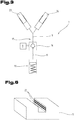
- Fig. 7 shows an embodiment of a locking mechanism 7, wherein the drive in the form of a (rotary) motor is formed. The rotational movement is converted into a linear movement of an actuating pin which opens the check valve 16.
- the drive 8 must bring the locking mechanism 7 only in the released state. In the locked state, the locking device 7 passes by itself, namely by the check valve sixteenth
- Fig. 4 and 5 show embodiments in which the locking device 7 are housed inside the bending tool 1 and the block 6.
- the pressure medium channel 17 may be formed by at least one bore.
- Fig. 4 is an out of the side wall of the bending tool 1 projecting actuator 26 can be seen, with which the valve position is adjustable from outside (here by a rotation).
- the valve 16 is integrally formed with the actuator 26.
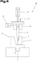
- the execution according to Fig. 5 shows a arranged in the interior of the bending tool 1 and the block 6 drive 8, which is designed here as a valve drive. Also visible is an electrical interface 9 which is connected to the drive 8.
- the interface 9 is arranged on the holding section 5 of the bending tool 1.
- the 6 shows a corresponding tool holder 11, which has an electrical interface 22 for supplying energy to the bending tool 1.
- the tool holder 11, 12 has the shape of a rail.
- the interface 22 is designed in the form of at least one contact strip extending along or in the rail.
- electrical interfaces 9, 22, electromagnetic (ie inductive) interfaces could also be used.
- the bending tool 1 at least one drive 8, 28, 34, 38. This is preferably arranged in the interior of the bending tool 1.
- the ability to link the locking device 7 with an integrated, ie bending tools own drive has already been described in detail.
- Such a drive 28 cooperates with at least one movable relative to a holding portion 5 of the bending tool 1 molded part 3, 4 of the mold section 2.
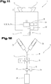
- the drive is designed as a drive 28 of a pump 27 (with two delivery directions).
- the pump 27 delivers the pressure medium and pushes (or 'pulls') so that the transmission parts 23, 24, whereby an adjustment of at least one molded part 3 is effected.
- Fig. 12 the one pump connection to the valve 16 and the other pump connection to a pressure medium reservoir 29 is connected.
- Fig. 13 also the possibility of an application to a stamp-like bending tool. 1
- the embodiment according to Fig. 9 shows a bending tool 1 with a traversing drive 38 for moving the bending tool 1 in a tool holder 11 or in a tool holder 11.
- the bending tool 1 comprises at least one movable by the drive 38 driving part 37, in particular a wheel, a chain, a bead or a circulating band.
- the drive 38 driving part 37 in particular a wheel, a chain, a bead or a circulating band.
- at least a portion of the drive part 37 is located on an outer side of the bending tool 1.
- the embodiment according to Fig. 10 shows a bending tool with a locking device 35 for locking the bending tool 1 on or in a tool holder 11.
- An integrated drive 34 of the bending tool 1 cooperates with the locking device 35 (here via a pressure medium line 36).
- the locking device 35 can be transferred by the drive 34 in the locked state and / or in the released state.
- the drive 8, 28, 34, 38 may be, for example, an electromagnetic drive, in particular a motor or an electromagnet, or a hydraulic drive, in particular a cylinder-piston unit or a pump drive.
- the bending tool 1 may have an electrical, preferably rechargeable energy storage 32, which is connected to the drive 8, 28, 34, 38.
- the bending tool 1 may have a control device 30, by means of which the drive 8, 28, 34, 38 can be actuated.
- a preferably wireless control interface 31 connected to the controller 30 may be provided to communicate external control commands.
- an electrical (or inductive) interface 9 which is connected to the drive 8 and to the electrical energy store 32.
- Such a bending tool 1 can with a tool holder 11 according to Fig. 6 or Fig. 8 used to power the drive, in particular to energize.
Description
Die Erfindung betrifft ein Biegewerkzeug für eine Biegepresse, umfassend einen vorzugsweise verstellbaren Formabschnitt zum Formen eines Werkstückes.
Die
Die
Die
The
The
The
Die
Der Nachteil derartiger Konstruktionen besteht darin, dass die Veränderung der Gesenkweite eines Biegewerkzeuges einen gesonderten Betätigungsmechanismus erfordert, der von einer Bedienperson händisch bedient werden muss. Gerade in einer Biegepresse ist der Raum für derartige Manipulationen sehr eng und ist die Sicht stark eingeschränkt, was eine für die Bedienperson aufwendige Betätigung und oftmals ungenaue Einstellung zur Folge hat.
Das Ziel der Erfindung besteht darin, diese Probleme zu lösen und die Verstellung, Arretierung und/oder das Verfahren eines Biegewerkzeuges zu vereinfachen. Neben einer Erhöhung der Verstell- oder Positioniergenauigkeit, sollen Manipulationen des Biegewerkzeuges bzw. an dem Biegewerkzeug automatisierbar werden. Verstellen, Verfahren und/oder Arretieren eines Biegewerkzeuges sollen auch innerhalb einer Biegepresse, bevorzugt sogar während eines Biegevorganges, möglich sein.The disadvantage of such constructions is that the change in the die width of a bending tool requires a separate operating mechanism that must be operated manually by an operator. Especially in a bending press the space for such manipulations is very narrow and visibility is severely limited, which has a complicated for the operator operation and often inaccurate setting result.
The aim of the invention is to solve these problems and to simplify the adjustment, locking and / or the method of a bending tool. In addition to an increase in the adjustment or positioning accuracy, manipulations of the bending tool or on the bending tool to be automated. Adjustment, procedure and / or locking a bending tool should also be possible within a bending press, preferably even during a bending process.
Dieses Ziel wird mit einem eingangs genannten Biegewerkzeug mit den Merkmalen des Anspruchs 1 gelöst. Der Antrieb ist im Biegewerkzeug integriert bzw. bildet mit diesem eine Einheit. Durch die Integration eines Antriebes in einem Biegewerkzeug können die Funktionalitäten des Biegewerkzeuges erweitert werden. Manipulationen des Biegewerkzeuges müssen nicht länger händisch oder durch externe Betätigung erfolgen. Die durch die Integration eines Antriebes einhergehende Automatisierung führt zu einer signifikanten Vereinfachung und Verkürzung von Arbeitsprozessen.
Der Antrieb umfasst eine Energieversorgungsschnittstelle, z.B. einen elektrischen Anschluss. Der Antrieb ist insbesondere ein aktiver Antrieb, d.h. erst bei Zufuhr von insbesondere elektrischer Energie aktivierbar. Das Ansteuern des Antriebes kann entweder direkt über die Energieversorgungsschnittstelle oder über einen gesonderten Steuereingang erfolgen.
Der Antrieb kann - je nach seiner Funktion im Biegewerkzeug - ein Stell-Antrieb (z.B. im Sinne eines Aktuators), ein Verstell-Antrieb oder ein Verfahr-Antrieb sein. Der Antrieb kann zwischen (z.B. zwei) diskreten (End-)Stellungen schaltbar oder stufenlos betätigbar sein. Er kann insbesondere als Motor (Dreh- oder Linearmotor), Hubmagnet, Zylinderantrieb, Pumpenantrieb, Arretierbetätigung und/oder Ventilbetätigung ausgebildet sein. Das Biegewerkzeug kann zumindest zwei Antriebe aufweisen, deren Funktionalitäten unterschiedlich sind.
Bevorzugt ist der Antrieb in einer sich im Biegewerkzeug, insbesondere in einem Block aus massivem Material, erstreckenden Bohrung untergebracht. Der Antrieb kann entsprechend raumsparend ausgebildet sein, insbesondere als Miniaturantrieb.
Das Biegewerkzeug und die Biegepresse sind insbesondere zum Biegen von flächigen Werkstücken, insbesondere Blechen ausgebildet.This object is achieved with an initially mentioned bending tool having the features of
The drive comprises an energy supply interface, eg an electrical connection. In particular, the drive is an active drive, ie can only be activated when electrical energy, in particular, is supplied. The drive can be controlled either directly via the power supply interface or via a separate control input.
Depending on its function in the bending tool, the drive can be an actuating drive (eg in the sense of an actuator), an adjustment drive or a travel drive. The drive can be switchable or infinitely operable between (eg two) discrete (end) positions. It can be designed in particular as a motor (rotary or linear motor), solenoid, cylinder drive, pump drive, locking actuator and / or valve actuation. The bending tool can have at least two drives whose functionalities are different.
Preferably, the drive is accommodated in a bore extending in the bending tool, in particular in a block of solid material. The drive can be designed to save space, in particular as a miniature drive.
The bending tool and the bending press are designed in particular for bending flat workpieces, in particular sheets.
Erfindungsgemäß zeichnet sich das Biegewerkzeug dadurch aus, dass
- der Formabschnitt verstellbar ist,
- das Biegewerkzeug eine mit dem Formabschnitt zusammenwirkende, vorzugsweise hydraulische Sperreinrichtung umfasst, die im gesperrten Zustand den Formabschnitt gegen Verstellung sichert, und
- ein Antrieb des Biegewerkzeuges mit der Sperreinrichtung zusammenwirkt, wobei die Sperreinrichtung durch den Antrieb in den gesperrten Zustand und/oder in den gelösten Zustand überführbar ist.
Durch den Antrieb des Biegewerkzeuges (insbesondere einen Aktuator, einen Motor, einen Zylinder oder dgl.) ist die Sperreinrichtung in den gesperrten Zustand und/oder in den gelösten Zustand überführbar. Das Lösen und/oder Sperren kann durch Aktivierung des in dem Biegewerkzeug integrierten Antriebs daher automatisch, vorzugsweise durch eine Steuerung erfolgen. Das Hantieren einer Bedienperson im ohnedies sehr engen (Gefahren-)Bereich ist hier nicht erforderlich. Bevorzugt wirkt der Antrieb (als Ventilbetätigung) mit einem betätigbaren (sperr- bzw. entsperrbaren) Ventil der Sperreinrichtung zusammen.
Die Sperreinrichtung ist vorzugsweise im Inneren des Biegewerkzeuges angeordnet. Die Integration der Sperreinrichtung im Inneren des Biegewerkzeuges ermöglicht die Konstruktion kompakter und leicht handhabbarer Werkzeuge. Im Inneren des Biegewerkzeuges ist die Sperreinrichtung vor äußeren Einflüssen geschützt. In unmittelbarer Nähe des Formabschnittes kann sie auch sehr platzsparend ausgebildet sein.According to the invention, the bending tool is characterized in that
- the mold section is adjustable,
- the bending tool comprises a cooperating with the mold section, preferably hydraulic locking device which secures the mold section against adjustment in the locked state, and
- a drive of the bending tool cooperates with the locking device, wherein the locking device can be converted by the drive in the locked state and / or in the released state.
By driving the bending tool (in particular an actuator, an engine, a cylinder or the like.) Is the locking device in the locked state and / or in the dissolved state can be transferred. The release and / or locking can therefore take place automatically by activation of the drive integrated in the bending tool, preferably by a controller. The handling of an operator in anyway very narrow (danger) area is not required here. Preferably, the drive (as a valve actuation) cooperates with an actuatable (lockable or unlockable) valve of the locking device.
The locking device is preferably arranged in the interior of the bending tool. The integration of the locking device inside the bending tool allows the construction of compact and easy-to-handle tools. Inside the bending tool, the locking device is protected from external influences. In the immediate vicinity of the mold section, it can also be designed to save space.
Eine bevorzugte Ausführungsform zeichnet sich dadurch aus, dass die Sperrein-richtung einen Druckmittelkanal aufweist, der durch das betätigbare Ventil, vorzugsweise durch ein entsperrbares Rückschlagventil, in einen ersten Druckmittel-bereich und einen zweiten Druckmittelbereich geteilt ist, wobei der erste Druckmittelbereich an den zumindest einen Formteil gekoppelt ist. Der Druckmittelkanal ist mit einem inkompressiblen Druckmittel gefüllt, vorzugsweise Hydrauliköl. Durch diese Maßnahme kann eine stufenlose Verstellung bzw. eine Arretierung des Formabschnittes in jeder beliebigen Stellung erfolgen. Bei geschlossenem Ventil bleibt der Formabschnitt aufgrund des inkompressiblen Druckmittels in dem ersten Druckmittelbe-reich arretiert. Bei geöffnetem Ventil kann das Druckmittel vom ersten Druckmittelbereich in den zweiten Druckmittelbereich strömen, wobei nun auch der Formabschnitt verstellbar ist. Das besagte Ventil ist durch den oben erwähnten Antrieb des Biegewerkzeuges betätigbar.A preferred embodiment is characterized in that the locking device has a pressure medium channel which is divided by the actuatable valve, preferably by a pilot-operated check valve, into a first pressure medium region and a second pressure medium region, wherein the first pressure medium region adjoins the at least one Molded part is coupled. The pressure medium channel is filled with an incompressible pressure medium, preferably hydraulic oil. By this measure, a continuous adjustment or locking of the mold section can be done in any position. When the valve is closed, the mold section remains locked in the first pressure medium region due to the incompressible pressure medium. When the valve is open, the pressure medium can flow from the first pressure medium area into the second pressure medium area, wherein now also the shape section is adjustable. The said valve is operable by the above-mentioned drive of the bending tool.
Das Ventil kann jeglicher Art sein, um die Druckmittelbereiche druckmäßig voneinander zu entkoppeln. Beispiele wären ein Rückschlagventil (federbelastet oder unbelastet), ein Kugelhahnventil, Schiebeventil, und dgl. Das Ventil könnte auch von extern betätigbar sein.The valve can be of any type to decouple the pressure medium ranges from one another in terms of pressure. Examples would be a check valve (spring loaded or unloaded), a ball valve, slide valve, and the like. The valve could also be externally operable.
Unter "Druckmittelkanal" wird jede Einrichtung verstanden, die Druckmittel (auch unter Druck) beherbergen kann. Der Druckmittelkanal kann insbesondere eine Druckmittelleitung, ein Druckmittelrohr und/oder einen Zylinder, in dem z.B. ein Element mit einer Kolbenfläche verschiebbar ist, umfassen. Außerdem kann der Druckmittelkanal entlang seiner Erstreckung einen konstanten oder veränderlichen Querschnitt aufweisen. Auch der Verlauf des Druckmittelkanals kann beliebig aus-gebildet sein, insbesondere geradlinige und gebogene Abschnitte aufweisen."Pressure medium channel" is understood to mean any device which can accommodate pressure medium (even under pressure). The pressure medium channel may in particular be a pressure medium line, a pressure medium pipe and / or a cylinder in which e.g. an element with a piston surface is displaceable include. In addition, the pressure medium channel along its extension may have a constant or variable cross-section. Also, the course of the pressure medium channel can be arbitrarily formed, in particular straight and curved sections.
Anstelle (oder zusätzlich zu) einer hydraulischen Sperreinrichtung könnte auch eine mechanische Sperreinrichtung verwendet werden. Diese würde eine mechanische Verriegelung des zumindest einen Formteiles darstellen. Ein integrierter Antrieb könnte die Verriegelung in den verriegelten (bzw. gesperrten) und entrigelten (bzw. gelösten) Zustand überführen.Instead of (or in addition to) a hydraulic locking device, a mechanical locking device could also be used. This would represent a mechanical locking of the at least one molded part. An integrated drive could transfer the latch to the locked (or locked) and de-stressed (or released) states.
Eine bevorzugte Ausführungsform zeichnet sich dadurch aus, dass der Formabschnitt zumindest zwei bewegbare Formteile aufweist, die mit derselben Sperreinrichtung zusammenwirken, insbesondere durch einen gemeinsamen Druckmittel-kanal miteinander gekoppelt sind.A preferred embodiment is characterized in that the mold section has at least two movable mold parts which cooperate with the same locking device, in particular by a common pressure medium channel are coupled together.
Die Verstellung und auch Rückstellung der Formteile kann dadurch synchron erfolgen. Auch ist nur eine Sperreinrichtung erforderlich.The adjustment and also provision of the moldings can be done synchronously. Also, only one locking device is required.
Eine bevorzugte Ausführungsform zeichnet sich dadurch aus, dass das Biege-werkzeug eine Rückstelleinrichtung, insbesondere eine Rückstellfeder, zur Rück-stellung des zumindest einen Formteiles aufweist. Durch diese Maßnahme kann der (zuvor verstellte) Formteil bereits innerhalb der Biegepresse und auch in eigesetztem Zustand des Biegewerkzeuges in seine ursprüngliche Position verbracht werden. Der Formteil kann somit in entgegengesetzte Richtungen bewegt werden.A preferred embodiment is characterized in that the bending tool has a restoring device, in particular a return spring, for returning the at least one molded part. By this measure, the (previously adjusted) molded part can already be spent within the bending press and in eigesetztem state of the bending tool in its original position. The molded part can thus be moved in opposite directions.
Eine bevorzugte Ausführungsform zeichnet sich dadurch aus, dass die Rückstelleinrichtung einen Kraftspeicher, insbesondere eine Feder, umfasst, der durch ei-ne Verstellbewegung des zumindest einen Formteiles beaufschlagbar ist. Diese besonders elegante Lösung erfordert für die Rückstellbewegung keinen aktiven Antrieb.A preferred embodiment is characterized in that the restoring device comprises a force accumulator, in particular a spring, which can be acted upon by ei-ne adjusting movement of the at least one molded part. This particularly elegant solution requires no active drive for the return movement.
Eine bevorzugte Ausführungsform zeichnet sich dadurch aus, dass die Rückstel-leinrichtung mit der Sperreinrichtung zusammenwirkt, vorzugsweise an den zwei-ten Druckmittelbereich des Druckmittelkanals gekoppelt ist. Zur Rückstellung muss lediglich die Sperreinrichtung betätigt werden.A preferred embodiment is characterized in that the reset means cooperates with the blocking device, preferably being coupled to the second pressure medium region of the pressure medium channel. To reset only the locking device must be operated.
Eine bevorzugte Ausführungsform zeichnet sich dadurch aus, dass ein Antrieb des Biegewerkzeuges ein Verstell-Antrieb zum Verstellen des Formabschnittes ist, wobei der Antrieb vorzugsweise mit zumindest einem relativ zu einem Halteabschnitt des Biegewerkzeuges bewegbaren Formteil des Formabschnittes zusammenwirkt. In dieser Ausführungsform kann die Verstellung des Formteiles (z.B. eine Vergrößerung der Gesenkweite) automatisiert werden. Ein großer Vorteil besteht darin, dass die Verstellgenauigkeit erhöht werden kann. Außerdem kann der Verstellvorgang während des Biegevorganges an einem Werkstück erfolgen. Dadurch können komplexe Biegevorgänge an einem Werkstück realisiert werden, ohne Werkzeuge wechseln zu müssen.A preferred embodiment is characterized in that a drive of the bending tool is an adjusting drive for adjusting the mold section, wherein the drive preferably cooperates with at least one movable relative to a holding portion of the bending tool molding of the mold section. In this embodiment, the adjustment of the molding (e.g., an increase in die width) can be automated. A big advantage is that the adjustment accuracy can be increased. In addition, the adjustment can be carried out during the bending process on a workpiece. As a result, complex bending operations on a workpiece can be realized without having to change tools.
Eine bevorzugte Ausführungsform zeichnet sich dadurch aus, dass ein Antrieb des Biegewerkzeuges ein Verfahr-Antrieb zum Verfahren des Biegewerkzeuges in einer Werkzeughalterung oder in eine Werkzeughalterung ist. Durch diese Maßnahme wird das Biegewerkzeug selbstfahrend. Eine externe Verfahreinrichtung ist daher nicht mehr unbedingt erforderlich. Diese Maßnahme ermöglicht ein automatisches und genaues Positionieren des Biegewerkzeuges durch einen werkzeugeigenen Antrieb.A preferred embodiment is characterized in that a drive of the bending tool is a positioning drive for moving the bending tool in a tool holder or in a tool holder. By this measure, the bending tool self-propelled. An external moving device is therefore no longer absolutely necessary. This measure allows an automatic and accurate positioning of the bending tool by a tool drive.
Eine bevorzugte Ausführungsform zeichnet sich dadurch aus, dass das Biegewerkzeug zumindest ein durch den Antrieb bewegbares Antriebsteil, insbesondere ein Rad, eine Kette, eine Raupe oder ein umlaufendes Band, aufweist, wobei sich vorzugsweise zumindest ein Abschnitt des Antriebsteils an einer Außenseite des Biegewerkzeuges befindet. Das sich bewegende Antriebsteil wirkt mit einer stationären (Fahr-)Fläche, z.B. der Werkzeughalterung, zusammen, wodurch eine Bewegung des Biegewerkzeuges bewirkt wird.A preferred embodiment is characterized in that the bending tool at least one movable by the drive drive part, in particular a wheel, a chain, a bead or a circulating belt having, wherein preferably at least a portion of the drive member is located on an outer side of the bending tool. The moving drive member acts on a stationary (driving) surface, e.g. the tool holder, together, whereby a movement of the bending tool is effected.
Eine bevorzugte Ausführungsform zeichnet sich dadurch aus, dass das Biegewerkzeug zumindest eine Arretiereinrichtung zum Arretieren des Biegewerkzeuges an oder in einer Werkzeughalterung aufweist und dass ein Antrieb des Biegewerkzeuges mit der Arretiereinrichtung zusammenwirkt, wobei die Arretiereinrichtung durch den Antrieb in den arretierten Zustand und/oder in den gelösten Zustand überführbar ist. In dieser Ausführungsform wird das Verriegeln des Biegewerkzeuges an der Werkzeughalterung automatisiert. Der vom Biegewerkzeug umfasste Antrieb gewährleistet eine zuverlässige Betätigung und erleichtert und verkürzt mit dem Biegevorgang zusammenhängende Arbeitsprozesse.A preferred embodiment is characterized in that the bending tool has at least one locking device for locking the bending tool on or in a tool holder and that a drive of the bending tool cooperates with the locking device, wherein the locking device by the drive in the locked state and / or in the dissolved state is transferable. In this embodiment, the locking of the bending tool to the tool holder is automated. The drive encompassed by the bending tool ensures reliable operation and facilitates and shortens work processes associated with the bending process.
Eine bevorzugte Ausführungsform zeichnet sich dadurch aus, dass das Biegewerkzeug einen elektrischen, vorzugsweise wiederaufladbaren Energiespeicher (z.B. Batterie oder Akku) aufweist, der mit dem Antrieb verbunden ist. Der Energiespeicher ist vorzugsweise im Inneren des Biegewerkzeuges angeordnet und ermöglicht eine Aktivierung des Antriebes auch in Situationen, in denen keine externe Energieversorgung vorhanden ist. Dies kann z.B. der Fall sein, wenn das Biegewerkzeug in der Werkzeughalterung einer Biegepresse eingesetzt ist. Wenn das Werkzeug nach einem Biegevorgang wieder in das Werkzeugmagazin verbracht wurde, kann der Energiespeicher dort für den nächsten Einsatz wieder aufgeladen werden.A preferred embodiment is characterized in that the bending tool has an electrical, preferably rechargeable energy store (for example battery or rechargeable battery), which is connected to the drive. The energy store is preferably arranged in the interior of the bending tool and enables activation of the drive even in situations in which there is no external power supply. This can e.g. be the case when the bending tool is inserted in the tool holder of a bending press. If the tool has been returned to the tool magazine after a bending process, the energy storage device can be recharged there for the next use.
Eine bevorzugte Ausführungsform zeichnet sich dadurch aus, dass das Biegewerkzeug eine Steuereinrichtung umfasst, durch die der Antrieb ansteuerbar ist. Dies ermöglicht eine gezielte Ansteuerung in zeitlicher, richtungsbezogener und kraftbezogener Hinsicht.A preferred embodiment is characterized in that the bending tool comprises a control device, by means of which the drive can be controlled. This enables targeted control in terms of time, direction and force.
Eine bevorzugte Ausführungsform zeichnet sich dadurch aus, dass das Biegewerkzeug eine vorzugsweise drahtlose Steuerschnittstelle aufweist, die mit der Steuereinrichtung verbunden ist. Dadurch kann der Antrieb des Biegewerkzeuges zuverlässig und insbesondere auch per Funk angesteuert werden.A preferred embodiment is characterized in that the bending tool has a preferably wireless control interface, which is connected to the control device. As a result, the drive of the bending tool can be reliably and in particular also controlled by radio.
Eine bevorzugte Ausführungsform zeichnet sich dadurch aus, dass der Antrieb ein elektromagnetischer Antrieb, insbesondere ein Motor oder ein Elektromagnet, oder ein hydraulischer Antrieb, insbesondere eine Zylinder-Kolben-Einheit oder ein Pumpenantrieb, ist.A preferred embodiment is characterized in that the drive is an electromagnetic drive, in particular a motor or an electromagnet, or a hydraulic drive, in particular a cylinder-piston unit or a pump drive.
Eine bevorzugte Ausführungsform zeichnet sich dadurch aus, dass das Biegewerkzeug eine elektrische und/oder elektromagnetische Schnittstelle aufweist, die mit dem Antrieb und/oder mit einem elektrischen Energiespeicher verbunden ist, wobei vorzugsweise die Schnittstelle an dem Halteabschnitt des Biegewerkzeuges angeordnet ist. Über die Schnittstelle wird der Antrieb mit Energie versorgt. Zwischen Schnittstelle und Antrieb kann auch ein (vorzugsweise wiederaufladbarer) elektrischer Energiespeicher, insbesondere eine Batterie oder ein Akku, geschaltet sein. Während des Einsatzes des Werkzeuges kann der Antrieb Energie aus dem Energiespeicher beziehen.A preferred embodiment is characterized in that the bending tool has an electrical and / or electromagnetic interface, which is connected to the drive and / or with an electrical energy store, wherein preferably the interface is arranged on the holding portion of the bending tool. The drive is supplied with energy via the interface. A (preferably rechargeable) electrical energy store, in particular a battery or a rechargeable battery, can also be connected between the interface and the drive. During use of the tool, the drive can draw energy from the energy storage.
Eine bevorzugte Ausführungsform zeichnet sich dadurch aus, dass das Biegewerkzeug einen Halteabschnitt zum Einsetzen des Biegewerkzeuges in eine Werkzeughalterung einer Biegepresse aufweist und dass der Formabschnitt zumindest einen relativ zum Halteabschnitt bewegbaren Formteil umfasst.A preferred embodiment is characterized in that the bending tool has a holding portion for insertion of the bending tool in a tool holder of a bending press and that the mold portion comprises at least one movable relative to the holding portion molding.
Diese Ausgestaltung eines Biegewerkzeuges ermöglicht eine Verstellung des Formabschnittes durch einen in dem Biegewerkzeug integrierten Antrieb und/oder durch einen externen Antrieb, insbesondere durch einen Pressantrieb und/oder Verfahrantrieb einer Biegepresse. Der Formabschnitt mit dem/den bewegbaren Formteil(en) und der Halteabschnitt können an gegenüberliegenden Seiten des Biegewerkzeuges ausgebildet sein, sodass der Verstellvorgang des Formabschnittes durch das Halten bzw. Fixieren des Biegewerkzeuges durch eine Werkzeughalterung nicht beeinträchtigt ist. Der Formabschnitt stellt den werkstückseitigen Abschnitt und der Halteabschnitt den werkstückabgewandten Abschnitt des Biegewerkzeuges dar.This embodiment of a bending tool allows an adjustment of the mold section by a drive integrated in the bending tool and / or by an external drive, in particular by a press drive and / or drive drive of a bending press. The mold portion with the movable mold part (s) and the holding portion may be formed on opposite sides of the bending tool, so that the adjusting operation of the mold portion is not affected by the holding or fixing of the bending tool by a tool holder. The mold section represents the workpiece-side section and the holding section represents the workpiece-facing section of the bending tool.
Die Erstreckung des Biegewerkzeuges in einer vom werkstückseitigen Bereich des Formabschnittes zum Halteabschnitt verlaufenden Richtung ist vorzugsweise veränderlich. Eine solche (Höhen-)Veränderung geht hier mit einer Verstellung des Formabschnittes einher.The extent of the bending tool in a direction extending from the workpiece-side region of the mold section to the holding section is preferably variable. Such a (height) change goes hand in hand with an adjustment of the mold section.
Eine bevorzugte Ausführungsform zeichnet sich dadurch aus, dass der Formabschnitt durch Druckbeaufschlagung des Biegewerkzeuges in einer vom werkstückseitigen Bereich des Formabschnittes zum Halteabschnitt verlaufenden Richtung verstellbar ist. Eine solche Druckbeaufschlagung kann - wie oben erwähnt - auch durch den Pressantrieb einer Biegepresse erfolgen.A preferred embodiment is characterized in that the mold section is adjustable by pressurizing the bending tool in a direction extending from the workpiece-side region of the mold section to the holding section. Such a pressurization can - as mentioned above - also be done by the press drive a bending press.
Eine bevorzugte Ausführungsform zeichnet sich dadurch aus, dass durch den Formabschnitt des Biegewerkzeuges eine Pressrichtung vorgegeben ist (d.h. die Form des Formabschnittes definiert eine Pressrichtung) und dass die Erstreckung des Biegewerkzeuges in Pressrichtung in einer ersten Stellung des Formabschnittes größer ist als in einer zweiten Stellung des Formabschnittes. In dieser Ausführungsform geht die Verstellung des Formabschnittes mit einer Änderung der Höhe des Biegewerkzeuges einher, d.h. das Biegewerkzeug ist zusammendrückbar bzw. zusammenstauchbar. Auch eine Formänderung des Formabschnittes (z.B. Veränderung der Gesenkweite) kann mit dieser Höhenverstellbarkeit des Biegewerkzeuges verknüpft sein. Die Pressrichtung wird z.B. im Falle einer Matrize durch eine Richtung definiert, die senkrecht auf die Ebene steht, in der die Gesenköffnung der Matrize liegt. Im Falle eines Stempels ist die Pressrichtung durch jene Richtung vorgegeben, in die der Stempel weist.A preferred embodiment is characterized in that a pressing direction is predetermined by the forming section of the bending tool (ie the shape of the forming section defines a pressing direction) and that the extension of the bending tool in the pressing direction is greater in a first position of the forming section than in a second position of the bending section forming section. In this embodiment, the adjustment of the mold section is accompanied by a change in the height of the bending tool, i. the bending tool is compressible or zusammenstauchbar. Also, a change in shape of the mold portion (e.g., change in die width) may be associated with this height adjustability of the bending tool. The pressing direction is e.g. in the case of a die, defined by a direction perpendicular to the plane in which the die opening of the die is located. In the case of a punch, the pressing direction is dictated by the direction in which the punch points.
Eine bevorzugte Ausführungsform zeichnet sich dadurch aus, dass der Halteab-schnitt an einem Block ausgebildet ist, wobei der zumindest eine Formteil in oder an dem Block bewegbar gelagert, vorzugsweise linear geführt, ist. Der Formab-schnitt mit dem/den bewegbaren Formteil(en) und der Halteabschnitt sind vor-zugsweise an gegenüberliegenden Seiten des Biegewerkzeuges ausgebildet. So können der Formabschnitt an der Oberseite des Biegewerkzeuges und der Halte-abschnitt an der Unterseite des Biegewerkzeuges ausgebildet sein. Zwischen dem Halteabschnitt und dem Formabschnitt erstreckt sich ein Block, in dem zumindest ein integrierter Antrieb untergebracht sein kann. Ebenso kann in dem Block die (bereits erwähnte) Sperreinrichtung integriert sein.A preferred embodiment is characterized in that the holding portion is formed on a block, wherein the at least one shaped part is movably mounted in or on the block, preferably linearly guided. The Formab-section with the movable molding (s) and the holding portion are preferably formed on opposite sides of the bending tool. Thus, the mold portion may be formed on the upper side of the bending tool and the holding portion on the underside of the bending tool. Between the holding portion and the mold portion extends a block in which at least one integrated drive can be housed. Likewise, in the block, the (already mentioned) locking device can be integrated.
Vorzugsweise ist in dem Block (aus massivem Material) zumindest eine Bohrung ausgebildet. Die Bohrung(en) kann/können
- zumindest einen Abschnitt des Druckmittelkanals (der Sperreinrichtung) bilden,
- und/oder eine Führung für den zumindest einen Formteil oder einen mit diesem zusammenwirkenden Übertragungsteil bilden,
- und/oder ein Ventil (der Sperreinrichtung) beherbergen
- und/oder einen Antrieb beherbergen
- und/oder einen Energiespeicher beherbergen
- und/oder eine Steuereinrichtung beherbergen.
- form at least a portion of the pressure medium channel (the barrier device),
- and / or form a guide for the at least one molded part or a transmission part cooperating therewith,
- and / or a valve (the barrier device)
- and / or accommodate a drive
- and / or harboring an energy store
- and / or host a controller.
Die aufgezählten Komponenten werden z.T. erst weiter unten näher erläutert.The enumerated components are z.T. only further explained below.
Eine bevorzugte Ausführungsform zeichnet sich dadurch aus, dass der Formabschnitt des Biegewerkzeuges eine Matrize ausbildet, deren Gesenkweite verstellbar ist. Dadurch ergeben sich vielfältige Biegemöglichkeiten mit ein und demselben Werkzeug. Die Matrize ist vorzugsweise länglich und weist entlang ihrer Längserstreckung im Wesentlichen konstanten Querschnitt auf.A preferred embodiment is characterized in that the mold section of the bending tool forms a die whose die width is adjustable. This results in a variety of bending options with the same tool. The die is preferably elongate and has a substantially constant cross-section along its longitudinal extent.
Eine bevorzugte Ausführungsform zeichnet sich dadurch aus, dass der Formabschnitt des Biegewerkzeuges zwei linear bewegbare Formteile umfasst, welche die Gesenkbacken der Matrize bilden, wobei die Bewegungsrichtungen der beiden Formteile V-förmig verlaufen. Die Verstellung kann durch einen im Biegewerkzeug integrierten Antrieb oder - alternativ - durch einen Pressantrieb der Biegepresse erfolgen. Im letzteren Fall bewirkt eine Druckbeaufschlagung in Pressrichtung bzw. quer zur Ebene, in der die Gesenköffnung liegt, eine Vergrößerung der Gesenkweite. Der Abstand zwischen dem werkstückseitigen Ende des Formabschnittes und dem auf der gegenüberliegenden Seite des Biegewerkzeuges ausgebildeten Halteabschnitt ist somit veränderbar. Ein Zusammenstauchen des Biegewerkzeuges geht hier mit einer Vergrößerung der Gesenkweite einher.A preferred embodiment is characterized in that the mold portion of the bending tool comprises two linearly movable mold parts which form the die jaws of the die, wherein the directions of movement of the two mold parts are V-shaped. The adjustment can be carried out by a drive integrated in the bending tool or - alternatively - by a press drive of the bending press. In the latter case, pressurization in the pressing direction or transversely to the plane in which the die opening is located causes an enlargement of the die width. The distance between the workpiece-side end of the mold section and the holding section formed on the opposite side of the bending tool is thus variable. A compression of the bending tool is accompanied here by an increase in the Gesenkweite.
Eine bevorzugte Ausführungsform zeichnet sich dadurch aus, dass das Biege-werkzeug einen Abstandhalter, vorzugsweise in Form eines Steges, aufweist, durch den die Gesenkbacken voneinander beabstandet sind. Ein solcher Ab-standhalter bildet auch eine Art Führung, durch die die Gesenkbacken in definier-ter Bahn geführt sind.A preferred embodiment is characterized in that the bending tool has a spacer, preferably in the form of a web, through which the die jaws spaced apart from each other. Such a spacer also forms a kind of guide through which the jaws are guided in a defined path.
Eine bevorzugte Ausführungsform zeichnet sich dadurch aus, dass der zumindest eine Formteil zwischen zwei Anschlagpositionen bewegbar ist, wobei die eine An-schlagsposition einer vollständig ausgefahrenen Stellung des Formteiles und die andere Anschlagposition einer vollständig eingefahrenen Stellung des Formteiles entspricht. Dazu können (insbesondere vorragende) Anschläge vorgesehen sein, die auch verhindern, dass ein Formteil vom Rest des Biegewerkzeuges fällt.A preferred embodiment is characterized in that the at least one molded part is movable between two stop positions, wherein the one stop position corresponds to a fully extended position of the molded part and the other stop position of a fully retracted position of the molded part. For this purpose, (in particular protruding) stops can be provided, which also prevent a molded part from falling off the rest of the bending tool.
Das eingangs genannte Ziel wird auch mit einer Biegepresse mit einer Werkzeug-halterung und einem erfindungsgemäßen Biegewerkzeug erreicht.The aforementioned object is also achieved with a bending press with a tool holder and a bending tool according to the invention.
Eine bevorzugte Ausführungsform zeichnet sich dadurch aus, dass die Werkzeughalterung zur Energieversorgung des Antriebes eines Biegewerkzeuges eine elektrische oder elektromagnetische Schnittstelle aufweist, wobei vorzugsweise die Werkzeughalterung in Form einer Schiene ausgebildet ist und die Schnittstelle in Form von zumindest einer entlang und/oder in der Schiene verlaufenden Kontaktleiste ausgebildet ist. Dadurch kann das in der Werkzeughalterung eingesetzte Biegewerkzeug auch während des Biegevorganges mit elektrischer Energie versorgt werden. Im Falle einer Kontaktleiste kann eine solche Versorgung unabhängig von der Position des Biegewerkzeuges in der Schiene erfolgen.A preferred embodiment is characterized in that the tool holder for supplying energy to the drive of a bending tool has an electrical or electromagnetic interface, wherein preferably the tool holder is in the form of a rail and the interface in the form of at least one along and / or running in the rail Contact strip is formed. As a result, the bending tool used in the tool holder can also be supplied with electrical energy during the bending process. In the case of a contact strip, such a supply can take place independently of the position of the bending tool in the rail.
Das eingangs genannte Ziel wird auch mit einem Verfahren zum Manipulieren eines Biegewerkzeuges erreicht, wobei das Manipulieren des Biegewerkzeuges durch einen Antrieb des Biegewerkzeuges (d.h. durch einen biegewerkzeugeigenen Antrieb) erfolgt.The object mentioned at the outset is also achieved with a method for manipulating a bending tool, wherein the manipulation of the bending tool is effected by a drive of the bending tool (that is, by a bending tool-specific drive).
Eine bevorzugte Ausführungsform zeichnet sich dadurch aus, dass das Manipulieren
- das Sperren und/oder Lösen eines verstellbaren Formabschnittes des Biegewerkzeuges, und/oder
- das Verstellen eines Formabschnittes eines Biegewerkzeuges, und/oder
- das Verfahren eines Biegewerkzeuges in eine Werkzeughalterung und/oder innerhalb einer Werkzeughalterung, und/oder
- das Arretieren des Biegewerkzeuges an oder in einer Werkzeughalterung umfasst.
- the locking and / or releasing an adjustable mold portion of the bending tool, and / or
- the adjustment of a molding section of a bending tool, and / or
- the method of a bending tool in a tool holder and / or within a tool holder, and / or
- includes the locking of the bending tool on or in a tool holder.
Bevorzugt wird das Verfahren während eines Biegevorganges an einem Werkstück durchgeführt.Preferably, the method is performed during a bending process on a workpiece.
Eine bevorzugte Ausführungsform betrifft ein Verfahren zum Verstellen eines Formabschnittes eines Biegewerkzeuges in einer Biegepresse, die einen Pressantrieb aufweist. Dabei erfolgt das Verstellen des Formabschnittes des Biegewerkzeuges durch den Pressantrieb und/oder durch einen (in der Biegepresse integrierten) Verfahrantrieb, der in der Biegepresse eine Relativbewegung zwischen dem Biegewerkzeug mit dem zu verstellenden Formabschnitt und einem gegenüberliegenden Biegewerkzeug insbesondere in einer Richtung quer zur Pressrichtung (der Biegepresse) bewirkt.A preferred embodiment relates to a method for adjusting a molding section of a bending tool in a bending press, which has a press drive. In this case, the adjustment of the molding section of the bending tool by the press drive and / or by a (integrated in the bending press) traversing drive in the bending press a relative movement between the bending tool with the mold section to be adjusted and an opposite bending tool in particular in a direction transverse to the pressing direction ( the bending press) causes.
Das Verstellen des Formabschnittes durch den Pressantrieb und/oder einen in der Biegepresse integrierten Verfahrantrieb beruht auf der Idee, durch eine Relativbe-wegung zweier gegenüberliegender Werkzeuge oder Werkzeughalterungen die Verstellbewegung an dem Formabschnitt zu bewirken. Der Pressantrieb und/oder der Verfahrantrieb wirken somit gleichzeitig auch als Verstellantrieb für den Form-abschnitt. Für den Verstellvorgang ist daher kein gesonderter Antrieb erforderlich. Das Verstellen kann automatisch erfolgen. Ein großer Vorteil besteht darin, dass der Verstellvorgang während des Biegevorganges an einem Werkstück erfolgen kann. Dadurch können komplexe Biegevorgänge an einem Werkstück realisiert werden, ohne Werkzeuge wechseln zu müssen.The adjustment of the mold section by the press drive and / or a travel drive integrated in the press brake is based on the idea of effecting the adjustment movement on the mold section by a relative movement of two opposing tools or tool holders. The press drive and / or the travel drive thus simultaneously act as an adjustment drive for the mold section. Therefore, no separate drive is required for the adjustment. The adjustment can be done automatically. A major advantage is that the adjustment can be done during the bending process on a workpiece. As a result, complex bending operations on a workpiece can be realized without having to change tools.
Der Pressantrieb ist jener Antrieb, der gegenüberliegende Werkzeuge dazu veran-lasst, aufeinander zu bewegt zu werden und ein zwischen ihnen angeordnetes Werkstück zu formen bzw. zu biegen. Die Richtung des Aufeinander-zu-Bewegens gegenüberliegender Werkzeuge entspricht der Pressrichtung der Biegepresse. Zusätzlich zum Pressantrieb kann die Biegepresse auch einen Verfahrantrieb aufweisen, um die Werkzeuge insbesondere quer zur Pressrichtung zu positionieren. Auch dieser Verfahrantrieb kann zur Verstellung des Formabschnittes eines (in die Werkzeughalterung eingesetzten) Biegewerkzeuges eingesetzt werden. Entsprechend der durch den Verfahrantrieb bewirkten relativen Verfahrrichtung kann ein Biege-werkzeug auf den Formabschnittes eines anderen Biegewerkzeuges (mechanisch) einwirken und dadurch einen beweglichen Formteil bewegen.The press drive is that drive that causes opposing tools to move toward each other and to bend a workpiece placed between them. The direction of the juxtaposition of opposing tools corresponds to the pressing direction of the bending press. In addition to the press drive, the bending press can also have a travel drive in order to position the tools in particular transversely to the pressing direction. Also, this travel drive can be used to adjust the mold section of a (used in the tool holder) bending tool. Corresponding the relative travel direction effected by the travel drive can (mechanically) act on a bending tool on the molding section of another bending tool and thereby move a movable molding.
Eine bevorzugte Ausführungsform zeichnet sich dadurch aus, dass das Verstellen des Formabschnittes dadurch erfolgt, dass durch den Pressantrieb und/oder durch den Verfahrantrieb einander gegenüberliegende Werkzeughalterungen der Biegepresse, vorzugsweise eine Oberwerkzeughalterung und eine Unterwerkzeughalterung, relativ zueinander, insbesondere aufeinander zu bewegt werden, wobei das Biegewerkzeug mit dem zu verstellenden Formabschnitt von einer der Werkzeughalterungen gehalten wird und über die gegenüberliegende Werkzeughalterung mit Druck beaufschlagt wird. Vorzugsweise liegt dabei die gegenüberliegende Werkzeughalterung oder ein in der gegenüberliegenden Werkzeughalterung eingesetztes Biegewerkzeug oder ein Werkstück gegen den zu verstellenden Formabschnitt an. Das zu verstellende Biegewerkzeug ist hier in der Werkzeughalterung eingesetzt, d.h. es befindet sich bereits in der für den Biegevorgang erforderlichen Position. Der Formabschnitt dieses Biegewerkzeuges kann nun verstellt werden, ohne aus der Werkzeughalterung entfernt werden zu müssen. Die Verstellung erfolgt (direkt oder indirekt) durch die Relativbewegung der gegenüberliegenden Werkzeughalterung.A preferred embodiment is characterized in that the adjustment of the mold section takes place in that by the press drive and / or by the drive mutually opposite tool holders of the bending press, preferably an upper tool holder and a lower tool holder, relative to each other, in particular towards each other to move, said Bending tool is held with the mold section to be adjusted by one of the tool holders and is applied via the opposite tool holder with pressure. Preferably, the opposing tool holder or a bending tool or a workpiece inserted in the opposite tool holder abuts against the mold section to be adjusted. The bending tool to be adjusted is used here in the tool holder, i. it is already in the position required for the bending process. The mold section of this bending tool can now be adjusted without having to be removed from the tool holder. The adjustment takes place (directly or indirectly) by the relative movement of the opposite tool holder.
Eine bevorzugte Ausführungsform zeichnet sich dadurch aus, dass das Verstellen des Formabschnittes des Biegewerkzeuges während eines Biegevorganges an einem Werkstück durchgeführt wird, wobei das Werkstück während des Verstel-lens des Formabschnittes in der Biegepresse angeordnet ist, vorzugsweise zwi-schen dem Biegewerkzeug mit dem zu verstellenden Formabschnitt und einem gegenüberliegenden Biegewerkzeug geklemmt ist. Wie bereits erwähnt können dadurch komplexe Biegevorgänge durchgeführt werden, ohne dem Erfordernis, mehrere Werkzeuge mit verschieden gestalteten Formabschnitten verwenden (und ständig wechseln) zu müssen.A preferred embodiment is characterized in that the adjustment of the mold section of the bending tool is performed during a bending operation on a workpiece, wherein the workpiece during the Verstel-lens of the mold section is arranged in the bending press, preferably between the bending tool with the to be adjusted Form section and an opposite bending tool is clamped. As mentioned earlier, this allows complex bending operations to be performed without the need to use (and change constantly) multiple tools with differently shaped mold sections.
Eine bevorzugte Ausführungsform zeichnet sich dadurch aus, dass der Formab-schnitt des Biegewerkzeuges eine Matrize ausbildet und das Verstellen des Form-abschnittes eine Verstellung der Gesenkweite der Matrize umfasst. Die Formge-bung eines Werkstückes insbesondere an der Biegekante kann dadurch gezielt beeinflusst und variiert werden. Bevorzugt ist das die Matrize ausbildende Biege-werkzeug in der Unterwerkzeughalterung eingesetzt. Die Oberwerkzeughalterung kann nun, vorzugsweise über ein darin eingesetztes Oberwerkzeug, die Matrize verstellen.A preferred embodiment is characterized in that the Formab section of the bending tool forms a die and the adjustment of the mold section comprises an adjustment of the die width of the die. The shape of a workpiece, in particular on the bending edge, can be selectively influenced and varied. Preferably, the die forming the bending tool is inserted in the lower tool holder. The Upper tool holder can now, preferably via an inserted upper tool, adjust the die.
Eine bevorzugte Ausführungsform zeichnet sich dadurch aus, dass das Biege-werkzeug einen Halteabschnitt zum Einsetzen des Biegewerkzeuges in eine Werkzeughalterung der Biegepresse aufweist und dass der Formabschnitt des Biegewerkzeuges zumindest einen relativ zum Halteabschnitt bewegbaren Form-teil umfasst, wobei beim Verstellen des Formabschnittes durch den Pressantrieb zumindest ein Formteil relativ zum Halteabschnitt vorzugsweise linear bewegt wird. Über den Halteabschnitt wird das Biegewerkzeug in der Werkzeughalterung fixiert. Der Formteil bleibt jedoch - unabhängig von der Fixierung des Halteab-schnittes durch die Werkzeughalterung - verstellbar. Der Formabschnitt mit dem/den bewegbaren Formteil(en) und der Halteabschnitt sind vorzugsweise an gegenüberliegenden Seiten des Biegewerkzeuges ausgebildet. So können der Formabschnitt an der Oberseite des Biegewerkzeuges und der Halteabschnitt an der Unterseite des Biegewerkzeuges ausgebildet sein.A preferred embodiment is characterized in that the bending tool has a holding section for inserting the bending tool into a tool holder of the bending press and that the mold section of the bending tool comprises at least one movable relative to the holding section mold part, wherein when adjusting the mold section by the press drive at least one molded part is preferably moved linearly relative to the holding section. About the holding section, the bending tool is fixed in the tool holder. However, the molded part remains - regardless of the fixation of the Halteab-section through the tool holder - adjustable. The mold portion with the movable mold part (s) and the holding portion are preferably formed on opposite sides of the bending tool. Thus, the mold portion may be formed on the upper side of the bending tool and the holding portion on the underside of the bending tool.
Eine bevorzugte Ausführungsform zeichnet sich dadurch aus, dass das Verstellen des Formabschnittes eine Verschiebung des zumindest einen Formteiles und/oder eine Verschwenkung des zumindest einen Formteiles und/oder eine Neigung des zumindest einen Formteiles relativ zur Pressrichtung umfasst. Diese Varianten erlauben eine Vielzahl an möglichen Manipulationen an einem Formabschnitt mit entsprechend gelagerten Formteilen, wodurch sich neue und vielfältige Möglich-keiten der Planung und Durchführung von Biegevorgängen ergeben. Insbesondere kann der Formteil drehbar und/oder (linear oder entlang einer gekrümmten Führungsbahn) verschiebbar gelagert sein.A preferred embodiment is characterized in that the adjustment of the mold section comprises a displacement of the at least one molded part and / or a pivoting of the at least one molded part and / or an inclination of the at least one molded part relative to the pressing direction. These variants allow a variety of possible manipulations of a mold section with correspondingly shaped parts, resulting in new and diverse possibilities of planning and execution of bending operations. In particular, the molded part can be rotatably and / or (linear or along a curved guide track) displaceably mounted.
Eine bevorzugte Ausführungsform zeichnet sich dadurch aus, dass das Biege-werkzeug eine mit dem Formabschnitt zusammenwirkende, vorzugsweise hydrau-lische Sperreinrichtung umfasst, die im gesperrten Zustand den Formabschnitt gegen eine Verstellung sichert. Die Verstellung des Formabschnittes kann nur bei gelöster Sperreinrichtung erfolgen. Im gesperrten Zustand wird gewährleistet, dass sich der Formabschnitt nicht ändert. Die Integration einer solchen Sperrvor-richtung an oder in dem Biegewerkzeug stellt eine besonders bevorzugte Ausfüh-rung dar, weil zur Arretierung des Formabschnittes keine gesonderten Maßnah-men ergriffen werden müssen.A preferred embodiment is characterized in that the bending tool comprises a cooperating with the mold section, preferably hydraulic locking device which secures the mold section against an adjustment in the locked state. The adjustment of the mold section can only be done with dissolved locking device. In the locked state ensures that the mold section does not change. The integration of such a blocking device on or in the bending tool represents a particularly preferred embodiment, because no separate measures must be taken to lock the mold section.
Eine bevorzugte Ausführungsform zeichnet sich dadurch aus, dass die Sperreinrichtung gelöst wird, dass durch den Pressantrieb einander gegenüberliegende Werkzeughalterungen der Biegepresse aufeinander zu bewegt werden, wobei das Biegewerkzeug mit dem zu verstellenden Formabschnitt mit Druck beaufschlagt wird, und dass die Sperreinrichtung nach Erreichen der gewünschten Stellung des Formabschnittes in den gesperrten Zustand überführt wird.A preferred embodiment is characterized in that the locking device is released that by the press drive opposing tool holders of the bending press are moved towards each other, wherein the bending tool is acted upon by the mold section to be adjusted with pressure, and that the locking device after reaching the desired position the mold section is transferred to the locked state.
Die Betätigung der Sperreinrichtung erfolgt durch einen erfindungsgemäß vom Biegewerkzeug umfassten Antrieb.The actuation of the locking device is effected by a drive according to the invention encompassed by the bending tool.
Zum besseren Verständnis der Erfindung wird diese anhand der nachfolgenden Figuren näher erläutert.For a better understanding of the invention, this will be explained in more detail with reference to the following figures.
Es zeigen jeweils in stark vereinfachter, schematischer Darstellung:
- Fig. 1
- eine Biegepresse mit einem erfindungsgemäßen Biegewerkzeug, dessen Formabschnitt eine erste Stellung einnimmt;
- Fig. 2
- die Biegepresse aus
Fig. 2 , wobei der Formabschnitt des Biegewerkzeuges eine zweite Stellung einnimmt; - Fig. 3
- eine Sperreinrichtung mit Druckmittelkanal und Rückstelleinrichtung;
- Fig. 4
- eine Ausführungsform eines erfindungsgemäßen Biegewerkzeuges;
- Fig. 5
- eine Ausführungsform eines erfindungsgemäßen Biegewerkzeuges in schematischer Darstellung;
- Fig. 6
- eine Ausführungsform einer (Unter-)Werkzeughalterung mit Kontaktleisten;
- Fig. 7
- eine Variante der Ventilbetätigung;
- Fig. 8
- eine Ausführungsform einer Biegepresse mit Pressantrieb und Verfahrantrieb;
- Fig. 9
- ein Biegewerkzeug mit integriertem Verfahrantrieb;
- Fig. 10
- eine Biegewerkzeug mit integriertem Antrieb zum Betätigen einer Arretiereinrichtung;
- Fig. 11
- eine weitere Ausführungsform eines Biegewerkzeuges;
- Fig. 12
- eine Ausführungsform mit integriertem Verstell-Antrieb zum Verstellen des Formabschnittes;
- Fig. 13
- ein Biegewerkzeug mit verschwenkbarem Formteil.
- Fig. 1
- a bending press with a bending tool according to the invention, the mold section occupies a first position;
- Fig. 2
- the bending press off
Fig. 2 wherein the mold portion of the bending tool assumes a second position; - Fig. 3
- a locking device with pressure medium channel and return device;
- Fig. 4
- an embodiment of a bending tool according to the invention;
- Fig. 5
- an embodiment of a bending tool according to the invention in a schematic representation;
- Fig. 6
- an embodiment of a (sub) tool holder with contact strips;
- Fig. 7
- a variant of the valve actuation;
- Fig. 8
- an embodiment of a bending press with press drive and travel drive;
- Fig. 9
- a bending tool with integrated travel drive;
- Fig. 10
- a bending tool with integrated drive for actuating a locking device;
- Fig. 11
- a further embodiment of a bending tool;
- Fig. 12
- an embodiment with integrated adjusting drive for adjusting the mold section;
- Fig. 13
- a bending tool with swiveling molding.
Das Biegewerkzeug 1 weist einen Halteabschnitt 5 zum Einsetzen des Biegewerkzeuges 1 in die Werkzeughalterung 11 der Biegepresse 10 und einen Formabschnitt 2 zum Formen des Werkstückes 15 auf. Der Formabschnitt 2 umfasst zwei Formteile 3, 4, die relativ zum Halteabschnitt 5 linear bewegbar sind und die Gesenkbacken einer Matrize bilden. Der Halteabschnitt 5 ist an der Unterseite eines Blockes 6 ausgebildet ist, wobei die Formteile 3, 4 in bzw. an dem Block 6 bewegbar gelagert (hier: linear geführt) sind. Ein Vergleich zwischen den
Das Biegewerkzeug 1 umfasst einen Abstandhalter 21, vorzugsweise in Form eines Steges, durch den die Gesenkbacken voneinander beabstandet bzw. geführt sind. Die Formteile 3, 4 sind zwischen zwei Anschlagpositionen bewegbar, wobei die eine Anschlagsposition einer vollständig ausgefahrenen Stellung der Formteile 3, 4 und die andere Anschlagposition einer vollständig eingefahrenen Stellung des Formteile 3, 4 entspricht. Der die Anschlagpositionen definierende Anschlagstift ist in den
In der dargestellten Ausführungsform ist der Formabschnitt 2 durch Druckbeaufschlagung des Biegewerkzeuges 1 in einer vom werkstückseitigen Bereich des Formabschnittes 2 zum Halteabschnitt 5 verlaufenden Richtung verstellbar. Durch den Formabschnitt 2 des Biegewerkzeuges 1 wird eine Pressrichtung definiert (Richtung senkrecht zur Ebene, in der die Gesenköffnung liegt). Die Erstreckung (Höhe) des Biegewerkzeuges 1 in Pressrichtung ist in einer ersten Stellung des Formabschnittes 2 größer (
The
The
In the illustrated embodiment, the
Im Folgenden wird ein Verfahren zum Verstellen des Formabschnittes 2 des Biegewerkzeuges 1 in einer Biegepresse 10, die einen Pressantrieb (13) aufweist, näher beschrieben. Wie aus den
In einer anderen, in
Das Verstellen des Formabschnittes 2 kann dabei dadurch erfolgt, dass durch den Pressantrieb 13 und/oder durch den Verfahrantrieb 26 einander gegenüberliegende Werkzeughalterungen 11, 12 der Biegepresse 10, vorzugsweise eine Oberwerkzeughalterung und eine Unterwerkzeughalterung, relativ zueinander, insbesondere aufeinander zu bewegt werden. Dabei wird das Biegewerkzeug 1 mit dem zu verstellenden Formabschnitt 2 von einer der Werkzeughalterungen 11 gehalten und über die gegenüberliegende Werkzeughalterung 12 mit Druck beaufschlagt. Dabei kann die gegenüberliegende Werkzeughalterung 12 oder ein in der gegenüberliegenden Werkzeughalterung 12 eingesetztes Biegewerkzeug 14 (
Das Verstellen des Formabschnittes 2 des Biegewerkzeuges 1 kann während eines Biegevorganges an einem Werkstück 15 durchgeführt wird. Das Werkstück 15 ist während des Verstellens des Formabschnittes 2 in der Biegepresse 10 angeordnet, vorzugsweise zwischen den Biegewerkzeugen 1, 14 geklemmt.The adjustment of the
Das Verstellen des Formabschnittes 2 kann eine Verschiebung und/oder eine Verschwenkung des zumindest einen Formteiles 3, 4 und/oder eine Neigung des zumindest einen Formteiles 3, 4 relativ zur Pressrichtung 25 umfassen.The adjustment of the
Die Formteile 3, 4 wirken jeweils mit Übertragungsteilen 23, 24 zusammen, die an der dem jeweiligen Formteil 3, 4 abgewandten Seite eine Kolbenfläche aufweisen und in einem Zylinder verschiebbar sind. Die Zylinder gehen in einen gemeinsamen Druckmittelkanal 17 über.The molded
Aus
Die Sperreinrichtung 7 umfasst einen Antrieb 8, insbesondere einen Aktuator, einen Motor, einen Zylinder oder dgl., durch den die Sperreinrichtung 7 in den gesperrten Zustand und/oder in den gelösten Zustand überführbar ist.The
Beim Verstellen des Formabschnittes 2 wird zunächst die Sperreinrichtung 7 gelöst. Dann werden durch den Pressantrieb 13 einander gegenüberliegende Werkzeughalterungen 11, 12 der Biegepresse 10 aufeinander zu bewegt. Dabei wird das Biegewerkzeug 1 mit dem zu verstellenden Formabschnitt 2 mit Druck beaufschlagt. Nach dem Erreichen der gewünschten Stellung des Formabschnittes 2 wird die Sperreinrichtung 7 in den gesperrten Zustand überführt.When adjusting the
Wie aus
Die Sperreinrichtung 7 ist über den zweiten Druckmittelbereich 19 mit einer Rückstelleinrichtung 20 gekoppelt, die eine Rückstellung der Formteile 3, 4 bewirkt. Die Rückstelleinrichtung 20 umfasst eine Rückstellfeder und ist als Kraftspeicher, ausgebildet, der durch eine Verstellbewegung des zumindest einen Formteiles 3, 4 beaufschlagbar ist.The
Bei geschlossenem Ventil 16 können die Formteile 3, 4 aufgrund des inkompressiblen Druckmediums nicht verstellt werden. Bei offenem Ventil 16 können die Formteile (z.B. durch den Pressantrieb 13) nach unten gedrückt werden. Dabei strömt das Druckmittel in den Zylinder der Rückstelleinrichtung 20 und beaufschlagt dort die Feder. Sobald das Ventil 16 wieder geschlossen ist, bleiben die Formteile arretiert.When the
Im Folgenden werden jene Aspekte näher beschrieben, die sich auf einen integrierten Antrieb beziehen. In den Ausführungsformen der
Eine andere Möglichkeit besteht darin, im Biegewerkzeuges 1 einen Verstell-Antrieb 28 zum Verstellen des Formabschnittes 2 zu integrieren. Ein solcher Antrieb 28 wirkt mit zumindest einem relativ zu einem Halteabschnitt 5 des Biegewerkzeuges 1 bewegbaren Formteil 3, 4 des Formabschnittes 2 zusammen. Entsprechende Beispiele sind in den
Die Ausführungsform gemäß
Die Ausführungsform gemäß
Der Antrieb 8, 28, 34, 38 kann z.B. ein elektromagnetischer Antrieb, insbesondere ein Motor oder ein Elektromagnet, oder ein hydraulischer Antrieb, insbesondere eine Zylinder-Kolben-Einheit oder ein Pumpenantrieb, sein.The
Zusammenfassend kann das Manipulieren des Biegewerkzeuges durch den Antrieb 8, 28, 34, 38
- das Sperren und/oder Lösen eines verstellbaren Formabschnittes 2 des
Biegewerkzeuges 1, und/oder - das Verstellen eines Formabschnittes 2
eines Biegewerkzeuges 1, und/oder - das Verfahren eines Biegewerkzeuges 1 in
eine Werkzeughalterung 11 und/oder innerhalb einer Werkzeughalterung 11, und/oder - das Arretieren des Biegewerkzeuges 1 an oder in
einer Werkzeughalterung 11
- the locking and / or releasing of an
adjustable mold section 2 of thebending tool 1, and / or - the adjustment of a
mold section 2 of abending tool 1, and / or - the method of a
bending tool 1 in atool holder 11 and / or within atool holder 11, and / or - the locking of the
bending tool 1 on or in a tool holder 11th
Claims (24)
- A bending tool (1) for a press brake (10), comprising an adjustable form section (2) for forming a workpiece (15), wherein the bending tool (1) has at least one drive (8, 28, 34, 38) and wherein the bending tool (1) comprises a locking device (7), preferably a hydraulic locking device, interacting with the form section (2), said locking device (7) in its locked state securing the form section (2) against adjustment, characterized in that a drive (8) of the bending tool (1) interacts with the locking device (7), wherein the locking device (7) can be transitioned into its locked state and/or its released state by the drive (8), and that the locking device (7) is arranged in the interior of the bending tool (1).
- The bending tool according to claim 1, characterized in that the drive (8) interacting with the locking device (7) is arranged in the interior of the bending tool (1), preferably accommodated in a bore hole extending inside the bending tool (1), in particular in a bore hole extending in a block (6) of solid material.
- The bending tool according to claim 1 or 2, characterized in that the drive (8) interacts with an operable valve (16) of the locking device (7).
- The bending tool according to claim 3, characterized in that the locking device (7) includes a pressure medium channel filled with an incompressible pressure medium, which pressure medium channel is separated into a first pressure medium area and a second pressure medium area by the operable valve (16), preferably by an unlockable non-return valve, wherein the first pressure medium area is coupled with the at least one form part (3, 4).
- The bending tool according to one of the preceding claims, characterized in that a drive of the bending tool (1) is an adjuster drive (28) for adjusting the form section (2), wherein the drive (28) preferably interacts with at least one form part (3, 4) of the form section (2), said form part (3, 4) being moveable relative to a holding section (5) of the bending tool (1).
- The bending tool according to one of the preceding claims, characterized in that a drive of the bending tool is a movement drive (38) for moving the bending tool (1) within a workpiece holder (11) or into a workpiece holder (11).
- The bending tool according to claim 6, characterized in that the bending tool (1) has at least one drive part (37) moveable by the drive (38), in particular a wheel, a chain, a track or an endless belt, wherein preferably at least a section of the drive part (37) is located at an exterior side of the bending tool (1).
- The bending tool according to one of the preceding claims, characterized in that the bending tool (1) has at least one retaining device (35) for retaining the bending tool (1) at or in a workpiece holder (11), and that a drive (34) of the bending tool (1) interacts with the retaining device (35), wherein the retaining device (35) can be transitioned to its retained state and/or its released state by the drive (34).
- The bending tool according to one of the preceding claims, characterized in that the bending tool (1) has an electric, preferably a rechargeable, energy storage (32), which is connected to the drive (8, 28, 34, 38).
- The bending tool according to one of the preceding claims, characterized in that the bending tool (1) comprises a control device (30), via which the drive (8, 28, 34, 38) can be controlled.
- The bending tool according to claim 10, characterized in that the bending tool (1) has a preferably wireless control interface (31), which is connected with the control device (30).
- The bending tool according to one of the preceding claims, characterized in that the drive (8, 28, 34, 38) is an electro-magnetic drive, in particular a motor or an electro-magnet, or a hydraulic drive, in particular a cylinder-piston unit or a pump drive.
- The bending tool according to one of the preceding claims, characterized in that the bending tool (1) has an electric and/or electro-magnetic interface (9), which is connected with the drive (8) and/or with an electric energy storage, wherein preferably the interface (9) is arranged at the holding section (5) of the bending tool (1).
- The bending tool according to one of the preceding claims, characterized in that the bending tool (1) has a holding section (5) for inserting the bending tool (1) in a tool holder (11, 12) of a press brake (10) and that the form section (2) comprises at least one form part (3, 4), which is moveable relative to the holding section (5).
- The bending tool according to claim 14, characterized in that the holding section (5) is formed on a block (6), wherein the at least one form part (3, 4) is mounted moveably in or on the block (6), preferably guided linearly, and that in the block (6) extending between the holding section (5) and the form section (2) the locking device (7) is integrated and/or the drive (8) interacting with the locking device (7) is accommodated.
- The bending tool according to claim 15, characterized in that at least one bore hole is formed in the block (6), in particular from solid material, wherein the bore hole(s) form(s) at least one section of a pressure medium channel of the locking device (7) and/or form(s) a guide for the at least one form part (3, 4) or a transfer part interacting with the same and/or accommodate(s) a valve (16) of the locking device (7) and/or accommodate(s) a drive (8) and/or accommodate(s) an energy storage (32) and/or accommodate(s) a control unit (30).
- The bending tool according to one of the preceding claims, characterized in that the form section (2) has at least two moveable form parts (3, 4), which interact with the same locking device (7), in particular which are coupled together by a common pressure medium channel.
- The bending tool according to one of the preceding claims, characterized in that the form section (2) of the bending tool (1) forms a die whose die width is adjustable.
- The bending tool according to claim 18, characterized in that the form section (2) of the bending tool (1) comprises two linearly moveable form parts (3, 4), which form the jaws of the die, wherein the directions of movement of the two form parts (3, 4) extend in a V -shape.
- A press brake (10) with at least one workpiece holder (11, 12) and bending tool (1), characterized in that the bending tool (1) is designed according to one of the preceding claims.
- A press brake (10), in particular one according to claim 20, characterized in that the workpiece holder (11, 12) has an electric or electromagnetic interface (22) for supplying energy to the drive of a bending tool (1), wherein preferably the workpiece holder (11, 12) is designed in the form of a rail and the interface (22) is designed in the form of at least one contact strip extending along and/or in the rail.
- A method for manipulating a bending tool, characterized in that the bending tool (1) is designed according to one of the claims 1 to 19 and that the manipulating of the bending tool (1) is performed by a drive (8, 28, 34, 38) of the bending tool (1).
- The method according to claim 22, characterized in that the manipulating comprises- the locking and/or releasing of an adjustable form section (2) of the bending tool (1), and/or- the adjusting of a form section (2) of a bending tool (1), and/or- the moving of a bending tool (1) into a workpiece holder (11) and/or within a workpiece holder (11), and/or- the retaining of the bending tool (1) at or in a workpiece holder (11).
- The method according to claim 22 or 23, characterized in that it is performed during the bending process on a workpiece (15).
Applications Claiming Priority (2)
| Application Number | Priority Date | Filing Date | Title |
|---|---|---|---|
| ATA50431/2015A AT517319B1 (en) | 2015-05-28 | 2015-05-28 | Bending tool for a bending press |
| PCT/AT2016/050162 WO2016187637A1 (en) | 2015-05-28 | 2016-05-25 | Bending tool for a press brake |
Publications (2)
| Publication Number | Publication Date |
|---|---|
| EP3302843A1 EP3302843A1 (en) | 2018-04-11 |
| EP3302843B1 true EP3302843B1 (en) | 2019-02-27 |
Family
ID=56368733
Family Applications (1)
| Application Number | Title | Priority Date | Filing Date |
|---|---|---|---|
| EP16735976.9A Active EP3302843B1 (en) | 2015-05-28 | 2016-05-25 | Bending tool for a press brake |
Country Status (3)
| Country | Link |
|---|---|
| EP (1) | EP3302843B1 (en) |
| AT (1) | AT517319B1 (en) |
| WO (1) | WO2016187637A1 (en) |
Families Citing this family (1)
| Publication number | Priority date | Publication date | Assignee | Title |
|---|---|---|---|---|
| DE102021117367A1 (en) | 2021-07-06 | 2023-01-12 | Laukien GmbH & Co. Beteiligungen Kommanditgesellschaft | Bending tool, bending press, bending process and workpiece |
Family Cites Families (8)
| Publication number | Priority date | Publication date | Assignee | Title |
|---|---|---|---|---|
| US1588640A (en) * | 1924-08-07 | 1926-06-15 | Williamson Robert | Apparatus for angular bending or curving of metal sheets and bars |
| ATE38788T1 (en) * | 1983-10-10 | 1988-12-15 | Cornelis Hendricus Liet | DEVICE FOR BENDING SHEET METAL. |
| US5022248A (en) * | 1990-10-12 | 1991-06-11 | Caterpillar Inc. | Press brake apparatus with powered adjustable female die jaws |
| DE9213532U1 (en) * | 1992-10-07 | 1993-01-28 | Haberstock, Rolf, 7897 Kuessaberg, De | |
| JP4643001B2 (en) * | 2000-08-11 | 2011-03-02 | 株式会社アマダ電子 | Bending machine |
| ITAN20010039A1 (en) * | 2001-08-29 | 2003-03-01 | Fabrizio Paoletti | ADJUSTABLE BENDING DIE, IN PARTICULAR FOR BENDING PRESSES |
| US7454943B2 (en) * | 2003-07-15 | 2008-11-25 | Tooling Innovations, Inc. | Articulated bending brake for sheet metal forming |
| AT507911B1 (en) * | 2009-03-04 | 2010-11-15 | Trumpf Maschinen Austria Gmbh | METHOD FOR LYING |
-
2015
- 2015-05-28 AT ATA50431/2015A patent/AT517319B1/en active
-
2016
- 2016-05-25 EP EP16735976.9A patent/EP3302843B1/en active Active
- 2016-05-25 WO PCT/AT2016/050162 patent/WO2016187637A1/en active Application Filing
Non-Patent Citations (1)
| Title |
|---|
| None * |
Also Published As
| Publication number | Publication date |
|---|---|
| AT517319B1 (en) | 2017-06-15 |
| WO2016187637A1 (en) | 2016-12-01 |
| EP3302843A1 (en) | 2018-04-11 |
| AT517319A1 (en) | 2016-12-15 |
Similar Documents
| Publication | Publication Date | Title |
|---|---|---|
| DE3213209C2 (en) | Mold clamping device on a mold clamping unit | |
| DE4211276C2 (en) | Holding device for holding, guiding and releasing a part to be joined, e.g. a mother | |
| EP0691900B1 (en) | Arrangement for pressing-in joining parts | |
| CH654779A5 (en) | PNEUMATICALLY DRIVEN TENSIONER. | |
| DE3208989A1 (en) | ANCHOR, IN PARTICULAR FOR PUNCHING MACHINES | |
| AT516043A4 (en) | Bending press and feeding device for a bending press | |
| DE102012209077A1 (en) | Clamping device for processing of rod-like workpiece on machine tool, has second adjusting elements that are connected for common movement by hydraulic connection of hydraulic circuit coupled to compensating movement of workpiece | |
| WO2007147752A2 (en) | Stop device | |
| DE2242204C3 (en) | Pressurized servo motor | |
| DE102017001334A1 (en) | Arrangement for screwing a plurality of screws | |
| EP2522464B1 (en) | Press jaw and method for producing same | |
| EP2944390B1 (en) | Bending tool and method for changing tool | |
| EP0703020A2 (en) | Processing machine with movable work piece holding devices | |
| EP3302843B1 (en) | Bending tool for a press brake | |
| EP3664959A1 (en) | Method and device for furnishing screws | |
| EP3302842B1 (en) | Method for adjusting a forming portion of a bending tool | |
| EP3569354B1 (en) | Device for fixing workpieces and processing unit | |
| DE19830825B4 (en) | forming tool | |
| DE102014005657A1 (en) | stop module | |
| DD229325A5 (en) | COMPACTING DEVICE FOR USE IN A FOUNDRY EQUIPMENT | |
| DE10118534B4 (en) | clamping system | |
| EP3849863A1 (en) | Brake cylinder comprising a locking device for mechanical brake force locking | |
| EP2546027A1 (en) | Clamping device | |
| DE2645719B2 (en) | CHAIN WELDING MACHINE | |
| DE102014226330B4 (en) | Stopper and workstation with such |
Legal Events
| Date | Code | Title | Description |
|---|---|---|---|
| STAA | Information on the status of an ep patent application or granted ep patent |
Free format text: STATUS: THE INTERNATIONAL PUBLICATION HAS BEEN MADE |
|
| PUAI | Public reference made under article 153(3) epc to a published international application that has entered the european phase |
Free format text: ORIGINAL CODE: 0009012 |
|
| STAA | Information on the status of an ep patent application or granted ep patent |
Free format text: STATUS: REQUEST FOR EXAMINATION WAS MADE |
|
| 17P | Request for examination filed |
Effective date: 20171222 |
|
| AK | Designated contracting states |
Kind code of ref document: A1 Designated state(s): AL AT BE BG CH CY CZ DE DK EE ES FI FR GB GR HR HU IE IS IT LI LT LU LV MC MK MT NL NO PL PT RO RS SE SI SK SM TR |
|
| AX | Request for extension of the european patent |
Extension state: BA ME |
|
| DAV | Request for validation of the european patent (deleted) | ||
| DAX | Request for extension of the european patent (deleted) | ||
| GRAP | Despatch of communication of intention to grant a patent |
Free format text: ORIGINAL CODE: EPIDOSNIGR1 |
|
| STAA | Information on the status of an ep patent application or granted ep patent |
Free format text: STATUS: GRANT OF PATENT IS INTENDED |
|
| INTG | Intention to grant announced |
Effective date: 20180928 |
|
| GRAS | Grant fee paid |
Free format text: ORIGINAL CODE: EPIDOSNIGR3 |
|
| GRAA | (expected) grant |
Free format text: ORIGINAL CODE: 0009210 |
|
| STAA | Information on the status of an ep patent application or granted ep patent |
Free format text: STATUS: THE PATENT HAS BEEN GRANTED |
|
| AK | Designated contracting states |
Kind code of ref document: B1 Designated state(s): AL AT BE BG CH CY CZ DE DK EE ES FI FR GB GR HR HU IE IS IT LI LT LU LV MC MK MT NL NO PL PT RO RS SE SI SK SM TR |
|
| REG | Reference to a national code |
Ref country code: GB Ref legal event code: FG4D Free format text: NOT ENGLISH |
|
| REG | Reference to a national code |
Ref country code: CH Ref legal event code: EP |
|
| REG | Reference to a national code |
Ref country code: AT Ref legal event code: REF Ref document number: 1100580 Country of ref document: AT Kind code of ref document: T Effective date: 20190315 |
|
| REG | Reference to a national code |
Ref country code: IE Ref legal event code: FG4D Free format text: LANGUAGE OF EP DOCUMENT: GERMAN |
|
| REG | Reference to a national code |
Ref country code: DE Ref legal event code: R096 Ref document number: 502016003569 Country of ref document: DE |
|
| REG | Reference to a national code |
Ref country code: NL Ref legal event code: FP |
|
| PGFP | Annual fee paid to national office [announced via postgrant information from national office to epo] |
Ref country code: NL Payment date: 20190523 Year of fee payment: 4 |
|
| REG | Reference to a national code |
Ref country code: LT Ref legal event code: MG4D |
|
| PG25 | Lapsed in a contracting state [announced via postgrant information from national office to epo] |
Ref country code: LT Free format text: LAPSE BECAUSE OF FAILURE TO SUBMIT A TRANSLATION OF THE DESCRIPTION OR TO PAY THE FEE WITHIN THE PRESCRIBED TIME-LIMIT Effective date: 20190227 Ref country code: PT Free format text: LAPSE BECAUSE OF FAILURE TO SUBMIT A TRANSLATION OF THE DESCRIPTION OR TO PAY THE FEE WITHIN THE PRESCRIBED TIME-LIMIT Effective date: 20190627 Ref country code: NO Free format text: LAPSE BECAUSE OF FAILURE TO SUBMIT A TRANSLATION OF THE DESCRIPTION OR TO PAY THE FEE WITHIN THE PRESCRIBED TIME-LIMIT Effective date: 20190527 Ref country code: FI Free format text: LAPSE BECAUSE OF FAILURE TO SUBMIT A TRANSLATION OF THE DESCRIPTION OR TO PAY THE FEE WITHIN THE PRESCRIBED TIME-LIMIT Effective date: 20190227 Ref country code: SE Free format text: LAPSE BECAUSE OF FAILURE TO SUBMIT A TRANSLATION OF THE DESCRIPTION OR TO PAY THE FEE WITHIN THE PRESCRIBED TIME-LIMIT Effective date: 20190227 |
|
| PG25 | Lapsed in a contracting state [announced via postgrant information from national office to epo] |
Ref country code: BG Free format text: LAPSE BECAUSE OF FAILURE TO SUBMIT A TRANSLATION OF THE DESCRIPTION OR TO PAY THE FEE WITHIN THE PRESCRIBED TIME-LIMIT Effective date: 20190527 Ref country code: GR Free format text: LAPSE BECAUSE OF FAILURE TO SUBMIT A TRANSLATION OF THE DESCRIPTION OR TO PAY THE FEE WITHIN THE PRESCRIBED TIME-LIMIT Effective date: 20190528 Ref country code: LV Free format text: LAPSE BECAUSE OF FAILURE TO SUBMIT A TRANSLATION OF THE DESCRIPTION OR TO PAY THE FEE WITHIN THE PRESCRIBED TIME-LIMIT Effective date: 20190227 Ref country code: IS Free format text: LAPSE BECAUSE OF FAILURE TO SUBMIT A TRANSLATION OF THE DESCRIPTION OR TO PAY THE FEE WITHIN THE PRESCRIBED TIME-LIMIT Effective date: 20190627 Ref country code: RS Free format text: LAPSE BECAUSE OF FAILURE TO SUBMIT A TRANSLATION OF THE DESCRIPTION OR TO PAY THE FEE WITHIN THE PRESCRIBED TIME-LIMIT Effective date: 20190227 Ref country code: HR Free format text: LAPSE BECAUSE OF FAILURE TO SUBMIT A TRANSLATION OF THE DESCRIPTION OR TO PAY THE FEE WITHIN THE PRESCRIBED TIME-LIMIT Effective date: 20190227 |
|
| PGFP | Annual fee paid to national office [announced via postgrant information from national office to epo] |
Ref country code: FR Payment date: 20190522 Year of fee payment: 4 |
|
| PG25 | Lapsed in a contracting state [announced via postgrant information from national office to epo] |
Ref country code: ES Free format text: LAPSE BECAUSE OF FAILURE TO SUBMIT A TRANSLATION OF THE DESCRIPTION OR TO PAY THE FEE WITHIN THE PRESCRIBED TIME-LIMIT Effective date: 20190227 Ref country code: CZ Free format text: LAPSE BECAUSE OF FAILURE TO SUBMIT A TRANSLATION OF THE DESCRIPTION OR TO PAY THE FEE WITHIN THE PRESCRIBED TIME-LIMIT Effective date: 20190227 Ref country code: AL Free format text: LAPSE BECAUSE OF FAILURE TO SUBMIT A TRANSLATION OF THE DESCRIPTION OR TO PAY THE FEE WITHIN THE PRESCRIBED TIME-LIMIT Effective date: 20190227 Ref country code: SK Free format text: LAPSE BECAUSE OF FAILURE TO SUBMIT A TRANSLATION OF THE DESCRIPTION OR TO PAY THE FEE WITHIN THE PRESCRIBED TIME-LIMIT Effective date: 20190227 Ref country code: RO Free format text: LAPSE BECAUSE OF FAILURE TO SUBMIT A TRANSLATION OF THE DESCRIPTION OR TO PAY THE FEE WITHIN THE PRESCRIBED TIME-LIMIT Effective date: 20190227 Ref country code: DK Free format text: LAPSE BECAUSE OF FAILURE TO SUBMIT A TRANSLATION OF THE DESCRIPTION OR TO PAY THE FEE WITHIN THE PRESCRIBED TIME-LIMIT Effective date: 20190227 Ref country code: EE Free format text: LAPSE BECAUSE OF FAILURE TO SUBMIT A TRANSLATION OF THE DESCRIPTION OR TO PAY THE FEE WITHIN THE PRESCRIBED TIME-LIMIT Effective date: 20190227 |
|
| REG | Reference to a national code |
Ref country code: DE Ref legal event code: R097 Ref document number: 502016003569 Country of ref document: DE |
|
| PG25 | Lapsed in a contracting state [announced via postgrant information from national office to epo] |
Ref country code: PL Free format text: LAPSE BECAUSE OF FAILURE TO SUBMIT A TRANSLATION OF THE DESCRIPTION OR TO PAY THE FEE WITHIN THE PRESCRIBED TIME-LIMIT Effective date: 20190227 Ref country code: SM Free format text: LAPSE BECAUSE OF FAILURE TO SUBMIT A TRANSLATION OF THE DESCRIPTION OR TO PAY THE FEE WITHIN THE PRESCRIBED TIME-LIMIT Effective date: 20190227 |
|
| REG | Reference to a national code |
Ref country code: CH Ref legal event code: PL |
|
| PLBE | No opposition filed within time limit |
Free format text: ORIGINAL CODE: 0009261 |
|
| STAA | Information on the status of an ep patent application or granted ep patent |
Free format text: STATUS: NO OPPOSITION FILED WITHIN TIME LIMIT |
|
| PG25 | Lapsed in a contracting state [announced via postgrant information from national office to epo] |
Ref country code: MC Free format text: LAPSE BECAUSE OF FAILURE TO SUBMIT A TRANSLATION OF THE DESCRIPTION OR TO PAY THE FEE WITHIN THE PRESCRIBED TIME-LIMIT Effective date: 20190227 Ref country code: CH Free format text: LAPSE BECAUSE OF NON-PAYMENT OF DUE FEES Effective date: 20190531 Ref country code: LI Free format text: LAPSE BECAUSE OF NON-PAYMENT OF DUE FEES Effective date: 20190531 |
|
| 26N | No opposition filed |
Effective date: 20191128 |
|
| REG | Reference to a national code |
Ref country code: BE Ref legal event code: MM Effective date: 20190531 |
|
| PG25 | Lapsed in a contracting state [announced via postgrant information from national office to epo] |
Ref country code: SI Free format text: LAPSE BECAUSE OF FAILURE TO SUBMIT A TRANSLATION OF THE DESCRIPTION OR TO PAY THE FEE WITHIN THE PRESCRIBED TIME-LIMIT Effective date: 20190227 Ref country code: LU Free format text: LAPSE BECAUSE OF NON-PAYMENT OF DUE FEES Effective date: 20190525 |
|
| PG25 | Lapsed in a contracting state [announced via postgrant information from national office to epo] |
Ref country code: TR Free format text: LAPSE BECAUSE OF FAILURE TO SUBMIT A TRANSLATION OF THE DESCRIPTION OR TO PAY THE FEE WITHIN THE PRESCRIBED TIME-LIMIT Effective date: 20190227 |
|
| PG25 | Lapsed in a contracting state [announced via postgrant information from national office to epo] |
Ref country code: IE Free format text: LAPSE BECAUSE OF NON-PAYMENT OF DUE FEES Effective date: 20190525 |
|
| PG25 | Lapsed in a contracting state [announced via postgrant information from national office to epo] |
Ref country code: BE Free format text: LAPSE BECAUSE OF NON-PAYMENT OF DUE FEES Effective date: 20190531 |
|
| REG | Reference to a national code |
Ref country code: NL Ref legal event code: MM Effective date: 20200601 |
|
| PG25 | Lapsed in a contracting state [announced via postgrant information from national office to epo] |
Ref country code: NL Free format text: LAPSE BECAUSE OF NON-PAYMENT OF DUE FEES Effective date: 20200601 |
|
| GBPC | Gb: european patent ceased through non-payment of renewal fee |
Effective date: 20200525 |
|
| PG25 | Lapsed in a contracting state [announced via postgrant information from national office to epo] |
Ref country code: GB Free format text: LAPSE BECAUSE OF NON-PAYMENT OF DUE FEES Effective date: 20200525 Ref country code: FR Free format text: LAPSE BECAUSE OF NON-PAYMENT OF DUE FEES Effective date: 20200531 |
|
| PG25 | Lapsed in a contracting state [announced via postgrant information from national office to epo] |
Ref country code: CY Free format text: LAPSE BECAUSE OF FAILURE TO SUBMIT A TRANSLATION OF THE DESCRIPTION OR TO PAY THE FEE WITHIN THE PRESCRIBED TIME-LIMIT Effective date: 20190227 |
|
| PG25 | Lapsed in a contracting state [announced via postgrant information from national office to epo] |
Ref country code: HU Free format text: LAPSE BECAUSE OF FAILURE TO SUBMIT A TRANSLATION OF THE DESCRIPTION OR TO PAY THE FEE WITHIN THE PRESCRIBED TIME-LIMIT; INVALID AB INITIO Effective date: 20160525 Ref country code: MT Free format text: LAPSE BECAUSE OF FAILURE TO SUBMIT A TRANSLATION OF THE DESCRIPTION OR TO PAY THE FEE WITHIN THE PRESCRIBED TIME-LIMIT Effective date: 20190227 |
|
| PG25 | Lapsed in a contracting state [announced via postgrant information from national office to epo] |
Ref country code: MK Free format text: LAPSE BECAUSE OF FAILURE TO SUBMIT A TRANSLATION OF THE DESCRIPTION OR TO PAY THE FEE WITHIN THE PRESCRIBED TIME-LIMIT Effective date: 20190227 |
|
| REG | Reference to a national code |
Ref country code: AT Ref legal event code: MM01 Ref document number: 1100580 Country of ref document: AT Kind code of ref document: T Effective date: 20210525 |
|
| PG25 | Lapsed in a contracting state [announced via postgrant information from national office to epo] |
Ref country code: AT Free format text: LAPSE BECAUSE OF NON-PAYMENT OF DUE FEES Effective date: 20210525 |
|
| PGFP | Annual fee paid to national office [announced via postgrant information from national office to epo] |
Ref country code: IT Payment date: 20230509 Year of fee payment: 8 Ref country code: DE Payment date: 20230508 Year of fee payment: 8 |