EP3499534B1 - Verfahren zum herstellen eines porösen stromkollektors - Google Patents
Verfahren zum herstellen eines porösen stromkollektors Download PDFInfo
- Publication number
- EP3499534B1 EP3499534B1 EP18185427.4A EP18185427A EP3499534B1 EP 3499534 B1 EP3499534 B1 EP 3499534B1 EP 18185427 A EP18185427 A EP 18185427A EP 3499534 B1 EP3499534 B1 EP 3499534B1
- Authority
- EP
- European Patent Office
- Prior art keywords
- alcohol
- resolvable
- metal sheet
- pattern layer
- mask pattern
- Prior art date
- Legal status (The legal status is an assumption and is not a legal conclusion. Google has not performed a legal analysis and makes no representation as to the accuracy of the status listed.)
- Active
Links
Images



Classifications
-
- H—ELECTRICITY
- H01—ELECTRIC ELEMENTS
- H01G—CAPACITORS; CAPACITORS, RECTIFIERS, DETECTORS, SWITCHING DEVICES, LIGHT-SENSITIVE OR TEMPERATURE-SENSITIVE DEVICES OF THE ELECTROLYTIC TYPE
- H01G11/00—Hybrid capacitors, i.e. capacitors having different positive and negative electrodes; Electric double-layer [EDL] capacitors; Processes for the manufacture thereof or of parts thereof
- H01G11/84—Processes for the manufacture of hybrid or EDL capacitors, or components thereof
-
- C—CHEMISTRY; METALLURGY
- C23—COATING METALLIC MATERIAL; COATING MATERIAL WITH METALLIC MATERIAL; CHEMICAL SURFACE TREATMENT; DIFFUSION TREATMENT OF METALLIC MATERIAL; COATING BY VACUUM EVAPORATION, BY SPUTTERING, BY ION IMPLANTATION OR BY CHEMICAL VAPOUR DEPOSITION, IN GENERAL; INHIBITING CORROSION OF METALLIC MATERIAL OR INCRUSTATION IN GENERAL
- C23F—NON-MECHANICAL REMOVAL OF METALLIC MATERIAL FROM SURFACE; INHIBITING CORROSION OF METALLIC MATERIAL OR INCRUSTATION IN GENERAL; MULTI-STEP PROCESSES FOR SURFACE TREATMENT OF METALLIC MATERIAL INVOLVING AT LEAST ONE PROCESS PROVIDED FOR IN CLASS C23 AND AT LEAST ONE PROCESS COVERED BY SUBCLASS C21D OR C22F OR CLASS C25
- C23F1/00—Etching metallic material by chemical means
- C23F1/02—Local etching
-
- C—CHEMISTRY; METALLURGY
- C23—COATING METALLIC MATERIAL; COATING MATERIAL WITH METALLIC MATERIAL; CHEMICAL SURFACE TREATMENT; DIFFUSION TREATMENT OF METALLIC MATERIAL; COATING BY VACUUM EVAPORATION, BY SPUTTERING, BY ION IMPLANTATION OR BY CHEMICAL VAPOUR DEPOSITION, IN GENERAL; INHIBITING CORROSION OF METALLIC MATERIAL OR INCRUSTATION IN GENERAL
- C23F—NON-MECHANICAL REMOVAL OF METALLIC MATERIAL FROM SURFACE; INHIBITING CORROSION OF METALLIC MATERIAL OR INCRUSTATION IN GENERAL; MULTI-STEP PROCESSES FOR SURFACE TREATMENT OF METALLIC MATERIAL INVOLVING AT LEAST ONE PROCESS PROVIDED FOR IN CLASS C23 AND AT LEAST ONE PROCESS COVERED BY SUBCLASS C21D OR C22F OR CLASS C25
- C23F1/00—Etching metallic material by chemical means
- C23F1/10—Etching compositions
- C23F1/14—Aqueous compositions
- C23F1/16—Acidic compositions
-
- C—CHEMISTRY; METALLURGY
- C23—COATING METALLIC MATERIAL; COATING MATERIAL WITH METALLIC MATERIAL; CHEMICAL SURFACE TREATMENT; DIFFUSION TREATMENT OF METALLIC MATERIAL; COATING BY VACUUM EVAPORATION, BY SPUTTERING, BY ION IMPLANTATION OR BY CHEMICAL VAPOUR DEPOSITION, IN GENERAL; INHIBITING CORROSION OF METALLIC MATERIAL OR INCRUSTATION IN GENERAL
- C23F—NON-MECHANICAL REMOVAL OF METALLIC MATERIAL FROM SURFACE; INHIBITING CORROSION OF METALLIC MATERIAL OR INCRUSTATION IN GENERAL; MULTI-STEP PROCESSES FOR SURFACE TREATMENT OF METALLIC MATERIAL INVOLVING AT LEAST ONE PROCESS PROVIDED FOR IN CLASS C23 AND AT LEAST ONE PROCESS COVERED BY SUBCLASS C21D OR C22F OR CLASS C25
- C23F1/00—Etching metallic material by chemical means
- C23F1/10—Etching compositions
- C23F1/14—Aqueous compositions
- C23F1/16—Acidic compositions
- C23F1/18—Acidic compositions for etching copper or alloys thereof
-
- C—CHEMISTRY; METALLURGY
- C23—COATING METALLIC MATERIAL; COATING MATERIAL WITH METALLIC MATERIAL; CHEMICAL SURFACE TREATMENT; DIFFUSION TREATMENT OF METALLIC MATERIAL; COATING BY VACUUM EVAPORATION, BY SPUTTERING, BY ION IMPLANTATION OR BY CHEMICAL VAPOUR DEPOSITION, IN GENERAL; INHIBITING CORROSION OF METALLIC MATERIAL OR INCRUSTATION IN GENERAL
- C23F—NON-MECHANICAL REMOVAL OF METALLIC MATERIAL FROM SURFACE; INHIBITING CORROSION OF METALLIC MATERIAL OR INCRUSTATION IN GENERAL; MULTI-STEP PROCESSES FOR SURFACE TREATMENT OF METALLIC MATERIAL INVOLVING AT LEAST ONE PROCESS PROVIDED FOR IN CLASS C23 AND AT LEAST ONE PROCESS COVERED BY SUBCLASS C21D OR C22F OR CLASS C25
- C23F1/00—Etching metallic material by chemical means
- C23F1/10—Etching compositions
- C23F1/14—Aqueous compositions
- C23F1/16—Acidic compositions
- C23F1/20—Acidic compositions for etching aluminium or alloys thereof
-
- H—ELECTRICITY
- H01—ELECTRIC ELEMENTS
- H01G—CAPACITORS; CAPACITORS, RECTIFIERS, DETECTORS, SWITCHING DEVICES, LIGHT-SENSITIVE OR TEMPERATURE-SENSITIVE DEVICES OF THE ELECTROLYTIC TYPE
- H01G11/00—Hybrid capacitors, i.e. capacitors having different positive and negative electrodes; Electric double-layer [EDL] capacitors; Processes for the manufacture thereof or of parts thereof
- H01G11/22—Electrodes
- H01G11/26—Electrodes characterised by their structure, e.g. multi-layered, porosity or surface features
- H01G11/28—Electrodes characterised by their structure, e.g. multi-layered, porosity or surface features arranged or disposed on a current collector; Layers or phases between electrodes and current collectors, e.g. adhesives
-
- H—ELECTRICITY
- H01—ELECTRIC ELEMENTS
- H01G—CAPACITORS; CAPACITORS, RECTIFIERS, DETECTORS, SWITCHING DEVICES, LIGHT-SENSITIVE OR TEMPERATURE-SENSITIVE DEVICES OF THE ELECTROLYTIC TYPE
- H01G11/00—Hybrid capacitors, i.e. capacitors having different positive and negative electrodes; Electric double-layer [EDL] capacitors; Processes for the manufacture thereof or of parts thereof
- H01G11/66—Current collectors
- H01G11/70—Current collectors characterised by their structure
-
- H—ELECTRICITY
- H01—ELECTRIC ELEMENTS
- H01M—PROCESSES OR MEANS, e.g. BATTERIES, FOR THE DIRECT CONVERSION OF CHEMICAL ENERGY INTO ELECTRICAL ENERGY
- H01M4/00—Electrodes
- H01M4/02—Electrodes composed of, or comprising, active material
- H01M4/64—Carriers or collectors
- H01M4/66—Selection of materials
- H01M4/661—Metal or alloys, e.g. alloy coatings
-
- H—ELECTRICITY
- H01—ELECTRIC ELEMENTS
- H01M—PROCESSES OR MEANS, e.g. BATTERIES, FOR THE DIRECT CONVERSION OF CHEMICAL ENERGY INTO ELECTRICAL ENERGY
- H01M4/00—Electrodes
- H01M4/02—Electrodes composed of, or comprising, active material
- H01M4/64—Carriers or collectors
- H01M4/70—Carriers or collectors characterised by shape or form
- H01M4/72—Grids
-
- Y—GENERAL TAGGING OF NEW TECHNOLOGICAL DEVELOPMENTS; GENERAL TAGGING OF CROSS-SECTIONAL TECHNOLOGIES SPANNING OVER SEVERAL SECTIONS OF THE IPC; TECHNICAL SUBJECTS COVERED BY FORMER USPC CROSS-REFERENCE ART COLLECTIONS [XRACs] AND DIGESTS
- Y02—TECHNOLOGIES OR APPLICATIONS FOR MITIGATION OR ADAPTATION AGAINST CLIMATE CHANGE
- Y02E—REDUCTION OF GREENHOUSE GAS [GHG] EMISSIONS, RELATED TO ENERGY GENERATION, TRANSMISSION OR DISTRIBUTION
- Y02E60/00—Enabling technologies; Technologies with a potential or indirect contribution to GHG emissions mitigation
- Y02E60/10—Energy storage using batteries
-
- Y—GENERAL TAGGING OF NEW TECHNOLOGICAL DEVELOPMENTS; GENERAL TAGGING OF CROSS-SECTIONAL TECHNOLOGIES SPANNING OVER SEVERAL SECTIONS OF THE IPC; TECHNICAL SUBJECTS COVERED BY FORMER USPC CROSS-REFERENCE ART COLLECTIONS [XRACs] AND DIGESTS
- Y02—TECHNOLOGIES OR APPLICATIONS FOR MITIGATION OR ADAPTATION AGAINST CLIMATE CHANGE
- Y02E—REDUCTION OF GREENHOUSE GAS [GHG] EMISSIONS, RELATED TO ENERGY GENERATION, TRANSMISSION OR DISTRIBUTION
- Y02E60/00—Enabling technologies; Technologies with a potential or indirect contribution to GHG emissions mitigation
- Y02E60/13—Energy storage using capacitors
Definitions
- the present invention relates to a method of manufacturing a porous current collector and, more particularly, to a method of manufacturing a porous current collector, which can fabricate a porous current collector in such a way as to fabricate alcohol-resolvable resin as an etch mask pattern by printing polyhydric alcohol on a surface of the alcohol-resolvable resin in a pattern and to form a plurality of through holes in a metal sheet using the etch mask pattern.
- a super capacitor or secondary cell such as an electric double layer capacitor (EDLC)
- EDLC electric double layer capacitor
- a porous current collector is used as the current collector in order to prevent a reduction of the capacity or output due to a reduction of binding strength with an electrode material attributable to a change with the passage of time.
- a plurality of through holes is formed in the porous current collector in order to prevent binding strength of the electrode material from being reduced due to a change with the passage of time.
- EP 2 105 984 A1 discloses a method of manufacturing a porous current collector, comprising the steps of forming a polymer layer used as a mask, etching the metal sheet so that a plurality of through holes is formed in the metal sheet using the mask pattern layer
- the high-density electrode of an EDLC includes a porous aluminum sheet, a plurality of first hollow protrusion members, a plurality of second hollow protrusion members, a first active material sheet, and a second active material sheet.
- the plurality of first hollow protrusion members is formed to be protruded to one side of the porous aluminum sheet, and the plurality of second hollow protrusion members is formed to be protruded to the other side of the porous aluminum sheet.
- the first active material sheet is attached to one side of the porous aluminum sheet, and the second active material sheet is attached to the other side of the porous aluminum sheet.
- a porous aluminum sheet such as that disclosed in Korean Patent Application Publication No. 2015-0130903 , that is, a porous current collector, has protruding members because it is fabricated using a physical force (e.g., press) using a mold.
- the porous current collector is fabricated using a photolithography process.
- the photolithography process has a complicated manufacturing process because it requires an exposure process using a mask pattern, and thus has a problem in that the productivity of the porous current collector may be deteriorated.
- Patent Document 1 Korean Patent Application Publication No. 2015-0130903
- an object of the present invention is to provide a method of manufacturing a porous current collector, which can fabricate a porous current collector in such a way as to fabricate alcohol-resolvable resin as an etch mask pattern by printing polyhydric alcohol on a surface of the alcohol-resolvable resin in a pattern and to form a plurality of through holes in a metal sheet using the etch mask pattern.
- Another object of the present invention is to provide a method of manufacturing a porous current collector, which can reduce a manufacturing cost of a porous current collector and improve productivity because a porous current collector is fabricated in such a way as to fabricate alcohol-resolvable resin as an etch mask pattern by printing polyhydric alcohol in a pattern and to form a plurality of through holes in a metal sheet using the etch mask pattern.
- a method of manufacturing a porous current collector includes the steps of forming an alcohol-resolvable resin layer by coating alcohol-resolvable resin on a surface of a metal sheet, forming an alcohol-resolvable mask pattern layer by printing polyhydric alcohol on a surface of the alcohol-resolvable resin layer after the alcohol-resolvable resin layer is formed, and etching the metal sheet so that a plurality of through holes is formed in the metal sheet using the alcohol-resolvable mask pattern layer as a mask after the alcohol-resolvable mask pattern layer is formed.
- an alcohol-resolvable resin layer 120 is formed by coating alcohol-resolvable resin on a surface of a metal sheet 110 (S10).
- an alcohol-resolvable mask pattern layer 120a is formed by printing polyhydric alcohol on a surface of the alcohol-resolvable resin layer 120 (S20).
- the metal sheet 110 is etched using the alcohol-resolvable mask pattern layer 120a as a mask so that a plurality of through holes 111 is formed in the metal sheet 110 (S30).
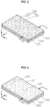
- step S10 of forming the alcohol-resolvable resin layer 120 first, as shown in FIGS. 1 and 2 , the metal sheet 110 is prepared (S11). That is, the metal sheet 110 shown in step S11 of FIG. 2 is prepared.
- the metal sheet 110 shown in step S11 of FIG. 2 is a cross-sectional view taken along line A-A of the metal sheet 110 shown in FIG. 3 .
- One of aluminum (Al), copper (Cu), nickel (Ni) and chrome (Cr) or a mixture of two or more materials of aluminum (Al), copper (Cu), nickel (Ni) and chrome (Cr) is used as the material of the metal sheet 110.
- FIG. 2 shows a first embodiment of a method of manufacturing a porous current collector according to an embodiment of the present invention.
- the alcohol-resolvable resin layer 120 is formed by coating the alcohol-resolvable resin on a surface of the metal sheet 110 (S12).
- the alcohol-resolvable resin layer 120 is formed by coating the alcohol-resolvable resin on a surface of one side of the metal sheet 110 (S1).
- the alcohol-resolvable resin layer 120 is formed by coating alcohol-resolvable resin on a surface of the other side opposite one side of the metal sheet 110 (S2).
- the alcohol-resolvable resin layer 120 shown in step S1 and step S2 is a cross-sectional view taken along line A-A of FIG. 3 .
- the alcohol-resolvable resin layer 120 is formed by mixing the alcohol-resolvable resin 5 to 50wt% and a solvent 50 to 95wt%.
- the alcohol-resolvable resin layer 120 is formed by mixing the alcohol-resolvable resin 5 to 50wt% and a solvent 50 to 95wt%.
- one of hydroxy polyester resin, acrylic resin, novolac resin and polyhydroxysterene is used as the alcohol-resolvable resin
- propylene glycol monomethyl ether acetate (PGMEA) is used as the solvent.
- the alcohol-resolvable resin layer 120 is dried by thermal treatment (S13) as shown in FIG. 1 .
- step S13 of drying the alcohol-resolvable resin layer 120 by thermal treatment the alcohol-resolvable resin layer 120 is dried in order to make volatile the solvent through the thermal treatment, and thermal treatment conditions are performed at a temperature of 50 to 200°C for 10 to 60 seconds. That is, the alcohol-resolvable resin layer 120 is formed by mixing the alcohol-resolvable resin 5 to 50wt% and the solvent 50 to 95wt%. Accordingly, in order to make volatile the solvent by drying the alcohol-resolvable resin layer 120, the thermal treatment is performed on the alcohol-resolvable resin layer 120 at a temperature of 50 to 200°C for 10 to 60 seconds.
- step S20 of forming the alcohol-resolvable mask pattern layer 120a is performed.
- step S20 of forming the alcohol-resolvable mask pattern layer 120a a plurality of through holes 121 is formed in the alcohol-resolvable mask pattern layer 120a. The plurality of through holes 121 is formed to penetrate the alcohol-resolvable resin layer 120 so that a surface of the metal sheet 110 is exposed.
- a polyhydric alcohol pattern layer 130 is formed by printing polyhydric alcohol on a surface of the alcohol-resolvable resin layer 120 (S21).
- the polyhydric alcohol pattern layer 130 is formed on one of the surfaces of the alcohol-resolvable resin layers 120 formed on the surfaces of one side and the other side of the metal sheet 110.
- the alcohol-resolvable resin layer 120 formed on a surface of the other side of the metal sheet 110 is used to protect the surface of the other side of the metal sheet 110 when the metal sheet 110 is etched.
- a plurality of cylindrical patterns 131 of the polyhydric alcohol pattern layer 130 is spaced apart and formed on the surface of the alcohol-resolvable resin layer 120. Only one of glycerin (or glycerine) and ethylene glycol is used as polyhydric alcohol.
- Glycerin or ethylene glycol has viscosity of 800 to 1500 centi Poise (cps), and polyvinyl alcohol (PVA) is added to ethylene glycol so that ethylene glycol has viscosity of 800 to 1500 cps, thereby being capable of forming the plurality of cylindrical patterns 131 using printing.
- the polyhydric alcohol pattern layer 130 shown in step S21 of FIG. 2 is a cross-sectional view taken along line A-A of FIG. 3 .
- step S22 of FIGS. 1 and 2 the alcohol-resolvable resin layer 120 is etched by performing thermal treatment on the polyhydric alcohol pattern layer 130, thereby forming the alcohol-resolvable mask pattern layer 120a (S22).
- the plurality of cylindrical patterns 131 indicated by alternate long and short dash lines in step S22 of FIG. 2 shows the state in which polyhydric alcohol has reacted to one of glycerin and ethylene glycol and the alcohol-resolvable resin by thermal treatment.
- the plurality of cylindrical patterns 131 of the polyhydric alcohol pattern layer 130 reacts to the alcohol-resolvable resin of the alcohol-resolvable resin layer 120 by the thermal treatment and etches the alcohol-resolvable resin located in accordance with a region in which the cylindrical pattern 131 has been located. Accordingly, the alcohol-resolvable mask pattern layer 120a having the plurality of through holes 121 is formed.
- the thermal treatment is performed at a temperature of 50 to 200°C for 10 to 60 seconds.
- the alcohol-resolvable mask pattern layer 120a is washed using pure water as in FIGS. 1 and 2 (S23).
- PVA polyvinyl alcohol
- the polyhydric alcohol pattern layer 130 indicated by alternate long and short dash lines in step S22 of FIG. 2 is removed so that only the metal sheet 110 and the alcohol-resolvable mask pattern layer 120a remain as in step S23 of FIG. 2 .
- the resolvable mask pattern layer 120a shown in step S23 of FIG. 2 is a cross-sectional view taken along line A-A of FIG. 4 .
- step S30 of performing etching so that the plurality of through holes 111 is formed in the metal sheet 110 as in FIGS. 1 , 2 and 3 , first, after the alcohol-resolvable mask pattern layer 120a is formed, the metal sheet 110 is etched by an etching solution so that the metal sheet 110 is penetrated using the alcohol-resolvable mask pattern layer 120a as a mask (S31).
- etching solution one of hydrogen chloride (HCI), nitric acid (HNO 3 ) and ferric chloride (FeCl 2 ) is used as the etching solution.
- HCI hydrogen chloride
- HNO 3 nitric acid
- FeCl 2 ferric chloride
- the alcohol-resolvable mask pattern layer 120a is fabricated as shown in step S32 of FIG. 2 by removing the alcohol-resolvable mask pattern layer 120a using caustic soda (NaOH) or an alkaline solution.
- the metal sheet 110 shown in step S32 of FIG. 2 is a cross-sectional view taken along line A-A of the metal sheet 110 in which the plurality of through holes 111 shown in FIG. 5 has been formed.
- FIG. 6 Another embodiment, that is, a second embodiment of the method of manufacturing a porous current collector according to an embodiment of the present invention, is shown in FIG. 6 .
- step S10 of forming the alcohol-resolvable resin layer 120 by coating alcohol-resolvable resin on a surface of the metal sheet 110 and step S30 of etching the metal sheet 110 using the alcohol-resolvable mask pattern layer 120a as a mask so that the plurality of through holes 111 is formed in the metal sheet 110 after the alcohol-resolvable mask pattern layer 120a is formed are the same as those of the method of manufacturing a porous current collector according to the first embodiment, and thus a description thereof is omitted.
- step S20 of forming the alcohol-resolvable mask pattern layer 120a by printing polyhydric alcohol on a surface of the alcohol-resolvable resin layer 120 the polyhydric alcohol pattern layers 130 are formed by printing polyhydric alcohol on surfaces of one side and the other side of the alcohol-resolvable resin layers 120 (S21).
- the plurality of cylindrical patterns 131 is spaced apart and formed on the surfaces of the alcohol-resolvable resin layers 120.
- the plurality of cylindrical patterns 131 formed on the surface of one side of the alcohol-resolvable resin layer 120 is formed at locations corresponding to the plurality of cylindrical patterns 131 formed on the surface of the other side of the alcohol-resolvable resin layer 120 as in step S21 of FIG. 6 .
- the alcohol-resolvable resin layer 120 may be formed in a rectangle or polygonal pattern (not shown) in addition to the plurality of cylindrical patterns 131.
- glycerin and ethylene glycol are used as polyhydric alcohol used to form the plurality of cylindrical patterns 131.
- Such glycerin or ethylene glycol has viscosity of 800 to 1500 cps as in the first embodiment of FIG. 2 .
- Polyvinyl alcohol (PVA) is added to ethylene glycol so that ethylene glycol has viscosity of 800 to 1500 cps, thereby being capable of forming the plurality of cylindrical patterns 131 using printing.
- step S22 of FIG. 6 the alcohol-resolvable resin layer 120 is etched by performing thermal treatment on the polyhydric alcohol pattern layer 130, thereby forming the alcohol-resolvable mask pattern layers 120a on surfaces of one side and the other side of the metal sheet 110 (S22).
- step S22 of FIG. 2 the plurality of cylindrical patterns 131 indicated by alternate long and short dash lines shows the state in which polyhydric alcohol has reacted to one of glycerin and ethylene glycol and alcohol-resolvable resin by the thermal treatment.
- the plurality of cylindrical patterns 131 of the polyhydric alcohol pattern layer 130 reacts to the alcohol-resolvable resin on the surfaces of the one side and the other sides of the alcohol-resolvable resin layers 120 by the thermal treatment. Accordingly, the alcohol-resolvable resin located in accordance with the region in which the cylindrical pattern 131 has been formed is etched to form the alcohol-resolvable mask pattern layer 120a having the plurality of through holes 121. In this case, conditions in which the thermal treatment is performed the polyhydric alcohol pattern layer 130 are performed at a temperature of 100 to 150°C for 10 to 60 seconds.
- the alcohol-resolvable mask pattern layers 120a are washed using pure water (S23).
- pure water pure water
- PVA used for viscosity of glycerin or ethylene glycol used as polyhydric alcohol is removed by washing. Accordingly, the polyhydric alcohol pattern layer 130 indicated by the alternate long and short dash lines in step S22 of FIG. 2 is removed so that only the metal sheet 110 and the alcohol-resolvable mask pattern layers 120a remain as in step S23 of FIG. 6 .
- step S30 of etching the metal sheet 110 so that the plurality of through holes 111 is formed in the metal sheet 110 is the same as that described above, and a description thereof is omitted.
- step S30 of etching the metal sheet 110 so that the plurality of through holes 111 is formed according to the first embodiment and the second embodiment if the metal sheet 110 is made of an aluminum (Al) material, 6 to 8M (molarity) hydrogen chloride (HCI) is used as an etching solution, so a porous current collector having an opening ratio of 1 to 30% can be fabricated in the metal sheet 110 made of aluminum (Al).
- the metal sheet 110 is made of a copper (Cu) material, it is processed for 5 to 20 seconds using nitric acid (HNO 3 ) of a 20 to 40% concentration using an etching solution, thereby being capable of fabricating a porous current collector having an opening ratio of 1 to 30% in the metal sheet 110 made of the copper (Cu) material.
- HNO 3 nitric acid
- a known method is applied to the calculation of the opening ratio and a description thereof is omitted.
- the porous current collector has the state in which the plurality of through holes 111 has been formed in the metal sheet 110
- the alcohol-resolvable mask pattern layer 120a is printed on a surface of the alcohol-resolvable resin layer 120 formed using alcohol-resolvable resin in a pattern using polyhydric alcohol.
- the alcohol-resolvable resin layer 120 is fabricated to have an etch mask pattern, the plurality of through holes is formed in the metal sheet using the etch mask pattern, thereby fabricating the porous current collector. Accordingly, a manufacturing cost of the porous current collector can be reduced and productivity can be improved.
- the method of manufacturing a porous current collector according to an embodiment of the present invention may be applied to the industrial fields for manufacturing a super capacitor and secondary cell, such as an EDLC.
- the method of manufacturing a porous current collector in the method of manufacturing a porous current collector according to an embodiment of the present invention, after the alcohol-resolvable resin is fabricated in an etch mask pattern by printing polyhydric alcohol on a surface of the alcohol-resolvable resin, the plurality of through holes is formed in the metal sheet using the etch mask pattern, thereby fabricating the porous current collector. Accordingly, a manufacturing cost of the porous current collector can be reduced and productivity can be improved.
Landscapes
- Engineering & Computer Science (AREA)
- Chemical & Material Sciences (AREA)
- Power Engineering (AREA)
- Chemical Kinetics & Catalysis (AREA)
- General Chemical & Material Sciences (AREA)
- Materials Engineering (AREA)
- Microelectronics & Electronic Packaging (AREA)
- Mechanical Engineering (AREA)
- Metallurgy (AREA)
- Organic Chemistry (AREA)
- Electrochemistry (AREA)
- Manufacturing & Machinery (AREA)
- ing And Chemical Polishing (AREA)
- Laminated Bodies (AREA)
- Electric Double-Layer Capacitors Or The Like (AREA)
- Cell Electrode Carriers And Collectors (AREA)
- Manufacture Or Reproduction Of Printing Formes (AREA)
Claims (14)
- Verfahren zur Herstellung eines porösen Stromkollektors, umfassend die Schritte:Ausbilden einer alkohollöslichen Harzschicht durch Auftragen von alkohollöslichem Harz auf eine Oberfläche eines Metallblechs;Ausbilden einer alkohollöslichen Maskierungsmusterschicht durch Drucken von mehrwertigem Alkohol auf eine Oberfläche der alkohollöslichen Harzschicht, nachdem die alkohollösliche Harzschicht ausgebildet wurde; undÄtzen des Metallblechs derart, dass eine Vielzahl von Durchgangslöchern in dem Metallblech ausgebildet wird, wobei die alkohollösliche Maskierungsmusterschicht als eine Maskierung verwendet wird, nachdem die alkohollösliche Maskierungsmusterschicht ausgebildet wurde.
- Verfahren nach Anspruch 1, wobei der Schritt des Ausbildens der alkohollöslichen Harzschicht die Schritte umfasst:Vorbereiten des Metallblechs;Ausbilden der alkohollöslichen Harzschicht durch Auftragen des alkohollöslichen Harzes auf die Oberfläche des Metallblechs, nachdem das Metallblech vorbereitet wurde; undTrocknen der alkohollöslichen Harzschicht durch Wärmebehandlung, nachdem die alkohollösliche Harzschicht auf der Oberfläche des Metallblechs ausgebildet wurde.
- Verfahren nach Anspruch 2, wobei bei dem Schritt des Herstellens des Metallblechs eines von Aluminium (Al), Kupfer (Cu), Nickel (Ni) und Chrom (Cr) oder eine Mischung aus zwei oder mehr Materialien von Aluminium (Al), Kupfer (Cu), Nickel (Ni) und Chrom (Cr) als Material des Metallblechs verwendet wird.
- Verfahren nach Anspruch 2, wobei der Schritt des Ausbildens der alkohollöslichen Harzschicht die Schritte umfasst:Ausbilden einer alkohollöslichen Harzschicht durch Auftragen des alkohollöslichen Harzes auf eine Oberfläche einer Seite des Metallblechs, nachdem das Metallblech vorbereitet wurde; undAusbilden einer alkohollöslichen Harzschicht durch Auftragen des alkohollöslichen Harzes auf eine Oberfläche der anderen Seite des Metallblechs gegenüber einer Seite des Metallblechs, nachdem die alkohollösliche Harzschicht auf der Oberfläche einer Seite des Metallblechs ausgebildet wurde.
- Verfahren nach Anspruch 4, wobei bei dem Schritt des Ausbildens der alkohollöslichen Harzschicht durch Auftragen des alkohollöslichen Harzes auf die Oberfläche einer Seite oder der anderen Seite des Metallblechs die alkohollösliche Harzschicht durch Mischen von 5 bis 50 Gew.-% des alkohollöslichen Harzes und 50 bis 95 Gew.-% eines Lösungsmittels gebildet wird, eines von Hydroxypolyesterharz, Acrylharz, Novolakharz und Polyhydroxystyrol als das alkohollösliche Harz verwendet wird, und Propylenglycolmonomethyletheracetat (PGMEA) als das Lösungsmittel verwendet wird.
- Verfahren nach Anspruch 4, wobei bei dem Schritt des Trocknens der alkohollöslichen Harzschicht durch die Wärmebehandlung, die Wärmebehandlung durchgeführt wird, um die alkohollösliche Harzschicht zu trocknen, um das Lösungsmittel flüchtig zu machen, und die Bedingungen für die Wärmebehandlung bei einer Temperatur von 50 bis 200°C für 10 bis 60 Sekunden durchgeführt werden.
- Verfahren nach Anspruch 1, wobei bei dem Schritt des Ausbildens der alkohollöslichen Maskierungsmusterschicht eine Vielzahl von Durchgangslöchern in der alkohollöslichen Maskierungsmusterschicht ausgebildet wird, und die Vielzahl von Durchgangslöchern so ausgebildet wird, dass sie die alkohollösliche Harzschicht derart durchdringt, dass die Oberfläche des Metallblechs freiliegt.
- Verfahren nach Anspruch 1, wobei der Schritt des Ausbildens der alkohollöslichen Maskierungsmusterschicht die Schritte umfasst:Ausbilden einer Musterschicht aus mehrwertigem Alkohol durch Drucken von mehrwertigem Alkohol auf eine Oberfläche der alkohollöslichen Harzschicht, nachdem die alkohollösliche Harzschicht ausgebildet wurde; undAusbilden der alkohollöslichen Maskierungsmusterschicht durch Ätzen der alkohollöslichen Harzschicht durch Durchführen einer Wärmebehandlung an der Musterschicht aus mehrwertigem Alkohol, nachdem die Musterschicht aus mehrwertigem Alkohol ausgebildet wurde; undWaschen der alkohollöslichen Maskierungsmusterschicht unter Verwendung von reinem Wasser, nachdem die alkohollösliche Maskierungsmusterschicht ausgebildet wurde.
- Verfahren nach Anspruch 8, wobei bei dem Schritt des Ausbildens der Musterschicht aus mehrwertigem Alkohol durch Drucken des mehrwertigen Alkohols eine Vielzahl von zylindrischen Mustern der Musterschicht aus mehrwertigem Alkohol voneinander beabstandet und in einer Oberfläche der alkohollöslichen Harzschicht ausgebildet wird.
- Verfahren nach Anspruch 7, wobei bei dem Schritt des Ausbildens der Musterschicht aus mehrwertigem Alkohol durch Drucken des mehrwertigen Alkohols nur eines von Glycerin und Ethylenglycol als mehrwertiger Alkohol verwendet wird, wobei Glycerin oder Ethylenglycol verwendet wird, die eine Viskosität von 800 bis 1500 Centipoise (cPs) haben, und das Ethylenglycol eine Viskosität von 800 bis 1500 cPs durch Zugabe von Polyvinylalkohol (PVA) aufweist.
- Verfahren nach Anspruch 7, wobei bei dem Schritt des Ausbildens der alkohollöslichen Maskierungsmusterschicht eine Wärmebehandlung bei einer Temperatur von 100 bis 150°C für 10 bis 60 Sekunden durchgeführt wird.
- Verfahren nach Anspruch 1, wobei der Schritt des Ätzens des Metallblechs derart, dass die Vielzahl von Durchgangslöchern in dem Metallblech ausgebildet wird, die Schritte umfasst:Ätzen des Metallblechs derart, dass das Metallblech von einer Ätzlösung durchdrungen wird, wobei die alkohollösliche Maskierungsmusterschicht als eine Maskierung verwendet wird, nachdem die alkohollösliche Maskierungsmusterschicht ausgebildet wurde; undEntfernen der alkohollöslichen Maskierungsmusterschicht durch Ätzen, nachdem das Metallblech durch Ätzen durchdrungen wurde.
- Verfahren nach Anspruch 12, wobei bei dem Schritt des Ätzens des Metallblechs derart, dass die Vielzahl von Durchgangslöchern in dem Metallblech ausgebildet wird, eines von Chlorwasserstoff (HCl), Salpetersäure (HNO3) und Eisenchlorid (FeCl2) als die Ätzlösung verwendet wird.
- Verfahren nach Anspruch 12, wobei bei dem Schritt des Entfernens der alkohollöslichen Maskierungsmusterschicht durch Ätzen die alkohollösliche Maskierungsmusterschicht unter Verwendung von kaustischem Soda (NaOH) oder einer alkalischen Lösung entfernt wird.
Applications Claiming Priority (1)
| Application Number | Priority Date | Filing Date | Title |
|---|---|---|---|
| KR1020170170235A KR102028458B1 (ko) | 2017-12-12 | 2017-12-12 | 관통박 제조방법 |
Publications (2)
| Publication Number | Publication Date |
|---|---|
| EP3499534A1 EP3499534A1 (de) | 2019-06-19 |
| EP3499534B1 true EP3499534B1 (de) | 2020-09-09 |
Family
ID=63173929
Family Applications (1)
| Application Number | Title | Priority Date | Filing Date |
|---|---|---|---|
| EP18185427.4A Active EP3499534B1 (de) | 2017-12-12 | 2018-07-25 | Verfahren zum herstellen eines porösen stromkollektors |
Country Status (5)
| Country | Link |
|---|---|
| US (1) | US10096433B1 (de) |
| EP (1) | EP3499534B1 (de) |
| JP (1) | JP6514385B1 (de) |
| KR (1) | KR102028458B1 (de) |
| CN (1) | CN109913705B (de) |
Families Citing this family (5)
| Publication number | Priority date | Publication date | Assignee | Title |
|---|---|---|---|---|
| KR102187762B1 (ko) * | 2018-12-27 | 2020-12-07 | 한국제이씨씨(주) | 교류에칭을 이용한 관통형 에칭박 제조방법 |
| KR102187761B1 (ko) * | 2018-12-27 | 2020-12-07 | 한국제이씨씨(주) | 계면저항을 개선하기 위한 관통형 에칭박 제조방법 |
| KR102114963B1 (ko) * | 2018-12-31 | 2020-05-25 | 한국제이씨씨(주) | 전기 이중층 커패시터의 전극제조방법 |
| KR102762515B1 (ko) | 2019-11-19 | 2025-02-05 | 주식회사 엘지에너지솔루션 | 전극 조립체 및 그의 제조 방법 |
| CN114744208B (zh) * | 2022-03-29 | 2023-02-10 | 佛山市中技烯米新材料有限公司 | 一种集流体刻蚀箔材及其制备方法、电极、锂电池 |
Family Cites Families (14)
| Publication number | Priority date | Publication date | Assignee | Title |
|---|---|---|---|---|
| US3482976A (en) * | 1966-12-27 | 1969-12-09 | Gen Electric | Photolytic etching of gold |
| US4448637A (en) * | 1981-12-28 | 1984-05-15 | Daicel Chemical Industries, Ltd. | Etching method of conductive film |
| JP3624966B2 (ja) * | 1995-06-01 | 2005-03-02 | 日立化成工業株式会社 | 多層プリント配線板の製造方法及びその製造方法に用いるエッチング液 |
| US6890677B2 (en) * | 1999-05-06 | 2005-05-10 | Sandia Corporation | Fuel cell and membrane |
| JP4019960B2 (ja) | 2003-01-31 | 2007-12-12 | 三菱電機株式会社 | 基板の製造方法 |
| JP4928762B2 (ja) | 2005-09-27 | 2012-05-09 | 株式会社リコー | 貫通孔を有する厚膜の製造方法、及び貫通孔を有する厚膜 |
| JP2010015974A (ja) * | 2008-03-28 | 2010-01-21 | Fuji Heavy Ind Ltd | 電極の製造方法、蓄電デバイス、および中間積層材 |
| JP2012003970A (ja) | 2010-06-17 | 2012-01-05 | Finecs Kk | 二次電池用金属箔および二次電池 |
| CN103352224B (zh) * | 2013-07-01 | 2015-09-23 | 广东工业大学 | 一种用于金属制品的双面蚀刻方法 |
| KR20160011666A (ko) * | 2013-09-19 | 2016-02-01 | 가부시키가이샤 제이올레드 | 유기 발광 소자의 제조 방법 및 표시 장치의 제조 방법 |
| KR101685559B1 (ko) | 2014-05-14 | 2016-12-12 | 한국제이씨씨(주) | 전기 이중층 커패시터의 고밀도 전극의 제조방법 |
| JP6109896B2 (ja) * | 2015-09-03 | 2017-04-05 | 日新製鋼株式会社 | 金属板からレジスト膜を除去する方法およびエッチングされた金属板の製造方法 |
| US9447504B1 (en) * | 2015-09-28 | 2016-09-20 | Xerox Corporation | Method of etching using inkjet printing |
| KR20170122448A (ko) * | 2016-04-27 | 2017-11-06 | 박상민 | 패턴층 및 절연층을 포함하는 인쇄회로기판 및 이의 제조방법 |
-
2017
- 2017-12-12 KR KR1020170170235A patent/KR102028458B1/ko active Active
-
2018
- 2018-03-22 CN CN201810237703.4A patent/CN109913705B/zh not_active Expired - Fee Related
- 2018-03-28 US US15/938,303 patent/US10096433B1/en active Active
- 2018-03-29 JP JP2018063767A patent/JP6514385B1/ja active Active
- 2018-07-25 EP EP18185427.4A patent/EP3499534B1/de active Active
Non-Patent Citations (1)
| Title |
|---|
| None * |
Also Published As
| Publication number | Publication date |
|---|---|
| US10096433B1 (en) | 2018-10-09 |
| KR102028458B1 (ko) | 2019-10-04 |
| CN109913705A (zh) | 2019-06-21 |
| EP3499534A1 (de) | 2019-06-19 |
| KR20190069891A (ko) | 2019-06-20 |
| CN109913705B (zh) | 2021-11-26 |
| JP6514385B1 (ja) | 2019-05-15 |
| JP2019104983A (ja) | 2019-06-27 |
Similar Documents
| Publication | Publication Date | Title |
|---|---|---|
| EP3499534B1 (de) | Verfahren zum herstellen eines porösen stromkollektors | |
| JP6958597B2 (ja) | メタルマスク用基材の製造方法、および、蒸着用メタルマスクの製造方法 | |
| EP2825006B1 (de) | Verfahren zur Herstellung einer isolierten leitfähigen Struktur | |
| JP2019014895A5 (de) | ||
| DE10203143A1 (de) | Elektroden, deren Herstellung und Kondensatoren mit den Elektroden | |
| KR20120096438A (ko) | 전해콘덴서 및 전해콘덴서의 제조방법 | |
| CN108713233B (zh) | 电解电容器 | |
| DE112016005410T5 (de) | Elektrolytkondensator und Verfahren zur seiner Herstellung | |
| CN101271779B (zh) | 固体电解质电容器及其制造方法 | |
| KR20110076835A (ko) | 전해콘덴서 | |
| DE102014223873B3 (de) | Verfahren zur Herstellung eines aufgerollten elektrischen oder elektronischen Bauelements | |
| JP2009218501A (ja) | 電解コンデンサ用金属箔の製造方法、及び電解コンデンサ | |
| JPWO2023145891A5 (de) | ||
| JP5419546B2 (ja) | 表面実装薄型コンデンサ及びその製造方法 | |
| JP2007261144A (ja) | 反転オフセット印刷用除去版およびパターン形成方法 | |
| EP2442324A1 (de) | Verfahren zur Herstellung eines Feststoffelektrolytkondensators | |
| CN100590760C (zh) | 固体电解电容器及其制造方法 | |
| KR102187762B1 (ko) | 교류에칭을 이용한 관통형 에칭박 제조방법 | |
| JP5334756B2 (ja) | 電解コンデンサ | |
| CN114182202B (zh) | 电子器件金属图形的微加工方法 | |
| CN113651290B (zh) | 一种新的硅基微纳结构的修饰方法 | |
| KR102114963B1 (ko) | 전기 이중층 커패시터의 전극제조방법 | |
| WO2013016931A1 (zh) | 一种基于缓冲层进行深刻蚀的掩蔽方法 | |
| JP2011006733A (ja) | エッチング加工済み金属箔、エッチング加工済み金属箔の製造方法、およびエッチング加工済み金属箔製造装置 | |
| CN109680306B (zh) | 基于机械打孔的fmm电铸母板制作方法 |
Legal Events
| Date | Code | Title | Description |
|---|---|---|---|
| PUAI | Public reference made under article 153(3) epc to a published international application that has entered the european phase |
Free format text: ORIGINAL CODE: 0009012 |
|
| STAA | Information on the status of an ep patent application or granted ep patent |
Free format text: STATUS: REQUEST FOR EXAMINATION WAS MADE |
|
| 17P | Request for examination filed |
Effective date: 20180725 |
|
| AK | Designated contracting states |
Kind code of ref document: A1 Designated state(s): AL AT BE BG CH CY CZ DE DK EE ES FI FR GB GR HR HU IE IS IT LI LT LU LV MC MK MT NL NO PL PT RO RS SE SI SK SM TR |
|
| AX | Request for extension of the european patent |
Extension state: BA ME |
|
| GRAP | Despatch of communication of intention to grant a patent |
Free format text: ORIGINAL CODE: EPIDOSNIGR1 |
|
| STAA | Information on the status of an ep patent application or granted ep patent |
Free format text: STATUS: GRANT OF PATENT IS INTENDED |
|
| RIC1 | Information provided on ipc code assigned before grant |
Ipc: H01G 11/70 20130101ALI20200313BHEP Ipc: C23F 1/20 20060101ALI20200313BHEP Ipc: H01M 4/66 20060101ALI20200313BHEP Ipc: H01M 4/70 20060101ALI20200313BHEP Ipc: H01G 11/84 20130101AFI20200313BHEP Ipc: H01M 4/80 20060101ALI20200313BHEP Ipc: C23F 1/18 20060101ALI20200313BHEP Ipc: C23F 1/02 20060101ALI20200313BHEP Ipc: H01G 11/28 20130101ALI20200313BHEP Ipc: H01M 4/72 20060101ALI20200313BHEP |
|
| INTG | Intention to grant announced |
Effective date: 20200407 |
|
| GRAS | Grant fee paid |
Free format text: ORIGINAL CODE: EPIDOSNIGR3 |
|
| GRAA | (expected) grant |
Free format text: ORIGINAL CODE: 0009210 |
|
| STAA | Information on the status of an ep patent application or granted ep patent |
Free format text: STATUS: THE PATENT HAS BEEN GRANTED |
|
| AK | Designated contracting states |
Kind code of ref document: B1 Designated state(s): AL AT BE BG CH CY CZ DE DK EE ES FI FR GB GR HR HU IE IS IT LI LT LU LV MC MK MT NL NO PL PT RO RS SE SI SK SM TR |
|
| REG | Reference to a national code |
Ref country code: GB Ref legal event code: FG4D |
|
| REG | Reference to a national code |
Ref country code: AT Ref legal event code: REF Ref document number: 1312611 Country of ref document: AT Kind code of ref document: T Effective date: 20200915 Ref country code: CH Ref legal event code: EP |
|
| REG | Reference to a national code |
Ref country code: IE Ref legal event code: FG4D |
|
| REG | Reference to a national code |
Ref country code: DE Ref legal event code: R096 Ref document number: 602018007561 Country of ref document: DE |
|
| REG | Reference to a national code |
Ref country code: LT Ref legal event code: MG4D |
|
| PG25 | Lapsed in a contracting state [announced via postgrant information from national office to epo] |
Ref country code: GR Free format text: LAPSE BECAUSE OF FAILURE TO SUBMIT A TRANSLATION OF THE DESCRIPTION OR TO PAY THE FEE WITHIN THE PRESCRIBED TIME-LIMIT Effective date: 20201210 Ref country code: LT Free format text: LAPSE BECAUSE OF FAILURE TO SUBMIT A TRANSLATION OF THE DESCRIPTION OR TO PAY THE FEE WITHIN THE PRESCRIBED TIME-LIMIT Effective date: 20200909 Ref country code: FI Free format text: LAPSE BECAUSE OF FAILURE TO SUBMIT A TRANSLATION OF THE DESCRIPTION OR TO PAY THE FEE WITHIN THE PRESCRIBED TIME-LIMIT Effective date: 20200909 Ref country code: SE Free format text: LAPSE BECAUSE OF FAILURE TO SUBMIT A TRANSLATION OF THE DESCRIPTION OR TO PAY THE FEE WITHIN THE PRESCRIBED TIME-LIMIT Effective date: 20200909 Ref country code: HR Free format text: LAPSE BECAUSE OF FAILURE TO SUBMIT A TRANSLATION OF THE DESCRIPTION OR TO PAY THE FEE WITHIN THE PRESCRIBED TIME-LIMIT Effective date: 20200909 Ref country code: NO Free format text: LAPSE BECAUSE OF FAILURE TO SUBMIT A TRANSLATION OF THE DESCRIPTION OR TO PAY THE FEE WITHIN THE PRESCRIBED TIME-LIMIT Effective date: 20201209 Ref country code: BG Free format text: LAPSE BECAUSE OF FAILURE TO SUBMIT A TRANSLATION OF THE DESCRIPTION OR TO PAY THE FEE WITHIN THE PRESCRIBED TIME-LIMIT Effective date: 20201209 |
|
| REG | Reference to a national code |
Ref country code: AT Ref legal event code: MK05 Ref document number: 1312611 Country of ref document: AT Kind code of ref document: T Effective date: 20200909 |
|
| REG | Reference to a national code |
Ref country code: NL Ref legal event code: MP Effective date: 20200909 |
|
| PG25 | Lapsed in a contracting state [announced via postgrant information from national office to epo] |
Ref country code: RS Free format text: LAPSE BECAUSE OF FAILURE TO SUBMIT A TRANSLATION OF THE DESCRIPTION OR TO PAY THE FEE WITHIN THE PRESCRIBED TIME-LIMIT Effective date: 20200909 Ref country code: PL Free format text: LAPSE BECAUSE OF FAILURE TO SUBMIT A TRANSLATION OF THE DESCRIPTION OR TO PAY THE FEE WITHIN THE PRESCRIBED TIME-LIMIT Effective date: 20200909 Ref country code: LV Free format text: LAPSE BECAUSE OF FAILURE TO SUBMIT A TRANSLATION OF THE DESCRIPTION OR TO PAY THE FEE WITHIN THE PRESCRIBED TIME-LIMIT Effective date: 20200909 |
|
| PG25 | Lapsed in a contracting state [announced via postgrant information from national office to epo] |
Ref country code: SM Free format text: LAPSE BECAUSE OF FAILURE TO SUBMIT A TRANSLATION OF THE DESCRIPTION OR TO PAY THE FEE WITHIN THE PRESCRIBED TIME-LIMIT Effective date: 20200909 Ref country code: RO Free format text: LAPSE BECAUSE OF FAILURE TO SUBMIT A TRANSLATION OF THE DESCRIPTION OR TO PAY THE FEE WITHIN THE PRESCRIBED TIME-LIMIT Effective date: 20200909 Ref country code: PT Free format text: LAPSE BECAUSE OF FAILURE TO SUBMIT A TRANSLATION OF THE DESCRIPTION OR TO PAY THE FEE WITHIN THE PRESCRIBED TIME-LIMIT Effective date: 20210111 Ref country code: CZ Free format text: LAPSE BECAUSE OF FAILURE TO SUBMIT A TRANSLATION OF THE DESCRIPTION OR TO PAY THE FEE WITHIN THE PRESCRIBED TIME-LIMIT Effective date: 20200909 Ref country code: EE Free format text: LAPSE BECAUSE OF FAILURE TO SUBMIT A TRANSLATION OF THE DESCRIPTION OR TO PAY THE FEE WITHIN THE PRESCRIBED TIME-LIMIT Effective date: 20200909 |
|
| PG25 | Lapsed in a contracting state [announced via postgrant information from national office to epo] |
Ref country code: AL Free format text: LAPSE BECAUSE OF FAILURE TO SUBMIT A TRANSLATION OF THE DESCRIPTION OR TO PAY THE FEE WITHIN THE PRESCRIBED TIME-LIMIT Effective date: 20200909 Ref country code: AT Free format text: LAPSE BECAUSE OF FAILURE TO SUBMIT A TRANSLATION OF THE DESCRIPTION OR TO PAY THE FEE WITHIN THE PRESCRIBED TIME-LIMIT Effective date: 20200909 Ref country code: ES Free format text: LAPSE BECAUSE OF FAILURE TO SUBMIT A TRANSLATION OF THE DESCRIPTION OR TO PAY THE FEE WITHIN THE PRESCRIBED TIME-LIMIT Effective date: 20200909 Ref country code: IS Free format text: LAPSE BECAUSE OF FAILURE TO SUBMIT A TRANSLATION OF THE DESCRIPTION OR TO PAY THE FEE WITHIN THE PRESCRIBED TIME-LIMIT Effective date: 20210109 |
|
| REG | Reference to a national code |
Ref country code: DE Ref legal event code: R097 Ref document number: 602018007561 Country of ref document: DE |
|
| PG25 | Lapsed in a contracting state [announced via postgrant information from national office to epo] |
Ref country code: SK Free format text: LAPSE BECAUSE OF FAILURE TO SUBMIT A TRANSLATION OF THE DESCRIPTION OR TO PAY THE FEE WITHIN THE PRESCRIBED TIME-LIMIT Effective date: 20200909 |
|
| PLBE | No opposition filed within time limit |
Free format text: ORIGINAL CODE: 0009261 |
|
| STAA | Information on the status of an ep patent application or granted ep patent |
Free format text: STATUS: NO OPPOSITION FILED WITHIN TIME LIMIT |
|
| 26N | No opposition filed |
Effective date: 20210610 |
|
| PG25 | Lapsed in a contracting state [announced via postgrant information from national office to epo] |
Ref country code: DK Free format text: LAPSE BECAUSE OF FAILURE TO SUBMIT A TRANSLATION OF THE DESCRIPTION OR TO PAY THE FEE WITHIN THE PRESCRIBED TIME-LIMIT Effective date: 20200909 Ref country code: SI Free format text: LAPSE BECAUSE OF FAILURE TO SUBMIT A TRANSLATION OF THE DESCRIPTION OR TO PAY THE FEE WITHIN THE PRESCRIBED TIME-LIMIT Effective date: 20200909 |
|
| REG | Reference to a national code |
Ref country code: CH Ref legal event code: PL |
|
| PG25 | Lapsed in a contracting state [announced via postgrant information from national office to epo] |
Ref country code: MC Free format text: LAPSE BECAUSE OF FAILURE TO SUBMIT A TRANSLATION OF THE DESCRIPTION OR TO PAY THE FEE WITHIN THE PRESCRIBED TIME-LIMIT Effective date: 20200909 |
|
| REG | Reference to a national code |
Ref country code: BE Ref legal event code: MM Effective date: 20210731 |
|
| PG25 | Lapsed in a contracting state [announced via postgrant information from national office to epo] |
Ref country code: LI Free format text: LAPSE BECAUSE OF NON-PAYMENT OF DUE FEES Effective date: 20210731 Ref country code: CH Free format text: LAPSE BECAUSE OF NON-PAYMENT OF DUE FEES Effective date: 20210731 |
|
| PG25 | Lapsed in a contracting state [announced via postgrant information from national office to epo] |
Ref country code: LU Free format text: LAPSE BECAUSE OF NON-PAYMENT OF DUE FEES Effective date: 20210725 Ref country code: FR Free format text: LAPSE BECAUSE OF NON-PAYMENT OF DUE FEES Effective date: 20210731 |
|
| PG25 | Lapsed in a contracting state [announced via postgrant information from national office to epo] |
Ref country code: IE Free format text: LAPSE BECAUSE OF NON-PAYMENT OF DUE FEES Effective date: 20210725 Ref country code: BE Free format text: LAPSE BECAUSE OF NON-PAYMENT OF DUE FEES Effective date: 20210731 |
|
| GBPC | Gb: european patent ceased through non-payment of renewal fee |
Effective date: 20220725 |
|
| PG25 | Lapsed in a contracting state [announced via postgrant information from national office to epo] |
Ref country code: GB Free format text: LAPSE BECAUSE OF NON-PAYMENT OF DUE FEES Effective date: 20220725 |
|
| PG25 | Lapsed in a contracting state [announced via postgrant information from national office to epo] |
Ref country code: NL Free format text: LAPSE BECAUSE OF NON-PAYMENT OF DUE FEES Effective date: 20200923 Ref country code: CY Free format text: LAPSE BECAUSE OF FAILURE TO SUBMIT A TRANSLATION OF THE DESCRIPTION OR TO PAY THE FEE WITHIN THE PRESCRIBED TIME-LIMIT Effective date: 20200909 |
|
| PG25 | Lapsed in a contracting state [announced via postgrant information from national office to epo] |
Ref country code: HU Free format text: LAPSE BECAUSE OF FAILURE TO SUBMIT A TRANSLATION OF THE DESCRIPTION OR TO PAY THE FEE WITHIN THE PRESCRIBED TIME-LIMIT; INVALID AB INITIO Effective date: 20180725 |
|
| PG25 | Lapsed in a contracting state [announced via postgrant information from national office to epo] |
Ref country code: MK Free format text: LAPSE BECAUSE OF FAILURE TO SUBMIT A TRANSLATION OF THE DESCRIPTION OR TO PAY THE FEE WITHIN THE PRESCRIBED TIME-LIMIT Effective date: 20200909 |
|
| PG25 | Lapsed in a contracting state [announced via postgrant information from national office to epo] |
Ref country code: MT Free format text: LAPSE BECAUSE OF FAILURE TO SUBMIT A TRANSLATION OF THE DESCRIPTION OR TO PAY THE FEE WITHIN THE PRESCRIBED TIME-LIMIT Effective date: 20200909 |
|
| PGFP | Annual fee paid to national office [announced via postgrant information from national office to epo] |
Ref country code: DE Payment date: 20250729 Year of fee payment: 8 |
|
| PGFP | Annual fee paid to national office [announced via postgrant information from national office to epo] |
Ref country code: IT Payment date: 20250728 Year of fee payment: 8 |
|
| PG25 | Lapsed in a contracting state [announced via postgrant information from national office to epo] |
Ref country code: TR Free format text: LAPSE BECAUSE OF FAILURE TO SUBMIT A TRANSLATION OF THE DESCRIPTION OR TO PAY THE FEE WITHIN THE PRESCRIBED TIME-LIMIT Effective date: 20200909 |