EP3499151B1 - Expansion valve - Google Patents
Expansion valve Download PDFInfo
- Publication number
- EP3499151B1 EP3499151B1 EP17839189.2A EP17839189A EP3499151B1 EP 3499151 B1 EP3499151 B1 EP 3499151B1 EP 17839189 A EP17839189 A EP 17839189A EP 3499151 B1 EP3499151 B1 EP 3499151B1
- Authority
- EP
- European Patent Office
- Prior art keywords
- valve
- vibration isolation
- isolation spring
- leg portions
- portions
- Prior art date
- Legal status (The legal status is an assumption and is not a legal conclusion. Google has not performed a legal analysis and makes no representation as to the accuracy of the status listed.)
- Active
Links
Images




Classifications
-
- F—MECHANICAL ENGINEERING; LIGHTING; HEATING; WEAPONS; BLASTING
- F25—REFRIGERATION OR COOLING; COMBINED HEATING AND REFRIGERATION SYSTEMS; HEAT PUMP SYSTEMS; MANUFACTURE OR STORAGE OF ICE; LIQUEFACTION SOLIDIFICATION OF GASES
- F25B—REFRIGERATION MACHINES, PLANTS OR SYSTEMS; COMBINED HEATING AND REFRIGERATION SYSTEMS; HEAT PUMP SYSTEMS
- F25B41/00—Fluid-circulation arrangements
- F25B41/30—Expansion means; Dispositions thereof
- F25B41/31—Expansion valves
- F25B41/33—Expansion valves with the valve member being actuated by the fluid pressure, e.g. by the pressure of the refrigerant
- F25B41/335—Expansion valves with the valve member being actuated by the fluid pressure, e.g. by the pressure of the refrigerant via diaphragms
-
- F—MECHANICAL ENGINEERING; LIGHTING; HEATING; WEAPONS; BLASTING
- F16—ENGINEERING ELEMENTS AND UNITS; GENERAL MEASURES FOR PRODUCING AND MAINTAINING EFFECTIVE FUNCTIONING OF MACHINES OR INSTALLATIONS; THERMAL INSULATION IN GENERAL
- F16K—VALVES; TAPS; COCKS; ACTUATING-FLOATS; DEVICES FOR VENTING OR AERATING
- F16K1/00—Lift valves or globe valves, i.e. cut-off apparatus with closure members having at least a component of their opening and closing motion perpendicular to the closing faces
- F16K1/14—Lift valves or globe valves, i.e. cut-off apparatus with closure members having at least a component of their opening and closing motion perpendicular to the closing faces with ball-shaped valve member
-
- F—MECHANICAL ENGINEERING; LIGHTING; HEATING; WEAPONS; BLASTING
- F16—ENGINEERING ELEMENTS AND UNITS; GENERAL MEASURES FOR PRODUCING AND MAINTAINING EFFECTIVE FUNCTIONING OF MACHINES OR INSTALLATIONS; THERMAL INSULATION IN GENERAL
- F16K—VALVES; TAPS; COCKS; ACTUATING-FLOATS; DEVICES FOR VENTING OR AERATING
- F16K1/00—Lift valves or globe valves, i.e. cut-off apparatus with closure members having at least a component of their opening and closing motion perpendicular to the closing faces
- F16K1/32—Details
-
- F—MECHANICAL ENGINEERING; LIGHTING; HEATING; WEAPONS; BLASTING
- F16—ENGINEERING ELEMENTS AND UNITS; GENERAL MEASURES FOR PRODUCING AND MAINTAINING EFFECTIVE FUNCTIONING OF MACHINES OR INSTALLATIONS; THERMAL INSULATION IN GENERAL
- F16K—VALVES; TAPS; COCKS; ACTUATING-FLOATS; DEVICES FOR VENTING OR AERATING
- F16K31/00—Actuating devices; Operating means; Releasing devices
- F16K31/002—Actuating devices; Operating means; Releasing devices actuated by temperature variation
-
- F—MECHANICAL ENGINEERING; LIGHTING; HEATING; WEAPONS; BLASTING
- F16—ENGINEERING ELEMENTS AND UNITS; GENERAL MEASURES FOR PRODUCING AND MAINTAINING EFFECTIVE FUNCTIONING OF MACHINES OR INSTALLATIONS; THERMAL INSULATION IN GENERAL
- F16K—VALVES; TAPS; COCKS; ACTUATING-FLOATS; DEVICES FOR VENTING OR AERATING
- F16K47/00—Means in valves for absorbing fluid energy
- F16K47/01—Damping of valve members
- F16K47/012—Damping of valve members by means of a resilient damping element
-
- F—MECHANICAL ENGINEERING; LIGHTING; HEATING; WEAPONS; BLASTING
- F16—ENGINEERING ELEMENTS AND UNITS; GENERAL MEASURES FOR PRODUCING AND MAINTAINING EFFECTIVE FUNCTIONING OF MACHINES OR INSTALLATIONS; THERMAL INSULATION IN GENERAL
- F16K—VALVES; TAPS; COCKS; ACTUATING-FLOATS; DEVICES FOR VENTING OR AERATING
- F16K47/00—Means in valves for absorbing fluid energy
- F16K47/02—Means in valves for absorbing fluid energy for preventing water-hammer or noise
-
- F—MECHANICAL ENGINEERING; LIGHTING; HEATING; WEAPONS; BLASTING
- F25—REFRIGERATION OR COOLING; COMBINED HEATING AND REFRIGERATION SYSTEMS; HEAT PUMP SYSTEMS; MANUFACTURE OR STORAGE OF ICE; LIQUEFACTION SOLIDIFICATION OF GASES
- F25B—REFRIGERATION MACHINES, PLANTS OR SYSTEMS; COMBINED HEATING AND REFRIGERATION SYSTEMS; HEAT PUMP SYSTEMS
- F25B2341/00—Details of ejectors not being used as compression device; Details of flow restrictors or expansion valves
- F25B2341/06—Details of flow restrictors or expansion valves
-
- F—MECHANICAL ENGINEERING; LIGHTING; HEATING; WEAPONS; BLASTING
- F25—REFRIGERATION OR COOLING; COMBINED HEATING AND REFRIGERATION SYSTEMS; HEAT PUMP SYSTEMS; MANUFACTURE OR STORAGE OF ICE; LIQUEFACTION SOLIDIFICATION OF GASES
- F25B—REFRIGERATION MACHINES, PLANTS OR SYSTEMS; COMBINED HEATING AND REFRIGERATION SYSTEMS; HEAT PUMP SYSTEMS
- F25B2341/00—Details of ejectors not being used as compression device; Details of flow restrictors or expansion valves
- F25B2341/06—Details of flow restrictors or expansion valves
- F25B2341/063—Feed forward expansion valves
-
- F—MECHANICAL ENGINEERING; LIGHTING; HEATING; WEAPONS; BLASTING
- F25—REFRIGERATION OR COOLING; COMBINED HEATING AND REFRIGERATION SYSTEMS; HEAT PUMP SYSTEMS; MANUFACTURE OR STORAGE OF ICE; LIQUEFACTION SOLIDIFICATION OF GASES
- F25B—REFRIGERATION MACHINES, PLANTS OR SYSTEMS; COMBINED HEATING AND REFRIGERATION SYSTEMS; HEAT PUMP SYSTEMS
- F25B2341/00—Details of ejectors not being used as compression device; Details of flow restrictors or expansion valves
- F25B2341/06—Details of flow restrictors or expansion valves
- F25B2341/068—Expansion valves combined with a sensor
- F25B2341/0683—Expansion valves combined with a sensor the sensor is disposed in the suction line and influenced by the temperature or the pressure of the suction gas
-
- F—MECHANICAL ENGINEERING; LIGHTING; HEATING; WEAPONS; BLASTING
- F25—REFRIGERATION OR COOLING; COMBINED HEATING AND REFRIGERATION SYSTEMS; HEAT PUMP SYSTEMS; MANUFACTURE OR STORAGE OF ICE; LIQUEFACTION SOLIDIFICATION OF GASES
- F25B—REFRIGERATION MACHINES, PLANTS OR SYSTEMS; COMBINED HEATING AND REFRIGERATION SYSTEMS; HEAT PUMP SYSTEMS
- F25B2500/00—Problems to be solved
- F25B2500/12—Sound
-
- F—MECHANICAL ENGINEERING; LIGHTING; HEATING; WEAPONS; BLASTING
- F25—REFRIGERATION OR COOLING; COMBINED HEATING AND REFRIGERATION SYSTEMS; HEAT PUMP SYSTEMS; MANUFACTURE OR STORAGE OF ICE; LIQUEFACTION SOLIDIFICATION OF GASES
- F25B—REFRIGERATION MACHINES, PLANTS OR SYSTEMS; COMBINED HEATING AND REFRIGERATION SYSTEMS; HEAT PUMP SYSTEMS
- F25B2500/00—Problems to be solved
- F25B2500/13—Vibrations
Definitions
- the present invention relates to an expansion valve having a built-in temperature sensitive mechanism for use in a refrigerating cycle.
- thermal expansion valves having built-in temperature sensitive mechanisms capable of adjusting the amount of passing refrigerant based on temperature are used in the refrigerating cycles of air conditioners provided in automobiles and the like.
- a valve body of this type of expansion valve includes an inlet port through which a high-pressure refrigerant is introduced, a valve chamber that communicates with the inlet port, and a valve element driving mechanism referred to as a power element disposed on a top portion of the valve body.
- a spherical valve element disposed in the valve chamber is arranged opposing a valve seat of a valve hole formed in the valve chamber.
- the valve element is supported by a support member disposed in the valve chamber, and the valve element is pushed toward a direction of the valve seat by a coil spring disposed between an adjusting screw mounted to the valve body and the support member.
- the valve element is operated by a valve rod that is driven by the power element, and controls an opening of a throttle passage formed between the valve element and the valve seat.
- the refrigerant that passes through the valve hole is sent from an outlet port toward an evaporator.
- the expansion valve disclosed in Patent Literature 1 elastically holds a support member that supports a spherical valve element disposed in a valve chamber using a plurality of elastic members inside the valve chamber, and as a result, the valve element is elastically pressed and supported from an outer side thereof toward a valve seat (toward a direction substantially orthogonal to the vertical direction, which is the direction of movement of the valve element), such that the vibration of the valve element can be effectively suppressed.
- the expansion valve disclosed in Patent Literature 2 has a configuration in which a vibration isolation spring is arranged in a narrow hole inside the valve body in which a valve rod is inserted in order to apply a desired sliding friction to the valve rod for transmitting the operation of a power element to a spherical valve element, and a leading end of the vibration isolation spring is in contact with the valve rod. According to such a configuration, unnecessary micro vibrations of the valve rod in the vertical direction can be suppressed, and vibration of the valve element is can also be effectively suppressed.
- JP 2014 173788 A discloses a temperature type expansion valve having a valve chamber in a valve main body.
- An operation rod for operating the valve body is inserted in a trough hole of the valve main body, and driven by a power element.
- a vibration control member is inserted in a vibration control member insertion hole.
- the vibration control member has two stages of three vibration control springs, and supports the operation rod by a spring force.
- KR 2004 0040766 A discloses an expansion valve including a ball for controlling a pressure, and an anti-vibration spring mounted between the ball and the coil spring supporting the ball to reduce vibration due to a flow of a liquid refrigerant.
- the anti-vibration spring is formed of a ring-shaped plate to be inserted into a circular end of a spring seat, and a plurality of plate springs downwardly extended from an outer peripheral surface of the ring-shaped plate.
- CN 103 075 566 A discloses a valve device which is provided with a valve body, a valve core and an antivibration spring.
- the antivibration spring is provided with a plurality of spring arms which elastically abut against the wall surface of a wall chamber.
- the plurality of spring arms extent in a direction which is intersected with the opening/closing direction of the valve core along the wall surface of the valve chamber.
- the object of the present invention is to provide an expansion valve capable of effectively suppressing the vibration of a valve element due to the influence of a high-pressure refrigerant.
- an expansion valve according to the present invention includes the features of claim 1.
- expansion valve according to the present invention is configured as described above, vibration of the valve element due to the influence of the high-pressure refrigerant can be effectively suppressed.
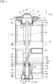
- FIG. 1 is a vertical cross-sectional view illustrating a first embodiment of an expansion valve according to the present invention.
- FIG. 2 is a vertical cross-sectional view of a main portion of an expansion valve according to the first embodiment.
- an expansion valve 10 includes a valve body 11, a power element 70, a valve element 40, a valve rod 60, a support member 100, a first vibration isolation spring 140, a coil spring 44, an adjusting screw 120 and a second vibration isolation spring 500.
- the valve body 11 is made of an aluminum alloy, for example, and can be obtained by subjecting the aluminum alloy or the like to extrusion molding with the X direction of FIG. 1 set as the extrusion direction, and then performing machining.
- the valve body 11 includes a power element mounting portion 12, which is an internal screw formed on an upper surface portion and engaged with an external screw 72a of the power element 70 to thereby fix the power element 70, an inlet port 20 through which a high-pressure refrigerant is introduced, an outlet port 28 through which the refrigerant flowing in from the inlet port 20 flows out, a return passage 30 of the refrigerant, a hole portion 33 to which the second vibration isolation spring 500 is attached, an internal screw 11a formed on a bottom side portion of the valve body 11, a mounting hole (or an internal screw for mounting) 80 for mounting the valve body 11 to an evaporator or other components not shown.
- the power element mounting portion 12 is formed as a bottomed cylindrical hole formed having a circular opening on an upper surface of the valve body 11 and having an internal screw formed on an inner wall surface thereof.
- An opening 32 that reaches (communicates with) the return passage 30 is formed at the center of the bottom portion of the hole.
- the center axis direction of the power element mounting portion 12 is a direction (the y direction) that is substantially orthogonal to the passing direction (X direction) of the refrigerant passing through the inside of the return passage 30.
- the internal screw 11a is formed so as to open on the lower side of the valve body 11, and an insertion hole 11b is formed on an upper portion thereof.
- a valve chamber 24 is formed in the inner side of the valve body 11.
- the valve chamber 24 has a cylindrical side wall surface, and the surface above the upper end of the inlet hole 20a is referred to as an upper wall surface 24a, and the surface below the lower end of the inlet hole 20a is referred to as a lower wall surface 24b.
- the vertical length of the upper wall surface 24a is sufficient to enable the first vibration isolation spring 140 described later to move in a sliding motion.
- the inlet port 20 is formed to communicate with the valve chamber 24 from the side of the valve chamber 24 via an inlet hole 20a having a smaller diameter than the inlet port 20.
- a narrow portion 28a having a smaller diameter than the outlet port 28 is provided behind the outlet port 28, and the narrow portion 28a is disposed above the valve chamber 24.
- the narrow portion 28a communicates with an upper end portion of the valve chamber 24 via a valve hole 26 that serves as an orifice.
- a valve seat 25 is formed on the valve chamber 24-side of the valve hole 26.
- a through hole 29 is formed vertically (the Y direction of FIG. 1 ) in the valve body 11 so as to communicate the return passage 30 with the narrow portion 28a.
- the valve hole 26, the through hole 29, the opening 32 and the valve chamber 24 are arranged so that their respective center axes are aligned in a straight line.
- the return passage 30 is formed further above the outlet port 28 in the valve body 11 and passes through the valve body 11 in a lateral direction (the X direction of FIG. 1 ). Further, a hole portion 33 that is coaxial with the through hole 29 and having a greater inner diameter than the through hole 29 is formed on a lower side of the return passage 30.
- the inlet port 20 and the outlet port 28 are opened on the right and left sides of the valve body 11, and similarly, the return passage 30 is formed to pass through the right and left sides of the valve body 11, the arrangement of the inlet port, the outlet port and both openings of the return passage can be changed arbitrarily depending on the layout of the refrigerant cycle in which the expansion valve is disposed.
- the outlet port 28 and the left side opening of the return passage 30 may be disposed to be opened to the front side or the back side of the drawing of FIG. 1 (that is, the inlet port and the outlet port may be arranged orthogonally when viewed from the center line of the valve rod 60, and similarly, both openings of the return passage may be arranged orthogonally).
- the power element 70 is composed of an upper lid member 71 and a receiving member 72 having a through port 72b formed at a center portion thereof, both of which are formed of stainless steel or the like, for example, a diaphragm 73 sandwiched between the upper lid member 71 and the receiving member 72, and a stopper member 90 disposed between the diaphragm 73 and the receiving member 72.
- a pressure operation chamber 75 is formed between the upper lid member 71 and the diaphragm 73, and after filling the pressure operation chamber 75 with a working gas, the chamber is sealed with a sealing plug 65.
- the lower portion of the receiving member 72 is cylindrical, and an external screw 72a is formed on the periphery thereof.
- the power element 70 is attached to the valve body 11 by screwing the external screw 72a into the internal screw (the internal screw opening on the upper surface of the valve body 11) of the power element mounting portion 12 via a packing 35.
- the valve element 40 is a spherical member that is disposed in the valve chamber 24 at a position opposed to the valve seat 25.
- the valve rod 60 is provided to pass through the valve hole 26, the through hole 29 and the opening 32 of the valve body 11, wherein an upper end of the valve rod 60 is abutted against a receiving portion 92 provided on a lower side of the stopper member 90 of the power element 70 and a lower end of the valve rod 60 is arranged to be in contact with the valve element 40.
- the second vibration isolation spring 500 is arranged in the hole portion 33 and elastically supports the valve rod 60. The details of the second vibration isolation spring 500 will be described later.
- the support member 100 is a member that supports the valve element 40 in the direction of the valve seat 25 (the direction of the valve rod 60). Although the valve element 40 is fixed to the support member 100, since the support member 100 is constantly pushed toward the direction of the valve seat 25 and the valve rod 60 by the coil spring 44, a configuration in which the support member 100 merely contacts against the valve element 40 may be utilized.
- the support member 100 includes a body portion 103, an upper surface portion 101 and a flange portion 102.
- An upper surface of the cylindrical body portion 103 has a conical recess and serves as the upper surface portion 101 that supports a lower surface of the valve element 40.
- the support member 100 includes a flange portion 102 that protrudes toward a lateral side (the outer circumferential side) from the body portion 103, and a lower surface of the flange portion 102 is configured to receive one end of the first vibration isolation spring 140 and the coil spring 44.
- an outer diameter of the body portion 103 below the flange portion 102 is configured to be smaller than an inner diameter of the coil spring 44, such that the body portion 103 fits inside the coil spring 44.
- the coil spring 44 is disposed between a lower surface of the flange portion 102 provided on the support member 100 and a concave portion 125 formed in the adjusting screw 120. Due to the elastic force of the coil spring 44, the valve element 40 is pushed toward the valve seat 25 via the support member 100.
- the first vibration isolation spring 140 is disposed between the lower surface of the flange portion 102 and the coil spring 44, the detailed configuration of which will be described later.
- the adjusting screw 120 includes a body portion 121, a hexagonal socket 122, an insertion portion 123, a leading edge portion 124, and the concave portion 125.
- the insertion portion 123 is formed above the body portion 121 with a smaller outer diameter than the body portion 121
- the leading edge portion 124 is formed above the insertion portion 123 with a smaller outer diameter than the insertion portion 123.
- the outer circumference of the body portion 121 is formed to be an external screw portion 121a designed to engage with the internal screw 11a formed on a lower side of the valve body 11.
- a concave portion 125 having a cylindrical space with the upper portion opened is provided on an upper portion of the adjusting screw 120.
- the concave portion 125 is formed to have a depth that reaches the vicinity of the body portion 121.
- the inner diameter of the concave portion 125 is designed to be slightly greater than the outer diameter of the coil spring 44, such that the coil spring 44 is stably disposed inside the concave portion 125.
- the hexagonal socket 122 that allows insertion of a hexagonal wrench (not shown) for turning the adjusting screw 120 is disposed at a lower portion of the adjusting screw 120 (the body portion 121).
- FIG. 3 is a perspective view illustrating the first vibration isolation spring 140 according to a first embodiment.
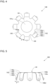
- FIG. 4 is a plan view illustrating the first vibration isolation spring 140 according to the first embodiment.
- FIG. 5 is a side view illustrating the first vibration isolation spring according to the first embodiment.
- the vibration isolation spring 140 includes a base portion 141 and a leg portion 142.
- the first vibration isolation spring 140 can be formed by press-forming a plate member having elasticity, such as stainless steel or an alloy thereof, for example.
- the base portion 141 is an annular plate-like member that forms an upper portion of the first vibration isolation spring 140 and includes a mounting hole 141a formed at the center thereof.
- a plurality of the leg portions 142 extend from an outer circumferential side of the base portion 141 in a direction perpendicular with respect to a tangent in the circumferential direction; that is to say, radially.
- eight leg portions 142 having the same lengths are provided at regular angular intervals.
- Each leg portion 142 is composed of an upper portion 142a, a bent portion 142b, a side portion 142c, and a projected portion 142d. The leg portions 142 are bent downward at the bent portion 142b.
- the upper portion 142a is formed substantially on the same plane as the base portion 141. Therefore, in the base portion of each of the leg portions 142, a cutout 145 having a predetermined shape is formed respectively on the side having the base portion 141.
- length C refers to the length of the upper portion 142a. Since the leg portions 142 include the upper portions 142a, the leg portions 142 are formed closer to a center side of the base portion 141 than the bent portions on the same plane as the base portion 141.
- the cutouts 145 formed between the side surfaces in the width direction of adjacent upper portions 142a are formed in an arc shape by continuously connecting base sides of the upper portions 142a with the same curvature, and as a result, the upper portions 142a (the leg portions 142) are smoothly connected to each other.
- the cutouts 145 may also be formed in a shape other than an arc-shape by connecting the base sides of the upper portions 142a with a different curvature.
- the bent portion 142b is formed continuously bending outward from the upper portion 142a toward the lower side (toward the coil spring 44).
- the bent portion 142b may be formed with a fixed curvature radius.
- the bent portion 142b is formed by bending the portion with a (90 - ⁇ ) degree bending process.
- the side portion 142c is formed in a straight line that extends continuously downward from the bent portion 142b.
- the angle of the side portion 142c is ⁇ degrees toward an outer downward direction with respect to the vertical direction.
- the projected portion 142d is formed outward in the vicinity of the lower end of the side portion 142c.
- the projected portion 142d may be formed as a part of a spherical surface, such as a hemispherical shape, or as portion of another curved surface.
- the projected portion 142d is mounted on the valve body 11, although the projected portion 142d elastically contacts a portion above the opening portion of the inlet hole 20a (the upper wall surface 24a), the dimensions of the respective portions are designed such that the projected portion 142d is not inserted into the opening of the inlet hole 20a even if the valve element 40 is positioned at a lowermost position.
- the vertical length of the leg portions 142 may be set to an arbitrary length as long as the lower edge portions of the leg portions 142 do not fall into the opening portion of the inlet hole 20a at the lowermost end of the vertical movement range of the first vibration isolation spring 140, in in order to prevent interference of the flow of refrigerant introduced from the inlet port 20, and in order to prevent drop of flow rate or occurrence of turbulence, it is preferable that the lower edge portion of the leg portions 142 does not reach the opening of the inlet hole 20a.
- the widths of the respective leg portions 142 are formed to be constant in each of the upper portion 142a, the bent portion 142b and the side portion 142c, the present invention is not restricted to this example, and narrowing or widening the width at the leading ends or other design modifications for most effectively suppressing the vibration of the valve element may be utilized.
- the thickness of the leg portions 142 (the thickness of the vibration isolation spring 140 in the case that the vibration isolation spring 140 is formed by press-forming a single elastic plate material) may be configured to a thickness that is suitable for suppressing the vibration of the valve element.
- a gap D ( FIG. 4 ) through which the refrigerant passes is formed between the respective adjacent leg portions 142.
- the outer diameter connected by the leading edge portions of the projected portion 142d of the first vibration isolation spring 140 is formed to be greater than the inner diameter of the upper wall surface 24a within the valve chamber 24, such that an elastic force acts when the first vibration isolation spring 140 is mounted, and the projected portions 142d are pressed against the upper wall surface 24a of the valve chamber 24.
- a space large enough for the coil spring 44 to be disposed therein is secured on the inner side of the leg portions 142.
- the first vibration isolation spring 140 when attaching the first vibration isolation spring 140, first, the first vibration isolation spring 140 is passed through the mounting hole 141a from the lower side to the body portion 103 of the support member 100, and the upper surface of the base portion 141 of the first vibration isolation spring 140 is brought into contact with the lower surface of the flange portion 102 of the support member 100. Next, the coil spring 44 is attached from the lower side of the first vibration isolation spring 140. In this state, the body portion 103 of the support member 100 is disposed on an inner side of the coil spring 44, and the upper surface of the coil spring 44 abuts against the lower surface of the base portion 141 of the first vibration isolation spring 140. In this way, the first vibration isolation spring 140 is disposed inside the valve chamber 24.
- the vibration isolation spring 140 is attached by being sandwiched between the flange portion 102 of the support member 100 and the coil spring 44 with a predetermined force. Then, in the vibration isolation spring 140, the projected portions 142d are pushed toward the upper wall surface 24a of the valve chamber 24 with a predetermined force due to the elastic force of the leg portions 142, and a sliding resistance is generated in accordance with the movement of the valve element 40.
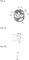
- FIG. 6 is a perspective view illustrating a second vibration isolation spring 500 of the first embodiment.
- FIG. 7A is a development front view of a main portion of the second vibration isolation spring according to the first embodiment.
- FIG. 7B is a cross-sectional view of a main portion of the second vibration isolation spring according to the present embodiment.
- FIG. 8 is a cross-sectional view illustrating a state in which a valve rod is attached to the second vibration isolation spring of the first embodiment.
- the second vibration isolation spring 500 is formed by bending a plate-like member into a cylindrical shape, as illustrated in FIG. 6 , and bending a first elastic piece 520, a second elastic piece 530 and a third elastic piece 540 inward.
- the first elastic piece 520, the second elastic piece 530 and the third elastic piece 540 are bent to inward, the first protruded contact portion 522, the second protruded contact portion 532 and the third protruded contact portion 542 are designed to be located at positions such that the circumference is equally divided.
- a diameter dimension of the circle connecting the tip portions of the first protruded contact portion 522, the second protruded contact portion 532 and the third protruded contact portion 542 are formed to have a smaller diameter than the valve rod 60.
- the second vibration isolation spring 500 can be formed by subjecting an elongated elastic metal plate to press working.
- a tongue piece 512 is provided at one end portion in the longitudinal direction of the elastic metal plate, and a tongue piece receiving portion 514 for receiving the tongue piece 512 when the elastic metal plate is bent into a cylindrical shape is formed at the other end portion.
- the protruded portion 516 is used, for example, when processing the elastic metal plate into a cylindrical shape.
- FIG. 7A is an explanatory partial view of the second vibration isolation spring 500 illustrating a state prior to bending the first elastic piece 520.
- FIG. 7B is a side view illustrating a main portion of the second vibration isolation spring 500 in a state prior to bending the first elastic piece 520.
- the second vibration isolation spring 500 is formed of a belt-shaped metal plate 500a having elasticity, on which a U-shaped first cutout portion 528 is punched out to form the first elastic piece 520, and the first protruded contact portion 522, which is a hemispherical-surface portion, is formed on a leading end portion thereof.
- the second elastic piece 530 and the third elastic piece 540 are configured by forming a second cutout portion 538 and a third cutout portion 548, and forming a second protruded contact portion 532 and a third protruded contact portion 542, which are hemispherical-surface portions, on the leading end thereof.
- the bases of the first, second and third elastic pieces 520, 530 and 540 are bent from one direction, and thereafter, as illustrated in FIG. 6 , the first, second and third elastic pieces 520, 530 and 540 are bent from the base portions such that the first, second and third protruded contact portions 522, 532 and 542 face inward.
- FIG. 8 is a plan view illustrating a state in which a valve rod 60 is inserted to a second vibration isolation spring 500 of the first embodiment.
- the valve rod 60 is supported by having protruded contact portions respectively formed on the leading edges of the three elastic pieces contact three areas of the circumference side surface of the valve rod 60 at even intervals.
- the number of elastic pieces may be set to an arbitrary number greater than or equal to 2.
- a high-pressure refrigerant discharged from a compressor flows from the inlet port 20 through the inlet hole 20a into the valve chamber 24, passes through the valve hole 26 and expands, and is subsequently sent out through the outlet port 28 to an evaporator (not shown).
- the refrigerant sent out from the evaporator enters from the left side entrance of the return passage 30, passes through the return passage 30 to exit from the right side exit and returns to the compressor. At this time, a portion of the refrigerant passing through the return passage 30 flows through the opening 32 to a lower portion of the power element 70.
- the temperature change of the refrigerant that flows to the lower portion of the power element 70 causes the pressure of the working gas inside the pressure operation chamber 75 to change accordingly.
- the stopper member 90 moves up and down in response to the movement of the diaphragm 73 that deformed according to the fluctuation of the internal pressure of the pressure operation chamber 75.
- the movement of the stopper member 90 is transmitted through the valve rod 60 to the valve element 40, and the flow rate of the expanded refrigerant is controlled.
- the first vibration isolation spring 140 moves together with the valve element 40 and the support member 100.
- the first vibration isolation spring 140 presses the upper wall surface 24a of the valve chamber 24 of the valve body 11 with a predetermined force
- a frictional force is generated between the projected portion 142d of the leg portions 242 and the upper wall surface 24a of the valve chamber 24.
- the valve element 40 and the support member 100 do not respond sensitively in the vertical direction due to the pressure fluctuation of the high-pressure refrigerant from the inlet port 20, and the vibration in the vertical direction can be prevented or reduced.
- the valve element 40 and the support member 100 do not move easily in the lateral direction opposing to the pressing force due to the pressure fluctuation of the high-pressure refrigerant from the inlet port 20, and they exert an effect of preventing vibration in the lateral direction. At the same time, the movement of the valve element 40 and the support member 100 in the vertical direction is guided.
- the leg portions 142 do not interfere with the inlet hole 20a, such that the flow rate and the occurrence of turbulence of the refrigerant can be suppressed and the passing noise of the refrigerant can be reduced.
- the first vibration isolation spring 140 is constituted by the radially extending leg portions 142, the vibration isolation spring can be easily attached in the valve body 11 by simple insertion through the opening portion of the internal screw 11a formed at the bottom portion of the valve body 11.
- the length of the leg portions 142 can be set to be greater than the height of the vibration isolation spring. Accordingly, the spring constant of the leg portions 142 can be reduced, and the change in force with respect to the deformation of the leg portions 142 can be made to be smaller, such that a more stable sliding resistance can be obtained. In addition, since the same widths are used for the leg portions 142, the calculation of the spring constant, that is, the design of the first vibration isolation spring 140, becomes easier.
- leg portions 142 are formed in a direction perpendicular (radial) with respect to a tangent in the circumferential direction of the base portion 141, the sliding resistance is generated without applying the torsional force of the base portion 141 in the circumferential direction.
- a second vibration isolation spring 500 that elastically supports the valve rod 60 is arranged in addition to the first vibration isolation spring 140, and the second vibration isolation spring 500 is configured to further provide a predetermined sliding friction in the driving direction of the valve rod 60. That is, even in cases where the vibration of the valve element 40 cannot be suppressed by the first vibration isolation spring 140 alone, it is possible to effectively suppress the vibration of the valve element 40 by additionally arranging the second vibration isolation spring 500.
- FIG. 9 is an upper view illustrating a first vibration isolation spring according to a second embodiment.
- the second embodiment has a configuration in which the first vibration isolation spring 140 of the first embodiment is replaced with a first vibration isolation spring 240, and since the rest of the configuration is the same as the first embodiment, a description of the shared elements is omitted.
- the first vibration isolation spring 240 includes a base portion 241 and a leg portion 242.
- the first vibration isolation spring 240 is formed by press-forming a plate member having elasticity, such as stainless steel or an alloy thereof, for example.
- the base portion 241 is an annular plate-like member that forms the upper portion of the first vibration isolation spring 240 and includes a mounting hole 141a formed at a center thereof, similar to the first embodiment.
- a plurality of the leg portions 242 extend from an outer circumferential side of the base portion 241 in a direction perpendicular with respect to a tangent in the circumferential direction; that is to say, radially.
- eight leg portions 242 having the same lengths are provided at regular angular intervals.
- Each leg portion 242 is composed of an upper portion 242a, a bent portion 142b, a side portion 142c and a projected portion 142d.
- the bent portion 142b, the side portion 142c and the projected portion 142d are the same as in the first embodiment.
- the first embodiment includes an arc-shaped cutout 145
- the second embodiment differs in that a substantially triangular cutout 245 is provided. Accordingly, the length E of the upper portion 242a according to the second embodiment is longer than the length C of the upper portion 142a of the first embodiment.
- the length of the leg portions 242 of the second embodiment is set to be longer in correspondence thereto.
- the outer circumference of the base portion 241 of the second embodiment is set to be smaller than the outer circumference of the base portion 141 of the first embodiment. It should be noted, in consideration of strength and stress concentration, small arc-shaped portions may be formed in the side surfaces of adjacent upper portions 242a in the width direction.
- the length of the first vibration isolation spring 240 can be further extended by forming the substantially triangular cutout 245. Accordingly, the spring constant of the leg portions 242 can be further reduced, the change in force of the leg portions 242 with respect to the deformation can be reduced, and a more stable sliding resistance can be achieved.
- FIG. 10 is a vertical cross-sectional view illustrating a third embodiment of the expansion valve according to the present invention.
- FIG. 11 is a perspective view illustrating a second vibration isolation spring according to the third embodiment.
- the third embodiment has a configuration in which the second vibration isolation spring 500 (where one row of a set of three elastic pieces is arranged) of the first embodiment is replaced with a second vibration isolation spring 600 (where two rows each having a set of three elastic pieces are arranged), and since the rest of the configuration is the same as the first embodiment, a description of the shared elements is omitted.
- the second vibration isolation spring 600 can be formed by subjecting an elongated elastic metal plate to press working.
- a tongue piece 612 is provided at one end portion in the longitudinal direction of the elastic metal plate, and a tongue piece receiving portion 614 for receiving the tongue piece 612 when the elastic metal plate is bent into a cylindrical shape is formed at the other end portion.
- the protruded portion 616 is used, for example, when processing the elastic metal plate into a cylindrical shape.
- each of the protruded contact portions (622, 626, 632, 636, 642, 646) which are hemispherical-surface portions, are formed at the leading edge portions of the respective elastic pieces (620, 624, 630, 634, 640, 644), and cutout portions (628, 638, 648) are formed in the longitudinal direction. Then, each elastic piece (620, 624, 630, 634, 640, 644) is bent inward.
- the number of elastic pieces may be selected from an arbitrary number of two or greater, as long as a plurality of elastic pieces are arranged in two rows at equal intervals on the circumferential side wall of the valve rod 60.
- the number of rows may also be greater than or equal to 2.
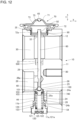
- FIG. 12 is a vertical cross-sectional view illustrating a fourth embodiment of an expansion valve not representing the present invention.
- the fourth embodiment has a configuration in which the first vibration isolation spring 140 of the first embodiment is replaced with a first vibration isolation spring 740, and since the rest of the configuration is the same as the first embodiment, a description of the shared elements is omitted.
- the first vibration isolation spring 740 includes a base portion and eight leg portions of the same length, , but the leg portions according to the fourth embodiment are longer than the first vibration isolation spring 140. That is, the leg portions of the first vibration isolation spring 140 is in contact with the upper wall surface 24a above the inlet hole 20a in the valve chamber 24, whereas the leg portions of the first vibration isolation spring 740 are in contact with a lower wall surface 24b. Then, in the first vibration isolation spring 740, the projected portions are pushed toward the lower wall surface 24b of the valve chamber 24 with a predetermined force due to the elastic force of the leg portions, and a sliding resistance is generated in accordance with the movement of the valve body 40.
- the length of the lower wall surface 24b in the vertical direction preferably has a length with enough thickness to provide the necessary strength between the upper portion of the insertion hole 11b and the inlet hole 20a, and should have a length in the vertical direction that is sufficient for the first vibration isolation spring 740 to move in a sliding motion.
- the present invention is not restricted to the embodiments described above, and various modifications are included in the scope of the invention defined by the appended claims.
- the present invention is not restricted to a configuration including all the components (structures) provided in the above-described embodiments.
- a portion of a configuration of one embodiment may be deleted or replaced with a configuration of another embodiment, or a configuration of one embodiment may be added to the configuration of another embodiment.
- the leg portions 142 and 242 are illustrated as having eight leg portions 142 of the same length provided at regular angular intervals. If the number of leg portions 142 and 242 is eight, it becomes possible to ensure stability of behavior and sliding restriction while maintaining balance of the gaps between the leg portions, but the present invention is not restricted to this example.
- the number of leg portions should merely be two or greater, and the lengths and angular intervals need not be the same.
- the leg portions illustrated in the above embodiments can have widths that vary along their length.
- the power element 70 illustrated in the embodiments is attached by screws, in addition to this, a configuration can be utilized in which a cylindrical portion is formed on an upper portion of the valve body, the power element 70 is inserted inside of the cylindrical portion, and caulking is performed on the inner side of the cylindrical portion to thereby attach the power element 70.
Landscapes
- Engineering & Computer Science (AREA)
- General Engineering & Computer Science (AREA)
- Mechanical Engineering (AREA)
- Physics & Mathematics (AREA)
- Thermal Sciences (AREA)
- Fluid Mechanics (AREA)
- Temperature-Responsive Valves (AREA)
- Lift Valve (AREA)
Applications Claiming Priority (2)
| Application Number | Priority Date | Filing Date | Title |
|---|---|---|---|
| JP2016156355A JP6697976B2 (ja) | 2016-08-09 | 2016-08-09 | 膨張弁 |
| PCT/JP2017/026433 WO2018030116A1 (ja) | 2016-08-09 | 2017-07-21 | 膨張弁 |
Publications (3)
| Publication Number | Publication Date |
|---|---|
| EP3499151A1 EP3499151A1 (en) | 2019-06-19 |
| EP3499151A4 EP3499151A4 (en) | 2020-04-08 |
| EP3499151B1 true EP3499151B1 (en) | 2025-06-18 |
Family
ID=61161979
Family Applications (1)
| Application Number | Title | Priority Date | Filing Date |
|---|---|---|---|
| EP17839189.2A Active EP3499151B1 (en) | 2016-08-09 | 2017-07-21 | Expansion valve |
Country Status (5)
| Country | Link |
|---|---|
| US (1) | US11009273B2 (https=) |
| EP (1) | EP3499151B1 (https=) |
| JP (1) | JP6697976B2 (https=) |
| CN (2) | CN115247915A (https=) |
| WO (1) | WO2018030116A1 (https=) |
Families Citing this family (5)
| Publication number | Priority date | Publication date | Assignee | Title |
|---|---|---|---|---|
| JP6789555B2 (ja) | 2017-07-12 | 2020-11-25 | 株式会社不二工機 | 膨張弁 |
| JP7165972B2 (ja) * | 2018-11-15 | 2022-11-07 | 株式会社不二工機 | 膨張弁 |
| JP7182283B2 (ja) * | 2019-11-25 | 2022-12-02 | 株式会社不二工機 | パワーエレメント及びこれを用いた膨張弁 |
| JP7619635B2 (ja) | 2022-02-07 | 2025-01-22 | 株式会社不二工機 | 膨張弁 |
| JP7774316B2 (ja) | 2023-02-09 | 2025-11-21 | 株式会社不二工機 | 膨張弁 |
Citations (1)
| Publication number | Priority date | Publication date | Assignee | Title |
|---|---|---|---|---|
| CN103075566A (zh) * | 2011-09-22 | 2013-05-01 | 株式会社不二工机 | 阀装置 |
Family Cites Families (20)
| Publication number | Priority date | Publication date | Assignee | Title |
|---|---|---|---|---|
| JPS60253773A (ja) * | 1984-05-31 | 1985-12-14 | カルソニックカンセイ株式会社 | 膨張弁 |
| JP3920059B2 (ja) * | 2001-09-17 | 2007-05-30 | 株式会社テージーケー | 膨張弁 |
| KR100463057B1 (ko) * | 2002-11-08 | 2004-12-23 | 현대자동차주식회사 | 에어컨 냉매의 유동 소음 저감장치 |
| JP4255892B2 (ja) * | 2003-11-06 | 2009-04-15 | 株式会社不二工機 | 膨張弁 |
| JP4666904B2 (ja) * | 2003-11-27 | 2011-04-06 | 株式会社不二工機 | 膨張弁 |
| JPWO2006090826A1 (ja) * | 2005-02-24 | 2008-07-24 | 株式会社不二工機 | 圧力制御弁 |
| JP4834391B2 (ja) * | 2005-12-01 | 2011-12-14 | 株式会社不二工機 | 膨張弁 |
| CN100582534C (zh) * | 2006-07-07 | 2010-01-20 | 浙江三花汽车控制系统有限公司 | 热力膨胀阀 |
| JP5991802B2 (ja) * | 2011-09-29 | 2016-09-14 | 株式会社不二工機 | 弁装置 |
| JP5933210B2 (ja) * | 2011-09-22 | 2016-06-08 | 株式会社不二工機 | 弁装置 |
| JP5906371B2 (ja) * | 2012-01-11 | 2016-04-20 | 株式会社テージーケー | 膨張弁および防振ばね |
| JP5974326B2 (ja) * | 2012-04-25 | 2016-08-23 | 株式会社テージーケー | 膨張弁および防振ばね |
| CN202630539U (zh) * | 2012-05-31 | 2012-12-26 | 宁波松鹰汽车部件有限公司 | 一种减振消噪的热力膨胀阀 |
| JP6143500B2 (ja) * | 2013-03-08 | 2017-06-07 | 株式会社不二工機 | 温度式膨張弁 |
| JP6142181B2 (ja) * | 2013-03-12 | 2017-06-07 | 株式会社テージーケー | 膨張弁および防振ばね |
| CN203743443U (zh) * | 2014-03-07 | 2014-07-30 | 奇瑞汽车股份有限公司 | 一种弹簧爪以及应用该种弹簧爪的膨胀阀 |
| JP6368895B2 (ja) * | 2014-10-01 | 2018-08-08 | 株式会社テージーケー | 制御弁 |
| US10436349B2 (en) | 2015-06-09 | 2019-10-08 | Denso Corporation | Pressure reduction valve |
| CN105485982B (zh) * | 2015-12-30 | 2018-04-06 | 浙江新劲空调设备有限公司 | 减振降噪膨胀阀 |
| CN205262003U (zh) * | 2015-12-30 | 2016-05-25 | 浙江新劲空调设备有限公司 | 降噪热力膨胀阀 |
-
2016
- 2016-08-09 JP JP2016156355A patent/JP6697976B2/ja active Active
-
2017
- 2017-07-21 EP EP17839189.2A patent/EP3499151B1/en active Active
- 2017-07-21 CN CN202210960291.3A patent/CN115247915A/zh active Pending
- 2017-07-21 WO PCT/JP2017/026433 patent/WO2018030116A1/ja not_active Ceased
- 2017-07-21 CN CN201780048787.0A patent/CN109564041A/zh active Pending
- 2017-07-21 US US16/322,960 patent/US11009273B2/en active Active
Patent Citations (1)
| Publication number | Priority date | Publication date | Assignee | Title |
|---|---|---|---|---|
| CN103075566A (zh) * | 2011-09-22 | 2013-05-01 | 株式会社不二工机 | 阀装置 |
Also Published As
| Publication number | Publication date |
|---|---|
| JP6697976B2 (ja) | 2020-05-27 |
| CN109564041A (zh) | 2019-04-02 |
| WO2018030116A1 (ja) | 2018-02-15 |
| US11009273B2 (en) | 2021-05-18 |
| JP2018025332A (ja) | 2018-02-15 |
| CN115247915A (zh) | 2022-10-28 |
| EP3499151A4 (en) | 2020-04-08 |
| US20190170411A1 (en) | 2019-06-06 |
| EP3499151A1 (en) | 2019-06-19 |
Similar Documents
| Publication | Publication Date | Title |
|---|---|---|
| EP3499151B1 (en) | Expansion valve | |
| US9702601B2 (en) | Expansion valve and vibration-proof spring | |
| US9909793B2 (en) | Expansion valve and vibration-proof spring | |
| EP3499150B1 (en) | Expansion valve | |
| JP4570473B2 (ja) | 弁装置および冷凍サイクル装置 | |
| US10190807B2 (en) | Expansion valve | |
| CN107314577B (zh) | 膨胀阀 | |
| CN103075566B (zh) | 阀装置 | |
| CN100394126C (zh) | 膨胀阀 | |
| EP3002531A1 (en) | Control valve | |
| CN107208819B (zh) | 节流装置以及冷冻循环系统 | |
| EP1275916B1 (en) | Expansion valve | |
| EP3133325A1 (en) | Control valve | |
| US7373788B2 (en) | Expansion valve | |
| JP6734595B2 (ja) | 膨張弁 | |
| JP4255892B2 (ja) | 膨張弁 | |
| KR20140076507A (ko) | 제어 밸브 | |
| JP6945249B2 (ja) | 膨張弁 | |
| JP6943379B2 (ja) | 膨張弁 | |
| JP6788887B2 (ja) | 膨張弁 | |
| JP2025064327A (ja) | 膨張弁 |
Legal Events
| Date | Code | Title | Description |
|---|---|---|---|
| STAA | Information on the status of an ep patent application or granted ep patent |
Free format text: STATUS: THE INTERNATIONAL PUBLICATION HAS BEEN MADE |
|
| PUAI | Public reference made under article 153(3) epc to a published international application that has entered the european phase |
Free format text: ORIGINAL CODE: 0009012 |
|
| STAA | Information on the status of an ep patent application or granted ep patent |
Free format text: STATUS: REQUEST FOR EXAMINATION WAS MADE |
|
| 17P | Request for examination filed |
Effective date: 20190205 |
|
| AK | Designated contracting states |
Kind code of ref document: A1 Designated state(s): AL AT BE BG CH CY CZ DE DK EE ES FI FR GB GR HR HU IE IS IT LI LT LU LV MC MK MT NL NO PL PT RO RS SE SI SK SM TR |
|
| AX | Request for extension of the european patent |
Extension state: BA ME |
|
| DAV | Request for validation of the european patent (deleted) | ||
| DAX | Request for extension of the european patent (deleted) | ||
| A4 | Supplementary search report drawn up and despatched |
Effective date: 20200305 |
|
| RIC1 | Information provided on ipc code assigned before grant |
Ipc: F16K 31/68 20060101ALI20200228BHEP Ipc: F16K 1/32 20060101ALI20200228BHEP Ipc: F25B 41/06 20060101AFI20200228BHEP |
|
| STAA | Information on the status of an ep patent application or granted ep patent |
Free format text: STATUS: EXAMINATION IS IN PROGRESS |
|
| 17Q | First examination report despatched |
Effective date: 20220520 |
|
| REG | Reference to a national code |
Ipc: F16K0001320000 Ref country code: DE Ref legal event code: R079 Ref document number: 602017090047 Country of ref document: DE Free format text: PREVIOUS MAIN CLASS: F25B0041060000 Ipc: F16K0001320000 |
|
| GRAP | Despatch of communication of intention to grant a patent |
Free format text: ORIGINAL CODE: EPIDOSNIGR1 |
|
| STAA | Information on the status of an ep patent application or granted ep patent |
Free format text: STATUS: GRANT OF PATENT IS INTENDED |
|
| RIC1 | Information provided on ipc code assigned before grant |
Ipc: F16K 31/68 20060101ALI20250114BHEP Ipc: F16K 1/32 20060101AFI20250114BHEP |
|
| INTG | Intention to grant announced |
Effective date: 20250204 |
|
| GRAS | Grant fee paid |
Free format text: ORIGINAL CODE: EPIDOSNIGR3 |
|
| GRAA | (expected) grant |
Free format text: ORIGINAL CODE: 0009210 |
|
| STAA | Information on the status of an ep patent application or granted ep patent |
Free format text: STATUS: THE PATENT HAS BEEN GRANTED |
|
| AK | Designated contracting states |
Kind code of ref document: B1 Designated state(s): AL AT BE BG CH CY CZ DE DK EE ES FI FR GB GR HR HU IE IS IT LI LT LU LV MC MK MT NL NO PL PT RO RS SE SI SK SM TR |
|
| REG | Reference to a national code |
Ref country code: GB Ref legal event code: FG4D |
|
| REG | Reference to a national code |
Ref country code: CH Ref legal event code: EP |
|
| REG | Reference to a national code |
Ref country code: DE Ref legal event code: R096 Ref document number: 602017090047 Country of ref document: DE |
|
| REG | Reference to a national code |
Ref country code: CH Ref legal event code: EP |
|
| REG | Reference to a national code |
Ref country code: IE Ref legal event code: FG4D |
|
| PG25 | Lapsed in a contracting state [announced via postgrant information from national office to epo] |
Ref country code: FI Free format text: LAPSE BECAUSE OF FAILURE TO SUBMIT A TRANSLATION OF THE DESCRIPTION OR TO PAY THE FEE WITHIN THE PRESCRIBED TIME-LIMIT Effective date: 20250618 |
|
| PGFP | Annual fee paid to national office [announced via postgrant information from national office to epo] |
Ref country code: DE Payment date: 20250730 Year of fee payment: 9 |
|
| REG | Reference to a national code |
Ref country code: LT Ref legal event code: MG9D |
|
| PG25 | Lapsed in a contracting state [announced via postgrant information from national office to epo] |
Ref country code: GR Free format text: LAPSE BECAUSE OF FAILURE TO SUBMIT A TRANSLATION OF THE DESCRIPTION OR TO PAY THE FEE WITHIN THE PRESCRIBED TIME-LIMIT Effective date: 20250919 Ref country code: NO Free format text: LAPSE BECAUSE OF FAILURE TO SUBMIT A TRANSLATION OF THE DESCRIPTION OR TO PAY THE FEE WITHIN THE PRESCRIBED TIME-LIMIT Effective date: 20250918 |
|
| PG25 | Lapsed in a contracting state [announced via postgrant information from national office to epo] |
Ref country code: BG Free format text: LAPSE BECAUSE OF FAILURE TO SUBMIT A TRANSLATION OF THE DESCRIPTION OR TO PAY THE FEE WITHIN THE PRESCRIBED TIME-LIMIT Effective date: 20250618 |
|
| PGFP | Annual fee paid to national office [announced via postgrant information from national office to epo] |
Ref country code: GB Payment date: 20250811 Year of fee payment: 9 |
|
| PG25 | Lapsed in a contracting state [announced via postgrant information from national office to epo] |
Ref country code: HR Free format text: LAPSE BECAUSE OF FAILURE TO SUBMIT A TRANSLATION OF THE DESCRIPTION OR TO PAY THE FEE WITHIN THE PRESCRIBED TIME-LIMIT Effective date: 20250618 |
|
| PGFP | Annual fee paid to national office [announced via postgrant information from national office to epo] |
Ref country code: FR Payment date: 20250804 Year of fee payment: 9 |
|
| PG25 | Lapsed in a contracting state [announced via postgrant information from national office to epo] |
Ref country code: RS Free format text: LAPSE BECAUSE OF FAILURE TO SUBMIT A TRANSLATION OF THE DESCRIPTION OR TO PAY THE FEE WITHIN THE PRESCRIBED TIME-LIMIT Effective date: 20250918 |
|
| PG25 | Lapsed in a contracting state [announced via postgrant information from national office to epo] |
Ref country code: LV Free format text: LAPSE BECAUSE OF FAILURE TO SUBMIT A TRANSLATION OF THE DESCRIPTION OR TO PAY THE FEE WITHIN THE PRESCRIBED TIME-LIMIT Effective date: 20250618 |
|
| PG25 | Lapsed in a contracting state [announced via postgrant information from national office to epo] |
Ref country code: NL Free format text: LAPSE BECAUSE OF FAILURE TO SUBMIT A TRANSLATION OF THE DESCRIPTION OR TO PAY THE FEE WITHIN THE PRESCRIBED TIME-LIMIT Effective date: 20250618 |
|
| PG25 | Lapsed in a contracting state [announced via postgrant information from national office to epo] |
Ref country code: PT Free format text: LAPSE BECAUSE OF FAILURE TO SUBMIT A TRANSLATION OF THE DESCRIPTION OR TO PAY THE FEE WITHIN THE PRESCRIBED TIME-LIMIT Effective date: 20251020 |
|
| REG | Reference to a national code |
Ref country code: AT Ref legal event code: MK05 Ref document number: 1804442 Country of ref document: AT Kind code of ref document: T Effective date: 20250618 |
|
| PG25 | Lapsed in a contracting state [announced via postgrant information from national office to epo] |
Ref country code: IS Free format text: LAPSE BECAUSE OF FAILURE TO SUBMIT A TRANSLATION OF THE DESCRIPTION OR TO PAY THE FEE WITHIN THE PRESCRIBED TIME-LIMIT Effective date: 20251018 |
|
| PG25 | Lapsed in a contracting state [announced via postgrant information from national office to epo] |
Ref country code: AT Free format text: LAPSE BECAUSE OF FAILURE TO SUBMIT A TRANSLATION OF THE DESCRIPTION OR TO PAY THE FEE WITHIN THE PRESCRIBED TIME-LIMIT Effective date: 20250618 Ref country code: SM Free format text: LAPSE BECAUSE OF FAILURE TO SUBMIT A TRANSLATION OF THE DESCRIPTION OR TO PAY THE FEE WITHIN THE PRESCRIBED TIME-LIMIT Effective date: 20250618 |
|
| PGFP | Annual fee paid to national office [announced via postgrant information from national office to epo] |
Ref country code: IT Payment date: 20251015 Year of fee payment: 9 |
|
| PG25 | Lapsed in a contracting state [announced via postgrant information from national office to epo] |
Ref country code: CZ Free format text: LAPSE BECAUSE OF FAILURE TO SUBMIT A TRANSLATION OF THE DESCRIPTION OR TO PAY THE FEE WITHIN THE PRESCRIBED TIME-LIMIT Effective date: 20250618 |
|
| PG25 | Lapsed in a contracting state [announced via postgrant information from national office to epo] |
Ref country code: PL Free format text: LAPSE BECAUSE OF FAILURE TO SUBMIT A TRANSLATION OF THE DESCRIPTION OR TO PAY THE FEE WITHIN THE PRESCRIBED TIME-LIMIT Effective date: 20250618 |
|
| PG25 | Lapsed in a contracting state [announced via postgrant information from national office to epo] |
Ref country code: EE Free format text: LAPSE BECAUSE OF FAILURE TO SUBMIT A TRANSLATION OF THE DESCRIPTION OR TO PAY THE FEE WITHIN THE PRESCRIBED TIME-LIMIT Effective date: 20250618 |
|
| PG25 | Lapsed in a contracting state [announced via postgrant information from national office to epo] |
Ref country code: SK Free format text: LAPSE BECAUSE OF FAILURE TO SUBMIT A TRANSLATION OF THE DESCRIPTION OR TO PAY THE FEE WITHIN THE PRESCRIBED TIME-LIMIT Effective date: 20250618 Ref country code: RO Free format text: LAPSE BECAUSE OF FAILURE TO SUBMIT A TRANSLATION OF THE DESCRIPTION OR TO PAY THE FEE WITHIN THE PRESCRIBED TIME-LIMIT Effective date: 20250618 |
|
| PG25 | Lapsed in a contracting state [announced via postgrant information from national office to epo] |
Ref country code: ES Free format text: LAPSE BECAUSE OF FAILURE TO SUBMIT A TRANSLATION OF THE DESCRIPTION OR TO PAY THE FEE WITHIN THE PRESCRIBED TIME-LIMIT Effective date: 20250618 |
|
| REG | Reference to a national code |
Ref country code: CH Ref legal event code: H13 Free format text: ST27 STATUS EVENT CODE: U-0-0-H10-H13 (AS PROVIDED BY THE NATIONAL OFFICE) Effective date: 20260224 |
|
| PG25 | Lapsed in a contracting state [announced via postgrant information from national office to epo] |
Ref country code: LU Free format text: LAPSE BECAUSE OF NON-PAYMENT OF DUE FEES Effective date: 20250721 |
|
| REG | Reference to a national code |
Ref country code: BE Ref legal event code: MM Effective date: 20250731 |
|
| PG25 | Lapsed in a contracting state [announced via postgrant information from national office to epo] |
Ref country code: MC Free format text: LAPSE BECAUSE OF FAILURE TO SUBMIT A TRANSLATION OF THE DESCRIPTION OR TO PAY THE FEE WITHIN THE PRESCRIBED TIME-LIMIT Effective date: 20250618 |
|
| PG25 | Lapsed in a contracting state [announced via postgrant information from national office to epo] |
Ref country code: DK Free format text: LAPSE BECAUSE OF FAILURE TO SUBMIT A TRANSLATION OF THE DESCRIPTION OR TO PAY THE FEE WITHIN THE PRESCRIBED TIME-LIMIT Effective date: 20250618 |
|
| PG25 | Lapsed in a contracting state [announced via postgrant information from national office to epo] |
Ref country code: BE Free format text: LAPSE BECAUSE OF NON-PAYMENT OF DUE FEES Effective date: 20250731 |
|
| PG25 | Lapsed in a contracting state [announced via postgrant information from national office to epo] |
Ref country code: CH Free format text: LAPSE BECAUSE OF NON-PAYMENT OF DUE FEES Effective date: 20250731 |
|
| PLBE | No opposition filed within time limit |
Free format text: ORIGINAL CODE: 0009261 |
|
| STAA | Information on the status of an ep patent application or granted ep patent |
Free format text: STATUS: NO OPPOSITION FILED WITHIN TIME LIMIT |
|
| REG | Reference to a national code |
Ref country code: CH Ref legal event code: L10 Free format text: ST27 STATUS EVENT CODE: U-0-0-L10-L00 (AS PROVIDED BY THE NATIONAL OFFICE) Effective date: 20260430 |