EP3499129A2 - Kochvorrichtung - Google Patents
Kochvorrichtung Download PDFInfo
- Publication number
- EP3499129A2 EP3499129A2 EP18212623.5A EP18212623A EP3499129A2 EP 3499129 A2 EP3499129 A2 EP 3499129A2 EP 18212623 A EP18212623 A EP 18212623A EP 3499129 A2 EP3499129 A2 EP 3499129A2
- Authority
- EP
- European Patent Office
- Prior art keywords
- cover body
- cooking
- cooking device
- cooker
- platform
- Prior art date
- Legal status (The legal status is an assumption and is not a legal conclusion. Google has not performed a legal analysis and makes no representation as to the accuracy of the status listed.)
- Withdrawn
Links
Images

Classifications
-
- A—HUMAN NECESSITIES
- A47—FURNITURE; DOMESTIC ARTICLES OR APPLIANCES; COFFEE MILLS; SPICE MILLS; SUCTION CLEANERS IN GENERAL
- A47J—KITCHEN EQUIPMENT; COFFEE MILLS; SPICE MILLS; APPARATUS FOR MAKING BEVERAGES
- A47J27/00—Cooking-vessels
- A47J27/08—Pressure-cookers; Lids or locking devices specially adapted therefor
-
- A—HUMAN NECESSITIES
- A47—FURNITURE; DOMESTIC ARTICLES OR APPLIANCES; COFFEE MILLS; SPICE MILLS; SUCTION CLEANERS IN GENERAL
- A47J—KITCHEN EQUIPMENT; COFFEE MILLS; SPICE MILLS; APPARATUS FOR MAKING BEVERAGES
- A47J43/00—Implements for preparing or holding food, not provided for in other groups of this subclass
- A47J43/04—Machines for domestic use not covered elsewhere, e.g. for grinding, mixing, stirring, kneading, emulsifying, whipping or beating foodstuffs, e.g. power-driven
- A47J43/044—Machines for domestic use not covered elsewhere, e.g. for grinding, mixing, stirring, kneading, emulsifying, whipping or beating foodstuffs, e.g. power-driven with tools driven from the top side
-
- F—MECHANICAL ENGINEERING; LIGHTING; HEATING; WEAPONS; BLASTING
- F24—HEATING; RANGES; VENTILATING
- F24C—DOMESTIC STOVES OR RANGES ; DETAILS OF DOMESTIC STOVES OR RANGES, OF GENERAL APPLICATION
- F24C11/00—Combinations of two or more stoves or ranges, e.g. each having a different kind of energy supply
-
- F—MECHANICAL ENGINEERING; LIGHTING; HEATING; WEAPONS; BLASTING
- F24—HEATING; RANGES; VENTILATING
- F24C—DOMESTIC STOVES OR RANGES ; DETAILS OF DOMESTIC STOVES OR RANGES, OF GENERAL APPLICATION
- F24C15/00—Details
- F24C15/10—Tops, e.g. hot plates; Rings
-
- F—MECHANICAL ENGINEERING; LIGHTING; HEATING; WEAPONS; BLASTING
- F24—HEATING; RANGES; VENTILATING
- F24C—DOMESTIC STOVES OR RANGES ; DETAILS OF DOMESTIC STOVES OR RANGES, OF GENERAL APPLICATION
- F24C15/00—Details
- F24C15/12—Side rests; Side plates; Cover lids; Splash guards; Racks outside ovens, e.g. for drying plates
-
- F—MECHANICAL ENGINEERING; LIGHTING; HEATING; WEAPONS; BLASTING
- F24—HEATING; RANGES; VENTILATING
- F24C—DOMESTIC STOVES OR RANGES ; DETAILS OF DOMESTIC STOVES OR RANGES, OF GENERAL APPLICATION
- F24C15/00—Details
- F24C15/14—Spillage trays or grooves
-
- F—MECHANICAL ENGINEERING; LIGHTING; HEATING; WEAPONS; BLASTING
- F24—HEATING; RANGES; VENTILATING
- F24C—DOMESTIC STOVES OR RANGES ; DETAILS OF DOMESTIC STOVES OR RANGES, OF GENERAL APPLICATION
- F24C7/00—Stoves or ranges heated by electric energy
- F24C7/08—Arrangement or mounting of control or safety devices
- F24C7/082—Arrangement or mounting of control or safety devices on ranges, e.g. control panels, illumination
- F24C7/086—Arrangement or mounting of control or safety devices on ranges, e.g. control panels, illumination touch control
Definitions
- the present invention relates to a cooking device, and specifically, to an embedded cooking device.
- Multifunctional cookers in current kitchens daily increase for example, an electric rice cooker, an electric stewpot, and an electric pressure cooker are independent, and are generally placed on a countertop or a cooking bench of a kitchen, and occupy kitchen space that is originally limited. Meanwhile, it also brings trouble to operation and oil cleaning aspects for users.
- the present invention provides a more simple and convenient cooking device.
- a cooking device comprising a cooktop body and a cooking platform, wherein an embedded cooker is disposed below the cooking platform, a cover body is disposed above the embedded cooker, wherein the cover body is transformed between a first position and a second position, wherein the cover body in the first position is in an opened state; and the cover body in the second position is in a closed state, and an upper surface of the cover body and an upper surface of the cooking platform are on a same horizontal plane.
- a multifunctional cooker is integrated on a cooking bench, and after being electrified, the embedded cooker can implement functions such as pan-frying, stir-frying, steaming, frying, boiling, and stewing or have some or all functions of an electric rice cooker, an electric stewpot, and an electric pressure cooker.
- the cooker is completely embedded below the cooking platform, and when the cover body is closed, the upper surface of the cover body and the upper surface of the cooking platform are on a same horizontal plane. In this way, cookers placed on a countertop of a kitchen can be reduced, and the kitchen can be maintained neat and nice, and is also easily cleaned.
- the cooking platform is further provided with an induction cooktop and/or a gas cooktop. In this way, other cooking requirements of users can also be ensured.
- the cooking device includes a control means and an operation panel, wherein the operation panel is disposed on the cooking platform, and the control means inputs a control instruction via the operation panel to control the embedded cooker and the cover body to work.
- the operation panel uses touch buttons to maintain a flat surface with a plane of the cooking platform.
- the cooking device includes a drive means for driving the cover body to be transformed between the first position and the second position; and a locking means for locking or unlocking the cover body in the second position, wherein the control means controls the locking means and the drive means to work.
- the cooking device includes an inner container, wherein an upper end of the inner container is placed on a support of an upper end of the embedded cooker; the support is provided with an opening, and a water collecting groove is disposed below the support; and a liquid substance spilled from the inner container during cooking enters the water collecting groove from the opening.
- the design can ensure that a substance generated during cooking such as moisture, foam, or oil is not spilled outside of the cooker, but enters the water collecting groove.
- the support is a detachable structure.
- the detachable support is convenient for cleaning or changing.
- the water collecting groove is connected to a discharge pipe, and the discharge pipe is connected to a sewerage system. Liquid substances overly accumulated are further discharged to a sewerage system of the kitchen, such as a sewer.
- the operation panel is provided with a slide trigger area, the slide trigger area sends an unlocking signal after being triggered, and after receiving the unlocking signal, the control means controls the locking means to unlock.
- the cooking device comprises a pressure relief means disposed on the cover body, in communication with an exhaust hole on the cover body.
- the cover body is provided with a sealing ring, and when the cover body is closed, the sealing ring closely fits in the support.
- the pressure in the cooker is too high, the pressure needs to be reduced by discharging gas, and after the pressure relief means is opened, the gas is discharged from the exhaust hole.
- the cooking device comprises a stirring apparatus, wherein the stirring apparatus has a drive member and a stirring member, the drive member driving the stirring member to rotate.
- the drive member is an electric drive means such as a motor, the stirring member may also be rotated by manually driving a rotating component. In this way, it can be ensured that food materials in the cooker can be stirred during cooking, so that the temperature of soup in the cooker is evenly distributed, the food materials are not easily burnt, nutrition of the materials is better released, and a boiling time is shortened and energy is saved.
- 1 is a cooking device
- 2 is a cooktop body
- 3 is a cooking platform
- 4 is an embedded cooker
- 5 is a cover body
- 6 is a control means
- 7 is an operation panel
- 8 is a drive means
- 9 is a locking means
- 10 is an inner container
- 11 is a support
- 12 is a discharge pipe
- 13 is a pressure relief means
- 14 is a stirring apparatus.
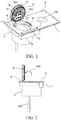
- FIG. 1 is a schematic structural diagram of a cooking device
- FIG. 2 is a schematic diagram of the cooking device when a cover body is in a first position
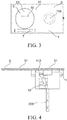
- FIG. 3 is a schematic diagram of a cooking platform when the cover body is in a second position
- FIG. 4 is a schematic diagram of a cooking device when the cover body is in the second position
- FIG. 5 is a schematic structural diagram of a support.
- the cooking device 1 has a cooktop body 2 and a cooking platform 3, and the cooking platform 3 may be further provided with an induction cooktop 100 and/or a gas cooktop 100.
- the combination design can ensure other cooking requirements of users.
- An embedded cooker 4 is disposed below the cooking platform 3, and after being electrified, the embedded cooker 4 can implement functions such as pan-frying, stir-frying, steaming, frying, boiling, and stewing or have some or all functions of an electric rice cooker, an electric stewpot, and an electric pressure cooker.
- a cover body 5 is disposed above the embedded cooker 4, and is connected to the cooktop body 2, and the cover body 5 is transformed between a first position P1 (vertical or slant position) and a second position P2 (horizontal position).
- the cover body 5 in the first position P1 is in an opened state; and the cover body 5 in the second position P2 is in a closed state, and an upper surface 51 of the cover body 5 and an upper surface 31 of the cooking platform 3 are on a same horizontal plane.
- the embedded cooker 4 is completely embedded below the cooking platform 3, and when the cover body 5 is closed, the upper surface 51 of the cover body 5 and the upper surface 31 of the cooking platform 3 are on a same horizontal plane. In this way, cookers placed on a countertop of a kitchen can be reduced, and the kitchen is maintained neat and nice, and is also easily cleaned.
- the cooking device 1 further includes a control means 6 and an operation panel 7, where the operation panel 7 is disposed on the cooking platform 3, and the control means 6 inputs a control instruction via the operation panel 7 to control the embedded cooker 4 and the cover body 5 to work.
- the operation panel 7 uses touch buttons to maintain a flat surface with a plane of the cooking platform 3.
- the cooking device 1 further includes a drive means 8 for driving the cover body 5 to be transformed between the first position P1 and the second position P2; and a locking means 9 for locking or unlocking the cover body 5 in the second position P2.
- the control means 6 controls the locking means 9 and the drive means 8 to work.
- the operation panel 7 is provided with a slide trigger area 70, the slide trigger area 70 sends an unlocking signal after being triggered, and after receiving the unlocking signal, the control means 6 controls the locking means 9 to unlock.
- the cooking device 1 includes an inner container 10, wherein an upper end of the inner container 10 is placed on a support 11 of an upper end of the embedded cooker 4; the support 11 is provided with an opening 111, and a water collecting groove 112 is disposed below the support 11; and a liquid substance spilled from the inner container 10 during cooking enters the water collecting groove 112 from the opening 111.
- the design can ensure that a substance generated during cooking such as moisture, foam, or oil is not spilled outside of the cooker, but enters the water collecting groove.
- the support 11 is a detachable structure convenient for cleaning or changing.
- the water collecting groove 112 is connected to a discharge pipe 12, and the discharge pipe 12 is connected to a sewerage system 200. Liquid substances overly accumulated are further discharged to a sewerage system of the kitchen, such as a sewer.
- the cooking device 1 includes a pressure relief means 13 disposed on the cover body 5, is communication with an exhaust hole 50 on the cover body 5.
- the cover body 5 is provided with a sealing ring, and when the cover body is closed, the sealing ring closely fits in the support 11.
- the pressure relief means 13 is opened, the gas is discharged from the exhaust hole 50.
- the cooking device 1 includes a stirring apparatus 14, the stirring apparatus 14 has a drive member 141 and a stirring member 142, and the drive member drives the stirring member 142 to rotate.
- the drive member 141 is an electric drive means such as a motor
- the stirring member 142 may also be rotated by manually driving a rotating component. In this way, it can be ensured that food materials in the cooker can be stirred during cooking, so that the temperature of soup in the cooker is evenly distributed, the food materials are not easily burnt, nutrition of the materials is better released, and a boiling time is shortened and energy is saved.
Landscapes
- Engineering & Computer Science (AREA)
- Mechanical Engineering (AREA)
- Chemical & Material Sciences (AREA)
- Combustion & Propulsion (AREA)
- General Engineering & Computer Science (AREA)
- Food Science & Technology (AREA)
- Frying-Pans Or Fryers (AREA)
- Electric Ovens (AREA)
- Cookers (AREA)
Applications Claiming Priority (1)
| Application Number | Priority Date | Filing Date | Title |
|---|---|---|---|
| CN201721768236.5U CN208339363U (zh) | 2017-12-15 | 2017-12-15 | 炊具 |
Publications (2)
| Publication Number | Publication Date |
|---|---|
| EP3499129A2 true EP3499129A2 (de) | 2019-06-19 |
| EP3499129A3 EP3499129A3 (de) | 2019-09-25 |
Family
ID=64665645
Family Applications (1)
| Application Number | Title | Priority Date | Filing Date |
|---|---|---|---|
| EP18212623.5A Withdrawn EP3499129A3 (de) | 2017-12-15 | 2018-12-14 | Kochvorrichtung |
Country Status (2)
| Country | Link |
|---|---|
| EP (1) | EP3499129A3 (de) |
| CN (1) | CN208339363U (de) |
Families Citing this family (2)
| Publication number | Priority date | Publication date | Assignee | Title |
|---|---|---|---|---|
| CN112113249A (zh) * | 2019-06-21 | 2020-12-22 | 广东美的厨房电器制造有限公司 | 集成厨具 |
| DE102019210395A1 (de) * | 2019-07-15 | 2021-01-21 | BSH Hausgeräte GmbH | Gargerätevorrichtung |
Citations (5)
| Publication number | Priority date | Publication date | Assignee | Title |
|---|---|---|---|---|
| US2217804A (en) * | 1939-01-28 | 1940-10-15 | Gen Motors Corp | Domestic appliance |
| DE4406108A1 (de) * | 1994-02-25 | 1995-08-31 | Dieter Brodthage | Spülmulden-Kochcenter für den privaten Haushalt |
| JP2010175100A (ja) * | 2009-01-28 | 2010-08-12 | Panasonic Corp | 加熱調理器 |
| WO2013006981A1 (de) * | 2011-07-13 | 2013-01-17 | Tipper Tie Alpina Gmbh | Bedienvorrichtung mit berührungsempfindlichem bildschirm |
| EP3671042A1 (de) * | 2017-08-16 | 2020-06-24 | LG Electronics Inc. -1- | Heizgerät und kochvorrichtung damit |
Family Cites Families (9)
| Publication number | Priority date | Publication date | Assignee | Title |
|---|---|---|---|---|
| US3102533A (en) * | 1961-02-02 | 1963-09-03 | Jenn Air Products Company Inc | Counter-top range exhaust apparatus |
| JPS5869328A (ja) * | 1981-10-21 | 1983-04-25 | Matsushita Electric Ind Co Ltd | こんろ |
| IT238833Y1 (it) * | 1995-02-01 | 2000-11-15 | Zanussi Elettrodomestici | Piano di cottura a scomparsa |
| CN1526991A (zh) * | 2003-03-04 | 2004-09-08 | 庆 徐 | 组合式电灶具 |
| JP2008025943A (ja) * | 2006-07-24 | 2008-02-07 | Rinnai Corp | コンロ |
| CN102589021A (zh) * | 2012-02-19 | 2012-07-18 | 林庆森 | 燃气灶上进风式碟形节能锅架 |
| CN203215768U (zh) * | 2013-03-16 | 2013-09-25 | 绍兴县滨海合力厨房用品设计中心 | 一种集成灶 |
| KR101614089B1 (ko) * | 2014-11-13 | 2016-04-20 | 정원식 | 인덕션 조리기 |
| CN204629644U (zh) * | 2015-05-14 | 2015-09-09 | 浙江潮邦厨具电器有限公司 | 一种集成灶的翻盖机构 |
-
2017
- 2017-12-15 CN CN201721768236.5U patent/CN208339363U/zh not_active Expired - Fee Related
-
2018
- 2018-12-14 EP EP18212623.5A patent/EP3499129A3/de not_active Withdrawn
Patent Citations (5)
| Publication number | Priority date | Publication date | Assignee | Title |
|---|---|---|---|---|
| US2217804A (en) * | 1939-01-28 | 1940-10-15 | Gen Motors Corp | Domestic appliance |
| DE4406108A1 (de) * | 1994-02-25 | 1995-08-31 | Dieter Brodthage | Spülmulden-Kochcenter für den privaten Haushalt |
| JP2010175100A (ja) * | 2009-01-28 | 2010-08-12 | Panasonic Corp | 加熱調理器 |
| WO2013006981A1 (de) * | 2011-07-13 | 2013-01-17 | Tipper Tie Alpina Gmbh | Bedienvorrichtung mit berührungsempfindlichem bildschirm |
| EP3671042A1 (de) * | 2017-08-16 | 2020-06-24 | LG Electronics Inc. -1- | Heizgerät und kochvorrichtung damit |
Also Published As
| Publication number | Publication date |
|---|---|
| CN208339363U (zh) | 2019-01-08 |
| EP3499129A3 (de) | 2019-09-25 |
Similar Documents
| Publication | Publication Date | Title |
|---|---|---|
| CN105361435A (zh) | 一种多功能餐桌 | |
| CN203969676U (zh) | 智能餐饮系统 | |
| MX2009001474A (es) | Aparato de coccion, en particular un aparato casero de coccion. | |
| CN108115700A (zh) | 一种全自动智能炒菜机器人 | |
| EP3499129A2 (de) | Kochvorrichtung | |
| JP2009006049A (ja) | システムキッチン | |
| CN106889868B (zh) | 一种具有分格轮佐料添加机构的多功能炒菜机 | |
| US8616121B1 (en) | Cooktop drain | |
| CN112178714B (zh) | 多功能集成厨房加工平台及其控制方法 | |
| CN109363487B (zh) | 烹饪电器 | |
| CN204930796U (zh) | 一种多功能餐桌 | |
| JP2009011401A (ja) | システムキッチン | |
| CN210354406U (zh) | 一种通配式烹饪器具 | |
| CN203935020U (zh) | 一种多功能平底锅 | |
| CN103892690A (zh) | 具有电动旋动煮饺装置的电饭锅 | |
| CN206675275U (zh) | 一种可移动的智能整体厨房 | |
| CN212521563U (zh) | 一种远程控制的多功能厨电系统 | |
| CN105394947A (zh) | 具备微波烹饪功能的嵌入式消毒柜及橱柜 | |
| JP5002179B2 (ja) | システムキッチン | |
| CN211427087U (zh) | 厨房电器控制装置 | |
| US20200056789A1 (en) | Arrangement for Regulating a Cooking Operation | |
| KR200473042Y1 (ko) | 일체형 복합 주방가전기기 | |
| CN209744437U (zh) | 一种烹饪智能炉灶 | |
| CN111110011B (zh) | 轻便型直流电充电式自动炒锅 | |
| KR102773562B1 (ko) | 원격제어가 가능한 인덕션 복합 조리설비 |
Legal Events
| Date | Code | Title | Description |
|---|---|---|---|
| PUAI | Public reference made under article 153(3) epc to a published international application that has entered the european phase |
Free format text: ORIGINAL CODE: 0009012 |
|
| STAA | Information on the status of an ep patent application or granted ep patent |
Free format text: STATUS: THE APPLICATION HAS BEEN PUBLISHED |
|
| AK | Designated contracting states |
Kind code of ref document: A2 Designated state(s): AL AT BE BG CH CY CZ DE DK EE ES FI FR GB GR HR HU IE IS IT LI LT LU LV MC MK MT NL NO PL PT RO RS SE SI SK SM TR |
|
| AX | Request for extension of the european patent |
Extension state: BA ME |
|
| PUAL | Search report despatched |
Free format text: ORIGINAL CODE: 0009013 |
|
| AK | Designated contracting states |
Kind code of ref document: A3 Designated state(s): AL AT BE BG CH CY CZ DE DK EE ES FI FR GB GR HR HU IE IS IT LI LT LU LV MC MK MT NL NO PL PT RO RS SE SI SK SM TR |
|
| AX | Request for extension of the european patent |
Extension state: BA ME |
|
| RIC1 | Information provided on ipc code assigned before grant |
Ipc: F24C 15/14 20060101ALI20190819BHEP Ipc: F24C 15/12 20060101AFI20190819BHEP Ipc: F24C 7/00 20060101ALN20190819BHEP |
|
| STAA | Information on the status of an ep patent application or granted ep patent |
Free format text: STATUS: REQUEST FOR EXAMINATION WAS MADE |
|
| 17P | Request for examination filed |
Effective date: 20200325 |
|
| RBV | Designated contracting states (corrected) |
Designated state(s): AL AT BE BG CH CY CZ DE DK EE ES FI FR GB GR HR HU IE IS IT LI LT LU LV MC MK MT NL NO PL PT RO RS SE SI SK SM TR |
|
| STAA | Information on the status of an ep patent application or granted ep patent |
Free format text: STATUS: EXAMINATION IS IN PROGRESS |
|
| 17Q | First examination report despatched |
Effective date: 20210618 |
|
| GRAP | Despatch of communication of intention to grant a patent |
Free format text: ORIGINAL CODE: EPIDOSNIGR1 |
|
| STAA | Information on the status of an ep patent application or granted ep patent |
Free format text: STATUS: GRANT OF PATENT IS INTENDED |
|
| RIC1 | Information provided on ipc code assigned before grant |
Ipc: F24C 7/00 20060101ALN20241015BHEP Ipc: A47J 43/044 20060101ALI20241015BHEP Ipc: F24C 15/10 20060101ALI20241015BHEP Ipc: F24C 11/00 20060101ALI20241015BHEP Ipc: A47J 27/08 20060101ALI20241015BHEP Ipc: F24C 15/14 20060101ALI20241015BHEP Ipc: F24C 15/12 20060101AFI20241015BHEP |
|
| RIC1 | Information provided on ipc code assigned before grant |
Ipc: F24C 7/08 20060101ALI20241021BHEP Ipc: A47J 43/044 20060101ALI20241021BHEP Ipc: F24C 15/10 20060101ALI20241021BHEP Ipc: F24C 11/00 20060101ALI20241021BHEP Ipc: A47J 27/08 20060101ALI20241021BHEP Ipc: F24C 15/14 20060101ALI20241021BHEP Ipc: F24C 15/12 20060101AFI20241021BHEP |
|
| INTG | Intention to grant announced |
Effective date: 20241105 |
|
| STAA | Information on the status of an ep patent application or granted ep patent |
Free format text: STATUS: THE APPLICATION IS DEEMED TO BE WITHDRAWN |
|
| 18D | Application deemed to be withdrawn |
Effective date: 20250306 |