EP3498904B1 - Overlocknähmaschine - Google Patents
Overlocknähmaschine Download PDFInfo
- Publication number
- EP3498904B1 EP3498904B1 EP17838961.5A EP17838961A EP3498904B1 EP 3498904 B1 EP3498904 B1 EP 3498904B1 EP 17838961 A EP17838961 A EP 17838961A EP 3498904 B1 EP3498904 B1 EP 3498904B1
- Authority
- EP
- European Patent Office
- Prior art keywords
- cover
- looper
- state
- shaft
- detection
- Prior art date
- Legal status (The legal status is an assumption and is not a legal conclusion. Google has not performed a legal analysis and makes no representation as to the accuracy of the status listed.)
- Active
Links
Images


Classifications
-
- D—TEXTILES; PAPER
- D05—SEWING; EMBROIDERING; TUFTING
- D05B—SEWING
- D05B57/00—Loop takers, e.g. loopers
- D05B57/06—Loop takers, e.g. loopers for overedge-stitch sewing machines
-
- D—TEXTILES; PAPER
- D05—SEWING; EMBROIDERING; TUFTING
- D05B—SEWING
- D05B73/00—Casings
- D05B73/005—Doors or covers for accessing inner parts of the machine; Security devices therefor
-
- D—TEXTILES; PAPER
- D05—SEWING; EMBROIDERING; TUFTING
- D05B—SEWING
- D05B57/00—Loop takers, e.g. loopers
- D05B57/30—Driving-gear for loop takers
- D05B57/34—Driving-gear for loop takers in overedge-stitch sewing machines
-
- D—TEXTILES; PAPER
- D05—SEWING; EMBROIDERING; TUFTING
- D05B—SEWING
- D05B63/00—Devices associated with the loop-taker thread, e.g. for tensioning
-
- D—TEXTILES; PAPER
- D05—SEWING; EMBROIDERING; TUFTING
- D05B—SEWING
- D05B63/00—Devices associated with the loop-taker thread, e.g. for tensioning
- D05B63/02—Loop-taker thread take-up levers
-
- D—TEXTILES; PAPER
- D05—SEWING; EMBROIDERING; TUFTING
- D05B—SEWING
- D05B63/00—Devices associated with the loop-taker thread, e.g. for tensioning
- D05B63/04—Loop-taker thread guards
-
- D—TEXTILES; PAPER
- D05—SEWING; EMBROIDERING; TUFTING
- D05B—SEWING
- D05B69/00—Driving-gear; Control devices
- D05B69/36—Devices for stopping drive when abnormal conditions occur, e.g. thread breakage
-
- D—TEXTILES; PAPER
- D05—SEWING; EMBROIDERING; TUFTING
- D05B—SEWING
- D05B73/00—Casings
- D05B73/04—Lower casings
-
- D—TEXTILES; PAPER
- D05—SEWING; EMBROIDERING; TUFTING
- D05B—SEWING
- D05B87/00—Needle- or looper- threading devices
- D05B87/02—Needle- or looper- threading devices with mechanical means for moving thread through needle or looper eye
Definitions
- the present invention relates to an overlock sewing machine.
- a technique has been disclosed in Japanese Patent Application Laid Open No. 2013-063221 and Japanese Patent Application Laid Open No. 2014-018292 listed below for an overlock sewing machine in which looper threading is supported by a pump driving operation, and a main shaft for sewing is driven by a single motor using clutch switching.
- This technique prevents abnormal switching in such an overlock sewing machine between the threading state and the sewing state.
- the technique is supported by providing separate respective switches, i.e., a switch used to detect the open/closed state of a looper cover or the like and a switch used to detect the switching between the looper threading state and the sewing-enabled state.
- an overlock sewing machine described in JP 2013-063221 and JP 2014-018292 employs multiple switches. This involves complicated wiring, and leads to an increased cost.
- an overlock sewing machine includes other kinds of covers such as a side cover or the like in addition to the looper cover. Accordingly, the overlock sewing machine is preferably configured to require only a single switch to detect the open/closed state of the looper cover and the side cover and to detect the threading switching state.
- JP2016137028 in the name of the present applicant, discloses an overlock sewing machine which a discrimination ring is provided on a main shaft fixing operating shaft, provided swingably in a prescribed range so as to be stopped at a permission position in a state in which the rotation of a main shaft is permitted, and be located at a swing position displaced from the permission position in a state in which the rotation of the main shaft is not permitted. Accordingly, a common structure for detecting the opening/closing of a looper cover is partly changed, thereby providing an overlock sewing machine with a simple structure in which a single microswitch enables the detection of switching between a threading state and a sewing state and the detection of the opening/closing of the looper cover.
- JPH0938369 in the name of the present applicant, discusses a method and apparatus in which, when a louver cover is opened to pass a string through a louver or to do an inspection or adjustment of the louver, electricity to a drive control circuit of a motor for driving a sewing machine is turned off, and threading work or inspection work can be carried out with a sense of security.
- a cloth table of a sewing machine or louver cover
- a first operation axis is moved to the right by the action of a spring mounted to an axial part of the axis and an operation arm provided on the axis moves in the axial direction of the axis so as to be spaced apart from a microswitch.
- an OFF signal is outputted from the microswitch and a drive stop signal is outputted from a motor drive circuit to stop a sewing machine motor. It is indicated by a stop state indicating means based on the OFF signal that the cover is opened so that the motor is stopped.
- a stop state indicating means based on the OFF signal that the cover is opened so that the motor is stopped.
- JPH07303784 discusses providing a safety device for a sewing machine which is intended to detecting the opening/closing of plural covers with detector.
- the device is provided with a detecting means consisting of one detector arranged at a position where the opening of the plural covers of the sewing machine can be detected, and a control means which performs such control to stop the operation of the sewing machine when the fact that either of the plural covers is set in an open state is detected by the detecting means.
- JPH0570483U discloses a safety device for an overlock sewing machine intended to eliminate the risk of the overlock sewing machine being driven with its internal mechanism exposed.
- the present invention provides an overlock sewing machine comprising: a threading mechanism configured to perform threading of a looper; a switching mechanism configured to switch the threading mechanism between a threading state and a sewing-enabled state; a looper cover coupled with a hinge shaft having an axial direction extending in a width direction of the overlock sewing machine on a front side of the threading mechanism such that it can be opened and closed, and configured to cover at least a part of the looper at a closed position; a side cover provided on one side of the hinge shaft with respect to the looper cover, and coupled with a sewing machine main body such that it can be opened and closed; a switch including an operation protrusion, and configured such that, when the operation protrusion is pressed, a motor configured to drive a main shaft is switched from a driving-disabled state to a driving-enabled state; and a detection lever configured to press the operation protrusion, and configured such that, when the switching mechanism is switched to the sewing-enabled state in a state
- the detection lever In a non-operation state, the detection lever is positioned at an initial position at which it does not press the operation protrusion.
- the detection lever When the detection lever is operated in a state in which the side cover is set to a closed position, the detection lever is set to an operation-enabled position at which the detection lever presses the operation protrusion.
- the detection lever When the detection lever is operated in a state in which the side cover is set to an open position, the detection lever is set by passing through the operation-enabled position to an operation-disabled position at which the detection lever does not press the operation protrusion.
- the overlock sewing machine may further comprise: a looper cover open/closed state detection shaft configured such that it extends in a direction in parallel with the hinge shaft, and such that, when it is moved toward one side along the hinge axis, it comes in contact with the detection lever so as to operate the detection lever; and a pressing portion provided to the looper cover, and configured such that, when the looper cover is slid toward the one side along the axial direction of the hinge shaft in a state in which the looper cover is set to the closed position, the pressing portion presses the looper cover open/closed state detection shaft.
- the side cover When the detection lever is operated in a state in which the side cover is set to the closed position, the side cover directly or otherwise indirectly operates the looper cover so as to provide positioning restriction of the pressing portion such that the detection lever is maintained at the operation-enabled position.
- the detection lever When the detection lever is operated in a state in which the side cover is set to the open position, the side cover is located away from the looper cover such that the positioning restriction of the pressing portion is released, thereby setting the detection lever to the operation-disabled position.
- the overlock sewing machine may further comprise: a detection lever spring that applies a force to the detection lever such that it is set to the initial position from the operation-enabled position or otherwise the operation-disabled position; a cover detection shaft spring that applies a force to the looper cover open/closed state detection shaft toward the other side in the axial direction; and a looper cover spring that applies a force to the looper cover such that the looper cover is moved toward the one side in the axial direction of the hinge shaft against the force applied by the cover detection shaft spring and the force applied by the detection lever spring in a state in which the looper cover is set to the closed position, so as to move the detection lever from the initial position to the operation-enabled position or otherwise to the operation-disabled position.
- a detection lever spring that applies a force to the detection lever such that it is set to the initial position from the operation-enabled position or otherwise the operation-disabled position
- a cover detection shaft spring that applies a force to the looper cover open/closed
- the overlock sewing machine may further comprise: a swing lever portion configured to be swingable in a predetermined range such that, when rotation of the main shaft is enabled, the swing lever portion is positioned at an enabled position in a stationary state, and when the rotation of the main shaft is disabled, the swing lever portion is set to a swing position displaced from the enabled position; and an operation restricting portion configured such that, when the swing lever portion is set to the enabled position, the operation of the detection lever is enabled, and such that, when the swing lever portion is not set to the enabled position, the operation of the detection lever is restricted.
- the switch may be fixed to a sewing machine main body.
- the overlock sewing machine may further comprises a blade cover provided together with the looper cover such that the blade cover can be opened and closed, and configured to cover at least a part of a cutting mechanism configured to cut a sewing target.
- the blade cover is configured such that it can be moved in a direction along the axial direction of the hinge shaft independent of the looper cover according to a cutoff width adjustment amount set for the cutting mechanism.
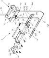
- the overlock sewing machine 1 is configured including a looper unit A, an air flow path switching mechanism B, a threading switching mechanism C, a main shaft fixing mechanism D, and a safety mechanism E. Furthermore, as shown in Fig. 11 , the overlock sewing machine 1 includes a looper cover 110 configured as a front portion of the overlock sewing machine 1 and configured to operate the safety mechanism E, a blade cover 120, and a side cover 130 that forms a left-side portion of the overlock sewing machine 1. Furthermore, the overlock sewing machine 1 includes a cover position switching mechanism F configured to switch the left-right position of the looper cover 110 in its closed state according to the open/closed state of the side cover 130.
- the air flow path switching mechanism B and the threading switching mechanism C form a "threading mechanism” configured to support looper threading using aerodynamic force.
- the threading switching mechanism C and the main shaft fixing mechanism D form a “switching mechanism” configured to switch the threading mechanism between the threading state and the sewing-enabled state. Description will be made regarding each of the mechanisms.
- the looper unit A is arranged on the left side of a unit base 142 that forms part of a sewing machine main body 140 (see Fig. 9 ).
- the looper unit A includes an upper looper 10 and a lower looper 12 each of which is configured to have an approximately longitudinal and hollow structure.
- the upper looper 10 and the lower looper 12 have their end portions respectively configured as an upper looper inlet 10A and a lower looper inlet 12A, and have their tip portions respectively configured as an upper looper blade tip 10B and a lower looper blade tip 12B.
- the looper unit A is configured to allow the upper looper inlet 10A and the lower looper inlet 12A to receive an upper looper thread TH1 and a lower looper thread TH2 transferred via the airflow path switching mechanism B and the threading switching mechanism C.
- the looper unit A includes a looper balance 14.
- the looper balance 14 includes an upper looper thread hook 14A and a lower looper thread hook 14B.
- the air flow path switching mechanism B includes an approximately block-shaped main body 16.
- the main body 16 is fixed on the front side of the unit base 142.
- a tube 19 is arranged on the back face of the main body 16.
- the air flow path switching mechanism B is configured such that the compressed air generated by a compressed air supply apparatus (not shown) is supplied to the air flow path switching mechanism B via the tube 19.
- an upper looper thread insertion opening 16A and a lower looper thread insertion opening 16B are formed on the upper face of the main body 16.
- the upper looper thread insertion opening 16A and the lower looper thread insertion opening 16B are configured such that they respectively communicate with an upper looper thread discharging tube 16C and a lower looper thread discharging tube 16D.
- a selection knob 18 is provided on the front face of the main body 16.
- the air flow path switching mechanism B is configured to allow the user to operate the selection knob 18 to select the thread to be threaded from among the upper looper thread TH1 and the lower looper thread TH2.
- the threading switching mechanism C is arranged below the air flow path switching mechanism B.
- the threading switching mechanism C includes a tube support member 20.
- the tube support member 20 is configured to have an approximately U-shaped structure having an opening facing the front side.
- the tube support member 20 is fixedly mounted on the unit base 142 (see Fig. 1 ) by screws.
- the threading switching mechanism C includes a pair of slide tubes 22 arranged in parallel in the front-back direction, each extending in the left-right direction. The left-end portions of the slide tubes 22 are respectively slidably inserted into support holes 20A and 20B formed in the left-side wall of the tube support member 20.
- an upper looper conducting tube 32 and a lower looper conducting tube 34 are slidably inserted into the right ends of the respective slide tubes 22.
- the left-side ends of the upper looper conducting tube 32 and the lower looper conducting tube 34 are held by the right-side wall of the tube support member 20.
- the upper-end portions of the upper looper conducting tube 32 and the lower looper conducting tube 34 are coupled to the upper looper thread discharging tube 16C and the lower looper thread discharging tube 16D, respectively.
- a flange 22A is formed on the right-side end of each slide tube 22.
- a slide plate (slide member) 24 is arranged on the right side of the tube support member 20 such that its thickness direction matches the front-back direction and such that it extends in the left-right direction.
- the slide plate 24 has a left-side end portion configured as a holding portion 24L.
- the holding portion 24L is configured to have an approximately U-shaped structure having an opening facing the front side.
- the holding portion 24L is arranged within a space defined by the tube support member 20.
- the slide tubes 22 are slidably held by U-shaped groves 24A formed in the holding portion 24L.
- the flange 22A of each slide tube 22 is arranged on the inner side of the holding portion 24L.
- a slide tube spring 26 configured as a compression coil spring is mounted on the right-end portion of each slide tube 22.
- Each slide tube spring 26 is arranged between the flange 22A and the right wall of the holding portion 24L. This allows each slide tube 22 to be moved between the threading position and the sewing-enabled position according to the sliding of the slide plate 24 in the left-right direction.
- the left ends of the slide tubes 22 are respectively coupled to the upper looper inlet 10A and the lower looper inlet 12A.
- the left ends of the slide tubes 22 are moved toward the right side away from the upper looper inlet 10A and the lower looper inlet 12A.
- a slot 24B and an irregularly shaped slot 24C are formed in the slide plate 24 such that they have their longitudinal axes in the left-right direction and such that they are arranged in parallel along the left-right direction.
- the irregularly shaped slot 24C is arranged on the right side of the slot 24B.
- the irregularly shaped slot 24C is configured to have a slot portion 24C1 having a constant width and an approximately circular expended-diameter portion 24C2 coupled to the left-side end of the slot portion 24C1 and having a diameter that is larger than the width of the slot portion 24C1.
- a pin 24D is monolithically provided to the right-side end of the slide plate 24 so as to form a single unit such that it protrudes toward the front side.
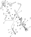
- a support shaft 28 is arranged above the aforementioned slide tubes 22 such that its axis extends in the left-right direction and such that it passes through both the left wall and the right wall of the tube support member 20. Furthermore, the support shaft 28 is arranged such that it passes through the holding portion 24L. In this state, the holding portion 24L is held so as to be slidable along the support shaft 28. Furthermore, a shaft spring 30 (see Fig. 2 ) configured as a compression coil spring is mounted on the right-side portion of the support shaft 28. The shaft spring 30 applies a force to the holding portion 24L of the slide plate 24 toward the left side with respect to the tube support member 20.
- a slide plate support 36 is provided on the right side of the tube support member 20 and on the back side of the slide plate 24.
- the slide plate support 36 is fixed to the unit base 142 by screws.
- the slide plate support 36 is configured to have an approximately longitudinal plate structure extending in the left-right direction.
- the right-side portion of the slide plate support 36 is configured to have an approximately U-shaped structure having an opening facing the front side as viewed in a plan view.
- a pair of left and right pins 36P are provided to the left-side portion of the slide plate support 36 such that they protrude toward the front side.
- the pair of pins 36P are respectively inserted into the slot 24B and the slot portion 24C1 of the slide plate 24 such that the slide plate 24 is slidable.
- An operation shaft 38 is arranged such that its axis extends in the left-right direction and such that it passes through the right-side portion (U-shaped curved portion) of the slide plate support 36.
- the operation shaft 38 is arranged such that it passes through through holes 36A and 36B formed in the slide plate support 36.
- the operation shaft 38 is rotatably held by the slide plate support 36.
- a switching member (switching restricting portion) 40 is fixed to the operation shaft 38 on the left side with respect to the right wall of the slide plate support 36 so as to be swingable (turnable) together with the operation shaft 38.
- An arm is formed at the right-end portion of the switching member 40 such that it extends toward the upper side.
- a pin 40P is provided to the tip of the arm such that it protrudes toward the right side. The pin 40P is inserted into an arc-shaped curved slot 36C formed in the right wall of the slide plate support 36 so as to be slidable.
- the switching member 40 has an engagement pin 40A extending toward the front side.
- a switching operation member (main shaft fixing operation arm portion) 42 is fixed to the operation shaft 38 on the right side with respect to the central side wall of the slide plate 36 so as to be swingable (turnable) together with the operation shaft 38.
- the switching operation member 42 has an arm extending toward the lower side.
- a pin 42P is provided to the tip of the arm such that it protrudes toward the right side.
- One end of an operation spring 44 configured as a torsion spring is engaged with the pin 42P.
- the other end of the operation spring 44 is engaged with a small hole 36D formed in the slide plate support 36.
- an engagement slot 42A is formed as a through hole in the upper-end portion of the switching operation member 42 such that its longitudinal direction matches the upper-lower direction.
- the switching linkage member 48 is provided on the front side of the slide plate support 36. As shown in Fig. 4 , the switching linkage member 48 has a boss 48A having an approximately cylindrical shape. The boss 48A is rotatably supported by a support shaft 46 fixed to the unit base 142 such that its axis extends along the front-back direction. With such an arrangement, the switching linkage member 48 is interposed in the front-back direction between a reception member 50 fixed to the support shaft 46 and an E-ring 52 engaged with the support shaft 46.
- the switching linkage member 48 includes a switching arm (slide member engagement portion) 48B and a pair of engagement arms (switching engagement portions) 48C and 48D.
- the switching arm 48B is provided such that it extends from the boss 48A toward the upper side.
- the tip of the switching arm 48B is arranged adjacent to the left side of the pin 24D (see Fig. 1 ) of the slide plate 24 described above.
- the engagement arm 48C is provided such that it extends from an intermediate portion in the longitudinal direction of the switching arm 48B in an approximately diagonally upper-right direction.
- the engagement arm 48D is provided at a position below the engagement arm 48C such that it extends from an intermediate portion in the longitudinal direction of the switching arm 48B toward the right side.
- the engagement pin 40A (see Fig. 1 ) of the switching member 40 described above is arranged between the pair of engagement arms 48C and 48D.
- a switching knob (switching operation portion) 54 is fixed to the boss 48A of the switching engagement member 48 such that it and the boss 48A can be swung (turned) as a single unit.
- the switching arm 48B presses the pin 24D of the slide plate 24 toward the right side, thereby sliding the slide plate 24 toward the right side.
- the switching knob 54 is arranged on the front side of a front cover 146 (see Fig. 6 ) described later so as to allow the user to operate the switching knob 54. Furthermore, as shown in Fig.
- a looper balance guide 56 is arranged at the left end of the threading switching mechanism C.
- the looper balance guide 56 is fixed to the sewing machine main body 140 (described later) or the unit base 142.
- a pair of round holes 56A and 56B are formed in the looper balance guide 56 such that their positions correspond to the support holes 20A and 20B of the tube support member 20.
- the main shaft fixing mechanism D includes an approximately cylindrical-shaped outer-side fixing shaft (first shaft) 60 having a bottom face and an opening facing the back side with its axial direction as the front-back direction.
- the outer-side fixing shaft 60 is inserted into an insertion hole 142A formed in the unit base 142.
- An internal-side fixing shaft (second shaft) 62 is inserted into the internal space of the outer-side fixing shaft 60 such that they can be moved relative to each other.
- a shaft spring 64 configured as a compression coil spring is inserted into the internal space of the outer-side fixing shaft 60 such that it is interposed between the bottom portion (front-end portion) of the outer-side fixing shaft 60 and the inner-side fixing shaft 62.
- the shaft spring 64 applies a force so as to move the outer-side fixing shaft 60 and the inner-side fixing shaft 62 away from each other in opposite directions.
- a coupling pin 66 is fixed to the front end of the inner-side fixing shaft 62.
- the coupling pin 66 is arranged such that it extends from the inner-side fixing shaft 62 toward the right side, and such that it is inserted into a slot (engagement portion) 60A formed such that it extends in the front-back direction in the outer circumferential portion of the outer-side fixing shaft 60.
- the coupling pin 66 is engaged with the back end of the slot 60A by the force applied by the shaft spring 64. In this state, the relative position between the inner-side fixing shaft 62 and the outer-side fixing shaft 60 is maintained.
- the right end of the coupling pin 66 is inserted into the engagement slot 42A of the switching operation member 42 described above (see Fig. 3B ).
- the inner-side fixing shaft 62 is coupled to the switching operation member 42 by the coupling pin 66.
- this arrangement allows the inner-side fixing shaft 62 and the coupling pin 66 to be moved in the front-back direction.
- the outer-side fixing shaft 60 is positioned within the expanded-diameter portion 24C2 of the slide plate 24. Furthermore, a groove portion 60B is formed over the overall circumference of the outer circumferential portion of the front end of the outer-side fixing shaft 60. The inner edge of the slot 24C1 of the slide plate 24 is inserted into the groove portion 60B so as to allow the slide plate 24 to be slid toward the left side. This arrangement allows the slide plate 24 to be slid to the threading position.
- the main shaft 68 is arranged on the back side of the outer-side fixing shaft 60 such that its axis extends in the left-right direction.
- the main shaft 68 is configured such that it can be rotated by rotationally driving a flywheel 144 (see Fig. 11 ) provided on the right-side portion of the overlock sewing machine 1.
- An approximately diskshaped main shaft fixing plate 69 is fixed to the main shaft 68.
- the main shaft fixing plate 69 is arranged such that it is aligned with the axial line of the outer-side fixing shaft 60.
- a notch 69A is formed in the outer-circumferential portion of the main shaft fixing plate 69 such that it has an opening facing the outer side along the radial direction of the main shaft fixing plate 69.
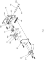
- the safety mechanism E is arranged on the right side with respect to the threading switching mechanism C described above.
- the safety mechanism E is configured including a judgment ring 72, a cover detection base 74, a detection lever 76, a looper cover open/closed state detection shaft 80 (which will simply be referred to as the "cover detection shaft 80" hereafter), a switch 84, and a switch base 86.
- the judgment ring 72 is configured to have an approximately cylindrical shape. Furthermore, the judgment ring 72 is fixed to the operation shaft 38 such that it can be rotated together with the operation shaft 38 as a single unit on the right side of the slide plate support 36.
- a notch 72A is formed in the outer circumferential portion of the judgment ring 72 such that it has an opening facing the outer side in the radial direction of the judgment ring 72.
- the notch 72A is formed to have an opening that passes through in the axial direction of the judgment ring 72.
- the judgment ring 72 by turning the judgment ring 72 together with the operation shaft 38 as a single unit, this changes the turn position of the notch 72A, thereby controlling the operation of the detection lever 76 (allowing or restricting the operation of the detection lever 76). That is to say, depending on the swing position of the operation shaft 38, the judgment ring 72 and a first lever portion 76C of the detection lever 76 function as an operation restricting portion which restricts the operation of the detection lever 76.
- the operation shaft 38, the switching member 40, the switching operation member 42, and the judgment ring 72 form the swing lever portion. Also, a part of or otherwise all of the components may be monolithically formed as a single unit so as to form such a swing lever portion.
- the cover detection base 74 is arranged on a diagonally lower-right side of the judgment ring 72 (see Fig. 1 ), and is fixed to the unit base 142 by screws.
- a support shaft 74A is provided to an approximately central portion of the cover detection base 74 such that it protrudes toward the front side.
- the detection lever 76 has a cylindrical-shaped boss 76B having a support hole 76A in its central portion.
- the support shaft 74A of the cover detection base 74 is inserted into the support hole 76A so as to support the boss 76B (detection lever 76) such that it is turnable (swingable) around the support shaft 74A. That is to say, the turn axis of the detection lever 76 crosses the axis (left-right direction) of the operation shaft 38 described above.
- a detection lever spring 78 configured as a torsion spring is mounted on the rear-end portion of the boss 76B. The detection lever spring 78 applies a force to the detection lever 76 in the clockwise direction as viewed from the front side.
- the detection lever 76 includes a first lever portion 76C extending toward the upper side from the boss 76B, an operation arm 76D extending toward the front side from the left-side face of an intermediate portion in the longitudinal direction of the first lever portion 76C, a second lever portion 76E extending from the boss 76B toward a diagonally lower-right side so as to press an operation protrusion 84A of a switch 84 described later, and a stopper 76F formed in an intermediate portion in the longitudinal direction of the first lever portion 76C such that it protrudes toward the right side.
- the notch 72A of the aforementioned judgment ring 72 is positioned on the left side (enabled position) of the first lever portion 76C. In this state, the judgment ring 72 does not restrict the swinging of the first lever portion 76C toward the left side (the detection lever 76 is set to the operation enabled state).
- the notch 72A of the judgment ring 72 is displaced in the circumferential direction of the judgment ring 72 with respect to the tip portion of the first lever portion 76C (set to the swing position). In this state, the judgment ring 72 restricts the swinging of the first lever portion 76C toward the left side (the detection lever 76 is set to the operation restricted state).
- the stopper 76F of the detection lever 76 is pressed in contact with a left-side arm 74B of the cover detection base 74 by the force applied by the detection lever spring 78, thereby maintaining the detection lever 76 at its initial position.
- the cover detection shaft 80 is arranged adjacent to the right side of the operation arm 76D of the detection lever 76 such that the axial direction of the cover detection shaft 80 extends along the left-right direction (see Fig. 1 ). Furthermore, the cover detection shaft 80 is inserted into a pair of through holes 74C formed in the cover detection base 74 so as to be slidable. Furthermore, a force-applying spring 82 (cover detection shaft spring) configured as a compression coil spring is mounted on the left-side portion of the cover detection shaft 80. The right end of the force-applying spring 82 is engaged with an E-ring 83 fixed to the cover detection shaft 80.
- the force-applying spring 82 applies a force to the cover detection shaft 80 toward the right side (in a direction away from the detection lever 76).
- the detection lever 76 operates (swings around the axis of the support shaft 74A).
- the switch 84 is arranged on the right side of the detection lever 76 (second lever portion 76E), and is fixed to the switch base 86 described later by screws.
- the switch 84 includes an operation protrusion 84A.
- the switch 84 operates. Specifically, when the operation protrusion 84A is pressed by the detection lever 76 (second lever portion 76E) such that it retracts, the switch 84 is set to the on state, and the motor is set to a state in which driving is enabled. Conversely, when the operation protrusion 84A is not pressed by the detection lever 76 (second lever portion 76E) and it protrudes, the switch 84 is set to the off state, and the motor is set to a state in which driving is disabled.
- the switch base 86 is formed of an insulating material, and is fixed to the cover detection base 74 by screws. Accordingly, the aforementioned switch 84 is fixed to the unit base 142 via the cover detection base 74. Accordingly, the switch 84 is fixed to a member that is stationary when the looper cover 110 or the side cover 130 described later is opened or closed. It should be noted that, in a case in which an insulation state is secured for the switch 84 and a terminal thereof, such a switch base 86 may be omitted.
- the second lever portion 76E (the tip thereof) of the detection lever 76 retracts (has a distance) with respect to the operation protrusion 84A of the switch 84 toward the lower side (non-operating range). That is to say, the motor is set to the driving-disabled state. Furthermore, the detection lever 76 is designed to provide two functions that are switched according to the pressing amount applied to the detection lever 76 by the cover detection shaft 80.
- the detection lever 76 is designed such that, when the pressing amount applied to the detection lever 76 by the cover detection shaft 80 matches a predetermined amount, the detection lever 76 rotates from the initial position in a counterclockwise direction around the axis of the support shaft 74A such that it is moved (driven) to an operation-enabled position at which the second lever portion 76E presses the operation protrusion 84A of the switch 84.
- the motor comes to be in a state in which it can be driven.
- the detection lever 76 further rotates beyond the operation-enabled position.
- the second lever portion 76E is positioned away from the operation protrusion 84A (this position will be referred to as the "operation-disabled position" hereafter).
- the detection lever 76 when the pressing force applied to the detection lever 76 by the cover detection shaft 80 is released, the detection lever 76 is turned (returned) to the initial position from the operation-enabled position or otherwise the operation-disabled position by the force applied by the detection lever spring 78.
- the cover position switching mechanism F is configured including a hinge mechanism 90 that couples the looper cover 110 with the overlock sewing machine 1 via a hinge, and a side cover open/closed state detection shaft 100 (which will simply be referred to as the "cover detection shaft 100" hereafter).
- the hinge mechanism 90 is configured including a pair of left and right fixed hinge portions 92L 92R arranged at the lower-end portion of the front cover 146 arranged on the front side of the overlock sewing machine 1, a hinge shaft 94 arranged such that its axis extends in the left-right direction (width direction), and a hinge spring 96 configured as a compression coil spring.
- the front cover 146 covers the threading switching mechanism C, the main shaft fixing mechanism D, and the safety mechanism E, described above, from the front side.
- the looper cover 110 is provided on the front side of the front cover 146 in order to cover a part of the aforementioned looper portion A.
- the looper cover 110 is configured such that it can be opened and closed with respect to the front cover 146 by the hinge mechanism 90.
- the looper cover 110 includes a cover portion 110A configured to cover the front cover 146.
- the rear-end portion of the looper cover 110 has an extension that extends toward the left side with respect to the cover portion 110A.
- the extension will be referred to as an "extension portion 110B".
- the cover portion 110A is structured such that the left-side portion of the cover portion 110A is cut out.
- a pair of left and right hinge portions 110L and 110R are provided on the rear-end portion of the looper cover 110.
- the hinge portions 110L and 110R are arranged on the right side with respect to the extension portion 110B such that there is a distance between them in the left-right direction.
- the pair of left and right fixed hinge portions 92L and 92R are arranged such that there is a distance between them in the left-right direction, and such that they are arranged between the pair of hinge portions 110L and 110R of the looper cover 110. Furthermore, the hinge shaft 94 is slidably held by the pair of fixed hinge portions 92L and 92R. Furthermore, the pair of hinge portions 110L and 110R of the looper cover 110 are held by the hinge shaft 94 so as to be rotatable and slidable in the left-right direction. Moreover, a notch 93 is formed in the left-side fixed hinge portion 92L such that it has an opening facing the lower side.
- the shaft length of the hinge shaft 94 is designed such that it corresponds to the left-right length of the rear-end portion of the looper cover 110 in the open state thereof. That is to say, the hinge shaft 94 is designed to have a shaft length that is larger than the length between the pair of hinge portions 110L and 110R. The hinge shaft 94 is arranged such that it extends toward the left side with respect to the hinge portion 110L.
- the hinge spring (looper cover spring) 96 is mounted on (fitted to) the right-side portion of the hinge shaft 94. With such an arrangement, the hinge spring 96 is mounted in a state in which its shape is compressed and changed between an E-ring 97 engaged with the hinge shaft 94 on the left side of the fixed hinge portion 92R and the fixed hinge portion 92R. In this state, the hinge spring 96 applies a force to the hinge shaft 94 toward the left side. Furthermore, another E-ring 97 is engaged with the hinge shaft 94 on the right side of the hinge portion 110L of the looper cover 110. With this arrangement, the E-ring 97 is pressed in contact with the hinge portion 110L by the hinge shaft 94 pressed toward the left side, which applies a force to the looper cover 110 toward the left side.
- a rib 110C monolithically provided to the looper cover 110 is arranged on the right side with respect to the fixed hinge portion 92L.
- the rib 110C in the open state of the looper cover 110, the rib 110C is in contact with the fixed hinge portion 92L, which restricts the movement of the looper cover 110 toward the left side.
- the rib 110C in the closed state in which the looper cover 110 covers the front cover 146, the rib 110C is positioned on the right side of the notch 93 of the hinge portion 92L. In this state, the position restriction for the looper cover 110 provided by the rib 110C is disabled.
- a hook (pressing portion) 110D is monolithically provided to the right-side wall of the looper cover 110.
- the hook 110D is configured such that it protrudes from the right-side wall toward the left side.
- the looper cover 110 is slid toward the left side by the force applied by the hinge spring 96, and the rib 110C is inserted into the notch 93 of the hinge structure 90. Furthermore, the hook 110D of the looper cover 110 is inserted into the window 146A (see the arrow K2 shown in Fig. 9 ) such that it is engaged with the window 146A. In this state, this arrangement prevents the looper cover 110 from turning toward the front side and from coming to be in the open state. That is to say, with such an arrangement, the looper cover 110 is maintained at the closed position.
- the right-side face of the looper cover 110 and a right-side face of the sewing machine main body cover 158 are positioned at a closed position so as to form a single face (this closed position of the looper cover 110 will be referred to as the "normal closed state” hereafter). Furthermore, when the looper cover 110 is slid toward the left side by the force applied by the hinge spring 96, the looper cover 110 is configured such that its hook 110D presses a right end 80A of the cover detection shaft 80 toward the left side.
- the blade cover 120 is arranged on the left side of the looper cover 110 (specifically, the cover portion 110A).
- the blade cover 120 includes a pair of left and right hinge portions 120L and 120R to be coupled with the hinge shaft 94 via hinges.
- the hinge portions 120L and 120R are held by the hinge shaft 94 (the left-side portion thereof) so as to be rotatable and slidable in the left-right direction. That is to say, the hinge shaft 94 is configured as a common rotational shaft for the looper cover 110 and the blade cover 120.
- a blade cover spring 98 configured as a compression coil spring is mounted on (fitted to) the left-side portion of the hinge shaft 94 such that it is interposed between the pair of hinge portions 120L and 120R of the blade cover 120.
- the right end of the blade cover spring 98 is engaged with the E-ring 97 fixed to the hinge shaft 94.
- the blade cover spring 98 applies a force to the blade cover 120 toward the left side.
- a hook 120A is formed on the right-side portion of blade cover 120 such that it protrudes toward the right side.
- the hook 120A is inserted from the left side into an approximately U-shaped guide 110E formed in the left-side portion of the looper cover 110 so as to be slidable.
- the blade cover 120 is turned together with the looper cover 110 such that they cover a lower blade 150 and an upper blade 152 (see Fig. 11 ) from the front side.
- the blade cover 120 is turned to the closed position together with the looper cover 110, the blade cover 120 is slid toward the left side along the hinge shaft 94.
- a left end 120B of the blade cover 120 comes in contact with the lower blade 150 or otherwise a support member for supporting the lower blade 150, thereby restricting the sliding of the blade cover 120 toward the left side.
- a step portion 120C is formed in the blade cover 120 along the edge of the left-side portion (cut-out portion) of the looper cover 110.
- the step portion 120C is formed such that, in a state in which the hook 120A of the blade cover 120 is inserted into the guide 110E of the looper cover 110, the surface (front face in the closed state) of the blade cover 120 and the surface (front face) of the looper cover 110 form a single face.
- the cover detection shaft 100 is arranged such that it extends axially in the left-right direction.
- the cover detection shaft 100 is arranged on the left side of the hinge shaft 94 (see Fig. 11 ) such that they are coaxially arranged.
- the cover detection shaft 100 is inserted into a through hole 140A formed in the sewing machine main body 140 so as to be slidable.
- the cover detection shaft 100 is configured such that its right end comes in contact with the left end of the hinge shaft 94.
- the left-side portion of the cover detection shaft 100 is arranged such that it protrudes toward the left side with respect to the sewing machine main body 140.
- a detection spring 102 configured as a compression coil spring is mounted on the left-side portion of the cover detection shaft 100 (see Fig. 9 ).
- the detection spring 102 is arranged between an E-ring 104 engaged with the left-end portion of the cover detection shaft 100 and the sewing machine main body 140, and presses the cover detection shaft 100 toward the left side.
- an E-ring 106 is engaged with the right-end portion of the cover detection shaft 100. By engaging the E-ring 106 with the sewing machine main body 140, the position of the cover detection shaft 100 is maintained. The position of the cover detection shaft 100 in this state will be referred to as an "open-state detection position".
- a reception plate 154 is provided on the left side of the sewing machine main body 140 such that it is arranged above the cover detection shaft 100.
- the reception plate 154 is formed in an approximately hat-shaped structure having an opening facing the right side as viewed in a plan view. Both ends of the reception plate 154 formed along its longitudinal direction are fixed to the sewing machine main body 140 by screws.
- the side cover 130 is formed in an approximately box-shaped structure having an opening facing the right side.
- the side cover 130 is arranged on the left side with respect to the looper cover 110 (one of both sides of the hinge shaft 94 along its axial direction).
- the opening portion formed as the rear wall of the side cover 130 is fixed to the sewing machine main body 140 via a hinge member 156.
- the side cover 130 is fixed to the sewing machine main body 140 such that it can be opened and closed with the upper-lower direction as the axial direction.
- an opening portion is formed in the upper wall of the side cover 130, which is configured as a storage portion 130A having an opening facing the right side.
- a needle plate 153 of the sewing machine main body 140 is stored in the storage portion 130A.
- an engagement member 132 is fixed to the left-side wall of the side cover 130.
- the engagement member 132 is formed in an approximately inverted-L-shaped structure as viewed from the front side.
- the lower portion of the engagement member 132 is fixed to a pair of upper and lower fixing portions 130B formed in the side cover 130 by screws.
- a hook portion 132A is formed at an end of the upper-end side of the engagement member 132 such that it protrudes toward the upper side.
- an approximately cylindrical stopper 130C is formed on the left-side wall of the side cover 130 such that it is positioned above the fixing portions 130B.
- an approximately cylindrical detection shaft pressing portion 130D is formed on the left-side wall of the side cover 130 such that it protrudes.
- the detection shaft pressing portion 130D retracts toward the left side away from the cover detection shaft 100, thereby setting the cover detection shaft 100 to an open-state detection position.
- the detection shaft pressing portion 130D presses the left end of the cover detection shaft 100 toward the right side (see the arrow in Fig. 10 ) against the force applied by the detection spring 102.
- the cover detection shaft 100 is positioned on the right side with respect to the open-state detection position (this position of the cover detection shaft 100 will be referred to as the "closed-state detection position" hereafter).
- the cover detection shaft 100 when the cover detection shaft 100 is set to the closed-state detection position, the right end of the cover detection shaft 100 comes in contact with the hinge shaft 94, and the looper cover 110 is set to the normal closed position. Moreover, when the looper cover 110 is set to the normal closed position, the hook 110D of the looper cover 110 presses the cover detection shaft 80 toward the left side such that the cover detection shaft 80 presses the operation arm 76D of the detection lever 76 by a predetermined amount toward the left side. That is to say, when the detection lever 76 is swung from the initial position to the operation-enabled position, the switch 84 is switched to the on state.
- the cover detection shaft 100 when the cover detection shaft 100 is set to the open-state detection position, the cover detection shaft 100 is positioned on the left side with respect to the closed-state detection position. Accordingly, in this state, the looper cover 110 and the hinge shaft 94 are positioned on the left side beyond the normal closed position (overrun position). Specifically, in this state, the pressing amount by which the cover detection shaft 80 has been pressed by the hook 110D of the looper cover 110 becomes larger than the predetermined amount, which swings the detection lever 76 from the initial position to the operation-disabled position.
- the blade cover 120 is pressed by the force applied by the blade cover spring 98 such that it approaches the left side (see the arrow M1 in Fig. 11 ).
- the position of the left end face 110F of the looper cover 110 matches the position of the left end 120B of the blade cover 120 in the left-right direction.
- a gap is formed between the step portion 120C of the blade cover 120 and the left-end face 110G of the cover portion 110A. The gap is designed to have an appropriate margin with respect to the movement amounts of the upper and lower blades in the left-right direction accompanying the adjustment of the cloth cutoff amount.
- Fig. 13 is a table showing the states of the principal components of the overlock sewing machine 1 in each of four kinds of states of the overlock sewing machine 1 (states S1 through S4).
- states S1 through S4 states of the overlock sewing machine 1 are classified into the following items.
- the states (threading state and sewing-enabled state) of the threading switching mechanism C are shown in a front view.
- the states (disconnection state and conduction state) of the power supply for a motor of the overlock sewing machine 1 are shown.
- the switching knob 54 is turned in the counterclockwise direction as viewed from the front side, which sets the threading switching mechanism C to the threading state.
- the switching linkage member 48 is turned around the axis of the support shaft 46 together with the switching knob 54.
- the engagement arm 48D of the switching linkage member 48 is engaged with the engagement pin 40A of the switching member 40, and the switching member 40 is turned in the clockwise direction around the axis of the operation shaft 38.
- the switching operation member 42 is turned around the axis of the operation shaft 38 together with the switching member 40.
- the outer-side fixing shaft 60 is moved toward the back side by the coupling pin 66 coupled to the switching operation member 42.
- the outer-side fixing shaft 60 is inserted into the notch 69A of the main shaft fixing plate 69 by the force applied by the operation spring 44, and the outer-side fixing shaft 60 is fitted into the notch 69A.
- the main shaft 68 is set to the rotation-disabled state. It should be noted that, in the state S1, the edge of the slot 24C1 of the slide plate 24 is inserted into the groove portion 60B of the outer-side fixing shaft 60. As a result, the slide plate 24 and the pair of slide tubes 22 are slid to the threading position.
- the judgment ring 72 of the safety mechanism E is turned in the clockwise direction around the axis of the operation shaft 38 together with the switching member 40 such that the opening of the notch 72A of the judgment ring 72 faces a diagonally lower-front side. That is to say, the notch 72A is displaced in the circumferential direction of the operation shaft 38 from the position that matches the first lever portion 76C of the detection lever 76.
- the detection lever 76 is set to the operation restricted state.
- the detection lever 76 is not able to rotate, and accordingly, the detection lever 76 is maintained at the initial position. That is to say, the second lever portion 76E of the detection lever 76 is maintained at a position at which it does not press the operation protrusion 84A of the switch 84. Accordingly, in the state S1, this arrangement maintains a state in which the switch 84 is turned off and the motor power supply is disconnected regardless of whether or not the looper cover 110 or the side cover 130 is opened or closed.
- the switching knob 54 is turned in the clockwise direction so as to set the threading switching mechanism C to the sewing-enabled state.
- the switching linkage member 48 is turned around the axis of the support shaft 46 together with the switching knob 54.
- the engagement arm 48C of the switching linkage member 48 is engaged with the engagement pin 40A of the switching member 40, which turns the switching member 40 around the axis of the operation shaft 38 in the counterclockwise direction.
- the switching operation member 42 is turned around the axis of the operation shaft 38 together with the switching member 40.
- the coupling pin 66 that is coupled with the switching operation member 42 is moved toward the front side.
- the switching arm 48B of the switching linkage member 48 presses the pin 24D of the slide plate 24 toward the right side, which slides the slide plate 24 toward the right side.
- the outer-side fixing shaft 60 is positioned within the expanded-diameter portion 24C2 of the slide plate 24.
- the coupling pin 66 is moved toward the front side, which moves the outer-side fixing shaft 60 toward the front side.
- the rear end 60C of the outer-side fixing shaft 60 is moved toward the front side away from the main shaft fixing plate 69. That is to say, the fitting state of the outer-side fixing shaft 60 and the notch 69A is released. As a result, the rotation of the main shaft 68 is enabled.
- the judgment ring 72 of the safety mechanism E is turned in the counterclockwise direction around the axis of the operation shaft 38 together with the switching member 40 such that the opening of the notch 72A faces the lower side.
- the notch 72A is moved in the circumferential direction of the operation shaft 38 such that its position matches the first lever portion 76C of the detection lever 76.
- the detection lever 76 is able to turn around the axis of the support shaft 74A (the detection lever 76 is set to the operation-enabled state).
- the looper cover 110 is opened. Accordingly, the right end 80A of the cover detection shaft 80 cannot be pressed toward the left side by the hook 110D of the looper cover 110. This maintains the detection lever 76 in the non-operating state, and maintains the detection lever 76 at the initial position. Accordingly, in the state S2, the switch 84 is set to the off state and the motor power supply is disconnected as in the state S1 regardless of whether the side cover 130 is opened or closed.
- the threading switching mechanism C is set to the sewing-enabled state as in the state S2. That is to say, the main shaft 68 is set to the rotation-enabled state, and the detection lever 76 is set to the operation-enabled state.
- the looper cover 110 is closed. That is to say, in the closed state of the looper cover 110, the looper cover 110 is slid toward the left side by the force applied by the hinge spring 96. Furthermore, the hook 110D of the looper cover 110 is inserted into the window 146A of the front cover 146. As a result, the hook 110D presses the right end 80A of the cover detection shaft 80 toward the left side so as to slide the cover detection shaft 80 toward the left side against the force applied by the force-applying spring 82.
- the side cover 130 is opened. Accordingly, the detection shaft pressing portion 130D of the side cover 130 is positioned on the left side away from the left end of the cover detection shaft 100. That is to say, the cover detection shaft 100 is positioned at the open-state detection position. In this state, the hinge shaft 94 and the looper cover 110 are positioned closer to the left side beyond the normal closed position. That is to say, when the hook 110D of the looper cover 110 presses the right end 80A of the cover detection shaft 80 toward the left side, the cover detection shaft 80 is excessively pressed toward the left side by the hook 110D.
- the first lever portion 76C of the detection lever 76 passes the operation protrusion 84A of the switch 84 (passes through the operation-enabled state), and is positioned at the operation-disabled position. Accordingly, in the state S3, the switch 84 temporarily comes to be in the on state. However, immediately after the on state, the switch 84 is switched to the off state, thereby disconnecting the motor power supply.
- the threading switching mechanism C is set to the sewing-enabled state as in the states S2 and S3. That is to say, the main shaft 68 is set to the rotation-enabled state, and the detection lever 76 is set to the operation-enabled state.
- the side cover 130 and the looper cover 110 are each closed. That is to say, the detection shaft pressing portion 130D of the side cover 130 presses the left end of the cover detection shaft 100 toward the right side, and the cover detection shaft 100 is positioned at the closed-state detection position. Accordingly, the hinge shaft 94 and the looper cover 110 are positioned at the normal closed position. That is to say, at this position, when the hook 110D of the looper cover 110 presses the right end 80A of the cover detection shaft 80 toward the left side, the cover detection shaft 80 is pressed by the hook 110D toward the left side by the predetermined amount.
- the detection lever 76 is turned to the operation-enabled position at which the first lever portion 76C presses the operation protrusion 84A of the switch 84. Accordingly, the switch 84 comes to be in the on state, thereby setting the motor power supply to the conduction state.
- the detection lever 76 when the switching mechanism (threading switching mechanism C) is switched to the sewing-enabled state, the detection lever 76 is set to the operation-enabled state. That is to say, when the switching mechanism (threading switching mechanism C) is set to the threading state, the detection lever 76 is set to the non-operating state, and the detection lever 76 is maintained at the initial position at which it does not press the operation protrusion 84A of the switch 84.
- This arrangement provides a function of detecting the switching of the switching mechanism between the sewing-enabled state and the threading state using only the single switch 84.
- the looper cover 110 when the looper cover 110 is set to the closed position, the looper cover 110 is slid toward the left side (one direction in the axial direction of the hinge shaft 94), and the detection lever 76 operates.
- the detection lever 76 When the detection lever 76 operates at a position at which the side cover 130 is closed, the detection lever 76 is positioned at the operation-enabled position at which the detection lever 76 presses the operation protrusion 84A of the switch 84.
- the detection lever 76 when the detection lever 76 operates at a position at which the side cover 130 is opened, the detection lever 76 transits (passes) through the operation-enabled position, and is positioned at the operation-disabled position at which it does not press the operation protrusion 84A of the switch 84.
- the switch 84 is set to the on state, thereby setting the motor power supply to the conduction state.
- This arrangement requires only the single switch 84 to detect whether the two covers, i.e., the looper cover 110 and the side cover 130, are each opened or closed.
- the cover position switching mechanism F of the overlock sewing machine 1 includes the cover detection shaft 100.
- the cover detection shaft 100 in a state in which the side cover 130 is closed, the cover detection shaft 100 is set to the closed-state detection position, which restricts the position of the looper cover 110 such that it is maintained at the normal closed position. That is to say, the position of the looper cover 110 at the closed position is restricted such that the pressing amount by which the detection lever 76 is pressed by the cover detection shaft 80 matches the predetermined amount.
- the cover detection shaft 100 is set to the open-state detection position, and the looper cover 110 is positioned closer to the left side beyond the normal closed position.
- the positioning restriction of the looper cover 110 at the normal closed position is released such that the pressing amount by which the detection lever 76 is pressed by the cover detection shaft 80 becomes larger than the predetermined amount.
- the cover detection shaft 100 functions as a member that sets or releases the positioning restriction of the looper cover 110 (hook 110D) along the left-right direction in the closed state according to the open/closed state of the side cover 130. This arrangement requires only a simple configuration to detect the open/closed state of the side cover 130.
- the judgment ring 72 is positioned at an enabled position at which operation of the detection lever 76 is enabled.
- the judgment ring 72 is turned (swung) to a position at which the operation of the detection lever 76 is restricted (disabled).
- the switch 84 is fixed to the unit base 142 via the cover detection base 74.
- the switch 84 is fixed to a member that does not move even when the looper cover 110 or the side cover 130 is opened or closed. This arrangement suppresses the movement of the wiring member connected to the switch 84 even when the looper cover 110 or the side cover 130 is opened or closed, thereby suppressing the occurrence of damage to the wiring member.
- the switch 84 is covered by the front cover 146 from the front side, thereby suppressing inadvertent touching of the wiring member by the user.
- the looper cover 110 and the blade cover 120 are each configured as a separate unit.
- the blade cover 120 is configured so as to be slidable in the left-right direction independent of the looper cover 110. With this arrangement, the position of the looper cover 110 is not affected by the position of the blade cover 120 even when the blade cover 120 is moved in the left-right direction according to the cutoff width adjustment value set for the lower blade 150 and the upper blade 152.
- the position of the looper cover 110 is changed along the left-right direction according to the cutoff width adjustment amount set for the lower blade 150 and the upper blade 152. This leads to a change in the pressing amount by which the cover detection shaft 80 is pressed by the hook 110D of the looper cover 110. This leads to a situation in which the operation of the switch 84 is unstable.
- the looper cover 110 and the blade cover 120 are each configured as a separate unit. Accordingly, even when the blade cover 120 is displaced toward the left or right side according to the cutoff width adjustment amount set for the lower blade 150 and the upper blade 152, this operation has no effect on the operation of the looper cover 110 and the operation of the side cover 130. Thus, the operation of the switch 84 is not affected.
- the cover position switching mechanism F is configured including the cover detection shaft 100. Also, in the cover position switching mechanism F, the cover detection shaft 100 may be omitted. In this case, the hinge shaft 94 may be configured such that it extends further toward the left side as compared with the present embodiment such that, when the side cover 130 is closed, the hinge shaft 94 or the left end of the looper cover 110 is directly pressed by the side cover 130 (detection shaft pressing portion 130D) so as to position the hinge shaft 94 and the looper cover 110 to the normal closed position.
- hook 110D is monolithically formed together with the looper cover 110 in the form of a single unit.
- the hook 110D and the looper cover 110 may each be formed as a separate unit, and the hook 110D may be fixed to the looper cover 110.
- the hinge spring 96 is configured as a compression coil spring.
- the hinge spring 96 may be configured as another kind of spring.
- the hinge spring 96 may be configured as an extension coil spring.
- the switch 84 is fixed to the unit base 142 via the cover detection base 74.
- the member used to fix the switch 84 is not restricted to such an arrangement.
- the switch 84 may be fixed to the sewing machine main body 140 in a case in which the sewing machine main body 140 is stationary even when the looper cover 110 or the side cover 130 is opened or closed.
Landscapes
- Engineering & Computer Science (AREA)
- Textile Engineering (AREA)
- Mechanical Engineering (AREA)
- Sewing Machines And Sewing (AREA)
Claims (6)
- Overlock-Nähmaschine (1), die Folgendes beinhaltet:einen Einfädelmechanismus, der zum Durchführen des Einfädelns an einem Greifer (10) konfiguriert ist;einen Umschaltmechanismus, der zum Umschalten des Einfädelmechanismus zwischen einem Einfädelzustand und einem nähfähigen Zustand konfiguriert ist;eine Greiferabdeckung (110), die mit einer Scharnierwelle (94) gekoppelt ist, die eine Achsrichtung aufweist, die sich an einer Vorderseite des Einfädelmechanismus in einer Breitenrichtung der Overlock-Nähmaschine (1) erstreckt, so dass sie geöffnet und geschlossen werden kann, und zum Abdecken wenigstens eines Teils des Greifers (10) in einer geschlossenen Stellung konfiguriert ist;einen Schalter (84), der einen Betätigungsvorsprung (84A) aufweist und so konfiguriert ist, dass, wenn der Betätigungsvorsprung (84A) gedrückt wird, ein zum Antreiben einer Hauptwelle konfigurierter Motor von einem antriebsunfähigen Zustand in einen antriebsfähigen Zustand umgeschaltet wird; undeinen Erkennungshebel (76), der zum Drücken des Betätigungsvorsprungs (84A) konfiguriert ist und so konfiguriert ist, dass, wenn der Umschaltmechanismus in einem Zustand in den nähfähigen Zustand umgeschaltet wird, in dem die Greiferabdeckung (110) in einem geschlossenen Zustand positioniert ist, die Greiferabdeckung (110) in einer Achsrichtung der Scharnierwelle (94) zu einer Seite hin geschoben wird, um den Erkennungshebel (76) zu betätigen,wobei in einem Nichtbetätigungszustand der Erkennungshebel (76) in einer Ausgangsstellung positioniert ist, in der er nicht auf den Betätigungsvorsprung (84A);dadurch gekennzeichnet, dass sie ferner Folgendes beinhaltet:eine Seitenabdeckung (130), die auf einer Seite der Scharnierwelle (94) in Bezug auf die Greiferabdeckung (110) bereitgestellt ist und mit einem Nähmaschinenhauptkörper (140) gekoppelt ist, so dass sie geöffnet und geschlossen werden kann;wobei, wenn der Erkennungshebel (76) in einem Zustand betätigt wird, in dem die Seitenabdeckung (130) auf eine geschlossene Stellung eingestellt ist, der Erkennungshebel (76) auf eine zur Betätigung freigegebene Stellung eingestellt wird, in dem der Erkennungshebel (76) auf den Betätigungsvorsprung (84A) drückt,und wobei, wenn der Erkennungshebel (76) in einem Zustand betätigt wird, in dem die Seitenabdeckung (130) auf eine offene Stellung eingestellt ist, der Erkennungshebel (76) eingestellt wird, indem er durch die zur Betätigung freigegebene Stellung hindurch in eine nicht zur Betätigung freigegebene Stellung übergeht, in der der Erkennungshebel (76) nicht auf den Betätigungsvorsprung (84A) drückt.
- Overlock-Nähmaschine (1) nach Anspruch 1, die Folgendes beinhaltet:eine Welle (80) zur Erkennung des offenen/geschlossenen Zustands der Greiferabdeckung, die so konfiguriert ist, dass sie sich in einer mit der Scharnierwelle (94) parallelen Richtung erstreckt, und so, dass sie, wenn sie entlang der Scharnierwelle zu einer Seite hin bewegt wird, mit dem Erkennungshebel (76) in Kontakt kommt, um den Erkennungshebel (76) zu betätigen; undein Druckstück (110D), das an der Greiferabdeckung (110) bereitgestellt ist und so konfiguriert ist, dass, wenn die Greiferabdeckung (110) in einem Zustand, in dem die Greiferabdeckung (110) auf die geschlossene Stellung eingestellt ist, entlang der Achsrichtung der Scharnierwelle (94) zu der einen Seite hin geschoben wird, das Druckteil (110D) auf die Welle (80) zur Erkennung des offenen/geschlossenen Zustands der Greiferabdeckung drückt,wobei, wenn der Erkennungshebel (76) in einem Zustand betätigt wird, in dem die Seitenabdeckung (130) auf die geschlossene Stellung eingestellt ist, die Seitenabdeckung (130) die Greiferabdeckung (110) direkt bzw. indirekt betätigt, um eine Positionierungsbeschränkung des Druckstücks (110D) bereitzustellen, so dass der Erkennungshebel (76) in der zur Betätigung freigegebenen Stellung gehalten wird,und wobei, wenn der Erkennungshebel (76) in einem Zustand betätigt wird, in dem die Seitenabdeckung (130) auf die offene Stellung eingestellt ist, die Seitenabdeckung (130) sich von der Greiferabdeckung (110) entfernt befindet, so dass die Positionierungsbeschränkung des Druckstücks (110D) aufgehoben wird, wodurch der Erkennungshebel (76) auf die nicht zur Betätigung freigegebene Stellung eingestellt wird.
- Overlock-Nähmaschine (1) nach Anspruch 2, die Folgendes beinhaltet:eine Erkennungshebelfeder (78), die eine Kraft auf den Erkennungshebel (76) aufbringt, so dass er von der zur Betätigung freigegebenen Stellung bzw. der nicht zur Betätigung freigegebenen Stellung auf die Ausgangsstellung eingestellt wird;eine Abdeckungserkennungswellenfeder (82), die eine Kraft auf die Welle (80) zur Erkennung des offenen/geschlossenen Zustand der Greiferabdeckung zu der anderen Seite in der Achsrichtung hin aufbringt; undeine Greiferabdeckungsfeder (96), die eine Kraft auf die Greiferabdeckung (110) aufbringt, so dass die Greiferabdeckung (110) in einem Zustand, in dem die Greiferabdeckung (110) auf die geschlossene Stellung eingestellt ist, zu der einen Seite in der Achsrichtung der Scharnierwelle (94) gegen die von der Abdeckungserkennungswellenfeder (82) aufgebrachte Kraft und die von der Erkennungshebelfeder (78) aufgebrachte Kraft bewegt wird, um den Erkennungshebel (76) von der Ausgangsstellung in die zur Betätigung freigegebene Stellung bzw. die nicht zur Betätigung freigegebene Stellung zu bewegen.
- Overlock-Nähmaschine (1) nach einem der Ansprüche 1 bis 3, die Folgendes beinhaltet:einen Schwenkhebelteil, der so konfiguriert ist, dass er in einem vorbestimmten Bereich verschwenkbar ist, so dass, wenn die Drehung der Hauptwelle (D) freigegeben ist, der Schwenkhebelteil in einem stationären Zustand in einer freigegebenen Stellung positioniert ist, und wenn die Drehung der Hauptwelle (D) nicht freigegeben ist, der Schwenkhebelteil auf eine Schwenkstellung eingestellt ist, die von der freigegebenen Stellung verlagert ist; undeinen Betätigungsbeschränkungsteil, der so konfiguriert ist, dass, wenn der Schwenkhebelteil auf die freigegebene Stellung eingestellt ist, die Betätigung des Erkennungshebels (76) freigegeben ist, und so, dass, wenn der Schwenkhebelteil nicht auf die freigegebene Stellung eingestellt ist, die Betätigung des Erkennungshebels (76) beschränkt ist.
- Overlock-Nähmaschine (1) nach einem der Ansprüche 1 bis 3, wobei der Schalter (84) an einem Nähmaschinenhauptkörper (140) befestigt ist.
- Overlock-Nähmaschine (1) nach einem der Ansprüche 1 bis 3, die ferner eine Messerabdeckung (120) aufweist, die zusammen mit der Greiferabdeckung (110) bereitgestellt ist, so dass die Messerabdeckung (120) geöffnet und geschlossen werden kann, und so konfiguriert ist, dass sie wenigstens einen Teil eines Schneidmechanismus abdeckt, der zum Schneiden eines Nähobjekts konfiguriert ist,
wobei die Messerabdeckung (120) so konfiguriert ist, dass sie in gemäß einem für den Schneidmechanismus eingestellten Abschneidbreiteneinstellbetrag einer Richtung entlang der Achsrichtung der Scharnierwelle (94) unabhängig von der Greiferabdeckung (110) bewegt werden kann.
Applications Claiming Priority (2)
| Application Number | Priority Date | Filing Date | Title |
|---|---|---|---|
| JP2016158459A JP6702824B2 (ja) | 2016-08-12 | 2016-08-12 | ロックミシン |
| PCT/JP2017/010284 WO2018029885A1 (ja) | 2016-08-12 | 2017-03-14 | ロックミシン |
Publications (3)
| Publication Number | Publication Date |
|---|---|
| EP3498904A1 EP3498904A1 (de) | 2019-06-19 |
| EP3498904A4 EP3498904A4 (de) | 2020-05-06 |
| EP3498904B1 true EP3498904B1 (de) | 2022-10-26 |
Family
ID=61161839
Family Applications (1)
| Application Number | Title | Priority Date | Filing Date |
|---|---|---|---|
| EP17838961.5A Active EP3498904B1 (de) | 2016-08-12 | 2017-03-14 | Overlocknähmaschine |
Country Status (8)
| Country | Link |
|---|---|
| US (1) | US10858770B2 (de) |
| EP (1) | EP3498904B1 (de) |
| JP (1) | JP6702824B2 (de) |
| CN (1) | CN109415861B (de) |
| AU (1) | AU2017308080B2 (de) |
| PL (1) | PL3498904T3 (de) |
| TW (1) | TWI647352B (de) |
| WO (1) | WO2018029885A1 (de) |
Families Citing this family (2)
| Publication number | Priority date | Publication date | Assignee | Title |
|---|---|---|---|---|
| JP7016268B2 (ja) * | 2018-01-30 | 2022-02-04 | 株式会社ジャノメ | ロックミシン |
| JP7444014B2 (ja) * | 2020-10-02 | 2024-03-06 | トヨタ自動車株式会社 | 運搬システム、及び運搬方法 |
Family Cites Families (11)
| Publication number | Priority date | Publication date | Assignee | Title |
|---|---|---|---|---|
| JPS58138477A (ja) * | 1982-02-12 | 1983-08-17 | 蛇の目ミシン工業株式会社 | 複合ミシン |
| JPH0570483A (ja) * | 1991-09-12 | 1993-03-23 | Hitachi Chem Co Ltd | ペプチドおよびその塩 |
| JP2865470B2 (ja) * | 1992-02-24 | 1999-03-08 | 株式会社鈴木製作所 | ミシンの糸通し装置 |
| JP2588420Y2 (ja) * | 1992-02-28 | 1999-01-13 | ジューキ株式会社 | オーバーロックミシンの安全装置 |
| JPH0580485U (ja) * | 1992-03-31 | 1993-11-02 | ジューキ株式会社 | オーバーロックミシンの安全装置 |
| JPH07303784A (ja) * | 1994-05-13 | 1995-11-21 | Juki Corp | ミシンの安全装置 |
| JP3633676B2 (ja) * | 1995-07-28 | 2005-03-30 | 蛇の目ミシン工業株式会社 | 縁かがり縫いミシンにおける安全装置 |
| JP5935073B2 (ja) * | 2011-06-16 | 2016-06-15 | 株式会社鈴木製作所 | ミシンの気体搬送糸通し装置 |
| JP5974214B2 (ja) | 2011-09-20 | 2016-08-23 | 株式会社鈴木製作所 | ミシンの気体搬送糸通し装置 |
| JP6078736B2 (ja) | 2012-07-13 | 2017-02-15 | 株式会社鈴木製作所 | ミシンの気体搬送糸通し装置 |
| JP6433315B2 (ja) * | 2015-01-26 | 2018-12-05 | 蛇の目ミシン工業株式会社 | ロックミシン |
-
2016
- 2016-08-12 JP JP2016158459A patent/JP6702824B2/ja active Active
-
2017
- 2017-03-14 EP EP17838961.5A patent/EP3498904B1/de active Active
- 2017-03-14 PL PL17838961.5T patent/PL3498904T3/pl unknown
- 2017-03-14 AU AU2017308080A patent/AU2017308080B2/en active Active
- 2017-03-14 WO PCT/JP2017/010284 patent/WO2018029885A1/ja not_active Ceased
- 2017-03-14 CN CN201780038779.8A patent/CN109415861B/zh active Active
- 2017-04-05 TW TW106111441A patent/TWI647352B/zh active
-
2019
- 2019-02-06 US US16/269,449 patent/US10858770B2/en active Active
Also Published As
| Publication number | Publication date |
|---|---|
| CN109415861A (zh) | 2019-03-01 |
| TW201805504A (zh) | 2018-02-16 |
| JP2018023666A (ja) | 2018-02-15 |
| US20190169774A1 (en) | 2019-06-06 |
| WO2018029885A1 (ja) | 2018-02-15 |
| EP3498904A4 (de) | 2020-05-06 |
| TWI647352B (zh) | 2019-01-11 |
| AU2017308080B2 (en) | 2020-01-02 |
| JP6702824B2 (ja) | 2020-06-03 |
| AU2017308080A1 (en) | 2019-02-28 |
| US10858770B2 (en) | 2020-12-08 |
| PL3498904T3 (pl) | 2023-02-20 |
| CN109415861B (zh) | 2021-01-12 |
| EP3498904A1 (de) | 2019-06-19 |
Similar Documents
| Publication | Publication Date | Title |
|---|---|---|
| KR930005795B1 (ko) | 퍼스널컴퓨터 케이블 배선기구 | |
| CA2971172C (en) | Hinge assembly, trip unit and circuit breaker assembly including same | |
| EP2792519A2 (de) | Fahrzeugtürstruktur | |
| EP3498904B1 (de) | Overlocknähmaschine | |
| JP6433315B2 (ja) | ロックミシン | |
| JP4440930B2 (ja) | 扉開閉装置 | |
| JP5809431B2 (ja) | 車両のドアハンドル装置 | |
| US20140055922A1 (en) | Electronic device | |
| JP4625424B2 (ja) | ヒンジ装置及び携帯機器 | |
| US11047081B2 (en) | Overlock sewing machine | |
| JP5388420B2 (ja) | クランプ式電流計 | |
| CN220189536U (zh) | 一种带漏电指示功能的漏电断路器 | |
| CN217235721U (zh) | 一种烟机挡板开关机构及烟机 | |
| US7271358B2 (en) | Switching hinge | |
| JP5771479B2 (ja) | 遊技機 | |
| CN223232590U (zh) | 一种磨豆装置及应用有该磨豆装置的咖啡机 | |
| CN217933669U (zh) | 一种断路器操作机构 | |
| JP2019199787A (ja) | 開き扉 | |
| JP5921388B2 (ja) | ガス栓 | |
| JP2016072190A (ja) | ケース収納型コネクタ | |
| TWM544153U (zh) | 斷路器操作把手結構 |
Legal Events
| Date | Code | Title | Description |
|---|---|---|---|
| STAA | Information on the status of an ep patent application or granted ep patent |
Free format text: STATUS: THE INTERNATIONAL PUBLICATION HAS BEEN MADE |
|
| PUAI | Public reference made under article 153(3) epc to a published international application that has entered the european phase |
Free format text: ORIGINAL CODE: 0009012 |
|
| STAA | Information on the status of an ep patent application or granted ep patent |
Free format text: STATUS: REQUEST FOR EXAMINATION WAS MADE |
|
| 17P | Request for examination filed |
Effective date: 20190123 |
|
| AK | Designated contracting states |
Kind code of ref document: A1 Designated state(s): AL AT BE BG CH CY CZ DE DK EE ES FI FR GB GR HR HU IE IS IT LI LT LU LV MC MK MT NL NO PL PT RO RS SE SI SK SM TR |
|
| AX | Request for extension of the european patent |
Extension state: BA ME |
|
| DAV | Request for validation of the european patent (deleted) | ||
| DAX | Request for extension of the european patent (deleted) | ||
| A4 | Supplementary search report drawn up and despatched |
Effective date: 20200403 |
|
| RIC1 | Information provided on ipc code assigned before grant |
Ipc: D05B 73/00 20060101ALI20200330BHEP Ipc: D05B 57/34 20060101ALI20200330BHEP Ipc: D05B 73/04 20060101ALI20200330BHEP Ipc: D05B 63/00 20060101AFI20200330BHEP Ipc: D05B 57/06 20060101ALI20200330BHEP |
|
| GRAP | Despatch of communication of intention to grant a patent |
Free format text: ORIGINAL CODE: EPIDOSNIGR1 |
|
| STAA | Information on the status of an ep patent application or granted ep patent |
Free format text: STATUS: GRANT OF PATENT IS INTENDED |
|
| INTG | Intention to grant announced |
Effective date: 20220524 |
|
| GRAS | Grant fee paid |
Free format text: ORIGINAL CODE: EPIDOSNIGR3 |
|
| GRAA | (expected) grant |
Free format text: ORIGINAL CODE: 0009210 |
|
| STAA | Information on the status of an ep patent application or granted ep patent |
Free format text: STATUS: THE PATENT HAS BEEN GRANTED |
|
| AK | Designated contracting states |
Kind code of ref document: B1 Designated state(s): AL AT BE BG CH CY CZ DE DK EE ES FI FR GB GR HR HU IE IS IT LI LT LU LV MC MK MT NL NO PL PT RO RS SE SI SK SM TR |
|
| REG | Reference to a national code |
Ref country code: GB Ref legal event code: FG4D |
|
| REG | Reference to a national code |
Ref country code: CH Ref legal event code: EP |
|
| REG | Reference to a national code |
Ref country code: DE Ref legal event code: R096 Ref document number: 602017063101 Country of ref document: DE |
|
| REG | Reference to a national code |
Ref country code: AT Ref legal event code: REF Ref document number: 1527092 Country of ref document: AT Kind code of ref document: T Effective date: 20221115 |
|
| REG | Reference to a national code |
Ref country code: IE Ref legal event code: FG4D |
|
| REG | Reference to a national code |
Ref country code: LT Ref legal event code: MG9D |
|
| REG | Reference to a national code |
Ref country code: NL Ref legal event code: MP Effective date: 20221026 |
|
| REG | Reference to a national code |
Ref country code: AT Ref legal event code: MK05 Ref document number: 1527092 Country of ref document: AT Kind code of ref document: T Effective date: 20221026 |
|
| PG25 | Lapsed in a contracting state [announced via postgrant information from national office to epo] |
Ref country code: NL Free format text: LAPSE BECAUSE OF FAILURE TO SUBMIT A TRANSLATION OF THE DESCRIPTION OR TO PAY THE FEE WITHIN THE PRESCRIBED TIME-LIMIT Effective date: 20221026 |
|
| PG25 | Lapsed in a contracting state [announced via postgrant information from national office to epo] |
Ref country code: SE Free format text: LAPSE BECAUSE OF FAILURE TO SUBMIT A TRANSLATION OF THE DESCRIPTION OR TO PAY THE FEE WITHIN THE PRESCRIBED TIME-LIMIT Effective date: 20221026 Ref country code: PT Free format text: LAPSE BECAUSE OF FAILURE TO SUBMIT A TRANSLATION OF THE DESCRIPTION OR TO PAY THE FEE WITHIN THE PRESCRIBED TIME-LIMIT Effective date: 20230227 Ref country code: NO Free format text: LAPSE BECAUSE OF FAILURE TO SUBMIT A TRANSLATION OF THE DESCRIPTION OR TO PAY THE FEE WITHIN THE PRESCRIBED TIME-LIMIT Effective date: 20230126 Ref country code: LT Free format text: LAPSE BECAUSE OF FAILURE TO SUBMIT A TRANSLATION OF THE DESCRIPTION OR TO PAY THE FEE WITHIN THE PRESCRIBED TIME-LIMIT Effective date: 20221026 Ref country code: FI Free format text: LAPSE BECAUSE OF FAILURE TO SUBMIT A TRANSLATION OF THE DESCRIPTION OR TO PAY THE FEE WITHIN THE PRESCRIBED TIME-LIMIT Effective date: 20221026 Ref country code: ES Free format text: LAPSE BECAUSE OF FAILURE TO SUBMIT A TRANSLATION OF THE DESCRIPTION OR TO PAY THE FEE WITHIN THE PRESCRIBED TIME-LIMIT Effective date: 20221026 Ref country code: AT Free format text: LAPSE BECAUSE OF FAILURE TO SUBMIT A TRANSLATION OF THE DESCRIPTION OR TO PAY THE FEE WITHIN THE PRESCRIBED TIME-LIMIT Effective date: 20221026 |
|
| PG25 | Lapsed in a contracting state [announced via postgrant information from national office to epo] |
Ref country code: RS Free format text: LAPSE BECAUSE OF FAILURE TO SUBMIT A TRANSLATION OF THE DESCRIPTION OR TO PAY THE FEE WITHIN THE PRESCRIBED TIME-LIMIT Effective date: 20221026 Ref country code: LV Free format text: LAPSE BECAUSE OF FAILURE TO SUBMIT A TRANSLATION OF THE DESCRIPTION OR TO PAY THE FEE WITHIN THE PRESCRIBED TIME-LIMIT Effective date: 20221026 Ref country code: IS Free format text: LAPSE BECAUSE OF FAILURE TO SUBMIT A TRANSLATION OF THE DESCRIPTION OR TO PAY THE FEE WITHIN THE PRESCRIBED TIME-LIMIT Effective date: 20230226 Ref country code: HR Free format text: LAPSE BECAUSE OF FAILURE TO SUBMIT A TRANSLATION OF THE DESCRIPTION OR TO PAY THE FEE WITHIN THE PRESCRIBED TIME-LIMIT Effective date: 20221026 Ref country code: GR Free format text: LAPSE BECAUSE OF FAILURE TO SUBMIT A TRANSLATION OF THE DESCRIPTION OR TO PAY THE FEE WITHIN THE PRESCRIBED TIME-LIMIT Effective date: 20230127 |
|
| REG | Reference to a national code |
Ref country code: DE Ref legal event code: R097 Ref document number: 602017063101 Country of ref document: DE |
|
| PG25 | Lapsed in a contracting state [announced via postgrant information from national office to epo] |
Ref country code: SM Free format text: LAPSE BECAUSE OF FAILURE TO SUBMIT A TRANSLATION OF THE DESCRIPTION OR TO PAY THE FEE WITHIN THE PRESCRIBED TIME-LIMIT Effective date: 20221026 Ref country code: RO Free format text: LAPSE BECAUSE OF FAILURE TO SUBMIT A TRANSLATION OF THE DESCRIPTION OR TO PAY THE FEE WITHIN THE PRESCRIBED TIME-LIMIT Effective date: 20221026 Ref country code: EE Free format text: LAPSE BECAUSE OF FAILURE TO SUBMIT A TRANSLATION OF THE DESCRIPTION OR TO PAY THE FEE WITHIN THE PRESCRIBED TIME-LIMIT Effective date: 20221026 Ref country code: DK Free format text: LAPSE BECAUSE OF FAILURE TO SUBMIT A TRANSLATION OF THE DESCRIPTION OR TO PAY THE FEE WITHIN THE PRESCRIBED TIME-LIMIT Effective date: 20221026 Ref country code: CZ Free format text: LAPSE BECAUSE OF FAILURE TO SUBMIT A TRANSLATION OF THE DESCRIPTION OR TO PAY THE FEE WITHIN THE PRESCRIBED TIME-LIMIT Effective date: 20221026 |
|
| PG25 | Lapsed in a contracting state [announced via postgrant information from national office to epo] |
Ref country code: SK Free format text: LAPSE BECAUSE OF FAILURE TO SUBMIT A TRANSLATION OF THE DESCRIPTION OR TO PAY THE FEE WITHIN THE PRESCRIBED TIME-LIMIT Effective date: 20221026 Ref country code: AL Free format text: LAPSE BECAUSE OF FAILURE TO SUBMIT A TRANSLATION OF THE DESCRIPTION OR TO PAY THE FEE WITHIN THE PRESCRIBED TIME-LIMIT Effective date: 20221026 |
|
| PLBE | No opposition filed within time limit |
Free format text: ORIGINAL CODE: 0009261 |
|
| STAA | Information on the status of an ep patent application or granted ep patent |
Free format text: STATUS: NO OPPOSITION FILED WITHIN TIME LIMIT |
|
| REG | Reference to a national code |
Ref country code: DE Ref legal event code: R119 Ref document number: 602017063101 Country of ref document: DE |
|
| 26N | No opposition filed |
Effective date: 20230727 |
|
| PG25 | Lapsed in a contracting state [announced via postgrant information from national office to epo] |
Ref country code: MC Free format text: LAPSE BECAUSE OF FAILURE TO SUBMIT A TRANSLATION OF THE DESCRIPTION OR TO PAY THE FEE WITHIN THE PRESCRIBED TIME-LIMIT Effective date: 20221026 |
|
| REG | Reference to a national code |
Ref country code: CH Ref legal event code: PL |
|
| PG25 | Lapsed in a contracting state [announced via postgrant information from national office to epo] |
Ref country code: SI Free format text: LAPSE BECAUSE OF FAILURE TO SUBMIT A TRANSLATION OF THE DESCRIPTION OR TO PAY THE FEE WITHIN THE PRESCRIBED TIME-LIMIT Effective date: 20221026 |
|
| REG | Reference to a national code |
Ref country code: BE Ref legal event code: MM Effective date: 20230331 |
|
| PG25 | Lapsed in a contracting state [announced via postgrant information from national office to epo] |
Ref country code: LU Free format text: LAPSE BECAUSE OF NON-PAYMENT OF DUE FEES Effective date: 20230314 |
|
| REG | Reference to a national code |
Ref country code: IE Ref legal event code: MM4A |
|
| PG25 | Lapsed in a contracting state [announced via postgrant information from national office to epo] |
Ref country code: FR Free format text: LAPSE BECAUSE OF NON-PAYMENT OF DUE FEES Effective date: 20230331 Ref country code: DE Free format text: LAPSE BECAUSE OF NON-PAYMENT OF DUE FEES Effective date: 20231003 Ref country code: CH Free format text: LAPSE BECAUSE OF NON-PAYMENT OF DUE FEES Effective date: 20230331 Ref country code: LI Free format text: LAPSE BECAUSE OF NON-PAYMENT OF DUE FEES Effective date: 20230331 Ref country code: IE Free format text: LAPSE BECAUSE OF NON-PAYMENT OF DUE FEES Effective date: 20230314 |
|
| PG25 | Lapsed in a contracting state [announced via postgrant information from national office to epo] |
Ref country code: BE Free format text: LAPSE BECAUSE OF NON-PAYMENT OF DUE FEES Effective date: 20230331 |
|
| PG25 | Lapsed in a contracting state [announced via postgrant information from national office to epo] |
Ref country code: IT Free format text: LAPSE BECAUSE OF FAILURE TO SUBMIT A TRANSLATION OF THE DESCRIPTION OR TO PAY THE FEE WITHIN THE PRESCRIBED TIME-LIMIT Effective date: 20221026 |
|
| PG25 | Lapsed in a contracting state [announced via postgrant information from national office to epo] |
Ref country code: BG Free format text: LAPSE BECAUSE OF FAILURE TO SUBMIT A TRANSLATION OF THE DESCRIPTION OR TO PAY THE FEE WITHIN THE PRESCRIBED TIME-LIMIT Effective date: 20221026 |
|
| PG25 | Lapsed in a contracting state [announced via postgrant information from national office to epo] |
Ref country code: BG Free format text: LAPSE BECAUSE OF FAILURE TO SUBMIT A TRANSLATION OF THE DESCRIPTION OR TO PAY THE FEE WITHIN THE PRESCRIBED TIME-LIMIT Effective date: 20221026 |
|
| PGFP | Annual fee paid to national office [announced via postgrant information from national office to epo] |
Ref country code: PL Payment date: 20250122 Year of fee payment: 9 |
|
| PG25 | Lapsed in a contracting state [announced via postgrant information from national office to epo] |
Ref country code: CY Free format text: LAPSE BECAUSE OF FAILURE TO SUBMIT A TRANSLATION OF THE DESCRIPTION OR TO PAY THE FEE WITHIN THE PRESCRIBED TIME-LIMIT; INVALID AB INITIO Effective date: 20170314 |
|
| PG25 | Lapsed in a contracting state [announced via postgrant information from national office to epo] |
Ref country code: HU Free format text: LAPSE BECAUSE OF FAILURE TO SUBMIT A TRANSLATION OF THE DESCRIPTION OR TO PAY THE FEE WITHIN THE PRESCRIBED TIME-LIMIT; INVALID AB INITIO Effective date: 20170314 |
|
| PG25 | Lapsed in a contracting state [announced via postgrant information from national office to epo] |
Ref country code: TR Free format text: LAPSE BECAUSE OF FAILURE TO SUBMIT A TRANSLATION OF THE DESCRIPTION OR TO PAY THE FEE WITHIN THE PRESCRIBED TIME-LIMIT Effective date: 20221026 |
|
| PGFP | Annual fee paid to national office [announced via postgrant information from national office to epo] |
Ref country code: GB Payment date: 20260122 Year of fee payment: 10 |