EP3496987B1 - Eine bremseinrichtung aufweisendes differentialgetriebe - Google Patents
Eine bremseinrichtung aufweisendes differentialgetriebe Download PDFInfo
- Publication number
- EP3496987B1 EP3496987B1 EP17749474.7A EP17749474A EP3496987B1 EP 3496987 B1 EP3496987 B1 EP 3496987B1 EP 17749474 A EP17749474 A EP 17749474A EP 3496987 B1 EP3496987 B1 EP 3496987B1
- Authority
- EP
- European Patent Office
- Prior art keywords
- differential
- brake
- output shafts
- passive element
- housing
- Prior art date
- Legal status (The legal status is an assumption and is not a legal conclusion. Google has not performed a legal analysis and makes no representation as to the accuracy of the status listed.)
- Active
Links
Images


Classifications
-
- B—PERFORMING OPERATIONS; TRANSPORTING
- B60—VEHICLES IN GENERAL
- B60T—VEHICLE BRAKE CONTROL SYSTEMS OR PARTS THEREOF; BRAKE CONTROL SYSTEMS OR PARTS THEREOF, IN GENERAL; ARRANGEMENT OF BRAKING ELEMENTS ON VEHICLES IN GENERAL; PORTABLE DEVICES FOR PREVENTING UNWANTED MOVEMENT OF VEHICLES; VEHICLE MODIFICATIONS TO FACILITATE COOLING OF BRAKES
- B60T1/00—Arrangements of braking elements, i.e. of those parts where braking effect occurs specially for vehicles
- B60T1/02—Arrangements of braking elements, i.e. of those parts where braking effect occurs specially for vehicles acting by retarding wheels
- B60T1/06—Arrangements of braking elements, i.e. of those parts where braking effect occurs specially for vehicles acting by retarding wheels acting otherwise than on tread, e.g. employing rim, drum, disc, or transmission or on double wheels
- B60T1/062—Arrangements of braking elements, i.e. of those parts where braking effect occurs specially for vehicles acting by retarding wheels acting otherwise than on tread, e.g. employing rim, drum, disc, or transmission or on double wheels acting on transmission parts
-
- F—MECHANICAL ENGINEERING; LIGHTING; HEATING; WEAPONS; BLASTING
- F16—ENGINEERING ELEMENTS AND UNITS; GENERAL MEASURES FOR PRODUCING AND MAINTAINING EFFECTIVE FUNCTIONING OF MACHINES OR INSTALLATIONS; THERMAL INSULATION IN GENERAL
- F16D—COUPLINGS FOR TRANSMITTING ROTATION; CLUTCHES; BRAKES
- F16D49/00—Brakes with a braking member co-operating with the periphery of a drum, wheel-rim, or the like
- F16D49/16—Brakes with two brake-blocks
-
- F—MECHANICAL ENGINEERING; LIGHTING; HEATING; WEAPONS; BLASTING
- F16—ENGINEERING ELEMENTS AND UNITS; GENERAL MEASURES FOR PRODUCING AND MAINTAINING EFFECTIVE FUNCTIONING OF MACHINES OR INSTALLATIONS; THERMAL INSULATION IN GENERAL
- F16D—COUPLINGS FOR TRANSMITTING ROTATION; CLUTCHES; BRAKES
- F16D51/00—Brakes with outwardly-movable braking members co-operating with the inner surface of a drum or the like
- F16D51/16—Brakes with outwardly-movable braking members co-operating with the inner surface of a drum or the like shaped as brake-shoes pivoted on a fixed or nearly-fixed axis
- F16D51/18—Brakes with outwardly-movable braking members co-operating with the inner surface of a drum or the like shaped as brake-shoes pivoted on a fixed or nearly-fixed axis with two brake-shoes
- F16D51/20—Brakes with outwardly-movable braking members co-operating with the inner surface of a drum or the like shaped as brake-shoes pivoted on a fixed or nearly-fixed axis with two brake-shoes extending in opposite directions from their pivots
-
- F—MECHANICAL ENGINEERING; LIGHTING; HEATING; WEAPONS; BLASTING
- F16—ENGINEERING ELEMENTS AND UNITS; GENERAL MEASURES FOR PRODUCING AND MAINTAINING EFFECTIVE FUNCTIONING OF MACHINES OR INSTALLATIONS; THERMAL INSULATION IN GENERAL
- F16D—COUPLINGS FOR TRANSMITTING ROTATION; CLUTCHES; BRAKES
- F16D51/00—Brakes with outwardly-movable braking members co-operating with the inner surface of a drum or the like
- F16D51/16—Brakes with outwardly-movable braking members co-operating with the inner surface of a drum or the like shaped as brake-shoes pivoted on a fixed or nearly-fixed axis
- F16D51/18—Brakes with outwardly-movable braking members co-operating with the inner surface of a drum or the like shaped as brake-shoes pivoted on a fixed or nearly-fixed axis with two brake-shoes
- F16D51/20—Brakes with outwardly-movable braking members co-operating with the inner surface of a drum or the like shaped as brake-shoes pivoted on a fixed or nearly-fixed axis with two brake-shoes extending in opposite directions from their pivots
- F16D51/24—Brakes with outwardly-movable braking members co-operating with the inner surface of a drum or the like shaped as brake-shoes pivoted on a fixed or nearly-fixed axis with two brake-shoes extending in opposite directions from their pivots fluid actuated
-
- F—MECHANICAL ENGINEERING; LIGHTING; HEATING; WEAPONS; BLASTING
- F16—ENGINEERING ELEMENTS AND UNITS; GENERAL MEASURES FOR PRODUCING AND MAINTAINING EFFECTIVE FUNCTIONING OF MACHINES OR INSTALLATIONS; THERMAL INSULATION IN GENERAL
- F16D—COUPLINGS FOR TRANSMITTING ROTATION; CLUTCHES; BRAKES
- F16D65/00—Parts or details
- F16D65/14—Actuating mechanisms for brakes; Means for initiating operation at a predetermined position
- F16D65/16—Actuating mechanisms for brakes; Means for initiating operation at a predetermined position arranged in or on the brake
-
- F—MECHANICAL ENGINEERING; LIGHTING; HEATING; WEAPONS; BLASTING
- F16—ENGINEERING ELEMENTS AND UNITS; GENERAL MEASURES FOR PRODUCING AND MAINTAINING EFFECTIVE FUNCTIONING OF MACHINES OR INSTALLATIONS; THERMAL INSULATION IN GENERAL
- F16H—GEARING
- F16H48/00—Differential gearings
- F16H48/20—Arrangements for suppressing or influencing the differential action, e.g. locking devices
-
- F—MECHANICAL ENGINEERING; LIGHTING; HEATING; WEAPONS; BLASTING
- F16—ENGINEERING ELEMENTS AND UNITS; GENERAL MEASURES FOR PRODUCING AND MAINTAINING EFFECTIVE FUNCTIONING OF MACHINES OR INSTALLATIONS; THERMAL INSULATION IN GENERAL
- F16H—GEARING
- F16H48/00—Differential gearings
- F16H48/20—Arrangements for suppressing or influencing the differential action, e.g. locking devices
- F16H48/22—Arrangements for suppressing or influencing the differential action, e.g. locking devices using friction clutches or brakes
Definitions
- the invention relates to a differential gear having a braking device with a drive shaft, two output shafts, a differential housing which has an input opening for the input shaft and two opposite output openings for the output shafts, a differential carrier and with at least one braking device.
- the non-genus U.S. 3,621,957A refers to a security device against unauthorized use that can only be deactivated by the ignition lock in accordance with ⁇ 38 StVZO for the purpose of securing against unauthorized vehicle use, comprising an axle differential gear with a drive shaft and two axle output shafts.
- the fuse comprises a (rotationally) blocked drum, which is fixed to a differential carrier inside the transmission housing. The fuse is active when de-energized with an off-switching function, without a regular service brake function being disclosed or intended.
- the fuse is basically blocked without current, in that the drum is wrapped around the drum by a ring clamp as a blocking element from the radial outside, and the blocking element is generally spring-biased via a spring bolt as a spring accumulator in the blocking direction against the drum.
- An ignition lock-actuated actuator in the form of an electromagnet with an articulated eccentric serves to deactivate the safety device, which serves to open the blocking element with the ignition switched on, counter to the storage effect.
- the similarly alien JP S62 110034 A describes a comparable backup based on a vehicle-centrally allocated transfer case, which has an input shaft and an output shaft, the drive shafts are missing, and where the The input shaft and the output shaft are arranged diametrically opposite one another in alignment, and a blocking element basically acts on a (rotationally) blocked drum.
- the backup is based on a memory principle, without a motor vehicle service brake function being required.
- a piston-cylinder arrangement is used, which acts on the blocking element in order to deactivate the blocking of the drum.
- an axle differential with housing-integrated braking device including braking elements for motor vehicles is in DE 38 13 528 A1 described. Accordingly, this differential gear comprises two disk brake devices containing three differently arranged disk types. Below this is a large number of lamellae, which protrude radially from an output shaft and protrude between counter lamellae, which, among other things, are attached to the differential housing in a rotationally fixed manner. Each disk pack thus formed is hydraulically compressed in the axial direction to generate braking action.
- the DE 39 35 115 A1 relates to a driven steering axle assembly with a hydraulically actuated differential lock including brake, comprising a differential lock disk pack and two brake disk packs in connection with stub shafts, including the bonus effect of an anti-lock braking option, independent of the steering angle or the brake, for different road grip of the wheels.
- the aim here is an individually metered brake actuation without changing the load on the differential lock, which is designed to be externally actuated.
- the brake be optionally retrofitted by installing it in a housing partition designed as an intermediate flange.
- the DE 10 2005 018 907 A1 describes a differential gear for an electrically driven drive axle including a multi-plate brake arrangement designed as a combined vehicle brake, with at least one rotatable plate being connected to a differential carrier in such a way that when the brake is actuated, an axle shaft wheel and the differential carrier are braked to the differential gear housing in such a way that both output shafts are braked.
- the service brake function is activated via hydraulic pistons and the parking brake function is activated separately mechanically via a shaft.
- the invention is based on the task of avoiding the technical disadvantages of the prior art and also structurally simplifying the braking device on a differential gear.
- the at least one braking device is a drum brake that has a passive element that has a cylindrical friction surface and brake shoes whose friction surfaces can be placed against the cylindrical friction surface of the passive element, that the passive element to the differential carrier and/or to one of the shafts in such a way that its cylindrical friction surface is coaxial with one of the openings, and that the brake shoes are pivotally supported on a support plate flanged to the edge of said opening.
- the braking device is arranged as a separate component outside of the differential housing, but in the immediate vicinity of it, the braking device is easily accessible, in particular for maintenance purposes.
- the passive element that is the element of the braking device that is not adjustable
- the passive element is formed by a pot consisting of a bottom and a peripheral wall, the inside of the wall forming the cylindrical friction surface.
- the open side of the pot faces the differential housing of the differential gear, with the brake shoes being arranged inside the pot.
- the brake shoes which are adjustable against the passive element, are encapsulated and protected in a chamber formed by the backing plate and the brake drum.
- the passive element can be formed by a radial brake disk, the lateral surface of which forms the cylindrical friction surface.
- a cover is detachably fastened to the carrier plate, so that the carrier plate with the brake shoes and the radial brake disc are enclosed.
- a braking device is preferably installed on each of the two output shafts.
- a better braking effect is achieved when the passive element of one braking device is coupled to the differential carrier and the passive element of the other braking device is coupled to one of the output shafts.
- a single braking device is arranged on the drive shaft. Their braking effect continues via the differential carrier on the output shafts.
- the carrier plate projects outwards radially beyond the differential housing and has a hydraulic or electrical connection for the actuating device of the brake shoes on its rear side.
- the invention can also be used particularly well in differential gears that are coupled directly to an electric motor. Arrangements of very compact construction are known here, in which the transmission itself is designed to be relatively flat and is arranged on the end face of an electric motor.
- a second, weaker electric motor is provided, which also contributes to torque compensation.
- the invention therefore envisages replacing this second electric motor with corresponding braking devices, as described above.
- the differential carrier is coupled to the output shaft of an electric motor, the output shaft being hollow and running coaxially to one of the output shafts of the differential gear.
- a compensating gear in the form of a spur gear is mounted deaxially to the output shafts in the differential carrier and that the output shafts each engage with an output gear, which is also designed as a spur gear, in the toothing of the compensating gear.
- the electric motor and the differential carrier are preferably accommodated in a common cylindrical housing, with the output shafts being passed through the end faces of the housing.
- the braking devices can then be arranged on one or both end faces.
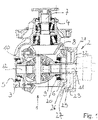
- differential gear 1 which is provided with a braking device 2 .
- the differential gear 1 has a differential housing 3 with an input opening 4 and two output openings 5 and 6.
- a drive shaft 7 is rotatably mounted in the input opening 4.
- a bevel gear 8 this drives a differential carrier 9, which is rotatably mounted in the differential housing 3 transversely to the axis of the drive shaft 7.
- the differential carrier 9 there is a bevel gear arrangement 10, with the aid of which a first output shaft 11 and a second output shaft 12 are driven, which protrude laterally from the output openings 5 and 6.
- the output shafts are connected to the front and rear wheels of a vehicle, respectively, while the input shaft 7 is coupled to the engine of the vehicle.
- both output shafts 11, 12 are loaded in the same way, the bevel gear arrangement 10 is virtually locked.
- the speed of the output shafts 11, 12 corresponds to the speed of the differential carrier 9. If a drive shaft can rotate more slowly than the other, because z. B. when cornering which drives a drive shaft the inner wheel, so there is a speed compensation via the bevel gear assembly 10.
- the braking device 2 acts on the differential carrier 9 and therefore causes both output shafts to be braked when it is actuated.
- the differential carrier 9 has an extension sleeve 20 which leads out of one of the outlet openings 6 and is connected to a passive element of the braking device 2 in a rotationally fixed manner.
- the passive element is a pot-shaped brake drum 21, which consists of a disc-shaped base 22 and a wall 23 running around it, the inside of which forms a cylindrical friction surface that serves as a braking surface for two brake shoes 25.
- the extension sleeve 20 is non-rotatably connected to the center of the base 22 .
- the brake shoes 25 are pivotally mounted on a support plate 26 which is disposed around and coaxially with the opening 6 and is fixed to the differential case 3 .
- the brake drum 21 has approximately the same outer diameter as the carrier plate 26, so that both enclose a chamber in which the brake shoes 25 are protected from external influences.
- the brake drum is designed as a radial brake disk 30, which is connected to the differential carrier 9 and whose wide lateral surface serves as a cylindrical friction surface.
- the brake shoes 25 are located on a cup-shaped carrier plate 31 and are pressed inwards against the friction surface for braking.
- a cover 32 closes the support plate 31 to the outside. It is also possible with this arrangement to connect the radial brake disk 30 directly to the drive shaft 7 .
- both output shafts 11, 12 should be provided with a braking device 2.
- a braking device 2 which acts on the differential carrier 9, while on the other side of the Differential housing, a braking device 2 is provided, which is connected to the local output shaft.
- braking device 2 which acts on the drive shaft 7 .
- the braking device is fastened to the inlet opening 4 instead of to one of the outlet openings 5, 6, as shown in FIGS.
- a third embodiment of the invention in which the braking devices 2 are arranged on a cylindrical housing 40 for an electric motor 41 and a differential carrier 9 .
- the rotor 42 and stator 43 are only indicated symbolically here to show that any form of electric motor is possible.
- the output shaft 44 of the electric motor 41 is hollow and widens into a flat pot 45 in which the differential carrier 9 is enclosed, so that it forms a non-rotatable connection with the output shaft 44 .
- the differential housing 3 consists of an annular carrier 46, which has an inwardly pointing flange 47, to which two half-shells 48 made of sheet metal are fastened, with output gears 49 being mounted in the cavity thus formed, the output gears 49 being rotatably fixed at their centers to the output shafts 11, 12 record, tape.
- Both output gears 49 engage in a compensating gear 50 which is rotatably mounted deaxially to the output shafts 11, 12 between the two half-shells 48.
- One of the output shafts 11 is guided through the hollow output shaft 44 of the electric motor 41 and is rotatably mounted there. Further bearings are located in the end faces of the housing 40.
- Brake shoes 25 are mounted on the end faces of housing 40, which is not detailed here, and can be pressed against a peripheral wall 23 of brake drum 21 by expanding means (not shown) in order to exert a braking torque on output shafts 11, 12. This corresponds to the execution 1 . It is conceivable, however, an embodiment of the braking device, as in the 2 is shown.
Landscapes
- Engineering & Computer Science (AREA)
- General Engineering & Computer Science (AREA)
- Mechanical Engineering (AREA)
- Transportation (AREA)
- Retarders (AREA)
- Braking Arrangements (AREA)
Description
- Die Erfindung bezieht sich auf ein eine Bremseinrichtung aufweisendes Differentialgetriebe mit einer Antriebswelle, zwei Abtriebswellen, ein Differentialgehäuse, das eine Eingangsöffnung für die Antriebswelle und zwei gegenüberliegende Ausgangsöffnungen für die Abtriebswellen aufweist, einem Differentialkorb und mit wenigstens einer Bremseinrichtung.
- Die gattungsfremde
US 3 621 957 A bezieht sich auf eine ausschließlich per Zündschloss deaktivierbare Sicherungseinrichtung gegen unbefugte Benutzung nach § 38 StVZO zwecks Absicherung gegen unautorisierte Fahrzeugnutzung, umfassend ein Achsdifferentialgetriebe mit einer Antriebswelle und mit zwei Achs-Abtriebswellen. Die Sicherung umfasst eine (dreh-)blockierte Trommel, die an einem Differentialkorb im Getriebegehäuseinneren fixiert ist. Die Sicherung ist stromlos aktiv mit einer off-Schaltfunktion, ohne dass eine reguläre Betriebsbremsfunktion offenbart noch beabsichtigt ist. Dabei ist die Sicherung grundsätzlich stromlos blockiert realisiert, indem die Trommel von einer Ringschelle als Blockierorgan von radial außen umschlungen ist, und wobei das Blockierorgan grundsätzlich über einen Federbolzen als Federspeicher in Blockierrichtung gegen die Trommel federvorgespannt ist. Zur Deaktivierung der Sicherung dient ein zündschlossbetätigter Aktuator in Gestalt eines Elektromagnetes mit angelenktem Exzenter, welcher dazu dient, das Blockierorgan mit eingeschalteter Zündung, entgegen der Speicherwirkung zu öffnen. - Die ähnlich gattungsfremde
JP S62 110034 A - Ein Achsdifferentialgetriebe mit gehäuseintegrierter Bremseinrichtung inclusive Bremsorgane für Kraftfahrzeuge ist in der
DE 38 13 528 A1 beschrieben. Demnach umfasst dies Differentialgetriebe zwei Lamellenbremseinrichtungen enthaltend drei verschieden arrangierte Lamellentypen. Darunter befindet sich eine Vielzahl von Lamellen, die radial von einer Abtriebswelle abstehen und zwischen Gegenlamellen ragen, welche unter anderem drehfest am Differentialgehäuse angeschlagen sind. Jedes so gebildete Lamellenpaket wird hydraulisch in axialer Richtung zusammengedrückt, um Bremswirkung zu erzeugen. - Die
DE 39 35 115 A1 betrifft eine angetriebene Lenkachsbaugruppe mit hydraulisch betätigbarer Differentialsperre einschließlich Bremse, umfassend ein Differentialsperrenlamellenpaket sowie zwei Bremslamellenpakete in Verbindung mit Steckwellen, inclusive des Bonuseffektes einer Antiblockieroption, unabhängig vom Lenkeinschlag oder der Bremse, für unterschiedliche Bodenhaftung der Räder. Dabei ist eine individuell dosierbare Bremsbetätigung ohne Belastungsänderung der fremdbetätigbar gestalteten Differentialsperre angestrebt. Zudem wird empfohlen die Bremse, durch Einbau in einer als Zwischenflansch ausgebildeten Gehäusezwischenwand, fakultativ nachrüstbar vorzusehen. - Die
DE 10 2005 018 907 A1 beschreibt ein Ausgleichsgetriebe für eine elektrisch angetriebene Antriebsachse einschließlich Multilamellenbremsanordnung in Ausgestaltung als kombinierte Fahrzeugbremse, wobei mindestens eine drehbare Lamelle mit einem Differentialkorb derart in Verbindung steht, dass bei Bremsbetätigung ein Achswellenrad sowie der Differentialkorb zum Ausgleichgetriebegehäuse so gebremst sind, dass beide Abtriebswellen gebremst sind. Dabei erfolgt die Ansteuerung für die Betriebsbremsfunktion über hydraulische Kolben und die Ansteuerung für die Feststellbremsfunktion erfolgt gesondert mechanisch über eine Welle. - Bekannte Differentialgetriebe mit Multilamellenbremse haben den Nachteil, dass Bremsorgane aufwändig zu warten sind, da diese innerhalb des Differentialgehäuses des Differentialgetriebes angeordnet sind.
- Die Erfindung beruht auf der Aufgabe, technische Nachteile laut Stand der Technik zu vermeiden, und zudem die Bremseinrichtung an einem Differentialgetriebe baulich zu vereinfachen.
- Zur Lösung der Aufgabe sieht die Erfindung vor, dass die wenigstens eine Bremseinrichtung eine Trommelbremse ist, die ein passives Element, das eine zylindrische Reibfläche besitzt, und Bremsbacken aufweist, deren Reibflächen an die zylindrische Reibfläche des passiven Elementes anlegbar sind, dass das passive Element an dem Differentialkorb und /oder an einer der Wellen derart befestigt ist, dass seine zylindrische Reibfläche koaxial zu einer der Öffnungen angeordnet ist, und dass die Bremsbacken auf einer Trägerplatte schwenkbar gehalten sind, die an den Rand der genannten Öffnung angeflanscht ist.
- Weil mit dieser Konstruktion die Bremseinrichtung als gesondertes Bauteil außerhalb des Differentialgehäuses, aber im unmittelbaren Anschluss daran angeordnet ist, ist die Bremseinrichtung insbesondere für Wartungszwecke leicht zugänglich.
- Vorzugsweise wird das passive Element, das ist das Element der Bremseinrichtung, das nicht verstellbar ist, von einem Topf gebildet, der aus einem Boden und einer umlaufenden Wand besteht, wobei die Innenseite der Wand die zylindrische Reibfläche bildet. Die offene Seite des Topfes weist zum Differentialgehäuse des Differentialgetriebes, wobei innerhalb des Topfes die Bremsbacken angeordnet sind. Auf diese Weise liegen die Bremsbacken, die gegen das passive Element verstellbar sind, gekapselt und geschützt in einer Kammer, die von der Trägerplatte und der Bremstrommel gebildet wird.
- Alternativ kann das passive Element von einer Radialbremsscheibe gebildet sein, deren Mantelfläche die zylindrische Reibfläche bildet.
- Um auch hier eine gekapselte Anordnung der Bremsbacken zu erreichen, ist auf der Trägerplatte ein Deckel lösbar befestigt, so dass die Trägerplatte mit den Bremsbacken und die Radialbremsscheibe eingehaust sind.
- Vorzugsweise ist an beiden Abtriebswellen jeweils eine Bremseinrichtung installiert.
- Eine bessere Bremswirkung wird erzielt, wenn das passive Element der einen Bremseinrichtung mit dem Differentialkorb und das passive Element der anderen Bremseinrichtung mit einer der Abtriebswellen gekoppelt ist.
- Damit das passive Element an dem Differentialkorb befestigt werden kann, ist dieser an einer Seite koaxial zur dortigen Abtriebswelle mittels einer Verlängerungshülse verlängert.
- In einigen Fällen wird es ausreichen, dass eine einzige Bremseinrichtung an der Antriebswelle angeordnet ist. Deren Bremswirkung setzt sich über den Differentialkorb auf die Abtriebswellen fort.
- Um die Bremseinrichtung betätigen zu können, ist vorgesehen, dass die Trägerplatte nach außen radial über das Differentialgehäuse vorsteht, und an seiner Rückseite einen hydraulischen oder elektrischen Anschluss für die Stelleinrichtung der Bremsbacken aufweist.
- Die Erfindung lässt sich auch besonders gut bei Differentialgetrieben einsetzen, die unmittelbar mit einem Elektromotor gekoppelt sind. Hier sind sehr kompakt bauende Anordnungen bekannt, bei denen das Getriebe selbst relativ flach ausgeführt ist und an der Stirnseite eines Elektromotors angeordnet wird.
- Dabei ist ein zweiter, schwächerer Elektromotor vorgesehen, der ebenfalls zu einem Drehmomentausgleich beiträgt.
- Die Erfindung sieht daher vor, diesen zweiten Elektromotor mit entsprechenden Bremseinrichtungen, wie sie zuvor beschrieben sind, zu ersetzen.
- Dazu ist vorgesehen, dass der Differentialkorb mit der Abtriebswelle eines Elektromotors gekoppelt ist, wobei die Abtriebswelle hohl ausgeführt ist, und koaxial zu einer der Abtriebswellen des Differentialgetriebes verläuft.
- Um die kompakte Form des Differentialgetriebes zu erhalten, ist vorgesehen, dass ein Ausgleichszahnrad in Form eines Stirnzahnrades deaxial zu den Abtriebswellen im Differentialkorb gelagert ist und dass die Abtriebswellen mit je einem Abtriebszahnrad, das ebenfalls als Stirnzahnrad ausgebildet ist, in die Verzahnung des Ausgleichszahnrades eingreifen.
- Vorzugsweise werden der Elektromotor und der Differentialkorb in einem gemeinsamen zylindrischen Gehäuse untergebracht, wobei die Abtriebswellen durch die Stirnseiten des Gehäuses hindurchgeführt sind. Die Bremseinrichtungen können dann an einer oder beiden Stirnseiten angeordnet werden.
- Im Folgenden soll anhand von drei Ausführungsbeispielen die Erfindung näher erläutert werden. Dazu zeigen:
- Fig. 1
- eine erste Ausführungsform der Erfindung,
- Fig. 2
- eine zweite Ausführungsform der Erfindung, und
- Fig. 3
- eine dritte Ausführungsform der Erfindung.
- Zunächst wird zur Beschreibung des Differentialgetriebes auf die ersten beiden Figuren Bezug genommen. Diese zeigen jeweils im Schnitt ein Differentialgetriebe 1, das mit einer Bremseinrichtung 2 versehen ist.
- Das Differentialgetriebe 1 weist ein Differentialgehäuse 3 auf mit einer Eingangsöffnung 4 und zwei Ausgangsöffnungen 5 und 6. In der Eingangsöffnung 4 ist eine Antriebswelle 7 drehbar gelagert. Diese treibt über ein Kegelzahnrad 8 einen Differentialkorb 9 an, der quer zur Achse der Antriebswelle 7 im Differentialgehäuse 3 drehbar gelagert ist.
- In dem Differentialkorb 9 befindet sich eine Kegelzahnradanordnung 10, mit deren Hilfe eine erste Abtriebswelle 11 und eine zweite Abtriebswelle 12 angetrieben werden, die seitlich aus den Ausgangsöffnungen 5 und 6 hervorstehen. Die Abtriebswellen werden mit den Vorder- bzw. Hinterrädern eines Fahrzeuges verbunden, währen die Antriebswelle 7 mit dem Motor des Fahrzeuges gekoppelt wird.
- Falls beide Abtriebswellen 11, 12 gleicher Weise belastet sind, ist die Kegelzahnradanordnung 10 quasi gesperrt. Die Drehzahl der Abtriebswellen 11, 12 entspricht der Drehzahl des Differentialkorbes 9. Wenn sich die eine Antriebswelle nur langsamer drehen kann als die andere, weil z. B. bei einer Kurvenfahrt die eine Antriebswelle das innere Rad antreibt, so erfolgt ein Drehzahlausgleich über die Kegelzahnradanordnung 10.
- Die Bremseinrichtung 2 wirkt auf den Differentialkorb 9 und bewirkt daher bei ihrer Betätigung die Abbremsung beider Abtriebswellen. Dazu besitzt der Differentialkorb 9 eine Verlängerungshülse 20, die aus einer der Ausgangsöffnungen 6 herausführt, und mit einem passiven Element der Bremseinrichtung 2 drehfest verbunden ist.
- Gemäß der Ausführung nach
Fig. 1 wird die Bremseinrichtung von einer Trommelbremse realisiert, wie sie in der Fahrzeugtechnik üblich ist. Demnach ist das passive Element eine topfförmige Bremstrommel 21, die aus einem scheibenförmigen Boden 22 und einer daran umlaufenden Wand besteht 23, deren Innenseite eine zylindrische Reibfläche bildet, die als Bremsfläche für zwei Bremsbacken 25 dient. Die Verlängerungshülse 20 ist mit dem Zentrum des Bodens 22 drehfest verbunden. - Die Bremsbacken 25 sind auf einer Trägerplatte 26 schwenkbar angeordnet, die um die Öffnung 6 herum und koaxial dazu angeordnet ist und an dem Differentialgehäuse 3 befestigt ist.
- Auf der Trägerplatte 26 befinden sich - was hier nicht näher dargestellt ist - Betätigungseinrichtungen, z. B. hydraulische oder elektromotorische Betätigungseinrichtungen für die Bremsbacken 25. Diese werden über einen Anschluss 27 versorgt, der sich an der Rückseite der Trägerplatte 26 befindet und zwar in einem Bereich, der radial über das Differentialgehäuse 3 hinausragt. Die Bremstrommel 21 hat in etwa den gleichen Außendurchmesser wie die Trägerplatte 26, so dass beide eine Kammer einschließen, in der sich die Bremsbacken 25 geschützt vor Außeneinwirkungen befinden.
- Eine alternative Form der Bremseinrichtung 2 ist in der
Fig. 2 dargestellt. Hier ist die Bremstrommel als Radialbremsscheibe 30 ausgeführt, die mit dem Differentialkorb 9 verbunden ist und deren breite Mantelfläche als zylindrische Reibfläche dient. Die Bremsbacken 25 befinden sich auf einer topfförmigen Trägerplatte 31 und werden zu Bremsbetätigung nach innen gegen die Reibfläche gedrückt. Ein Deckel 32 verschließt die Trägerplatte 31 nach außen. Auch bei dieser Anordnung ist es möglich, die Radialbremsscheibe 30 unmittelbar mit der Antriebswelle 7 zu verbinden. - Für beide Ausführungen gilt grundsätzlich, dass die Bremstrommel 21 bzw. Radialbremsscheibe 30 nicht nur am Differentialkorb 9, sondern statt dessen direkt mit der jeweiligen Abtriebswelle 11, 12 gekoppelt ist. In diesem Fall sollten beide Abtriebswellen 11, 12 mit einer Bremseinrichtung 2 versehen sein. Denkbar wäre aber auch, dass eine Bremseinrichtung 2 vorgesehen ist, die auf den Differentialkorb 9 wirkt, während auf der anderen Seite des Differentialgehäuses eine Bremseinrichtung 2 vorgesehen ist, die mit der dortigen Abtriebwelle verbunden ist.
- Des Weiteren kann nur eine Bremseinrichtung 2 vorgesehen werden, die auf die Antriebswelle 7 wirkt. Die Bremseinrichtung wird entsprechend den Darstellungen in der Fig.l und 2 statt an einer der Ausgangsöffnung 5, 6 an der Eingangsöffnung 4 befestigt.
- In der
Fig. 3 ist eine dritte Ausführungsform der Erfindung beschrieben, bei der die Bremseinrichtungen 2 an einem zylindrischen Gehäuse 40 für einen Elektromotor 41 und einem Differentialkorb 9 angeordnet sind. - Der Rotor 42 und Stator 43 sind hier nur symbolisch angedeutet, um zu zeigen, dass jedwede Form von Elektromotoren möglich ist.
- Die Abtriebswelle 44 des Elektromotors 41 ist hohl ausgeführt und erweitert sich zu einem flachen Topf 45, in dem der Differentialkorb 9 eingefasst ist, so dass er eine drehfeste Verbindung mit der Abtriebswelle 44 eingeht.
- Das Differentialgehäuse 3 besteht aus einem ringförmigen Träger 46, der einen nach innen weisenden Flansch 47 aufweist, an dem zwei Halbschalen 48 aus Blech befestigt sind, wobei in dem so gebildeten Hohlraum Abtriebszahnräder 49 gelagert sind, die in ihren Zentren die Abtriebswellen 11, 12 drehfest aufnehmen.
- Beide Abtriebszahnräder 49 greifen in ein Ausgleichszahnrad 50 ein, das deaxial zu den Abtriebswellen 11, 12 zwischen den beiden Halbschalen 48 drehbar gelagert ist.
- Die eine der Abtriebswellen 11 ist durch die hohle Abtriebswelle 44 des Elektromotors 41 geführt und dort drehbar gelagert. Weitere Lager befinden sich in den Stirnseiten des Gehäuses 40.
- Wie schon weiter oben beschrieben, sind an den Abtriebswellen 11, 12 außerhalb des Gehäuses 40 Bremstrommeln 21 drehfest angebracht. An den Stirnseiten des Gehäuses 40 sind, was hier nicht näher ausgeführt ist, Bremsbacken 25 gelagert, die durch nicht dargestellte Spreizmittel gegen eine umlaufende Wand 23 der Bremstrommel 21 gedrückt werden können, um ein bremsendes Moment auf die Abtriebswellen 11, 12 auszuüben. Dies entspricht der Ausführung nach
Fig. 1 . Denkbar ist allerdings eine Ausführung der Bremseinrichtung, wie sie in derFig. 2 dargestellt ist.Bezugszeichenliste 1 Differentialgetriebe 26 Trägerplatte 2 Bremseinrichtung 27 Anschluss 3 Differentialgehäuse 4 Eingangsöffnung 30 Radialbremsscheibe 5 Ausgangsöffnung 31 Trägerplatte 32 Deckel 6 Ausgangsöffnung 7 Antriebswelle 40 zylindrisches Gehäuse 8 Kegelzahnrad 41 Elektromotor 9 Differentialkorb 42 Rotor 10 Kegelzahnradanordnung 43 Stator 44 Abtriebswelle 11 Abtriebswelle 12 Abtriebswelle 45 46 Topf Träger 20 Verlängerungshülse 47 Flansch 21 Bremstrommel 48 Halbschalen 22 Boden 49 Abtriebszahnräder 23 umlaufende Wand 50 Ausgleichszahnrad 25 Bremsbacken
Claims (12)
- Differentialgetriebe (1) mit Bremseinrichtung (2), umfassend eine Antriebswelle (7), zwei Abtriebswellen (11, 12), ein Differentialgehäuse (3), das eine Eingangsöffnung (4) für die Antriebswelle (7) und zwei gegenüberliegende Ausgangsöffnungen (5, 6) für die Abtriebswellen (11, 12) aufweist, sowie mit einem Differentialkorb (9), wobei die wenigstens eine Bremseinrichtung (2) eine Trommelbremse ist, die ein passives Element (21, 30), das eine zylindrischen Reibfläche besitzt, und Bremsbacken (25) aufweist, deren Reibflächen an die zylindrische Reibfläche des passiven Elements (21, 30) anlegbar sind, dass das passive Element (21, 30) an dem Differentialkorb (9) und/oder an einer der Wellen (7, 11, 12) derart befestigt ist, dass seine zylindrische Reibfläche koaxial zu der jeweiligen Öffnung (4, 5, 6) angeordnet ist, und dass die Bremsbacken (25) auf einer Trägerplatte (26, 31) schwenkbar gehalten sind, die an einen Rand der genannten Öffnung (4, 5, 6) angeflanscht ist.
- Differentialgetriebe (1) nach Anspruch 1, dadurch gekennzeichnet, dass das passive Element (21, 30) von einem Topf (45) gebildet ist, der aus einem Boden (22) und einer umlaufenden Wand (23) besteht, wobei die Innenseite der Wand (23) die zylindrische Reibfläche bildet, dass die offene Seite des Topfes (45) zum Differentialgehäuse (3) des Differentialgetriebes (1) weist, und dass innerhalb des Topfes (45) die Bremsbacken (25) angeordnet sind.
- Differentialgetriebe (1) nach Anspruch 1, dadurch gekennzeichnet, dass das passive Element (21, 30) von einer Radialbremsscheibe (30) gebildet ist, deren Mantelfläche die zylindrische Reibfläche bildet.
- Differentialgetriebe (1) nach Anspruch 3, dadurch gekennzeichnet, dass auf der Trägerplatte (31) ein Deckel (32) lösbar befestigt ist, so dass die Trägerplatte (31), die Bremsbacken (25) und die Radialbremsscheibe (30) eingehaust sind.
- Differentialgetriebe (1) nach einem der vorhergehenden Ansprüche, dadurch gekennzeichnet, dass koaxial zu beiden Abtriebswellen (11, 12) jeweils eine Bremseinrichtung (2) installiert ist.
- Differentialgetriebe (1) nach Anspruch 5, dadurch gekennzeichnet, dass das passive Element (21, 30) der einen Bremseinrichtung (2) mit dem Differentialkorb (9) und das passive Element (21, 30) der anderen Bremseinrichtung (2) mit einer der Abtriebswellen (11, 12) gekoppelt ist.
- Differentialgetriebe (1) nach Anspruch 6, dadurch gekennzeichnet, dass der Differentialkorb (9) an einer Seite koaxial zur dortigen Abtriebswelle (11, 12) mittels einer Verlängerungshülse (20) verlängert ist, um eine Befestigung des passiven Elements (21, 30) zu ermöglichen.
- Differentialgetriebe (1) nach einem der Ansprüche 1 bis 4, dadurch gekennzeichnet, dass eine einzige Bremseinrichtung (2) an der Antriebswelle (7) angeordnet ist.
- Differentialgetriebe (1) nach einem der vorhergehenden Ansprüche 1 bis 4, dadurch gekennzeichnet, dass die Trägerplatte (26, 31) nach außen radial über das Differentialgehäuse (3) vorsteht, und an seiner Rückseite einen hydraulischen oder elektrischen Anschluss (27) für eine Stelleinrichtung der Bremsbacken (25) aufweist.
- Differentialgetriebe (1) nach einem der vorhergehenden Ansprüche, dadurch gekennzeichnet, dass der Differentialkorb (9) mit einer Abtriebswelle (44) eines Elektromotors (41) gekoppelt ist, wobei die Abtriebswelle (44) hohl ausgeführt ist und koaxial zu einer der Abtriebswellen (11, 12) des Differentialgetriebes (1) verläuft.
- Differentialgetriebe (1) nach Anspruch 10, dadurch gekennzeichnet, dass ein Ausgleichszahnrad (50) in Form eines Stirnzahnrades deaxial zu den Abtriebswellen (11,12) im Differentialkorb (9) gelagert ist, und dass die Abtriebswellen (11,12) mit je einem Abtriebszahnrad (49), das als Stirnzahnrad ausgebildet ist, in die Verzahnung des Ausgleichszahnrades (50) eingreifen.
- Differentialgetriebe (1) nach einem der vorhergehenden Ansprüche, dadurch gekennzeichnet, dass der Elektromotor (41) und der Differentialkorb (9) in einem gemeinsamen zylindrischen Gehäuse (40) untergebracht sind, wobei die Abtriebswellen (11,12) durch Stirnseiten des Gehäuses (40) hindurchgeführt sind und dass an einer oder an beiden Stirnseite(n) je eine Bremseinrichtung (2) angeordnet ist.
Applications Claiming Priority (2)
| Application Number | Priority Date | Filing Date | Title |
|---|---|---|---|
| DE102016214968.7A DE102016214968A1 (de) | 2016-08-11 | 2016-08-11 | Eine Bremseinrichtung aufweisendes Differentialgetriebe |
| PCT/EP2017/070109 WO2018029211A1 (de) | 2016-08-11 | 2017-08-08 | Eine bremseinrichtung aufweisendes differentialgetriebe |
Publications (2)
| Publication Number | Publication Date |
|---|---|
| EP3496987A1 EP3496987A1 (de) | 2019-06-19 |
| EP3496987B1 true EP3496987B1 (de) | 2022-11-02 |
Family
ID=59564205
Family Applications (1)
| Application Number | Title | Priority Date | Filing Date |
|---|---|---|---|
| EP17749474.7A Active EP3496987B1 (de) | 2016-08-11 | 2017-08-08 | Eine bremseinrichtung aufweisendes differentialgetriebe |
Country Status (8)
| Country | Link |
|---|---|
| US (1) | US10889270B2 (de) |
| EP (1) | EP3496987B1 (de) |
| JP (1) | JP6968153B2 (de) |
| KR (2) | KR20210145316A (de) |
| CN (1) | CN109476328B (de) |
| BR (1) | BR112018076705A2 (de) |
| DE (1) | DE102016214968A1 (de) |
| WO (1) | WO2018029211A1 (de) |
Families Citing this family (5)
| Publication number | Priority date | Publication date | Assignee | Title |
|---|---|---|---|---|
| CN112360906A (zh) * | 2020-11-04 | 2021-02-12 | 安徽开乐专用车辆股份有限公司 | 一种鼓式制动器的散热方法 |
| DE102020214433B4 (de) | 2020-11-17 | 2026-03-19 | Aumovio Germany Gmbh | Antriebseinheit mit einem Elektromotor |
| WO2024022562A1 (de) | 2022-07-25 | 2024-02-01 | Continental Automotive Technologies GmbH | Achsschenkelintegriertes kraftmodul |
| DE102023200461A1 (de) | 2022-07-25 | 2024-01-25 | Continental Automotive Technologies GmbH | Achsschenkelintegriertes Kraftmodul |
| DE102023123187B4 (de) | 2023-08-29 | 2025-03-13 | Schaeffler Technologies AG & Co. KG | Bremsvorrichtung für ein Fahrzeug, Antriebsanordnung mit der Bremsvorrichtung sowie Fahrzeug |
Family Cites Families (29)
| Publication number | Priority date | Publication date | Assignee | Title |
|---|---|---|---|---|
| US1448670A (en) * | 1922-04-14 | 1923-03-13 | Ira M Marcy | Differential gear |
| CH276589A (de) * | 1952-02-04 | 1951-07-15 | Schmidt Helmut | Bremseinrichtung an Kraftfahrzeugen. |
| DE1070049B (de) * | 1955-04-06 | |||
| DE1655348A1 (de) * | 1967-01-25 | 1971-10-21 | Teves Gmbh Alfred | Bremsensystem fuer Kraftfahrzeuge |
| US3621957A (en) | 1969-10-31 | 1971-11-23 | Laurence L Howe | Automatic safety brake for automotive vehicles |
| JPS48108085U (de) * | 1972-03-18 | 1973-12-13 | ||
| JPS62110034A (ja) * | 1985-11-06 | 1987-05-21 | Honda Motor Co Ltd | 動力伝達、遮断装置 |
| DE3876247D1 (de) | 1987-04-25 | 1993-01-07 | Zahnradfabrik Friedrichshafen | Bremsanlage. |
| JPH0182338U (de) * | 1987-11-20 | 1989-06-01 | ||
| JPH07759Y2 (ja) * | 1988-05-30 | 1995-01-11 | 株式会社神崎高級工機製作所 | 自走式作業車のトランスミツシヨン |
| DE3935115A1 (de) | 1988-11-11 | 1990-05-17 | Zahnradfabrik Friedrichshafen | Achsbaugruppe mit gemeinsam betaetigbarer differentialsperre und bremse |
| DE29613282U1 (de) | 1996-07-31 | 1997-03-20 | Clark Material Handling GmbH, 45478 Mülheim | Fahrzeug mit elektrischem Antriebsmotor, insbesondere als Flurförderzeug |
| GB2344089B (en) * | 1998-11-30 | 2000-10-04 | Daimler Chrysler Ag | Apparatus for transmitting torques for motor vehicles |
| JP2000247215A (ja) * | 1999-02-25 | 2000-09-12 | Suzuki Motor Corp | 小型電動車両のブレーキ構造 |
| DE10026558C2 (de) * | 1999-11-25 | 2002-05-29 | Daimler Chrysler Ag | Vorrichtung zur Übertragung von Bremsmomenten für Kraftfahrzeuge |
| JP4636651B2 (ja) | 2000-04-07 | 2011-02-23 | Gknドライブラインジャパン株式会社 | 動力伝達装置 |
| DE10203294A1 (de) * | 2002-01-29 | 2003-08-14 | Gkn Viscodrive Gmbh | Differentialanrordnung |
| US7731614B2 (en) * | 2002-04-29 | 2010-06-08 | Caterpillar Inc. | Method and apparatus for an electric drive differential system |
| FR2847627B1 (fr) | 2002-11-22 | 2006-02-10 | Bosch Gmbh Robert | Frein a tambour et segment pour un tel frein |
| DE10327458A1 (de) * | 2003-06-18 | 2005-01-05 | Audi Ag | Bremsanlage für Kraftfahrzeuge |
| JP2006198377A (ja) * | 2005-01-21 | 2006-08-03 | Araya Industrial Co Ltd | 車椅子用バンドブレーキ |
| DE102005018907A1 (de) | 2005-04-22 | 2006-11-09 | Zf Friedrichshafen Ag | Ausgleichsgetriebe für eine elektrisch angetriebene Antriebsachse |
| US7686141B2 (en) | 2005-06-29 | 2010-03-30 | Harmonic Ad, Inc. | Brake-equipped retracting device for retractable member |
| CN100484795C (zh) | 2007-05-14 | 2009-05-06 | 无锡开普动力有限公司 | 一种装载机的行走制动装置 |
| DE102009018828A1 (de) * | 2009-04-24 | 2010-11-04 | Tekfor Cologne Gmbh | Parksperre |
| CN201461893U (zh) | 2009-05-31 | 2010-05-12 | 施焕潮 | 具有辅助制动作用的差速器 |
| DE102011008846B4 (de) | 2010-01-18 | 2023-07-06 | Vitesco Technologies GmbH | Ansteuerverfahren für eine elektrisch betriebene Bremse eines Bremssystems für ein Sperr-Differentialgetriebe |
| DE102011018861A1 (de) | 2011-04-28 | 2012-10-31 | Magna Powertrain Ag & Co. Kg | Antriebseinheit für ein Hybridfahrzeug |
| JP2012241821A (ja) * | 2011-05-20 | 2012-12-10 | Ntn Corp | 電気自動車用減速差動装置 |
-
2016
- 2016-08-11 DE DE102016214968.7A patent/DE102016214968A1/de not_active Withdrawn
-
2017
- 2017-08-08 KR KR1020217037913A patent/KR20210145316A/ko not_active Ceased
- 2017-08-08 KR KR1020197004789A patent/KR20190032446A/ko not_active Ceased
- 2017-08-08 WO PCT/EP2017/070109 patent/WO2018029211A1/de not_active Ceased
- 2017-08-08 US US16/317,868 patent/US10889270B2/en not_active Expired - Fee Related
- 2017-08-08 EP EP17749474.7A patent/EP3496987B1/de active Active
- 2017-08-08 JP JP2019507222A patent/JP6968153B2/ja not_active Expired - Fee Related
- 2017-08-08 BR BR112018076705-0A patent/BR112018076705A2/pt not_active Application Discontinuation
- 2017-08-08 CN CN201780041983.5A patent/CN109476328B/zh active Active
Also Published As
| Publication number | Publication date |
|---|---|
| CN109476328A (zh) | 2019-03-15 |
| US10889270B2 (en) | 2021-01-12 |
| CN109476328B (zh) | 2021-07-30 |
| WO2018029211A1 (de) | 2018-02-15 |
| DE102016214968A1 (de) | 2018-02-15 |
| JP2019528209A (ja) | 2019-10-10 |
| US20190232927A1 (en) | 2019-08-01 |
| KR20210145316A (ko) | 2021-12-01 |
| EP3496987A1 (de) | 2019-06-19 |
| KR20190032446A (ko) | 2019-03-27 |
| JP6968153B2 (ja) | 2021-11-17 |
| BR112018076705A2 (pt) | 2019-04-02 |
Similar Documents
| Publication | Publication Date | Title |
|---|---|---|
| EP3496987B1 (de) | Eine bremseinrichtung aufweisendes differentialgetriebe | |
| DE3801716C2 (de) | Differentialgetriebe | |
| DE688425C (de) | Lamellenbremse | |
| EP2703675B2 (de) | Doppelkupplung mit stehendem Kolben und verbesserten Einrücklagern | |
| DE3211366C2 (de) | Federspeicherbremse mit druckmittelbetätigbarer Lüfteinrichtung | |
| DE2533611A1 (de) | Radantriebsvorrichtung | |
| DE2104929B2 (de) | Radlagerung für ein mit einer Scheibenbremse versehenes Rad eines motorgetriebenen Stra Benfahrzeugs | |
| DE3617074C2 (de) | ||
| DE19913024C2 (de) | Radlagerung für Fahrzeugachsen | |
| EP2962865A1 (de) | Nabenanordnung, insbesondere für zwillingsräder | |
| DE60211202T2 (de) | Anordnung zum antrieb eines fahrzeugrads | |
| DE102007053325B4 (de) | Antriebsstrangbremse für Nutzfahrzeug | |
| DE3339688A1 (de) | Radnabe mit integrierter bremse | |
| DE3339687A1 (de) | Radnabe mit integriertem untersetzungsgetriebe | |
| DE102019118659A1 (de) | Bremsanordnung für einen Radnabenantrieb sowie Radnabenantrieb mit der Bremsanordnung | |
| DE60101498T2 (de) | Radaufhängung an Achsbrücke oder Achse für Motorfahrzeuge | |
| DE19624288C1 (de) | Achse mit Bremse für einen Radbagger | |
| DE102015118052A1 (de) | Nabenanordnung für Zwillingsräder | |
| DE102008011338B4 (de) | Automatisches Schaltgetriebe mit abbremsbarer Planeteneinheit | |
| DE102021215118B4 (de) | Bremsanordnung und Verfahren zum Betreiben einer Bremsanordnung für ein Fahrzeugrad | |
| DE102007059531A1 (de) | Selbstsperrendes Kronenraddifferential und seine Verwendung | |
| DE10259156B4 (de) | Radnabe für die Lagerung eines Fahrzeugsrades | |
| DE19858033A1 (de) | Differentialgetriebe für Kraftfahrzeuge | |
| DE1025279B (de) | Ausgleichgetriebe fuer Kraftfahrzeuge | |
| DE19903564A1 (de) | Bremse |
Legal Events
| Date | Code | Title | Description |
|---|---|---|---|
| STAA | Information on the status of an ep patent application or granted ep patent |
Free format text: STATUS: UNKNOWN |
|
| STAA | Information on the status of an ep patent application or granted ep patent |
Free format text: STATUS: THE INTERNATIONAL PUBLICATION HAS BEEN MADE |
|
| PUAI | Public reference made under article 153(3) epc to a published international application that has entered the european phase |
Free format text: ORIGINAL CODE: 0009012 |
|
| STAA | Information on the status of an ep patent application or granted ep patent |
Free format text: STATUS: REQUEST FOR EXAMINATION WAS MADE |
|
| 17P | Request for examination filed |
Effective date: 20190311 |
|
| AK | Designated contracting states |
Kind code of ref document: A1 Designated state(s): AL AT BE BG CH CY CZ DE DK EE ES FI FR GB GR HR HU IE IS IT LI LT LU LV MC MK MT NL NO PL PT RO RS SE SI SK SM TR |
|
| AX | Request for extension of the european patent |
Extension state: BA ME |
|
| DAV | Request for validation of the european patent (deleted) | ||
| DAX | Request for extension of the european patent (deleted) | ||
| GRAP | Despatch of communication of intention to grant a patent |
Free format text: ORIGINAL CODE: EPIDOSNIGR1 |
|
| STAA | Information on the status of an ep patent application or granted ep patent |
Free format text: STATUS: GRANT OF PATENT IS INTENDED |
|
| INTG | Intention to grant announced |
Effective date: 20220617 |
|
| RAP1 | Party data changed (applicant data changed or rights of an application transferred) |
Owner name: CONTINENTAL AUTOMOTIVE TECHNOLOGIES GMBH |
|
| GRAS | Grant fee paid |
Free format text: ORIGINAL CODE: EPIDOSNIGR3 |
|
| GRAA | (expected) grant |
Free format text: ORIGINAL CODE: 0009210 |
|
| STAA | Information on the status of an ep patent application or granted ep patent |
Free format text: STATUS: THE PATENT HAS BEEN GRANTED |
|
| AK | Designated contracting states |
Kind code of ref document: B1 Designated state(s): AL AT BE BG CH CY CZ DE DK EE ES FI FR GB GR HR HU IE IS IT LI LT LU LV MC MK MT NL NO PL PT RO RS SE SI SK SM TR |
|
| REG | Reference to a national code |
Ref country code: GB Ref legal event code: FG4D Free format text: NOT ENGLISH |
|
| REG | Reference to a national code |
Ref country code: CH Ref legal event code: EP Ref country code: AT Ref legal event code: REF Ref document number: 1528565 Country of ref document: AT Kind code of ref document: T Effective date: 20221115 |
|
| REG | Reference to a national code |
Ref country code: DE Ref legal event code: R096 Ref document number: 502017014045 Country of ref document: DE |
|
| REG | Reference to a national code |
Ref country code: IE Ref legal event code: FG4D Free format text: LANGUAGE OF EP DOCUMENT: GERMAN |
|
| REG | Reference to a national code |
Ref country code: LT Ref legal event code: MG9D |
|
| REG | Reference to a national code |
Ref country code: NL Ref legal event code: MP Effective date: 20221102 |
|
| PG25 | Lapsed in a contracting state [announced via postgrant information from national office to epo] |
Ref country code: SE Free format text: LAPSE BECAUSE OF FAILURE TO SUBMIT A TRANSLATION OF THE DESCRIPTION OR TO PAY THE FEE WITHIN THE PRESCRIBED TIME-LIMIT Effective date: 20221102 Ref country code: PT Free format text: LAPSE BECAUSE OF FAILURE TO SUBMIT A TRANSLATION OF THE DESCRIPTION OR TO PAY THE FEE WITHIN THE PRESCRIBED TIME-LIMIT Effective date: 20230302 Ref country code: NO Free format text: LAPSE BECAUSE OF FAILURE TO SUBMIT A TRANSLATION OF THE DESCRIPTION OR TO PAY THE FEE WITHIN THE PRESCRIBED TIME-LIMIT Effective date: 20230202 Ref country code: LT Free format text: LAPSE BECAUSE OF FAILURE TO SUBMIT A TRANSLATION OF THE DESCRIPTION OR TO PAY THE FEE WITHIN THE PRESCRIBED TIME-LIMIT Effective date: 20221102 Ref country code: FI Free format text: LAPSE BECAUSE OF FAILURE TO SUBMIT A TRANSLATION OF THE DESCRIPTION OR TO PAY THE FEE WITHIN THE PRESCRIBED TIME-LIMIT Effective date: 20221102 Ref country code: ES Free format text: LAPSE BECAUSE OF FAILURE TO SUBMIT A TRANSLATION OF THE DESCRIPTION OR TO PAY THE FEE WITHIN THE PRESCRIBED TIME-LIMIT Effective date: 20221102 |
|
| PG25 | Lapsed in a contracting state [announced via postgrant information from national office to epo] |
Ref country code: RS Free format text: LAPSE BECAUSE OF FAILURE TO SUBMIT A TRANSLATION OF THE DESCRIPTION OR TO PAY THE FEE WITHIN THE PRESCRIBED TIME-LIMIT Effective date: 20221102 Ref country code: PL Free format text: LAPSE BECAUSE OF FAILURE TO SUBMIT A TRANSLATION OF THE DESCRIPTION OR TO PAY THE FEE WITHIN THE PRESCRIBED TIME-LIMIT Effective date: 20221102 Ref country code: LV Free format text: LAPSE BECAUSE OF FAILURE TO SUBMIT A TRANSLATION OF THE DESCRIPTION OR TO PAY THE FEE WITHIN THE PRESCRIBED TIME-LIMIT Effective date: 20221102 Ref country code: IS Free format text: LAPSE BECAUSE OF FAILURE TO SUBMIT A TRANSLATION OF THE DESCRIPTION OR TO PAY THE FEE WITHIN THE PRESCRIBED TIME-LIMIT Effective date: 20230302 Ref country code: HR Free format text: LAPSE BECAUSE OF FAILURE TO SUBMIT A TRANSLATION OF THE DESCRIPTION OR TO PAY THE FEE WITHIN THE PRESCRIBED TIME-LIMIT Effective date: 20221102 Ref country code: GR Free format text: LAPSE BECAUSE OF FAILURE TO SUBMIT A TRANSLATION OF THE DESCRIPTION OR TO PAY THE FEE WITHIN THE PRESCRIBED TIME-LIMIT Effective date: 20230203 |
|
| P01 | Opt-out of the competence of the unified patent court (upc) registered |
Effective date: 20230522 |
|
| PG25 | Lapsed in a contracting state [announced via postgrant information from national office to epo] |
Ref country code: NL Free format text: LAPSE BECAUSE OF FAILURE TO SUBMIT A TRANSLATION OF THE DESCRIPTION OR TO PAY THE FEE WITHIN THE PRESCRIBED TIME-LIMIT Effective date: 20221102 |
|
| PG25 | Lapsed in a contracting state [announced via postgrant information from national office to epo] |
Ref country code: SM Free format text: LAPSE BECAUSE OF FAILURE TO SUBMIT A TRANSLATION OF THE DESCRIPTION OR TO PAY THE FEE WITHIN THE PRESCRIBED TIME-LIMIT Effective date: 20221102 Ref country code: RO Free format text: LAPSE BECAUSE OF FAILURE TO SUBMIT A TRANSLATION OF THE DESCRIPTION OR TO PAY THE FEE WITHIN THE PRESCRIBED TIME-LIMIT Effective date: 20221102 Ref country code: EE Free format text: LAPSE BECAUSE OF FAILURE TO SUBMIT A TRANSLATION OF THE DESCRIPTION OR TO PAY THE FEE WITHIN THE PRESCRIBED TIME-LIMIT Effective date: 20221102 Ref country code: DK Free format text: LAPSE BECAUSE OF FAILURE TO SUBMIT A TRANSLATION OF THE DESCRIPTION OR TO PAY THE FEE WITHIN THE PRESCRIBED TIME-LIMIT Effective date: 20221102 Ref country code: CZ Free format text: LAPSE BECAUSE OF FAILURE TO SUBMIT A TRANSLATION OF THE DESCRIPTION OR TO PAY THE FEE WITHIN THE PRESCRIBED TIME-LIMIT Effective date: 20221102 |
|
| REG | Reference to a national code |
Ref country code: DE Ref legal event code: R097 Ref document number: 502017014045 Country of ref document: DE |
|
| PG25 | Lapsed in a contracting state [announced via postgrant information from national office to epo] |
Ref country code: SK Free format text: LAPSE BECAUSE OF FAILURE TO SUBMIT A TRANSLATION OF THE DESCRIPTION OR TO PAY THE FEE WITHIN THE PRESCRIBED TIME-LIMIT Effective date: 20221102 Ref country code: AL Free format text: LAPSE BECAUSE OF FAILURE TO SUBMIT A TRANSLATION OF THE DESCRIPTION OR TO PAY THE FEE WITHIN THE PRESCRIBED TIME-LIMIT Effective date: 20221102 |
|
| PLBE | No opposition filed within time limit |
Free format text: ORIGINAL CODE: 0009261 |
|
| STAA | Information on the status of an ep patent application or granted ep patent |
Free format text: STATUS: NO OPPOSITION FILED WITHIN TIME LIMIT |
|
| 26N | No opposition filed |
Effective date: 20230803 |
|
| PG25 | Lapsed in a contracting state [announced via postgrant information from national office to epo] |
Ref country code: SI Free format text: LAPSE BECAUSE OF FAILURE TO SUBMIT A TRANSLATION OF THE DESCRIPTION OR TO PAY THE FEE WITHIN THE PRESCRIBED TIME-LIMIT Effective date: 20221102 |
|
| REG | Reference to a national code |
Ref country code: DE Ref legal event code: R081 Ref document number: 502017014045 Country of ref document: DE Owner name: CONTINENTAL AUTOMOTIVE TECHNOLOGIES GMBH, DE Free format text: FORMER OWNER: CONTINENTAL AUTOMOTIVE TECHNOLOGIES GMBH, 30165 HANNOVER, DE Ref country code: DE Ref legal event code: R081 Ref document number: 502017014045 Country of ref document: DE Owner name: AUMOVIO GERMANY GMBH, DE Free format text: FORMER OWNER: CONTINENTAL AUTOMOTIVE TECHNOLOGIES GMBH, 30165 HANNOVER, DE |
|
| PG25 | Lapsed in a contracting state [announced via postgrant information from national office to epo] |
Ref country code: MC Free format text: LAPSE BECAUSE OF FAILURE TO SUBMIT A TRANSLATION OF THE DESCRIPTION OR TO PAY THE FEE WITHIN THE PRESCRIBED TIME-LIMIT Effective date: 20221102 |
|
| REG | Reference to a national code |
Ref country code: CH Ref legal event code: PL |
|
| PG25 | Lapsed in a contracting state [announced via postgrant information from national office to epo] |
Ref country code: MC Free format text: LAPSE BECAUSE OF FAILURE TO SUBMIT A TRANSLATION OF THE DESCRIPTION OR TO PAY THE FEE WITHIN THE PRESCRIBED TIME-LIMIT Effective date: 20221102 |
|
| PG25 | Lapsed in a contracting state [announced via postgrant information from national office to epo] |
Ref country code: LU Free format text: LAPSE BECAUSE OF NON-PAYMENT OF DUE FEES Effective date: 20230808 |
|
| GBPC | Gb: european patent ceased through non-payment of renewal fee |
Effective date: 20230808 |
|
| PG25 | Lapsed in a contracting state [announced via postgrant information from national office to epo] |
Ref country code: LU Free format text: LAPSE BECAUSE OF NON-PAYMENT OF DUE FEES Effective date: 20230808 Ref country code: CH Free format text: LAPSE BECAUSE OF NON-PAYMENT OF DUE FEES Effective date: 20230831 |
|
| REG | Reference to a national code |
Ref country code: BE Ref legal event code: MM Effective date: 20230831 |
|
| REG | Reference to a national code |
Ref country code: IE Ref legal event code: MM4A |
|
| PG25 | Lapsed in a contracting state [announced via postgrant information from national office to epo] |
Ref country code: IT Free format text: LAPSE BECAUSE OF FAILURE TO SUBMIT A TRANSLATION OF THE DESCRIPTION OR TO PAY THE FEE WITHIN THE PRESCRIBED TIME-LIMIT Effective date: 20221102 |
|
| PG25 | Lapsed in a contracting state [announced via postgrant information from national office to epo] |
Ref country code: IE Free format text: LAPSE BECAUSE OF NON-PAYMENT OF DUE FEES Effective date: 20230808 |
|
| PG25 | Lapsed in a contracting state [announced via postgrant information from national office to epo] |
Ref country code: GB Free format text: LAPSE BECAUSE OF NON-PAYMENT OF DUE FEES Effective date: 20230808 |
|
| PG25 | Lapsed in a contracting state [announced via postgrant information from national office to epo] |
Ref country code: IE Free format text: LAPSE BECAUSE OF NON-PAYMENT OF DUE FEES Effective date: 20230808 Ref country code: GB Free format text: LAPSE BECAUSE OF NON-PAYMENT OF DUE FEES Effective date: 20230808 Ref country code: FR Free format text: LAPSE BECAUSE OF NON-PAYMENT OF DUE FEES Effective date: 20230831 |
|
| PG25 | Lapsed in a contracting state [announced via postgrant information from national office to epo] |
Ref country code: BE Free format text: LAPSE BECAUSE OF NON-PAYMENT OF DUE FEES Effective date: 20230831 |
|
| REG | Reference to a national code |
Ref country code: AT Ref legal event code: MM01 Ref document number: 1528565 Country of ref document: AT Kind code of ref document: T Effective date: 20230808 |
|
| PG25 | Lapsed in a contracting state [announced via postgrant information from national office to epo] |
Ref country code: AT Free format text: LAPSE BECAUSE OF NON-PAYMENT OF DUE FEES Effective date: 20230808 |
|
| PG25 | Lapsed in a contracting state [announced via postgrant information from national office to epo] |
Ref country code: AT Free format text: LAPSE BECAUSE OF NON-PAYMENT OF DUE FEES Effective date: 20230808 |
|
| PG25 | Lapsed in a contracting state [announced via postgrant information from national office to epo] |
Ref country code: BG Free format text: LAPSE BECAUSE OF FAILURE TO SUBMIT A TRANSLATION OF THE DESCRIPTION OR TO PAY THE FEE WITHIN THE PRESCRIBED TIME-LIMIT Effective date: 20221102 |
|
| PG25 | Lapsed in a contracting state [announced via postgrant information from national office to epo] |
Ref country code: BG Free format text: LAPSE BECAUSE OF FAILURE TO SUBMIT A TRANSLATION OF THE DESCRIPTION OR TO PAY THE FEE WITHIN THE PRESCRIBED TIME-LIMIT Effective date: 20221102 |
|
| PG25 | Lapsed in a contracting state [announced via postgrant information from national office to epo] |
Ref country code: CY Free format text: LAPSE BECAUSE OF FAILURE TO SUBMIT A TRANSLATION OF THE DESCRIPTION OR TO PAY THE FEE WITHIN THE PRESCRIBED TIME-LIMIT; INVALID AB INITIO Effective date: 20170808 |
|
| PG25 | Lapsed in a contracting state [announced via postgrant information from national office to epo] |
Ref country code: HU Free format text: LAPSE BECAUSE OF FAILURE TO SUBMIT A TRANSLATION OF THE DESCRIPTION OR TO PAY THE FEE WITHIN THE PRESCRIBED TIME-LIMIT; INVALID AB INITIO Effective date: 20170808 |
|
| PGFP | Annual fee paid to national office [announced via postgrant information from national office to epo] |
Ref country code: DE Payment date: 20250831 Year of fee payment: 9 |
|
| PG25 | Lapsed in a contracting state [announced via postgrant information from national office to epo] |
Ref country code: TR Free format text: LAPSE BECAUSE OF FAILURE TO SUBMIT A TRANSLATION OF THE DESCRIPTION OR TO PAY THE FEE WITHIN THE PRESCRIBED TIME-LIMIT Effective date: 20221102 |
|
| REG | Reference to a national code |
Ref country code: DE Ref legal event code: R081 Ref document number: 502017014045 Country of ref document: DE Owner name: AUMOVIO GERMANY GMBH, DE Free format text: FORMER OWNER: CONTINENTAL AUTOMOTIVE TECHNOLOGIES GMBH, 30175 HANNOVER, DE |