EP3496245A1 - Elektromotor - Google Patents
Elektromotor Download PDFInfo
- Publication number
- EP3496245A1 EP3496245A1 EP19152090.7A EP19152090A EP3496245A1 EP 3496245 A1 EP3496245 A1 EP 3496245A1 EP 19152090 A EP19152090 A EP 19152090A EP 3496245 A1 EP3496245 A1 EP 3496245A1
- Authority
- EP
- European Patent Office
- Prior art keywords
- light
- engine
- motor
- control unit
- flashing
- Prior art date
- Legal status (The legal status is an assumption and is not a legal conclusion. Google has not performed a legal analysis and makes no representation as to the accuracy of the status listed.)
- Granted
Links
Images



Classifications
-
- H—ELECTRICITY
- H02—GENERATION; CONVERSION OR DISTRIBUTION OF ELECTRIC POWER
- H02K—DYNAMO-ELECTRIC MACHINES
- H02K11/00—Structural association of dynamo-electric machines with electric components or with devices for shielding, monitoring or protection
- H02K11/20—Structural association of dynamo-electric machines with electric components or with devices for shielding, monitoring or protection for measuring, monitoring, testing, protecting or switching
-
- G—PHYSICS
- G01—MEASURING; TESTING
- G01P—MEASURING LINEAR OR ANGULAR SPEED, ACCELERATION, DECELERATION, OR SHOCK; INDICATING PRESENCE, ABSENCE, OR DIRECTION, OF MOVEMENT
- G01P13/00—Indicating or recording presence, absence, or direction, of movement
- G01P13/02—Indicating direction only, e.g. by weather vane
- G01P13/04—Indicating positive or negative direction of a linear movement or clockwise or anti-clockwise direction of a rotational movement
- G01P13/045—Indicating positive or negative direction of a linear movement or clockwise or anti-clockwise direction of a rotational movement with speed indication
-
- G—PHYSICS
- G07—CHECKING-DEVICES
- G07C—TIME OR ATTENDANCE REGISTERS; REGISTERING OR INDICATING THE WORKING OF MACHINES; GENERATING RANDOM NUMBERS; VOTING OR LOTTERY APPARATUS; ARRANGEMENTS, SYSTEMS OR APPARATUS FOR CHECKING NOT PROVIDED FOR ELSEWHERE
- G07C3/00—Registering or indicating the condition or the working of machines or other apparatus, other than vehicles
-
- H—ELECTRICITY
- H02—GENERATION; CONVERSION OR DISTRIBUTION OF ELECTRIC POWER
- H02K—DYNAMO-ELECTRIC MACHINES
- H02K11/00—Structural association of dynamo-electric machines with electric components or with devices for shielding, monitoring or protection
- H02K11/0094—Structural association with other electrical or electronic devices
-
- H—ELECTRICITY
- H02—GENERATION; CONVERSION OR DISTRIBUTION OF ELECTRIC POWER
- H02K—DYNAMO-ELECTRIC MACHINES
- H02K11/00—Structural association of dynamo-electric machines with electric components or with devices for shielding, monitoring or protection
- H02K11/20—Structural association of dynamo-electric machines with electric components or with devices for shielding, monitoring or protection for measuring, monitoring, testing, protecting or switching
- H02K11/21—Devices for sensing speed or position, or actuated thereby
Definitions
- the invention relates to an electric motor with the features specified in the preamble of claim 1.
- the invention has the object, a generic electric motor in such a way that at least its operating state with the engine running is readily apparent.
- the electric motor according to the invention has a signal device for displaying at least two different operating states of the engine.
- an electric light source is provided, which is switched flashing with the engine running.
- at least two lighting means are provided, which are connected in synchronism with one another but with a time delay in flashing mode when the motor is running.
- the basic idea of the present invention is to represent a state of motion by means of at least two light sources, which directly indicates a running engine.
- the at least two, preferably more light sources it is possible, if these are connected in synchronism with each other but with a flickering offset in time, to represent a movement.
- a kind of running light can be created, which on the one hand has a much better recognizability as a single luminous means and on the other hand, a movement, a river or the like, by which even the inexperienced observer self-explanatory recognizes the operating state of the running motor.
- a movement effect can be displayed with two luminous means arranged next to one another.
- the perform a rotation as is the case with most electric motor applications, an annular arrangement of the bulbs is appropriate because then the rotation of the motor can be displayed by means of these bulbs.
- three or more bulbs are arranged in a ring, then they are connected according to a further development of the invention with the engine running in synchronism with each other but sequentially flashing in time. Ie. the LEDs flash sequentially in either a clockwise or counterclockwise sequence.
- a certain overlap of the switch-on times may be advantageous in order to achieve a natural appearance of the display, that is to represent a natural appearance of the rotational movement to be symbolized. How far an overlap occurs or not and in which cycle the flashing takes place can be easily determined and has to be chosen on a case-by-case basis. So can be done by different flashing speeds a certain speed representation, ie in a slow-running engine is a slow and fast running engine with a fast flashing.
- a certain speed representation ie in a slow-running engine is a slow and fast running engine with a fast flashing.
- the direction of rotation of the motor can be displayed, then a running light effect in the clockwise or counterclockwise direction, depending on whether the motor shaft rotates clockwise or counterclockwise.
- the bulbs can be arranged in a triangular, oval, rectangular, square ring or in another ring shape. However, they are particularly well recognizable if they are arranged in an annular shape.
- a central lighting means can be arranged within the light-emitting means ring according to an embodiment of the invention.
- This central lighting means can serve, for example, to represent the switch-on state, ie. H. represent whether the electric motor is turned on or not or whether voltage is applied to the electric motor or not.
- a remote control state or other operational characteristic may also be displayed herewith.
- these bulbs are then arranged within one or more preferably concentric rings. Such an arrangement is on the one hand visually appealing, on the other hand space-saving.
- the switching of the bulbs takes place in such a way that at least one light source or pair of bulbs is switched on permanently when the stationary motor is switched on.
- the motor is stationary.
- only one illuminant or one pair of illuminants may be switched in common-mode flashing if the motor is switched on when the engine is switched on. This is expediently switched so when the stationary engine function is not intended, ie, for example, when stuck rotor or overload condition.
- different bulbs can be used for the electric motor according to the invention, but it is particularly advantageous to design all bulbs as light emitting diodes, since they are available inexpensively, have low energy consumption and work stable for a long time.
- the operating state marking is carried out not only by representing the motor movement but preferably additionally by color representations.
- three-color LEDs are provided, preferably in the colors red, green and yellow.
- such three-color light-emitting diodes may also be formed by three individual light-emitting diodes.
- the colors red, green and yellow are self-explanatory and correspond to the international traffic light labeling, so that they can represent operating states with a suitable use.
- the LEDs are preferably switched to green for intended operating conditions of the engine.
- the light emitting diodes are advantageously switched to red.
- the circuit of the yellow LEDs can be used for operating conditions that are just intended, for example, but not permanently.
- this can be symbolized by the switching on of the yellow light-emitting diodes, after which the red light-emitting diodes are finally switched on after exceeding the permissible load time in order to identify the improper state or imminent shutdown of the motor.
- the bulbs are mounted to indicate operating conditions on an end face of the motor housing, in principle, however, these can also be mounted elsewhere or away from the engine.
- the above-described arrangement of bulbs for displaying different operating conditions not on the engine but on the control panel, which is optionally wirelessly connected be arranged additionally or exclusively.
- the electric motor according to the invention is used with its signal device for operating status display in connection with a centrifugal pump unit, wherein the bulbs are arranged on the remote from the pump and arranged transversely to the motor axis front side or on a motor arranged on the terminal box.
- a signal device will be particularly advantageously used in so-called wet rotors, ie in motors, in particular circulation pumps, in which the rotor runs in a can, which is filled with liquid and in which therefore typically the rotating parts of the motor are not visible.
- wet rotors ie in motors, in particular circulation pumps, in which the rotor runs in a can, which is filled with liquid and in which therefore typically the rotating parts of the motor are not visible.
- the provision of such an operating status indicator is advantageous in order to make the engine condition, in particular the movement of the rotor, recognizable.
- a signal device of the type described above can advantageously be provided in heating circulation pumps or other circulating pumps.
- a signaling device is particularly advantageous in places that are poorly accessible or insufficiently lit, as is often the case, for example, in boiler rooms, sumps, Desikalienhebeanlagen and the like.
- Such self-explanatory signaling device is particularly advantageous in these applications, since operating instructions are usually not accessible or at least difficult to read and imprints on the unit itself can be affected due to the often prevailing harsh environmental conditions.
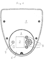
- the in Fig. 1 terminal box shown is arranged on the one end face of an electric motor not shown in detail here, at the other end of the motor shaft exits.
- the terminal box 1 projects beyond the motor not only frontally but also radially and includes an electronic speed controller, as in modern electric motors belongs to the prior art.
- a display and control panel 2 is provided with a display 3 with pressure-sensitive control panels 4 and with a signaling device 5.
- the function of the display 3 and control panel 4 will not be discussed here in detail, it is usual menu-guided control units, as they are well known from the prior art. They insist, as in particular Fig. 2 and 3 illustrate, from a plurality of arranged under a film 6 buttons 7, which are protected under film 6 and can be operated through them. Similarly, the display 3 is protected by the film 6, which is transparent in this area.
- the signal device 5 is covered by a transparent part of the film in such a way that above the signaling device 5, a central window 8 and a circular surrounding this surrounding annular window 9 are formed, which are transparent, whereas the remaining part of the film covered, ie is formed opaque.
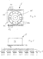
- the signaling device 5 is based on the Fig. 4-6 shown in detail.
- the signaling device 5 has a circuit board 10 on which light-emitting diodes A1-A6 are arranged in an annular arrangement.
- the light-emitting diodes are three-color LEDs with the colors red (R), green (G) and yellow (Y). They are arranged in a common potting, as in the prior art, but are electrically seen from three individual diodes for each of the aforementioned colors.
- a further light-emitting diode A7 is arranged, which is monochrome and green.
- the light-emitting diodes are on the in Fig. 4 soldered partially visible top of the board 10 and led out by printed conductors on the board to lateral connection contacts 11 and 12. As based on Fig. 4 it can be seen, are on one side of the board 10 contacts 11 and led out on the opposite opposite other side contacts 12, which are provided for connection of the light emitting diodes A1 - A7. Of the contacts 11 and 12 are each a ground contact while the others are associated with the light emitting diodes A1 - A7, resulting in the assignment of ten contacts 11 and nine contacts 12 result.
- an annular plastic component 13 On the board 10, an annular plastic component 13 is placed, which has six segments 14 and a central recess 15 in the annular region, which is arranged under the central window 8. Each of the segments 14 receives one of the three-color LEDs A1 - A6, the central recess 15, the monochrome LED A7.
- the segments 14 and the central recess 15 are potted with transparent plastic to the top, so that when installed, for example, one of the diodes A1 - A6 results in a uniform light effect in the associated segment.
- This signal device 5 can be arranged at a suitable location on virtually any circuit boards or other connection components and must by means of the contacts 11 - 12 with a corresponding Control unit to be connected. Based on Fig. 7 It is shown how the ring-shaped light-emitting diodes A1 - A6 are driven to indicate a left-handed motor.
- the light-emitting diodes A1-A6 are each driven in pairs and in pairs opposite one another, ie the light-emitting diode A1 lights up (state 1) simultaneously with the light-emitting diode A4, the light-emitting diode A2 with the light-emitting diode A5 and the light-emitting diode A3 with the light-emitting diode A6.
- the light-emitting diode pair A1, A4 which is turned on for, for example, 0.4 seconds, immediately after ( Fig. 7 ) or slightly overlapping ( Fig. 8 ) the light-emitting diode pair A3, A6 also turned on for 0.4 seconds subsequently.
- the light-emitting diode pair A2, A5 is turned on again for 0.4 seconds, after which the cycle with the switching on of the light-emitting diode pair A1, A4 is repeated. In this way, the impression of a turning left body corresponding to the left then rotating engine.
- the LEDs are switched on and off in the reverse order as described above. Furthermore, at least a rough indication of the speed range can be given over the duty cycle.
- three different switch-on times 0.4, 0.6 and 0.8 seconds can be provided, the duty cycle 0.8 seconds for a lower speed range, the duty cycle 0.6 seconds for a medium speed range and the duty cycle 0.4 seconds stands for a high speed range.
- the red and yellow LEDs remain inactive.
- the yellow LEDs are for a so-called Provided "warning mode" and expediently with the engine running so sequentially that they are in pairs or individually circulating lights, so immediately from the outside is clearly visible that the engine has reached a state that can be used, for example, only occasionally.
- the red light-emitting diodes are basically only intended for impermissible operating states, for example, when the pump is running in the overload range or becomes inadmissibly warm.
- the red light emitting diodes signal that the pump is immediately before the preferably automatically shutdown.
- the red light-emitting diodes can also be illuminated individually or in pairs, depending on the state of the pump, or blinking or standing.
- the central green light emitting diode is provided above for displaying a control mode, which signals that the engine is running in remote control mode, ie, for example, in conjunction with multiple motors, as is common in pump units in larger systems or in individual configuration by remote control.
Landscapes
- Engineering & Computer Science (AREA)
- Power Engineering (AREA)
- Physics & Mathematics (AREA)
- General Physics & Mathematics (AREA)
- Microelectronics & Electronic Packaging (AREA)
- Illuminated Signs And Luminous Advertising (AREA)
- Control Of Electric Motors In General (AREA)
- Control Of Stepping Motors (AREA)
Abstract
Description
- Die Erfindung betrifft einen Elektromotor mit den im Oberbegriff des Anspruchs 1 angegebenen Merkmalen.
- Bei Elektromotoren zählt es zum Stand der Technik, unterschiedliche Betriebszustände des Motors mit einem oder mehreren Leuchtmitteln anzuzeigen. So zählt es beispielsweise bei von einem Elektromotor angetriebenen Kreiselpumpen zum Stand der Technik, den Betrieb der Pumpe durch eine blinkende Leuchtdiode anzuzeigen, wobei die Blinkfrequenz in Abhängigkeit der Drehzahl des Motors variieren kann. Um den Betriebszustand eines solchen Motors zu erfassen, ist es regelmäßig erforderlich, die Betriebsanweisung zu lesen, in der angegeben ist, welche Lichtsymbolik welchem Betriebszustand entspricht. Dies ist vergleichsweise aufwändig, da es stets das Vorhandensein der Betriebsanleitung und die Einsichtnahme darein erfordert, was nachteilig ist.
- Es zählt bei Motoren zum Stand der Technik durch ein dauernd eingeschaltetes Leuchtmittel den Betriebszustand des laufenden Motors anzuzeigen. Es gibt jedoch auch Motoren, bei denen ein blinkendes Leuchtmittel auf den laufenden Zustand des Motors hinweist. Andererseits werden Blinkfunktionen von Leuchtmittel häufig dazu genutzt, um nicht bestimmungsgemäße Betriebszustände, wie beispielsweise den Stillstand des Motors zu signalisieren.
- Vor diesem Stand der Technik liegt der Erfindung die Aufgabe zugrunde, einen gattungsgemäßen Elektromotor so auszubilden, dass zumindest sein Betriebszustand bei laufendem Motor ohne weiteres erkennbar ist.
- Diese Aufgabe wird gemäß der Erfindung durch einen Elektromotor mit den in Anspruch 1 angegebenen Merkmalen gelöst. Vorteilhafte Ausgestaltungen der Erfindung sind in den Unteransprüchen, der nachfolgenden Beschreibung und der Zeichnung angegeben.
- Der erfindungsgemäße Elektromotor weist eine Signaleinrichtung zur Anzeige von mindestens zwei unterschiedlichen Betriebszuständen des Motors auf. Hierzu ist ein elektrisches Leuchtmittel vorgesehen, das bei laufendem Motor blinkend geschaltet ist. Gemäß der Erfindung sind mindestens zwei Leuchtmittel vorgesehen, welche bei laufendem Motor synchron zueinander jedoch zeitlich versetzt blinkend geschaltet sind.
- Grundgedanke der vorliegenden Erfindung ist es, mittels mindestens zweier Leuchtmittel einen Bewegungszustand darzustellen, welcher unmittelbar auf einen laufenden Motor schließen lässt. Mit den mindestens zwei vorzugsweise mehr Leuchtmitteln ist es möglich, wenn diese synchron zueinander jedoch zeitlich versetzt blinkend geschaltet sind, eine Bewegung darzustellen. Insbesondere bei der Verwendung mehrerer Leuchtmittel kann eine Art Lauflicht geschaffen werden, welches zum einen eine wesentlich bessere Erkennbarkeit als Einzelleuchtmittel aufweist und zum anderen eine Bewegung, einen Fluss oder dergleichen darstellt, anhand dessen auch der unbedarfte Beobachter selbsterklärend den Betriebszustand des laufenden Motors erkennt.
- Grundsätzlich kann mit zwei nebeneinander angeordneten Leuchtmittein ein Bewegungseffekt dargestellt werden. Vorteilhaft wird ein solcher jedoch mit mehr als zwei, typischerweise nämlich mit drei oder mehr Leuchtmitteln dargestellt, wobei insbesondere bei Motoren, die eine Rotation ausführen, wie dies bei den meisten Elektromotoranwendungen der Fall ist, eine ringförmige Anordnung der Leuchtmittel zweckmäßig ist, da dann mittels dieser Leuchtmittel die Drehbewegung des Motors darstellbar ist. Wenn, was vorteilhaft ist, drei oder mehr Leuchtmittel ringförmig angeordnet sind, dann sind diese gemäß einer Weiterbildung der Erfindung bei laufendem Motor synchron zueinander jedoch aufeinanderfolgend zeitlich versetzt blinkend geschaltet. D. h. die Leuchtdioden blinken entweder im Uhrzeigersinn aufeinanderfolgend oder im Gegenuhrzeigersinn aufeinanderfolgend. Dabei kann eine gewisse Überlappung der Einschaltzeiten vorteilhaft sein, um ein natürliches Aussehen der Anzeige zu erreichen, also ein natürliches Aussehen der zu symbolisierenden Drehbewegung darzustellen. Wie weit eine Überlappung erfolgt oder nicht und in welchem Takt das Blinken erfolgt, kann auf einfache Weise ermittelt werden und ist für den jeweiligen Anwendungszweck von Fall zu Fall zu wählen. So kann durch unterschiedliche Blinkgeschwindigkeiten eine gewisse Drehzahldarstellung erfolgen, d. h. bei einem langsam laufenden Motor erfolgt ein langsames und bei einem schnell laufenden Motor ein schnelles Blinken. In analoger Weise kann bei ringförmiger Anordnung die Drehrichtung des Motors dargestellt werden, so kann ein Lauflichteffekt im Uhrzeigersinn oder gegen den Uhrzeigersinn erfolgen, je nachdem ob die Motorwelle im Uhrzeigersinn oder gegen den Uhrzeigersinn dreht.
- Es hat sich herausgestellt, dass eine besonders natürlich und gleichmäßig ruhig wirkende Anzeige dann erzielbar ist, wenn sechs Leuchtmittel ringförmig angeordnet sind, die bei laufendem Motor synchron zueinander jedoch paarweise aufeinanderfolgend zeitlich versetzt blinkend geschaltet sind. Bei einer solchen Anordnung sind jeweils zwei diametral gegenüberliegend im Ring angeordnete Leuchtmittel eingeschaltet bzw. wandert dieses eingeschaltete Leuchtmittelpaar in Drehrichtung rechts- oder linksherum, was eine besonders gute Ablesbarkeit bedingt. Schon von größerer Entfernung kann daher bei entsprechender Anordnung einer solchen Signaleinrichtung am Motor festgestellt werden, ob dieser bestimmungsgemäß läuft, gegebenenfalls auch in welcher Richtung und mit welcher Drehzahl, wobei hinsichtlich der Drehzahl typischerweise Tendenzen wie untere Drehzahl, mittlere Drehzahl, hohe Drehzahl anzeigbar sind. Die paarweise Leuchtmittelanordnung hat darüber hinaus den Vorteil, dass bei Ausfall eines Leuchtmittels nicht die ganze Anzeige ausfällt sondern dann für dieses Leuchtmittelpaar mit einem Leuchtmittel noch in Betrieb bleibt und auch gut erkennbar bleibt.
- Grundsätzlich können die Leuchtmittel in einem dreieckigen, ovalen, rechteckigen, quadratischen Ring oder in anderer Ringform angeordnet werden. Besonders gut erkennbar sind sie jedoch wenn sie kreisringförmig angeordnet sind.
- Bei der gleichzeitigen Ansteuerung von zwei Leuchtmitteln ist es besonders vorteilhaft, wenn diese diametral angeordnet sind, da dies die Erkennbarkeit und die natürliche Darstellung einer Drehbewegung fördert.
- Vorteilhaft kann innerhalb des Leuchtmittelrings gemäß einer Weiterbildung der Erfindung ein zentrales Leuchtmittel angeordnet sein. Dieses zentrale Leuchtmittel kann beispielsweise dazu dienen, den Einschaltzustand darzustellen, d. h. darzustellen, ob der Elektromotor eingeschaltet ist oder nicht oder ob am Elektromotor Spannung anliegt oder nicht. Alternativ kann hiermit auch ein Fernsteuerzustand oder eine andere Betriebseigenschaft angezeigt werden.
- Wenn weitere Betriebszustände angezeigt werden sollen, wie beispielsweise Temperatur, Druck oder dergleichen, kann es erforderlich oder zweckmäßig sein, hierfür weitere Leuchtmittel vorzusehen. Gemäß einer vorteilhaften Weiterbildung der Erfindung sind diese Leuchtmittel dann innerhalb eines oder mehrerer vorzugsweise konzentrischer Ringe angeordnet. Eine solche Anordnung ist zum einen optisch ansprechend, zum anderen raumsparend.
- Vorteilhaft erfolgt die Schaltung der Leuchtmittel so, dass bei eingeschaltetem stehenden Motor mindestens ein Leuchtmittel oder Leuchtmittelpaar dauerhaft eingeschaltet ist. Insbesondere bei ringförmiger Anordnung der Leuchtmittel oder Leuchtmittelpaare kann dadurch erkennbar symbolisiert werden, dass der Motor steht.
- Alternativ oder zusätzlich kann gemäß einer Weiterbildung der Erfindung auch nur ein Leuchtmittel oder ein Leuchtmittelpaar im Gleichtaktblinken geschaltet sein, wenn bei eingeschaltetem Motor der Motor steht. Dies wird zweckmäßigerweise dann so geschaltet, wenn die stehende Motorfunktion nicht bestimmungsgemäß ist, also beispielsweise bei festsitzendem Rotor oder Überlastzustand.
- Grundsätzlich können für den erfindungsgemäßen Elektromotor unterschiedliche Leuchtmittel zum Einsatz kommen, besonders vorteilhaft ist es jedoch, sämtliche Leuchtmittel als Leuchtdioden auszubilden, da diese kostengünstig verfügbar sind, einen geringen Energieverbrauch aufweisen und lange Zeit stabil arbeiten.
- Gemäß einer vorteilhaften Weiterbildung erfolgt die Betriebszustandskennzeichnung nicht nur durch Darstellung der Motorbewegung sondern vorzugsweise zusätzlich durch Farbdarstellungen. Hierzu sind gemäß einer Weiterbildung der Erfindung Dreifarbenleuchtdioden vorgesehen, vorzugsweise in den Farben rot, grün und gelb. Alternativ können solche Dreifarbenleuchtdioden auch durch drei einzelne Leuchtdioden gebildet sein. Die Farben rot, grün und gelb sind selbsterklärend und entsprechen der internationalen Ampelkennzeichnung, können also bei geeigneter Verwendung selbsterklärend Betriebszustände darstellen. Dabei sind bevorzugt die Leuchtdioden grün geschaltet für bestimmungsgemäße Betriebszustände des Motors. Für nicht bestimmungsgemäße Betriebszustände des Motors sind vorteilhaft die Leuchtdioden rot geschaltet. Die Schaltung der gelben Leuchtdioden kann für Betriebszustände Verwendung finden, die beispielsweise gerade noch bestimmungsgemäß sind, jedoch nicht auf Dauer. So kann beispielsweise bei kurzzeitiger Überlastung des Motors dies durch die Einschaltung der gelben Leuchtdioden symbolisiert werden, wobei nach Überschreiten der zulässigen Belastungszeit dann schließlich die roten Leuchtdioden eingeschaltet werden, um den nicht bestimmungsgemäßen Zustand oder das unmittelbar bevorstehende Abschalten des Motor zu kennzeichnen.
- Vorteilhaft werden die Leuchtmittel zur Anzeige von Betriebszuständen an einer Stirnseite des Motorgehäuses angebracht, grundsätzlich können diese jedoch auch an anderer Stelle oder auch entfernt vom Motor angebracht sein. So ist es gemäß einer Weiterbildung der Erfindung denkbar, dass die vorbeschriebene Anordnung von Leuchtmitteln zur Anzeige von unterschiedlichen Betriebszuständen nicht am Motor sondern am Bedienteil, das gegebenenfalls drahtlos angebunden ist, zusätzlich oder auch ausschließlich angeordnet sein.
- Besonders vorteilhaft wird der erfindungsgemäße Elektromotor mit seiner Signaleinrichtung zur Betriebszustandsanzeige im Zusammenhang mit einem Kreiselpumpenaggregat eingesetzt, wobei die Leuchtmittel an der von der Pumpe abgewandten und quer zur Motorachse angeordneten Stirnseite oder an einem am Motor angeordneten Klemmenkasten angeordnet sind. Besonders vorteilhaft wird eine solche Signaleinrichtung bei sogenannten Nassläufern einzusetzen sein, d. h. bei Motoren, insbesondere von Umwälzpumpen, bei denen der Rotor in einem Spaltrohr läuft, welches flüssigkeitsgefüllt ist und bei dem daher typischerweise die rotierenden Teile des Motors nicht sichtbar sind. Gerade bei solchen Motoren ist das Vorsehen einer solchen Betriebszustandsanzeige von Vorteil, um den Motorzustand, insbesondere die Bewegung des Rotors, erkennbar zu machen. So kann vorteilhaft bei Heizungsumwälzpumpen oder anderen Umwälzpumpen eine Signaleinrichtung der vorbeschriebenen Art vorgesehen sein. Eine solche Signaleinrichtung ist insbesondere von Vorteil an Orten, die schlecht zugänglich oder ungenügend beleuchtet sind, wie dies beispielsweise in Heizungskellern, Pumpensümpfen, Fäkalienhebeanlagen und dergleichen häufig der Fall ist. Insbesondere bei diesen Anwendungen ist eine solche selbsterklärende Signaleinrichtung von Vorteil, da Bedienungsanleitungen meist nicht zugänglich oder zumindest schlecht lesbar sind und Aufdrucke am Aggregat selbst aufgrund der häufig herrschenden rauen Umwelteinflüsse in Mitleidenschaft gezogen sein können.
- Die Signaleinrichtung zur Anzeige von mindestens zwei unterschiedlichen Betriebszuständen des Motors ist anhand eines in der Zeichnung dargestellten Ausführungsbeispiels dargestellt, welches eine Signaleinrichtung am Klemmenkasten eines Motors beispielhaft zeigt. Es zeigen:
- Fig. 1
- die Stirnansicht eines Klemmenkastens eines Elektromotors,
- Fig. 2
- die Ansicht gemäß
Fig. 1 mit teilweise entfernter Abdeckfolie, - Fig. 3
- die die Signaleinrichtung, eine Anzeige und Schaltmittel umfassende Platine,
- Fig. 4
- eine Draufsicht auf die Signaleinrichtung,
- Fig. 5
- eine Seitenansicht der Signaleinrichtung,
- Fig. 6
- ein elektrisches Schaltbild der Signaleinrichtung,
- Fig. 7
- ein Diagramm, welches die Einschaltzeiten der ringförmig angeordneten Leuchtmittel zueinander darstellt und
- Fig. 8
- ein Schaltbild in Darstellung gemäß
Fig. 7 mit überlappenden Einschaltzeiten. - Der in
Fig. 1 dargestellte Klemmenkasten ist an der einen Stirnseite eines hier nicht im Einzelnen dargestellten Elektromotors angeordnet, an dessen anderem Ende die Motorwelle austritt. Der Klemmenkasten 1 überragt den Motor nicht nur stirnseitig sondern auch radial und beinhaltet einen elektronischen Drehzahlsteller, wie dies bei modernen Elektromotoren zum Stand der Technik zählt. - Am Klemmenkasten 1 ist ein Anzeige- und Bedienfeld 2 vorgesehen mit einem Display 3 mit druckempfindlichen Bedienfeldern 4 sowie mit einer Signaleinrichtung 5. Auf die Funktion von Display 3 und Bedienfeld 4 soll hier nicht im einzelnen eingegangen werden, es handelt sich um übliche menugeführte Bedieneinheiten, wie sie aus dem Stand der Technik hinlänglich bekannt sind. Sie bestehen, wie insbesondere
Fig. 2 und3 veranschaulichen, aus mehreren unter einer Folie 6 angeordneten Tastern 7, die geschützt unter Folie 6 liegen und durch diese hindurch bedienbar sind. Ebenso ist das Display 3 durch die Folie 6 geschützt, die in diesem Bereich durchsichtig ist. Auch die Signaleinrichtung 5 ist durch einen durchsichtigen Teil der Folie überdeckt und zwar so, dass über der Signaleinrichtung 5 ein zentrales Fenster 8 und ein dieses mit Abstand umgebendes ringförmiges Fenster 9 gebildet sind, die durchsichtig sind, wohingegen der übrige Teil der Folie abgedeckt, d. h. undurchsichtig ausgebildet ist. - Die Signaleinrichtung 5 ist anhand der
Fig. 4 - 6 im einzelnen dargestellt. Die Signaleinrichtung 5 weist eine Platine 10 auf, auf der in kreisringförmiger Anordnung 6 Leuchtdioden A1 - A6 angeordnet sind. Die Leuchtdioden sind Dreifarbenleuchtdioden mit den Farben rot (R), grün (G) und gelb (Y). Sie sind in einem gemeinsamen Vergussgehäuse angeordnet, wie dies zum Stand der Technik zählt, bestehen jedoch elektrisch gesehen aus drei Einzeldioden für jede der vorgenannten Farben. Im Zentrum der ringförmigen Anordnung ist eine weitere Leuchtdiode A7 angeordnet, welche einfarbig und grün ist. - Die Leuchtdioden sind auf der in
Fig. 4 teilweise sichtbaren Oberseite der Platine 10 aufgelötet und durch Leiterbahnen auf der Platine zu seitlichen Anschlusskontakten 11 und 12 herausgeführt. Wie anhand vonFig. 4 ersichtlich ist, sind an einer Seite der Platine 10 Kontakte 11 und an der abgewandt gegenüberliegend anderen Seite Kontakte 12 herausgeführt, welche zum Anschluss der Leuchtdioden A1 - A7 vorgesehen sind. Von den Kontakten 11 und 12 sind jeweils einer ein Massekontakt während die anderen den Leuchtdioden A1 - A7 zugeordnet sind, woraus sich die Belegung von zehn Kontakten 11 bzw. neun Kontakten 12 ergeben. - Auf der Platine 10 ist ein ringförmiges Kunststoffbauteil 13 aufgesetzt, welches in dem ringförmigen Bereich, der unter dem zentralen Fenster 8 geordnet ist, sechs Segmente 14 sowie eine zentrale Ausnehmung 15 aufweist. Jedes der Segmente 14 nimmt eine der Dreifarbenleuchtdioden A1 - A6 auf, die zentrale Ausnehmung 15 die einfarbige Leuchtdiode A7. Die Segmente 14 und die zentrale Ausnehmung 15 sind mit durchsichtigem Kunststoff bis zur Oberseite vergossen, sodass sich in eingebautem Zustand beim Einschalten beispielsweise einer der Dioden A1 - A6 eine gleichmäßige Lichtwirkung in dem zugehörigen Segment ergibt.
- Diese Signaleinrichtung 5 kann an geeigneter Stelle auf quasi beliebigen Platinen oder auch anderen Anschlussbauteilen angeordnet werden und muss mittels der Kontakte 11 - 12 mit einem entsprechenden Steuergerät verbunden werden. Anhand von
Fig. 7 ist dargestellt, wie die ringförmig angeordneten Leuchtdioden A1 - A6 angesteuert werden, um einen linksdrehenden Motor anzuzeigen. Dabei sind die Leuchtdioden A1 - A6 jeweils paarweise angesteuert und zwar paarweise gegenüberliegend, d. h. die Leuchtdiode A1 leuchtet (Zustand 1) gleichzeitig mit der Leuchtdiode A4, die Leuchtdiode A2 mit der Leuchtdiode A5 und die Leuchtdiode A3 mit der Leuchtdiode A6. Beginnend mit dem Leuchtdiodenpaar A1, A4, das für beispielsweise 0,4 Sekunden eingeschaltet wird, wird unmittelbar anschließend (Fig. 7 ) oder leicht überlappend (Fig. 8 ) das Leuchtdiodenpaar A3, A6 ebenfalls für 0,4 Sekunden darauffolgend eingeschaltet. Nach Ablauf dieser 0,4 Sekunden oder kurz überlappend wird das Leuchtdiodenpaar A2, A5 für wiederum 0,4 Sekunden eingeschaltet, nach deren Ablauf sich der Zyklus mit Einschaltung des Leuchtdiodenpaares A1, A4 wiederholt. Auf diese Weise entsteht der Eindruck eines sich links drehenden Körpers entsprechend dem sich dann links drehenden Motor. - Bei rechts drehendem Motor erfolgt die Ein- und Ausschaltung der Leuchtdioden in umgekehrter Reihenfolge wie vorbeschrieben. Weiterhin kann über die Einschaltdauer ein zumindest grober Hinweis auf den Drehzahlbereich gegeben sein. So können beispielsweise drei verschiedene Einschaltdauern 0,4, 0,6 und 0,8 Sekunden vorgesehen sein, wobei die Einschaltdauer 0,8 Sekunden für einen unteren Drehzahlbereich, die Einschaltdauer 0,6 Sekunden für einen mittleren Drehzahlbereich und die Einschaltdauer 0,4 Sekunden für einen hohen Drehzahlbereich steht.
- Bei bestimmungsgemäßen Betrieb werden ausschließlich die grünen Leuchtdioden A1 - A6 geschaltet, die roten und gelben Leuchtdioden verbleiben inaktiv. Bei stehendem Rotor und eingeschalteter Spannungsversorgung leuchtet jeweils nur ein Paar der grünen Leuchtdioden A1 - A6. Die gelben Leuchtdioden sind für einen sogenannten "warning mode" vorgesehen und bei laufendem Motor zweckmäßigerweise so nacheinander angesteuert, dass diese paarweise oder einzeln umlaufend leuchtend sind, sodass von außen sofort deutlich sichtbar wird, dass der Motor einen Zustand erreicht hat, der beispielsweise nur zeitweise befahren werden kann. Die roten Leuchtdioden sind grundsätzlich nur für unzulässige Betriebszustände vorgesehen, beispielsweise wenn die Pumpe im Überlastbereich läuft oder unzulässig warm wird. Die roten Leuchtdioden signalisieren, dass die Pumpe unmittelbar vor dem vorzugsweise automatisch erfolgenden Abschalten steht. Auch die roten Leuchtdioden können einzeln oder paarweise je nach Zustand der Pumpe umlaufend oder stehend leuchten oder blinken.
- Die zentrale gründe Leuchtdiode ist vorstehend zur Anzeige eines Steuermodus vorgesehen, welcher signalisiert, dass der Motor im Fernsteuermodus läuft, d. h. beispielsweise im Verbund mit mehreren Motoren, wie dies bei Pumpenaggregaten in größeren Anlagen üblich ist oder auch in Einzelkonfiguration per Fernsteuerung.
-
- 1
- Klemmenkasten
- 2
- Anzeige- und Bedienfeld
- 3
- Display
- 4
- Bedienfeld
- 5
- Signaleinrichtung
- 6
- Folie
- 7
- Taster
- 8
- Zentrales Fenster
- 9
- Ringförmiges Fenster
- 10
- Platine
- 11
- Kontakte
- 12
- Kontakte
- 13
- Kunststoffbauteil
- 14
- Segmente
- 15
- Zentrale Ausnehmung
- A1 - A6
- Leuchtdioden dreifarbig R, G, Y
- A7
- Leuchtdiode einfarbig G
- R
- rot
- G
- grün
- Y
- gelb
Claims (18)
- Bedienteil für einen Elektromotor, wobei das Bedienteil eine Signaleinrichtung (5) zur Anzeige von mindestens zwei unterschiedlichen Betriebszuständen des Motors aufweist, mit mindestens einem elektrischen Leuchtmittel (A1 - A6), das bei laufendem Motor blinkend geschaltet ist, dadurch gekennzeichnet, dass mindestens zwei Leuchtmittel (A1 - A6) vorgesehen sind, welche bei laufendem Motor synchron zueinander jedoch zeitlich versetzt blinkend geschaltet sind.
- Bedienteil nach Anspruch 1, dadurch gekennzeichnet, dass drei oder mehr Leuchtmittel (A1 - A6) ringförmig angeordnet sind und bei laufendem Motor synchron zueinander jedoch aufeinanderfolgend zeitlich versetzt blinkend geschaltet sind.
- Bedienteil nach Anspruch 1 oder 2, dadurch gekennzeichnet, dass sechs Leuchtmittel (A1 - A6) ringförmig angeordnet sind, die bei laufendem Motor synchron zueinander jedoch paarweise aufeinanderfolgend zeitlich versetzt blinkend geschaltet sind.
- Bedienteil nach einem der vorhergehenden Ansprüche, dadurch gekennzeichnet, dass das Bedienteil drahtlos an den Elektromotor angebunden ist.
- Bedienteil nach einem der vorhergehenden Ansprüche, dadurch gekennzeichnet, dass die Leuchtmittel (A1 - A6) kreisringförmig angeordnet sind.
- Bedienteil nach einem der vorhergehenden Ansprüche, dadurch gekennzeichnet, dass die Leuchtmittel in dreieckförmiger Ringkonfiguration angeordnet sind.
- Bedienteil nach einem der vorhergehenden Ansprüche, dadurch gekennzeichnet, dass die Leuchtmittel in vier- oder mehreckförmiger Konfiguration angeordnet sind.
- Bedienteil nach einem der vorhergehenden Ansprüche, dadurch gekennzeichnet, dass ein Leuchtmittelpaar (A1, A4; A2, A5; A3, A6) durch zwei diametral angeordnete Leuchtmittel gebildet ist.
- Bedienteil nach einem der vorhergehenden Ansprüche, dadurch gekennzeichnet, dass innerhalb des Leuchtmittelringes (A1 - A6) ein zentrales Leuchtmittel (A7) angeordnet ist.
- Bedienteil nach einem der vorhergehenden Ansprüche, dadurch gekennzeichnet, dass weitere Leuchtmittel in einem oder mehreren vorzugsweise konzentrischen Ringen angeordnet sind.
- Bedienteil nach einem der vorhergehenden Ansprüche, dadurch gekennzeichnet, dass bei eingeschaltetem stehenden Motor mindestens ein Leuchtmittel (A1 - A6) oder Leuchtmittelpaar dauerhaft eingeschaltet ist.
- Bedienteil nach einem der vorhergehenden Ansprüche, dadurch gekennzeichnet, dass bei eingeschaltetem stehendem Motor nur ein Leuchtmittel (A1 - A6) blinkend oder nur ein Leuchtmittelpaar im Gleichtakt blinkend geschaltet ist.
- Bedienteil nach einem der vorhergehenden Ansprüche, dadurch gekennzeichnet, dass ein Leuchtmittel, vorzugsweise alle Leuchtmittel durch Leuchtdioden (A1 - A6) gebildet sind.
- Bedienteil nach einem der vorhergehenden Ansprüche, dadurch gekennzeichnet, dass die Leuchtdioden durch Dreifarbenleuchtdioden (A1 - A6) gebildet sind, vorzugsweise der Farben rot, grün und gelb.
- Bedienteil nach einem der vorhergehenden Ansprüche, dadurch gekennzeichnet, dass bei bestimmungsgemäßen Betriebszuständen des Motors die Leuchtdioden (A1 - A6) grün geschaltet sind.
- Bedienteil nach einem der vorhergehenden Ansprüche, dadurch gekennzeichnet, dass bei nicht bestimmungsgemäßen Betriebszuständen des Motors die Leuchtdioden rot (A1 - A6) geschaltet sind.
- Bedienteil nach einem der vorhergehenden Ansprüche, dadurch gekennzeichnet, dass er Teil eines Kreispumpenaggregates bildet und die Leuchtmittel an der von der Pumpe abgewandten und quer zur Motorachse angeordneten Stirnseite oder an einem am Motor angeordneten Klemmenkasten (1) angeordnet sind.
- Elektromotor mit einem Bedienteil nach einem der vorhergehenden Ansprüche.
Priority Applications (1)
| Application Number | Priority Date | Filing Date | Title |
|---|---|---|---|
| EP19152090.7A EP3496245B1 (de) | 2012-02-08 | 2012-02-08 | Elektromotor |
Applications Claiming Priority (2)
| Application Number | Priority Date | Filing Date | Title |
|---|---|---|---|
| EP19152090.7A EP3496245B1 (de) | 2012-02-08 | 2012-02-08 | Elektromotor |
| EP12154489.4A EP2626986A1 (de) | 2012-02-08 | 2012-02-08 | Elektromotor mit einer Signaleinrichtung |
Related Parent Applications (1)
| Application Number | Title | Priority Date | Filing Date |
|---|---|---|---|
| EP12154489.4A Division EP2626986A1 (de) | 2012-02-08 | 2012-02-08 | Elektromotor mit einer Signaleinrichtung |
Publications (3)
| Publication Number | Publication Date |
|---|---|
| EP3496245A1 true EP3496245A1 (de) | 2019-06-12 |
| EP3496245C0 EP3496245C0 (de) | 2024-09-18 |
| EP3496245B1 EP3496245B1 (de) | 2024-09-18 |
Family
ID=47630265
Family Applications (2)
| Application Number | Title | Priority Date | Filing Date |
|---|---|---|---|
| EP12154489.4A Ceased EP2626986A1 (de) | 2012-02-08 | 2012-02-08 | Elektromotor mit einer Signaleinrichtung |
| EP19152090.7A Active EP3496245B1 (de) | 2012-02-08 | 2012-02-08 | Elektromotor |
Family Applications Before (1)
| Application Number | Title | Priority Date | Filing Date |
|---|---|---|---|
| EP12154489.4A Ceased EP2626986A1 (de) | 2012-02-08 | 2012-02-08 | Elektromotor mit einer Signaleinrichtung |
Country Status (4)
| Country | Link |
|---|---|
| US (1) | US9467025B2 (de) |
| EP (2) | EP2626986A1 (de) |
| CN (2) | CN110086297B (de) |
| WO (1) | WO2013117401A2 (de) |
Families Citing this family (4)
| Publication number | Priority date | Publication date | Assignee | Title |
|---|---|---|---|---|
| WO2016078686A1 (en) | 2014-11-17 | 2016-05-26 | Grundfos Holding A/S | Method for authorising a handheld communication device access to a pump unit |
| WO2016086986A1 (en) | 2014-12-03 | 2016-06-09 | Grundfos Holding A/S | An electronic converter unit for retrofitting to an external part of a housing of a pump unit |
| WO2017132833A1 (zh) * | 2016-02-02 | 2017-08-10 | 深圳市大疆创新科技有限公司 | 控制方法、系统,以及电调及采用该电调的动力套装、无人飞行器 |
| DE102021000932A1 (de) * | 2021-02-22 | 2022-08-25 | KSB SE & Co. KGaA | Pumpe mit Bedienfeld |
Citations (5)
| Publication number | Priority date | Publication date | Assignee | Title |
|---|---|---|---|---|
| JPS57144466A (en) * | 1981-03-02 | 1982-09-07 | Taiho Kiko Kk | Pilot lamp of electronic meter |
| US5237310A (en) * | 1991-01-28 | 1993-08-17 | Inco Limited | Pump monitor |
| JPH0618383U (ja) * | 1992-08-14 | 1994-03-08 | 日産ディーゼル工業株式会社 | ウインチモニター装置 |
| JP2004101498A (ja) * | 2002-09-05 | 2004-04-02 | Inko Lee | 電動機の回転方向検出装置及びその方法 |
| CA2540610A1 (en) * | 2005-08-09 | 2007-02-09 | Metropolitan Industries, Inc. | Pump monitoring system |
Family Cites Families (13)
| Publication number | Priority date | Publication date | Assignee | Title |
|---|---|---|---|---|
| US3789387A (en) * | 1972-08-16 | 1974-01-29 | J Hurst | Dynamic motion display system |
| JPS5111084U (de) * | 1974-07-10 | 1976-01-27 | ||
| GB2276463A (en) * | 1993-03-23 | 1994-09-28 | Vickers Inc | Detection of phase rotation sequence |
| US6874909B2 (en) * | 2003-01-13 | 2005-04-05 | Carl R. Vanderschuit | Mood-enhancing illumination apparatus |
| US6480116B1 (en) * | 2001-06-26 | 2002-11-12 | Trojan Technology, Inc. | Method and apparatus for showing special characters or figures on a rotating disk |
| CN1402202A (zh) * | 2001-08-24 | 2003-03-12 | 英业达集团(上海)电子技术有限公司 | 便携式电子设备的发光二极管信息显示装置 |
| JP3616961B2 (ja) * | 2001-10-02 | 2005-02-02 | 株式会社ニチフ端子工業 | 撹拌扇の動作確認装置 |
| AU2004222860B2 (en) * | 2003-10-28 | 2010-02-18 | Pentair Pool Products, Inc. | Microprocessor controlled time domain switching of color-changing lights |
| US7192040B2 (en) * | 2003-12-17 | 2007-03-20 | Shouchun Xie | Drive mechanism for vehicle |
| CN100591923C (zh) * | 2005-06-22 | 2010-02-24 | 富准精密工业(深圳)有限公司 | 风扇转速显示装置 |
| US7579959B2 (en) * | 2005-07-11 | 2009-08-25 | Samsung Electronics Co., Ltd. | Image recording apparatus for displaying state of operation by LED and method for displaying the state of operation thereof |
| CN101737765A (zh) * | 2008-11-26 | 2010-06-16 | 鸿富锦精密工业(深圳)有限公司 | 电子装置工作状态指示灯 |
| CN201595643U (zh) * | 2009-11-26 | 2010-10-06 | 贺友义 | 带有智能灯光显示的榨汁、搅拌机 |
-
2012
- 2012-02-08 EP EP12154489.4A patent/EP2626986A1/de not_active Ceased
- 2012-02-08 EP EP19152090.7A patent/EP3496245B1/de active Active
-
2013
- 2013-01-17 US US14/377,254 patent/US9467025B2/en active Active
- 2013-01-17 WO PCT/EP2013/050860 patent/WO2013117401A2/de not_active Ceased
- 2013-01-17 CN CN201910092567.9A patent/CN110086297B/zh active Active
- 2013-01-17 CN CN201380008637.9A patent/CN104335462B/zh active Active
Patent Citations (5)
| Publication number | Priority date | Publication date | Assignee | Title |
|---|---|---|---|---|
| JPS57144466A (en) * | 1981-03-02 | 1982-09-07 | Taiho Kiko Kk | Pilot lamp of electronic meter |
| US5237310A (en) * | 1991-01-28 | 1993-08-17 | Inco Limited | Pump monitor |
| JPH0618383U (ja) * | 1992-08-14 | 1994-03-08 | 日産ディーゼル工業株式会社 | ウインチモニター装置 |
| JP2004101498A (ja) * | 2002-09-05 | 2004-04-02 | Inko Lee | 電動機の回転方向検出装置及びその方法 |
| CA2540610A1 (en) * | 2005-08-09 | 2007-02-09 | Metropolitan Industries, Inc. | Pump monitoring system |
Also Published As
| Publication number | Publication date |
|---|---|
| US9467025B2 (en) | 2016-10-11 |
| CN110086297A (zh) | 2019-08-02 |
| CN104335462B (zh) | 2019-11-26 |
| WO2013117401A2 (de) | 2013-08-15 |
| CN104335462A (zh) | 2015-02-04 |
| EP2626986A1 (de) | 2013-08-14 |
| WO2013117401A3 (de) | 2014-09-04 |
| EP3496245C0 (de) | 2024-09-18 |
| US20150022039A1 (en) | 2015-01-22 |
| CN110086297B (zh) | 2021-11-16 |
| EP3496245B1 (de) | 2024-09-18 |
Similar Documents
| Publication | Publication Date | Title |
|---|---|---|
| DE202019105112U1 (de) | Schraubenanzugswerkzeug | |
| WO2013087670A2 (de) | Verfahren und vorrichtung zur darstellung einer information über einen energiespeicher eines fahrzeugs | |
| EP2626986A1 (de) | Elektromotor mit einer Signaleinrichtung | |
| EP2565461B1 (de) | Pumpenaggregat | |
| DE102016113341A1 (de) | Stromzähler und Stromzählertestgerät | |
| EP2334218B1 (de) | Küchengerät mit motordrehzahlanzeige | |
| DE212015000276U1 (de) | Zustandsanzeigevorrichtung für die Industriemaschine und Leistungswandlungsvorrichtung | |
| DE202014102379U1 (de) | Eine Flackernanlage für elektronische und elektrische Imitationskerzen | |
| EP2522202B1 (de) | Produktionsmaschine mit einer betriebszustandswarnleuchtvorrichtung | |
| DE202012013656U1 (de) | Elektromotor | |
| DE202013104775U1 (de) | Eine LED-Lichterkette und Kontroller der LED-Lichterkette | |
| DE2150829C3 (de) | Digitaluhr mit einer Zeitanzeige durch elektrische Lampen | |
| DE202011109497U1 (de) | Pumpenaggregat | |
| DE102006015175B4 (de) | Blitzlicht-Warnleuchtgerät | |
| DE102019109182A1 (de) | Segmentierte Leuchtanzeige | |
| DE102012200154B4 (de) | Anzeigegerät für ein Kraftfahrzeug | |
| CH702356B1 (de) | Leuchtreklame, insbesondere Leuchtbuchstabe. | |
| EP1772933B1 (de) | Hochspannungselektrodenanordnung | |
| DE2710146A1 (de) | Rotierende reklame- oder signalflaeche | |
| DE102009002696A1 (de) | Beleuchtungseinrichtung mit Standlicht | |
| EP3022809B1 (de) | Steckvorrichtung | |
| DE643355C (de) | Einrichtung zur elektrischen Beleuchtung, insbesondere einer Buehne | |
| DE102018008389A1 (de) | Kreiselpumpenaggregat mit Bedienelement | |
| DE102009002125A1 (de) | Ein LED-Displaygerät zum Darstellen von Mustern auf einem rotierenden Gegenstand durch Lichtabtastung | |
| DE2357502C3 (de) | Leuchtanzeige für Rundfunk- oder Fernsehempfänger |
Legal Events
| Date | Code | Title | Description |
|---|---|---|---|
| PUAI | Public reference made under article 153(3) epc to a published international application that has entered the european phase |
Free format text: ORIGINAL CODE: 0009012 |
|
| STAA | Information on the status of an ep patent application or granted ep patent |
Free format text: STATUS: THE APPLICATION HAS BEEN PUBLISHED |
|
| AC | Divisional application: reference to earlier application |
Ref document number: 2626986 Country of ref document: EP Kind code of ref document: P |
|
| AK | Designated contracting states |
Kind code of ref document: A1 Designated state(s): AL AT BE BG CH CY CZ DE DK EE ES FI FR GB GR HR HU IE IS IT LI LT LU LV MC MK MT NL NO PL PT RO RS SE SI SK SM TR |
|
| STAA | Information on the status of an ep patent application or granted ep patent |
Free format text: STATUS: REQUEST FOR EXAMINATION WAS MADE |
|
| 17P | Request for examination filed |
Effective date: 20191212 |
|
| RBV | Designated contracting states (corrected) |
Designated state(s): AL AT BE BG CH CY CZ DE DK EE ES FI FR GB GR HR HU IE IS IT LI LT LU LV MC MK MT NL NO PL PT RO RS SE SI SK SM TR |
|
| STAA | Information on the status of an ep patent application or granted ep patent |
Free format text: STATUS: EXAMINATION IS IN PROGRESS |
|
| 17Q | First examination report despatched |
Effective date: 20210903 |
|
| GRAP | Despatch of communication of intention to grant a patent |
Free format text: ORIGINAL CODE: EPIDOSNIGR1 |
|
| STAA | Information on the status of an ep patent application or granted ep patent |
Free format text: STATUS: GRANT OF PATENT IS INTENDED |
|
| GRAJ | Information related to disapproval of communication of intention to grant by the applicant or resumption of examination proceedings by the epo deleted |
Free format text: ORIGINAL CODE: EPIDOSDIGR1 |
|
| INTG | Intention to grant announced |
Effective date: 20240214 |
|
| STAA | Information on the status of an ep patent application or granted ep patent |
Free format text: STATUS: EXAMINATION IS IN PROGRESS |
|
| INTC | Intention to grant announced (deleted) | ||
| GRAP | Despatch of communication of intention to grant a patent |
Free format text: ORIGINAL CODE: EPIDOSNIGR1 |
|
| STAA | Information on the status of an ep patent application or granted ep patent |
Free format text: STATUS: GRANT OF PATENT IS INTENDED |
|
| INTG | Intention to grant announced |
Effective date: 20240503 |
|
| GRAS | Grant fee paid |
Free format text: ORIGINAL CODE: EPIDOSNIGR3 |
|
| GRAA | (expected) grant |
Free format text: ORIGINAL CODE: 0009210 |
|
| STAA | Information on the status of an ep patent application or granted ep patent |
Free format text: STATUS: THE PATENT HAS BEEN GRANTED |
|
| AC | Divisional application: reference to earlier application |
Ref document number: 2626986 Country of ref document: EP Kind code of ref document: P |
|
| AK | Designated contracting states |
Kind code of ref document: B1 Designated state(s): AL AT BE BG CH CY CZ DE DK EE ES FI FR GB GR HR HU IE IS IT LI LT LU LV MC MK MT NL NO PL PT RO RS SE SI SK SM TR |
|
| REG | Reference to a national code |
Ref country code: GB Ref legal event code: FG4D Free format text: NOT ENGLISH |
|
| REG | Reference to a national code |
Ref country code: CH Ref legal event code: EP |
|
| REG | Reference to a national code |
Ref country code: IE Ref legal event code: FG4D Free format text: LANGUAGE OF EP DOCUMENT: GERMAN |
|
| REG | Reference to a national code |
Ref country code: DE Ref legal event code: R096 Ref document number: 502012017281 Country of ref document: DE |
|
| U01 | Request for unitary effect filed |
Effective date: 20241008 |
|
| U07 | Unitary effect registered |
Designated state(s): AT BE BG DE DK EE FI FR IT LT LU LV MT NL PT RO SE SI Effective date: 20241028 |
|
| U1O | Appointed representative for the unitary patent procedure deleted after the registration of the unitary effect | ||
| PG25 | Lapsed in a contracting state [announced via postgrant information from national office to epo] |
Ref country code: NO Free format text: LAPSE BECAUSE OF FAILURE TO SUBMIT A TRANSLATION OF THE DESCRIPTION OR TO PAY THE FEE WITHIN THE PRESCRIBED TIME-LIMIT Effective date: 20241218 |
|
| PG25 | Lapsed in a contracting state [announced via postgrant information from national office to epo] |
Ref country code: GR Free format text: LAPSE BECAUSE OF FAILURE TO SUBMIT A TRANSLATION OF THE DESCRIPTION OR TO PAY THE FEE WITHIN THE PRESCRIBED TIME-LIMIT Effective date: 20241219 |
|
| PG25 | Lapsed in a contracting state [announced via postgrant information from national office to epo] |
Ref country code: HR Free format text: LAPSE BECAUSE OF FAILURE TO SUBMIT A TRANSLATION OF THE DESCRIPTION OR TO PAY THE FEE WITHIN THE PRESCRIBED TIME-LIMIT Effective date: 20240918 |
|
| PG25 | Lapsed in a contracting state [announced via postgrant information from national office to epo] |
Ref country code: RS Free format text: LAPSE BECAUSE OF FAILURE TO SUBMIT A TRANSLATION OF THE DESCRIPTION OR TO PAY THE FEE WITHIN THE PRESCRIBED TIME-LIMIT Effective date: 20241218 |
|
| PG25 | Lapsed in a contracting state [announced via postgrant information from national office to epo] |
Ref country code: RS Free format text: LAPSE BECAUSE OF FAILURE TO SUBMIT A TRANSLATION OF THE DESCRIPTION OR TO PAY THE FEE WITHIN THE PRESCRIBED TIME-LIMIT Effective date: 20241218 Ref country code: NO Free format text: LAPSE BECAUSE OF FAILURE TO SUBMIT A TRANSLATION OF THE DESCRIPTION OR TO PAY THE FEE WITHIN THE PRESCRIBED TIME-LIMIT Effective date: 20241218 Ref country code: HR Free format text: LAPSE BECAUSE OF FAILURE TO SUBMIT A TRANSLATION OF THE DESCRIPTION OR TO PAY THE FEE WITHIN THE PRESCRIBED TIME-LIMIT Effective date: 20240918 Ref country code: GR Free format text: LAPSE BECAUSE OF FAILURE TO SUBMIT A TRANSLATION OF THE DESCRIPTION OR TO PAY THE FEE WITHIN THE PRESCRIBED TIME-LIMIT Effective date: 20241219 |
|
| U20 | Renewal fee for the european patent with unitary effect paid |
Year of fee payment: 14 Effective date: 20250221 |
|
| PG25 | Lapsed in a contracting state [announced via postgrant information from national office to epo] |
Ref country code: IS Free format text: LAPSE BECAUSE OF FAILURE TO SUBMIT A TRANSLATION OF THE DESCRIPTION OR TO PAY THE FEE WITHIN THE PRESCRIBED TIME-LIMIT Effective date: 20250118 |
|
| PG25 | Lapsed in a contracting state [announced via postgrant information from national office to epo] |
Ref country code: SM Free format text: LAPSE BECAUSE OF FAILURE TO SUBMIT A TRANSLATION OF THE DESCRIPTION OR TO PAY THE FEE WITHIN THE PRESCRIBED TIME-LIMIT Effective date: 20240918 |
|
| PG25 | Lapsed in a contracting state [announced via postgrant information from national office to epo] |
Ref country code: ES Free format text: LAPSE BECAUSE OF FAILURE TO SUBMIT A TRANSLATION OF THE DESCRIPTION OR TO PAY THE FEE WITHIN THE PRESCRIBED TIME-LIMIT Effective date: 20240918 |
|
| PG25 | Lapsed in a contracting state [announced via postgrant information from national office to epo] |
Ref country code: CZ Free format text: LAPSE BECAUSE OF FAILURE TO SUBMIT A TRANSLATION OF THE DESCRIPTION OR TO PAY THE FEE WITHIN THE PRESCRIBED TIME-LIMIT Effective date: 20240918 Ref country code: PL Free format text: LAPSE BECAUSE OF FAILURE TO SUBMIT A TRANSLATION OF THE DESCRIPTION OR TO PAY THE FEE WITHIN THE PRESCRIBED TIME-LIMIT Effective date: 20240918 |
|
| PG25 | Lapsed in a contracting state [announced via postgrant information from national office to epo] |
Ref country code: SK Free format text: LAPSE BECAUSE OF FAILURE TO SUBMIT A TRANSLATION OF THE DESCRIPTION OR TO PAY THE FEE WITHIN THE PRESCRIBED TIME-LIMIT Effective date: 20240918 |
|
| PLBE | No opposition filed within time limit |
Free format text: ORIGINAL CODE: 0009261 |
|
| STAA | Information on the status of an ep patent application or granted ep patent |
Free format text: STATUS: NO OPPOSITION FILED WITHIN TIME LIMIT |
|
| 26N | No opposition filed |
Effective date: 20250619 |
|
| PG25 | Lapsed in a contracting state [announced via postgrant information from national office to epo] |
Ref country code: MC Free format text: LAPSE BECAUSE OF FAILURE TO SUBMIT A TRANSLATION OF THE DESCRIPTION OR TO PAY THE FEE WITHIN THE PRESCRIBED TIME-LIMIT Effective date: 20240918 |
|
| REG | Reference to a national code |
Ref country code: CH Ref legal event code: PL |
|
| PG25 | Lapsed in a contracting state [announced via postgrant information from national office to epo] |
Ref country code: CH Free format text: LAPSE BECAUSE OF NON-PAYMENT OF DUE FEES Effective date: 20250228 |
|
| PG25 | Lapsed in a contracting state [announced via postgrant information from national office to epo] |
Ref country code: IE Free format text: LAPSE BECAUSE OF NON-PAYMENT OF DUE FEES Effective date: 20250208 |
|
| U20 | Renewal fee for the european patent with unitary effect paid |
Year of fee payment: 15 Effective date: 20260225 |
|
| PGFP | Annual fee paid to national office [announced via postgrant information from national office to epo] |
Ref country code: GB Payment date: 20260219 Year of fee payment: 15 |
|
| PG25 | Lapsed in a contracting state [announced via postgrant information from national office to epo] |
Ref country code: CY Free format text: LAPSE BECAUSE OF FAILURE TO SUBMIT A TRANSLATION OF THE DESCRIPTION OR TO PAY THE FEE WITHIN THE PRESCRIBED TIME-LIMIT Effective date: 20240918 |
|
| PG25 | Lapsed in a contracting state [announced via postgrant information from national office to epo] |
Ref country code: TR Free format text: LAPSE BECAUSE OF FAILURE TO SUBMIT A TRANSLATION OF THE DESCRIPTION OR TO PAY THE FEE WITHIN THE PRESCRIBED TIME-LIMIT Effective date: 20240918 |