EP3494307B1 - Verfahren zur überwachung eines volumenindexventils eines kompressors und diagnosesystems - Google Patents
Verfahren zur überwachung eines volumenindexventils eines kompressors und diagnosesystems Download PDFInfo
- Publication number
- EP3494307B1 EP3494307B1 EP17752221.6A EP17752221A EP3494307B1 EP 3494307 B1 EP3494307 B1 EP 3494307B1 EP 17752221 A EP17752221 A EP 17752221A EP 3494307 B1 EP3494307 B1 EP 3494307B1
- Authority
- EP
- European Patent Office
- Prior art keywords
- volume index
- index valve
- difference
- valve
- operating condition
- Prior art date
- Legal status (The legal status is an assumption and is not a legal conclusion. Google has not performed a legal analysis and makes no representation as to the accuracy of the status listed.)
- Active
Links
Images

Classifications
-
- F—MECHANICAL ENGINEERING; LIGHTING; HEATING; WEAPONS; BLASTING
- F04—POSITIVE - DISPLACEMENT MACHINES FOR LIQUIDS; PUMPS FOR LIQUIDS OR ELASTIC FLUIDS
- F04C—ROTARY-PISTON, OR OSCILLATING-PISTON, POSITIVE-DISPLACEMENT MACHINES FOR LIQUIDS; ROTARY-PISTON, OR OSCILLATING-PISTON, POSITIVE-DISPLACEMENT PUMPS
- F04C2/00—Rotary-piston machines or pumps
- F04C2/08—Rotary-piston machines or pumps of intermeshing-engagement type, i.e. with engagement of co-operating members similar to that of toothed gearing
- F04C2/12—Rotary-piston machines or pumps of intermeshing-engagement type, i.e. with engagement of co-operating members similar to that of toothed gearing of other than internal-axis type
-
- F—MECHANICAL ENGINEERING; LIGHTING; HEATING; WEAPONS; BLASTING
- F04—POSITIVE - DISPLACEMENT MACHINES FOR LIQUIDS; PUMPS FOR LIQUIDS OR ELASTIC FLUIDS
- F04C—ROTARY-PISTON, OR OSCILLATING-PISTON, POSITIVE-DISPLACEMENT MACHINES FOR LIQUIDS; ROTARY-PISTON, OR OSCILLATING-PISTON, POSITIVE-DISPLACEMENT PUMPS
- F04C18/00—Rotary-piston pumps specially adapted for elastic fluids
- F04C18/08—Rotary-piston pumps specially adapted for elastic fluids of intermeshing-engagement type, i.e. with engagement of co-operating members similar to that of toothed gearing
- F04C18/12—Rotary-piston pumps specially adapted for elastic fluids of intermeshing-engagement type, i.e. with engagement of co-operating members similar to that of toothed gearing of other than internal-axis type
- F04C18/14—Rotary-piston pumps specially adapted for elastic fluids of intermeshing-engagement type, i.e. with engagement of co-operating members similar to that of toothed gearing of other than internal-axis type with toothed rotary pistons
- F04C18/16—Rotary-piston pumps specially adapted for elastic fluids of intermeshing-engagement type, i.e. with engagement of co-operating members similar to that of toothed gearing of other than internal-axis type with toothed rotary pistons with helical teeth, e.g. chevron-shaped, screw type
-
- F—MECHANICAL ENGINEERING; LIGHTING; HEATING; WEAPONS; BLASTING
- F04—POSITIVE - DISPLACEMENT MACHINES FOR LIQUIDS; PUMPS FOR LIQUIDS OR ELASTIC FLUIDS
- F04C—ROTARY-PISTON, OR OSCILLATING-PISTON, POSITIVE-DISPLACEMENT MACHINES FOR LIQUIDS; ROTARY-PISTON, OR OSCILLATING-PISTON, POSITIVE-DISPLACEMENT PUMPS
- F04C28/00—Control of, monitoring of, or safety arrangements for, pumps or pumping installations specially adapted for elastic fluids
- F04C28/10—Control of, monitoring of, or safety arrangements for, pumps or pumping installations specially adapted for elastic fluids characterised by changing the positions of the inlet or outlet openings with respect to the working chamber
- F04C28/12—Control of, monitoring of, or safety arrangements for, pumps or pumping installations specially adapted for elastic fluids characterised by changing the positions of the inlet or outlet openings with respect to the working chamber using sliding valves
-
- F—MECHANICAL ENGINEERING; LIGHTING; HEATING; WEAPONS; BLASTING
- F04—POSITIVE - DISPLACEMENT MACHINES FOR LIQUIDS; PUMPS FOR LIQUIDS OR ELASTIC FLUIDS
- F04C—ROTARY-PISTON, OR OSCILLATING-PISTON, POSITIVE-DISPLACEMENT MACHINES FOR LIQUIDS; ROTARY-PISTON, OR OSCILLATING-PISTON, POSITIVE-DISPLACEMENT PUMPS
- F04C28/00—Control of, monitoring of, or safety arrangements for, pumps or pumping installations specially adapted for elastic fluids
- F04C28/28—Safety arrangements; Monitoring
-
- G—PHYSICS
- G08—SIGNALLING
- G08B—SIGNALLING SYSTEMS, e.g. PERSONAL CALLING SYSTEMS; ORDER TELEGRAPHS; ALARM SYSTEMS
- G08B21/00—Alarms responsive to a single specified undesired or abnormal condition and not otherwise provided for
- G08B21/18—Status alarms
- G08B21/182—Level alarms, e.g. alarms responsive to variables exceeding a threshold
-
- F—MECHANICAL ENGINEERING; LIGHTING; HEATING; WEAPONS; BLASTING
- F04—POSITIVE - DISPLACEMENT MACHINES FOR LIQUIDS; PUMPS FOR LIQUIDS OR ELASTIC FLUIDS
- F04C—ROTARY-PISTON, OR OSCILLATING-PISTON, POSITIVE-DISPLACEMENT MACHINES FOR LIQUIDS; ROTARY-PISTON, OR OSCILLATING-PISTON, POSITIVE-DISPLACEMENT PUMPS
- F04C2270/00—Control; Monitoring or safety arrangements
- F04C2270/02—Power
-
- F—MECHANICAL ENGINEERING; LIGHTING; HEATING; WEAPONS; BLASTING
- F04—POSITIVE - DISPLACEMENT MACHINES FOR LIQUIDS; PUMPS FOR LIQUIDS OR ELASTIC FLUIDS
- F04C—ROTARY-PISTON, OR OSCILLATING-PISTON, POSITIVE-DISPLACEMENT MACHINES FOR LIQUIDS; ROTARY-PISTON, OR OSCILLATING-PISTON, POSITIVE-DISPLACEMENT PUMPS
- F04C2270/00—Control; Monitoring or safety arrangements
- F04C2270/07—Electric current
-
- F—MECHANICAL ENGINEERING; LIGHTING; HEATING; WEAPONS; BLASTING
- F04—POSITIVE - DISPLACEMENT MACHINES FOR LIQUIDS; PUMPS FOR LIQUIDS OR ELASTIC FLUIDS
- F04C—ROTARY-PISTON, OR OSCILLATING-PISTON, POSITIVE-DISPLACEMENT MACHINES FOR LIQUIDS; ROTARY-PISTON, OR OSCILLATING-PISTON, POSITIVE-DISPLACEMENT PUMPS
- F04C2270/00—Control; Monitoring or safety arrangements
- F04C2270/09—Electric current frequency
-
- F—MECHANICAL ENGINEERING; LIGHTING; HEATING; WEAPONS; BLASTING
- F04—POSITIVE - DISPLACEMENT MACHINES FOR LIQUIDS; PUMPS FOR LIQUIDS OR ELASTIC FLUIDS
- F04C—ROTARY-PISTON, OR OSCILLATING-PISTON, POSITIVE-DISPLACEMENT MACHINES FOR LIQUIDS; ROTARY-PISTON, OR OSCILLATING-PISTON, POSITIVE-DISPLACEMENT PUMPS
- F04C2270/00—Control; Monitoring or safety arrangements
- F04C2270/58—Valve parameters
-
- F—MECHANICAL ENGINEERING; LIGHTING; HEATING; WEAPONS; BLASTING
- F04—POSITIVE - DISPLACEMENT MACHINES FOR LIQUIDS; PUMPS FOR LIQUIDS OR ELASTIC FLUIDS
- F04C—ROTARY-PISTON, OR OSCILLATING-PISTON, POSITIVE-DISPLACEMENT MACHINES FOR LIQUIDS; ROTARY-PISTON, OR OSCILLATING-PISTON, POSITIVE-DISPLACEMENT PUMPS
- F04C2270/00—Control; Monitoring or safety arrangements
- F04C2270/60—Prime mover parameters
-
- F—MECHANICAL ENGINEERING; LIGHTING; HEATING; WEAPONS; BLASTING
- F04—POSITIVE - DISPLACEMENT MACHINES FOR LIQUIDS; PUMPS FOR LIQUIDS OR ELASTIC FLUIDS
- F04C—ROTARY-PISTON, OR OSCILLATING-PISTON, POSITIVE-DISPLACEMENT MACHINES FOR LIQUIDS; ROTARY-PISTON, OR OSCILLATING-PISTON, POSITIVE-DISPLACEMENT PUMPS
- F04C2270/00—Control; Monitoring or safety arrangements
- F04C2270/78—Warnings
-
- F—MECHANICAL ENGINEERING; LIGHTING; HEATING; WEAPONS; BLASTING
- F04—POSITIVE - DISPLACEMENT MACHINES FOR LIQUIDS; PUMPS FOR LIQUIDS OR ELASTIC FLUIDS
- F04C—ROTARY-PISTON, OR OSCILLATING-PISTON, POSITIVE-DISPLACEMENT MACHINES FOR LIQUIDS; ROTARY-PISTON, OR OSCILLATING-PISTON, POSITIVE-DISPLACEMENT PUMPS
- F04C2270/00—Control; Monitoring or safety arrangements
- F04C2270/80—Diagnostics
-
- F—MECHANICAL ENGINEERING; LIGHTING; HEATING; WEAPONS; BLASTING
- F04—POSITIVE - DISPLACEMENT MACHINES FOR LIQUIDS; PUMPS FOR LIQUIDS OR ELASTIC FLUIDS
- F04C—ROTARY-PISTON, OR OSCILLATING-PISTON, POSITIVE-DISPLACEMENT MACHINES FOR LIQUIDS; ROTARY-PISTON, OR OSCILLATING-PISTON, POSITIVE-DISPLACEMENT PUMPS
- F04C2270/00—Control; Monitoring or safety arrangements
- F04C2270/86—Detection
Definitions
- the embodiments described herein generally relate to volume index valves for compressors and, more particularly, to a method of monitoring such a valve, as well as to a volume index valve diagnostic system.
- Screw compressors are commonly used in air conditioning and refrigeration applications. In such compressors, intermeshed male and female lobed rotors or screws are rotated about their axes to pump a working fluid, such as refrigerant, from a low pressure inlet end to a high pressure outlet end.
- a screw compressor having fixed inlet and discharge ports built into the housing are optimized for a specific set of suction and discharge conditions and pressures.
- the system in which the compressor is connected rarely operates under constant conditions, especially in an air conditioning application. Nighttime, daytime, and seasonal temperatures can affect the volume ratio of the system and the efficiency with which the compressor operates.
- Volume ratio or volume index (VI) is the ratio of the volume of vapor inside the compressor as the suction port closes to the volume of vapor inside the compressor as the discharge port opens.
- Screw compressors, scroll compressors, and other similar machines generally have a fixed volume index based on the geometry of the compressor.
- the pressure inside the compressor should be generally equal to the pressure in the discharge line from the compressor. If the inside pressure exceeds the discharge pressure, over-compression of the gas occurs, and if the inside pressure is too low, back flow occurs, both resulting in a system efficiency loss. Therefore, the volume index of the compressor should vary to maximize the efficiency of the compressor at non-uniform operating conditions.
- a volume index valve may be employed to selectively open and close at various points in the compression process to obtain better control of the volume index at different operating conditions, such as part load operation.
- the volume index valve does not offer feedback to determine if operational failure has occurred. Therefore, real-time operational monitoring of the volume index valve is unavailable. If a volume index valve is not operating properly with no monitoring, the overall system might undesirably operate at a lower efficiency than otherwise available.
- US 5027608 A discloses a method for determining whether an operational compressor in a multiple-screw compressor water chiller is fully loaded by sending a relatively long duration test pulse to the load solenoid of the compressor.
- US 4080110 A discloses a control system for a variable capacity rotary screw compressor driven by an electric motor and having an adjustable slide valve for varying compressor capacity.
- a method of monitoring a volume index valve of a screw compressor is provided according to claim 1.
- further embodiments may include recording a first plurality of readings of the operating condition when the volume index valve is in the first position. Also included is averaging the first plurality of readings. Further included is recording a second plurality of readings of the operating condition when the volume index valve is in the second position. Yet further included is averaging the second plurality of readings, wherein the difference calculated is a difference between the averaged first and second plurality of readings.
- further embodiments may include initiating an alert if the difference does not exceed the predetermined threshold.
- further embodiments may include maintaining the alert until the alert is manually reset.
- further embodiments may include that the compressor continues to operate when the alert is initiated.
- further embodiments may include that the operating condition is a variable frequency drive power of the compressor.
- further embodiments may include that the operating condition is a measured current of the compressor.
- further embodiments may include that the first position of the volume index valve is an open position and the second position of the volume index valve is a closed position.
- further embodiments may include that the first position of the volume index valve is a closed position and the second position of the volume index valve is an open position.
- a system is provided according to claim 10.
- further embodiments may include that the operating condition is a variable frequency drive power of the compressor.
- further embodiments may include that the operating condition is a measured current of the compressor.
- further embodiments may include that the processing device initiates an alert if the difference is less than the predetermined threshold.
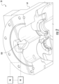
- the screw compressor 20 includes a housing assembly 32 containing a motor 34 and two or more intermeshing screw rotors 36, 38 having respective central longitudinal axes A and B.
- the rotor 36 has a male lobed body 40 extending between a first end 42 and a second end 44.
- the male lobed body 40 is enmeshed with a female lobed body 46 of the other rotor 38.
- the female lobed body 46 of the rotor 38 has a first end 48 and a second end 50.
- Each rotor 36, 38 includes shaft portions 52, 54, 56, 58 extending from the first and second ends 42, 44, 48, 50 of the associated male lobed body 40, and female lobed body 46.
- the shaft portions 52 and 56 are mounted to the housing 32 by one or more inlet bearings 60
- the shaft portions 54, 58 are mounted to the housing 32 by one or more outlet bearings 62 for rotation about the associated rotor axis A, B.
- the motor 34 and the shaft portion 52 of the rotor 36 may be coupled so that the motor 34 drives the rotor 36 about axis A.
- the rotor 36 drives the other rotor 38 in an opposite second direction.
- the housing assembly 32 includes a rotor housing 64 having an upstream/inlet end face 66 and a downstream/discharge end face 68 essentially coplanar with the rotor second ends 44, 50.
- the housing assembly 32 further comprises a motor/inlet housing 70 having a compressor inlet/suction port 72 at an upstream end and having a downstream face 74 mounted to the rotor housing upstream face 66 (e.g., by bolts through both housing pieces).
- the assembly 32 further includes an outlet/discharge housing 76 having an upstream face 78 mounted to the rotor housing downstream face 68 and having an outlet/discharge port 80.
- the rotor housing 64, the motor/inlet housing 70, and outlet housing 76 may each be formed as castings subject to further finish machining.
- the refrigerant vapor enters into the inlet or suction port 72 with a suction pressure and exits the discharge port 80 of the compressor 20 with a discharge pressure.
- the refrigerant vapor within the compression mechanism of the two or more rotors 36, 38, between the inlet port 72 and the discharge port 80 has an intermediate pressure.
- a volume index valve 100 is positioned within the rotor housing 64, adjacent to the discharge end 44, 50 of the rotors 36, 38.
- the volume index valve provides a flow path for vapor from an intermediate point of the rotors 36, 38 to the discharge port 80, bypassing the last portion of the compression.
- the valve 100 moves automatically between a closed position and an open position in response to the operating pressure of the refrigerant vapor within the compressor 20 to control the bypass flow and thus the volume index of the compressor 20.
- the valve 100 is controlled by an actuator.
- the actuator is a solenoid actuator. Proper operation of the volume index valve 100 enables increased efficiency of the compressor 20 by actively controlling the fluid flow therethrough. This is particularly beneficial when the compressor is operated at part load, for example.
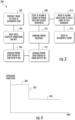
- a flow diagram illustrates a method 200 and system of monitoring operation of the volume index valve in the form of a diagnostic routine. Failure to ensure that the volume index valve 20 is opening and closing properly results in compressor operation at an efficiency that is lower than otherwise available with proper valve operation.
- the method and system advantageously provide verification that the volume index valve is opening and closing in a desired manner.
- Automatic initiation 202 of the method is provided and based on a periodic timer to cause the method to be performed at a specified time interval.
- the method includes waiting for normal and stable operation conditions of the compressor to be met 204 and/or stable operation conditions of the system that the compressor operates within. This may include ensuring that one or more operating modes are present and that stability has been satisfied for a specified period of time. For example, compressor temperature and/or pressure within a specified range over a minimum time period may be required to perform the method.
- stable operating conditions of the system that the compressor operates within an example of a system that the compressor operates within is an air conditioning application. In such embodiments, a refrigerant flow rate, system pressure, system temperature, and system efficiency are examples of operating conditions that may be required to be within a specified range to perform the method. If the stability conditions are not met, the method is aborted.
- detection and recordation of an operating condition of the compressor is made 206 with the volume index valve in a first state that corresponds to a first position.
- a plurality of recordings are made over a given time interval with the volume index valve in the first position, with the recordings averaged to provide a single operating condition reading, referred to herein as a first reading.
- the first reading may be determined by analysis, trending, filtering, etc. The preceding list is merely illustrative and is not intended to be limiting of analysis techniques that may be employed to determine the first reading.
- the first state of the volume index valve corresponds to an energized (i.e., ON) state that provides a closed position of the volume index valve.
- the volume index valve is switched with a controller 99 ( FIG. 2 ) that is in operative communication with the volume index valve to a second state that corresponds to a second position.
- a controller 99 FIG. 2
- the recordings are averaged to provide a single compressor operating condition reading, referred to herein as a second reading.
- the second state of the volume index valve corresponds to a non-energized (i.e., OFF) state that provides an open position of the volume index valve.
- the operating condition of the compressor described above refers to a power reading in some embodiments.
- a variable frequency drive power reading of the compressor is taken at the two above-described states/positions of the volume index valve.
- the operating current of the compressor may be utilized as the operating condition readings.
- the readings are obtained with a processor 98 that is in operative communication with the volume index valve 20 and the compressor 20 generally ( FIG. 2 ).
- the processor 98 may be part of the controller 99 or a separate module.
- the first and second readings are processed by the processor 98 and a difference between the two readings is calculated.
- a first operating condition reading 300 is detected.
- a step-like falloff of the operating condition is observed in certain areas of the compressor map when the volume index valve is switched to the second state/position, as represented with numeral 302.
- the compressor could be either a fixed or variable speed compressor. Due to the availability of power reading in the variable frequency drive, that can be used to perform the volume index valve operational determination. Otherwise, the current reading may be employed for the determination for both variable and fixed speed compressors.
- a second operating condition reading 304 is detected.
- the method includes utilizing the processor 98 to determine the difference between the operating condition readings and to compare that difference to a predetermined threshold stored in memory of the processor 210.
- a correctly operating system will produce a measurable difference that exceeds the predetermined threshold.
- the operating condition measured is power in some embodiments. If the measured power difference fails to exceed the predetermined threshold, this is indicative of a hardware problem with the volume index valve itself and that it is not opening and closing properly. In the case of current as the measured operating condition, a failure to exceed the predetermined threshold is indicative of an electrical failure of the volume index valve. Additionally, installation or mechanical failure may lead to a failure to exceed the predetermined threshold.
- the method includes initiating an alert 212 that prompts an operator to take a corrective action.
- an alert 212 that prompts an operator to take a corrective action.
- a failure of the volume index valve impacts efficiency, but does not warrant a complete shutdown of the compressor so the system continues to operate while the alert is on 214.
- the alert is maintained until it is manually reset, thereby ensuring that an operator has addressed the problem.
- a timer may be reset 216 to determine when the diagnostic routine is again initiated.
- the method and system described herein provides a form of failure detection of the volume index valve.
- the volume index valve is primarily responsible for providing efficiency benefits. Therefore, a failed valve would reduce unit efficiency. Without the method and system described herein, a volume index valve failure could go unnoticed and impair operating efficiency.
Landscapes
- Engineering & Computer Science (AREA)
- Mechanical Engineering (AREA)
- General Engineering & Computer Science (AREA)
- Business, Economics & Management (AREA)
- Emergency Management (AREA)
- Physics & Mathematics (AREA)
- General Physics & Mathematics (AREA)
- Applications Or Details Of Rotary Compressors (AREA)
- Control Of Positive-Displacement Pumps (AREA)
Claims (13)
- Verfahren (200) zur Überwachung eines Volumenindexventils (100) eines Schraubenkompressors, umfassend:Aufzeichnen (206) eines ersten Messwerts (300) eines Betriebszustands des Schraubenkompressors, wenn sich das Volumenindexventil in einem ersten Zustand befindet, der einer ersten Position entspricht;Schalten des Volumenindexventils in einen zweiten Zustand, der einer zweiten Position entspricht;Aufzeichnen (208) eines zweiten Messwerts (304) des Betriebszustands des Schraubenkompressors, wenn sich das Volumenindexventil in dem zweiten Zustand befindet;Berechnen einer Differenz zwischen dem ersten Messwert und dem zweiten Messwert; undVergleichen (210) der Differenz mit einer vorbestimmten Schwellendifferenz, um zu bestimmen, ob sich das Volumenindexventil in einer gewünschten Weise zwischen der ersten Position und der zweiten Position bewegt;wobei das Verfahren ferner Folgendes umfasst:Überprüfen, ob das Volumenindexventil in der gewünschten Weise öffnet und schließt, wenn die Differenz den vorbestimmten Schwellenwert überschreitet;Bestimmen, dass das Volumenindexventil ausgefallen ist und nicht in der gewünschten Weise öffnet und schließt, derart, dass es die Betriebseffizienz beeinträchtigt, wenn die Differenz den vorbestimmten Schwellenwert nicht überschreitet;wobei das Verfahren automatisch basierend auf einem periodischen Zeitgeber initiiert wird, um zu bewirken, dass das Verfahren in einem definierten Zeitintervall durchgeführt wird,wobei bei Initiierung des Verfahrens das Verfahren Warten auf das Erfüllen von stabilen Betriebszuständen (204) des Schraubenkompressors und/oder auf stabile Betriebszustände des Systems, in dem der Schraubenkompressor arbeitet, umfasst.
- Verfahren nach Anspruch 1, ferner umfassend:Aufzeichnen einer ersten Vielzahl von Messwerten des Betriebszustands, wenn sich das Volumenindexventil in der ersten Position befindet;Mitteln der ersten Vielzahl von Messwerten;Aufzeichnen einer zweiten Vielzahl von Messwerten des Betriebszustands, wenn sich das Volumenindexventil in der zweiten Position befindet; undMitteln der zweiten Vielzahl von Messwerten, wobei die berechnete Differenz eine Differenz zwischen der gemittelten ersten und zweiten Vielzahl von Messwerten ist.
- Verfahren nach Anspruch 1 oder 2, ferner umfassend Initiieren einer Warnung, wenn die Differenz den vorbestimmten Schwellenwert nicht überschreitet.
- Verfahren nach Anspruch 3, ferner umfassend Aufrechterhalten der Warnung, bis die Warnung manuell zurückgesetzt wird.
- Verfahren nach Anspruch 3 oder 4, wobei der Schraubenkompressor weiterhin arbeitet, wenn die Warnung initiiert wird.
- Verfahren nach einem der vorhergehenden Ansprüche, wobei der Betriebszustand eine Antriebsleistung variabler Frequenz des Schraubenkompressors (20) ist.
- Verfahren nach einem der Ansprüche 1-5, wobei der Betriebszustand ein gemessener Strom des Schraubenkompressors (20) ist.
- Verfahren nach einem der vorhergehenden Ansprüche, wobei die erste Position des Volumenindexventils (100) eine geöffnete Position ist und die zweite Position des Volumenindexventils eine geschlossene Position ist.
- Verfahren nach einem der Ansprüche 1-7, wobei die erste Position des Volumenindexventils (100) eine geschlossene Position ist und die zweite Position des Volumenindexventils eine geöffnete Position ist.
- System, umfassend:einen Schraubenkompressor;ein Volumenindexventil (100), das in dem Schraubenkompressor angeordnet ist, wobei das Volumenindexventil zwischen einer geöffneten Position und einer geschlossenen Position bewegbar ist; undein Volumenindexventil-Diagnosesystem, umfassend:eine Steuerung (99), die mit dem Volumenindexventil in Wirkverbindung steht, um zu steuern, ob sich das Volumenindexventil in der geöffneten Position oder der geschlossenen Position befindet; undeine Verarbeitungsvorrichtung (98) zum Empfangen von Daten für einen Betriebszustand des Schraubenkompressors, wenn sich das Volumenindexventil in der geöffneten Position befindet und wenn sich das Volumenindexventil in der geschlossenen Position befindet, wobei die Verarbeitungsvorrichtung einen vorbestimmten Schwellenwert einer Differenz zwischen dem Betriebszustand in der geöffneten Position und der geschlossenen Position gespeichert hat,wobei das Volumenindexventil-Diagnosesystem dazu konfiguriert ist, die folgenden Schritte basierend auf einem periodischen Zeitgeber durchzuführen, um zu bewirken, dass die folgenden Schritte in einem vorgegebenen Zeitintervall durchgeführt werden:
Warten auf das Erfüllen von stabilen Betriebszuständen (204) des Schraubenkompressors und/oder auf stabile Betriebszustände des Systems, in dem der Schraubenkompressor arbeitet, bevor die Erfassung der Daten initiiert wird:Bestimmen einer Differenz zwischen dem Betriebszustand in der geöffneten Position und der geschlossenen Position; undVergleichen (210) der Differenz mit einer vorbestimmten Schwellendifferenz, um zu bestimmen, ob sich das Volumenindexventil in einer gewünschten Weise zwischen der geöffneten Position und der geschlossenen Position bewegt;derart, dass das Volumenindexventil-Diagnosesystem dazu konfiguriert ist, zu überprüfen, dass das Volumenindexventil in der gewünschten Weise öffnet und schließt, wenn die Differenz den vorbestimmten Schwellenwert überschreitet;Bestimmen, dass das Volumenindexventil ausgefallen ist und nicht in der gewünschten Weise öffnet und schließt, derart, dass es die Betriebseffizienz beeinträchtigt, wenn die Differenz den vorbestimmten Schwellenwert nicht überschreitet. - System nach Anspruch 10, wobei der Betriebszustand eine Antriebsleistung variabler Frequenz des Kompressors (20) ist.
- System nach Anspruch 10, wobei der Betriebszustand ein gemessener Strom des Kompressors (20) ist.
- System nach einem der Ansprüche 10-12, wobei die Verarbeitungsvorrichtung zu Folgendem programmiert ist:
Initiieren einer Warnung, wenn die Differenz kleiner als der vorbestimmte Schwellenwert ist.
Priority Applications (1)
| Application Number | Priority Date | Filing Date | Title |
|---|---|---|---|
| EP24208995.1A EP4481201A3 (de) | 2016-08-02 | 2017-08-01 | Verfahren zur überwachung eines volumenindexventils eines kompressors und diagnosesystem |
Applications Claiming Priority (2)
| Application Number | Priority Date | Filing Date | Title |
|---|---|---|---|
| US201662369816P | 2016-08-02 | 2016-08-02 | |
| PCT/US2017/044859 WO2018026791A1 (en) | 2016-08-02 | 2017-08-01 | Method of monitoring a volume index valve of a compressor and diagnostic system |
Related Child Applications (2)
| Application Number | Title | Priority Date | Filing Date |
|---|---|---|---|
| EP24208995.1A Division EP4481201A3 (de) | 2016-08-02 | 2017-08-01 | Verfahren zur überwachung eines volumenindexventils eines kompressors und diagnosesystem |
| EP24208995.1A Division-Into EP4481201A3 (de) | 2016-08-02 | 2017-08-01 | Verfahren zur überwachung eines volumenindexventils eines kompressors und diagnosesystem |
Publications (2)
| Publication Number | Publication Date |
|---|---|
| EP3494307A1 EP3494307A1 (de) | 2019-06-12 |
| EP3494307B1 true EP3494307B1 (de) | 2024-12-04 |
Family
ID=59626684
Family Applications (2)
| Application Number | Title | Priority Date | Filing Date |
|---|---|---|---|
| EP24208995.1A Pending EP4481201A3 (de) | 2016-08-02 | 2017-08-01 | Verfahren zur überwachung eines volumenindexventils eines kompressors und diagnosesystem |
| EP17752221.6A Active EP3494307B1 (de) | 2016-08-02 | 2017-08-01 | Verfahren zur überwachung eines volumenindexventils eines kompressors und diagnosesystems |
Family Applications Before (1)
| Application Number | Title | Priority Date | Filing Date |
|---|---|---|---|
| EP24208995.1A Pending EP4481201A3 (de) | 2016-08-02 | 2017-08-01 | Verfahren zur überwachung eines volumenindexventils eines kompressors und diagnosesystem |
Country Status (5)
| Country | Link |
|---|---|
| US (1) | US11460024B2 (de) |
| EP (2) | EP4481201A3 (de) |
| CN (1) | CN109642578B (de) |
| RU (1) | RU2019104011A (de) |
| WO (1) | WO2018026791A1 (de) |
Families Citing this family (2)
| Publication number | Priority date | Publication date | Assignee | Title |
|---|---|---|---|---|
| EP4481201A3 (de) * | 2016-08-02 | 2025-02-26 | Carrier Corporation | Verfahren zur überwachung eines volumenindexventils eines kompressors und diagnosesystem |
| CN109356854B (zh) * | 2018-10-19 | 2019-12-27 | 珠海格力电器股份有限公司 | 变容压缩机运行模式判断方法、设备、变容压缩机及空调 |
Family Cites Families (32)
| Publication number | Priority date | Publication date | Assignee | Title |
|---|---|---|---|---|
| US3811021A (en) * | 1971-12-30 | 1974-05-14 | Tokai Rika Co Ltd | Automatic reset hydraulic switch |
| US4080110A (en) * | 1976-05-10 | 1978-03-21 | Vilter Manufacturing Corporation | Control system for variable capacity gas compressor |
| US5027608A (en) * | 1990-04-20 | 1991-07-02 | American Standard Inc. | Method and apparatus for determining full load condition in a screw compressor |
| US5362206A (en) * | 1993-07-21 | 1994-11-08 | Automation Associates | Pump control responsive to voltage-current phase angle |
| US5524484A (en) | 1993-12-22 | 1996-06-11 | Westinghouse Electric Corporation | Solenoid operated valve diagnostic system |
| US5784245A (en) | 1996-11-27 | 1998-07-21 | Motorola Inc. | Solenoid driver and method for determining solenoid operational status |
| JP3673375B2 (ja) | 1997-09-10 | 2005-07-20 | 株式会社神戸製鋼所 | 容量調節用スライド弁付きスクリュ圧縮機 |
| US6307376B1 (en) | 1998-12-23 | 2001-10-23 | Eaton Corporation | Fault detection system and method for solenoid controlled actuators of a transmission system |
| IT1318802B1 (it) | 2000-08-31 | 2003-09-10 | Nuovo Pignone Spa | Sistema di diagnosi remota dello stato di usura delle valvole diaspirazione e mandata di compressori alternativi. |
| WO2002060606A2 (en) * | 2000-10-23 | 2002-08-08 | James Tyson | Improved sound-based vessel cleaner inspection |
| US6659729B2 (en) * | 2001-02-15 | 2003-12-09 | Mayekawa Mfg. Co., Ltd. | Screw compressor equipment for accommodating low compression ratio and pressure variation and the operation method thereof |
| US6621269B2 (en) | 2001-04-11 | 2003-09-16 | Daimlerchrysler Corporation | System for monitoring solenoid flyback voltage spike |
| JP4123893B2 (ja) * | 2002-10-15 | 2008-07-23 | ダイキン工業株式会社 | スクリュー圧縮機 |
| US6739853B1 (en) * | 2002-12-05 | 2004-05-25 | Carrier Corporation | Compact control mechanism for axial motion control valves in helical screw compressors |
| US7206715B2 (en) * | 2003-12-31 | 2007-04-17 | Cardinal Health 303, Inc. | Empty container detection using container side pressure sensing |
| JP4492320B2 (ja) | 2004-11-30 | 2010-06-30 | トヨタ自動車株式会社 | 異常検出装置 |
| JP4483770B2 (ja) | 2005-11-18 | 2010-06-16 | 株式会社デンソー | 電磁弁異常診断方法 |
| US7357019B2 (en) | 2005-11-30 | 2008-04-15 | Gm Global Technology Operations, Inc. | Faulty lifter oil manifold assembly solenoid diagnostic system |
| CN100543483C (zh) | 2006-07-05 | 2009-09-23 | 鸿富锦精密工业(深圳)有限公司 | 螺线管测试装置 |
| US7441451B2 (en) | 2007-01-31 | 2008-10-28 | Gm Global Technology Operations, Inc. | Diagnostic methods and systems for active fuel management systems |
| US7908913B2 (en) | 2008-12-18 | 2011-03-22 | GM Global Technology Operations LLC | Solenoid diagnostic systems for cylinder deactivation control |
| EP3165770B1 (de) * | 2009-03-26 | 2024-10-23 | Johnson Controls Tyco IP Holdings LLP | Verdichter |
| US8453674B2 (en) * | 2010-03-12 | 2013-06-04 | Target Rock Division Of Curtiss-Wright Flow Control Corporation | Valve fault indication and control |
| JP5734438B2 (ja) * | 2010-09-14 | 2015-06-17 | ジョンソン コントロールズ テクノロジー カンパニーJohnson Controls Technology Company | 容積比制御システムおよび方法 |
| US9032750B2 (en) * | 2011-10-18 | 2015-05-19 | Johnson Controls Technology Company | Manual Vi adjustment mechanism for screw compressors |
| EP2597405A1 (de) | 2011-11-25 | 2013-05-29 | Thermo King Container-Denmark A/S | Automatisches Verfahren zur Pre-Trip-Inspektion eines Behälters mit Klimatisierungsregelungssystem |
| US10533556B2 (en) * | 2013-10-01 | 2020-01-14 | Trane International Inc. | Rotary compressors with variable speed and volume control |
| US10954943B2 (en) * | 2013-12-19 | 2021-03-23 | Carrier Corporation | Compressor comprising a variable volume index valve |
| US9989943B2 (en) * | 2014-04-11 | 2018-06-05 | Trane International Inc. | HVAC systems and controls |
| CN204099200U (zh) * | 2014-09-23 | 2015-01-14 | 江森自控空调冷冻设备(无锡)有限公司 | 可调内容积比的螺杆压缩机 |
| US10677246B2 (en) * | 2016-07-18 | 2020-06-09 | Johnson Controls Technology Company | Variable volume ratio compressor |
| EP4481201A3 (de) * | 2016-08-02 | 2025-02-26 | Carrier Corporation | Verfahren zur überwachung eines volumenindexventils eines kompressors und diagnosesystem |
-
2017
- 2017-08-01 EP EP24208995.1A patent/EP4481201A3/de active Pending
- 2017-08-01 WO PCT/US2017/044859 patent/WO2018026791A1/en not_active Ceased
- 2017-08-01 EP EP17752221.6A patent/EP3494307B1/de active Active
- 2017-08-01 RU RU2019104011A patent/RU2019104011A/ru not_active Application Discontinuation
- 2017-08-01 CN CN201780050187.8A patent/CN109642578B/zh active Active
- 2017-08-01 US US16/322,768 patent/US11460024B2/en active Active
Also Published As
| Publication number | Publication date |
|---|---|
| WO2018026791A1 (en) | 2018-02-08 |
| EP4481201A2 (de) | 2024-12-25 |
| US11460024B2 (en) | 2022-10-04 |
| CN109642578B (zh) | 2022-04-01 |
| EP4481201A3 (de) | 2025-02-26 |
| EP3494307A1 (de) | 2019-06-12 |
| RU2019104011A (ru) | 2020-09-04 |
| US20210381505A1 (en) | 2021-12-09 |
| CN109642578A (zh) | 2019-04-16 |
Similar Documents
| Publication | Publication Date | Title |
|---|---|---|
| EP2992275B1 (de) | System mit einem ersten und einem zweiten verdichter | |
| US11280530B2 (en) | Air conditioner provided with means for predicting and detecting failure in compressor and method for predicting and detecting the failure | |
| CN108431522B (zh) | 带液体喷射的离心压缩机 | |
| KR100834203B1 (ko) | 압축기, 냉매 사이클 및 압축기 제어 방법 | |
| WO2006113780A2 (en) | Modulating proportioning reversing valve | |
| CN108431521B (zh) | 带热气喷射的离心压缩机 | |
| JPWO2007083794A1 (ja) | 空気調和装置 | |
| US8979509B2 (en) | Screw compressor having reverse rotation protection | |
| US20090311119A1 (en) | Screw Compressor Capacity Control | |
| EP3494307B1 (de) | Verfahren zur überwachung eines volumenindexventils eines kompressors und diagnosesystems | |
| KR20070086387A (ko) | 압축기 내의 무동력 역회전 방지 방법 | |
| US10006681B2 (en) | Pulse width modulation with discharge to suction bypass | |
| US11397034B2 (en) | Unloading system for variable speed compressor | |
| JP2007078348A (ja) | 空気調和機 | |
| JPH05157095A (ja) | 遠心圧縮機の容量制御装置 | |
| CN110100137B (zh) | 涡旋卸载检测系统 | |
| JP2025098490A (ja) | スクリュー圧縮機及び冷凍サイクル装置 | |
| WO2018146805A1 (ja) | 冷凍装置 | |
| JP2701634B2 (ja) | 冷凍装置 | |
| JPS591357B2 (ja) | 冷凍サイクル | |
| HK1138351B (en) | Pulse width modulation with discharge to suction bypass | |
| HK1115620B (en) | Prevention of unpowered reverse rotation in compressors | |
| HK1110378B (en) | Compressor, refrigerant cycle and method of controlling a compressor | |
| HK1122859A1 (en) | Compressor lubrication | |
| HK1122859B (en) | Compressor lubrication |
Legal Events
| Date | Code | Title | Description |
|---|---|---|---|
| STAA | Information on the status of an ep patent application or granted ep patent |
Free format text: STATUS: UNKNOWN |
|
| STAA | Information on the status of an ep patent application or granted ep patent |
Free format text: STATUS: THE INTERNATIONAL PUBLICATION HAS BEEN MADE |
|
| PUAI | Public reference made under article 153(3) epc to a published international application that has entered the european phase |
Free format text: ORIGINAL CODE: 0009012 |
|
| STAA | Information on the status of an ep patent application or granted ep patent |
Free format text: STATUS: REQUEST FOR EXAMINATION WAS MADE |
|
| 17P | Request for examination filed |
Effective date: 20190228 |
|
| AK | Designated contracting states |
Kind code of ref document: A1 Designated state(s): AL AT BE BG CH CY CZ DE DK EE ES FI FR GB GR HR HU IE IS IT LI LT LU LV MC MK MT NL NO PL PT RO RS SE SI SK SM TR |
|
| AX | Request for extension of the european patent |
Extension state: BA ME |
|
| DAV | Request for validation of the european patent (deleted) | ||
| DAX | Request for extension of the european patent (deleted) | ||
| STAA | Information on the status of an ep patent application or granted ep patent |
Free format text: STATUS: EXAMINATION IS IN PROGRESS |
|
| 17Q | First examination report despatched |
Effective date: 20211011 |
|
| 17Q | First examination report despatched |
Effective date: 20211021 |
|
| P01 | Opt-out of the competence of the unified patent court (upc) registered |
Effective date: 20230527 |
|
| GRAP | Despatch of communication of intention to grant a patent |
Free format text: ORIGINAL CODE: EPIDOSNIGR1 |
|
| STAA | Information on the status of an ep patent application or granted ep patent |
Free format text: STATUS: GRANT OF PATENT IS INTENDED |
|
| INTG | Intention to grant announced |
Effective date: 20240404 |
|
| RAP3 | Party data changed (applicant data changed or rights of an application transferred) |
Owner name: CARRIER CORPORATION |
|
| GRAS | Grant fee paid |
Free format text: ORIGINAL CODE: EPIDOSNIGR3 |
|
| GRAA | (expected) grant |
Free format text: ORIGINAL CODE: 0009210 |
|
| STAA | Information on the status of an ep patent application or granted ep patent |
Free format text: STATUS: THE PATENT HAS BEEN GRANTED |
|
| AK | Designated contracting states |
Kind code of ref document: B1 Designated state(s): AL AT BE BG CH CY CZ DE DK EE ES FI FR GB GR HR HU IE IS IT LI LT LU LV MC MK MT NL NO PL PT RO RS SE SI SK SM TR |
|
| REG | Reference to a national code |
Ref country code: GB Ref legal event code: FG4D |
|
| REG | Reference to a national code |
Ref country code: CH Ref legal event code: EP |
|
| REG | Reference to a national code |
Ref country code: DE Ref legal event code: R096 Ref document number: 602017086542 Country of ref document: DE |
|
| REG | Reference to a national code |
Ref country code: IE Ref legal event code: FG4D |
|
| REG | Reference to a national code |
Ref country code: LT Ref legal event code: MG9D |
|
| REG | Reference to a national code |
Ref country code: NL Ref legal event code: MP Effective date: 20241204 |
|
| PG25 | Lapsed in a contracting state [announced via postgrant information from national office to epo] |
Ref country code: HR Free format text: LAPSE BECAUSE OF FAILURE TO SUBMIT A TRANSLATION OF THE DESCRIPTION OR TO PAY THE FEE WITHIN THE PRESCRIBED TIME-LIMIT Effective date: 20241204 |
|
| PG25 | Lapsed in a contracting state [announced via postgrant information from national office to epo] |
Ref country code: FI Free format text: LAPSE BECAUSE OF FAILURE TO SUBMIT A TRANSLATION OF THE DESCRIPTION OR TO PAY THE FEE WITHIN THE PRESCRIBED TIME-LIMIT Effective date: 20241204 |
|
| PG25 | Lapsed in a contracting state [announced via postgrant information from national office to epo] |
Ref country code: BG Free format text: LAPSE BECAUSE OF FAILURE TO SUBMIT A TRANSLATION OF THE DESCRIPTION OR TO PAY THE FEE WITHIN THE PRESCRIBED TIME-LIMIT Effective date: 20241204 |
|
| PG25 | Lapsed in a contracting state [announced via postgrant information from national office to epo] |
Ref country code: ES Free format text: LAPSE BECAUSE OF FAILURE TO SUBMIT A TRANSLATION OF THE DESCRIPTION OR TO PAY THE FEE WITHIN THE PRESCRIBED TIME-LIMIT Effective date: 20241204 |
|
| PG25 | Lapsed in a contracting state [announced via postgrant information from national office to epo] |
Ref country code: NO Free format text: LAPSE BECAUSE OF FAILURE TO SUBMIT A TRANSLATION OF THE DESCRIPTION OR TO PAY THE FEE WITHIN THE PRESCRIBED TIME-LIMIT Effective date: 20250304 |
|
| PG25 | Lapsed in a contracting state [announced via postgrant information from national office to epo] |
Ref country code: LV Free format text: LAPSE BECAUSE OF FAILURE TO SUBMIT A TRANSLATION OF THE DESCRIPTION OR TO PAY THE FEE WITHIN THE PRESCRIBED TIME-LIMIT Effective date: 20241204 Ref country code: GR Free format text: LAPSE BECAUSE OF FAILURE TO SUBMIT A TRANSLATION OF THE DESCRIPTION OR TO PAY THE FEE WITHIN THE PRESCRIBED TIME-LIMIT Effective date: 20250305 |
|
| PG25 | Lapsed in a contracting state [announced via postgrant information from national office to epo] |
Ref country code: RS Free format text: LAPSE BECAUSE OF FAILURE TO SUBMIT A TRANSLATION OF THE DESCRIPTION OR TO PAY THE FEE WITHIN THE PRESCRIBED TIME-LIMIT Effective date: 20250304 |
|
| PG25 | Lapsed in a contracting state [announced via postgrant information from national office to epo] |
Ref country code: NL Free format text: LAPSE BECAUSE OF FAILURE TO SUBMIT A TRANSLATION OF THE DESCRIPTION OR TO PAY THE FEE WITHIN THE PRESCRIBED TIME-LIMIT Effective date: 20241204 |
|
| REG | Reference to a national code |
Ref country code: AT Ref legal event code: MK05 Ref document number: 1748433 Country of ref document: AT Kind code of ref document: T Effective date: 20241204 |
|
| PG25 | Lapsed in a contracting state [announced via postgrant information from national office to epo] |
Ref country code: SM Free format text: LAPSE BECAUSE OF FAILURE TO SUBMIT A TRANSLATION OF THE DESCRIPTION OR TO PAY THE FEE WITHIN THE PRESCRIBED TIME-LIMIT Effective date: 20241204 |
|
| PG25 | Lapsed in a contracting state [announced via postgrant information from national office to epo] |
Ref country code: PL Free format text: LAPSE BECAUSE OF FAILURE TO SUBMIT A TRANSLATION OF THE DESCRIPTION OR TO PAY THE FEE WITHIN THE PRESCRIBED TIME-LIMIT Effective date: 20241204 |
|
| PG25 | Lapsed in a contracting state [announced via postgrant information from national office to epo] |
Ref country code: IS Free format text: LAPSE BECAUSE OF FAILURE TO SUBMIT A TRANSLATION OF THE DESCRIPTION OR TO PAY THE FEE WITHIN THE PRESCRIBED TIME-LIMIT Effective date: 20250404 |
|
| PG25 | Lapsed in a contracting state [announced via postgrant information from national office to epo] |
Ref country code: PT Free format text: LAPSE BECAUSE OF FAILURE TO SUBMIT A TRANSLATION OF THE DESCRIPTION OR TO PAY THE FEE WITHIN THE PRESCRIBED TIME-LIMIT Effective date: 20250404 |
|
| PG25 | Lapsed in a contracting state [announced via postgrant information from national office to epo] |
Ref country code: EE Free format text: LAPSE BECAUSE OF FAILURE TO SUBMIT A TRANSLATION OF THE DESCRIPTION OR TO PAY THE FEE WITHIN THE PRESCRIBED TIME-LIMIT Effective date: 20241204 |
|
| PG25 | Lapsed in a contracting state [announced via postgrant information from national office to epo] |
Ref country code: AT Free format text: LAPSE BECAUSE OF FAILURE TO SUBMIT A TRANSLATION OF THE DESCRIPTION OR TO PAY THE FEE WITHIN THE PRESCRIBED TIME-LIMIT Effective date: 20241204 Ref country code: RO Free format text: LAPSE BECAUSE OF FAILURE TO SUBMIT A TRANSLATION OF THE DESCRIPTION OR TO PAY THE FEE WITHIN THE PRESCRIBED TIME-LIMIT Effective date: 20241204 |
|
| PG25 | Lapsed in a contracting state [announced via postgrant information from national office to epo] |
Ref country code: SK Free format text: LAPSE BECAUSE OF FAILURE TO SUBMIT A TRANSLATION OF THE DESCRIPTION OR TO PAY THE FEE WITHIN THE PRESCRIBED TIME-LIMIT Effective date: 20241204 |
|
| PG25 | Lapsed in a contracting state [announced via postgrant information from national office to epo] |
Ref country code: CZ Free format text: LAPSE BECAUSE OF FAILURE TO SUBMIT A TRANSLATION OF THE DESCRIPTION OR TO PAY THE FEE WITHIN THE PRESCRIBED TIME-LIMIT Effective date: 20241204 |
|
| PG25 | Lapsed in a contracting state [announced via postgrant information from national office to epo] |
Ref country code: IT Free format text: LAPSE BECAUSE OF FAILURE TO SUBMIT A TRANSLATION OF THE DESCRIPTION OR TO PAY THE FEE WITHIN THE PRESCRIBED TIME-LIMIT Effective date: 20241204 |
|
| REG | Reference to a national code |
Ref country code: DE Ref legal event code: R097 Ref document number: 602017086542 Country of ref document: DE |
|
| PG25 | Lapsed in a contracting state [announced via postgrant information from national office to epo] |
Ref country code: SE Free format text: LAPSE BECAUSE OF FAILURE TO SUBMIT A TRANSLATION OF THE DESCRIPTION OR TO PAY THE FEE WITHIN THE PRESCRIBED TIME-LIMIT Effective date: 20241204 |
|
| PG25 | Lapsed in a contracting state [announced via postgrant information from national office to epo] |
Ref country code: DK Free format text: LAPSE BECAUSE OF FAILURE TO SUBMIT A TRANSLATION OF THE DESCRIPTION OR TO PAY THE FEE WITHIN THE PRESCRIBED TIME-LIMIT Effective date: 20241204 |
|
| PGFP | Annual fee paid to national office [announced via postgrant information from national office to epo] |
Ref country code: DE Payment date: 20250724 Year of fee payment: 9 |
|
| PLBE | No opposition filed within time limit |
Free format text: ORIGINAL CODE: 0009261 |
|
| STAA | Information on the status of an ep patent application or granted ep patent |
Free format text: STATUS: NO OPPOSITION FILED WITHIN TIME LIMIT |
|
| PGFP | Annual fee paid to national office [announced via postgrant information from national office to epo] |
Ref country code: GB Payment date: 20250724 Year of fee payment: 9 |
|
| PGFP | Annual fee paid to national office [announced via postgrant information from national office to epo] |
Ref country code: FR Payment date: 20250723 Year of fee payment: 9 |
|
| 26N | No opposition filed |
Effective date: 20250905 |