EP3490657B1 - Systeme zur bereitstellung einer intravaskulären vorrichtung für den mitralring - Google Patents
Systeme zur bereitstellung einer intravaskulären vorrichtung für den mitralring Download PDFInfo
- Publication number
- EP3490657B1 EP3490657B1 EP17749090.1A EP17749090A EP3490657B1 EP 3490657 B1 EP3490657 B1 EP 3490657B1 EP 17749090 A EP17749090 A EP 17749090A EP 3490657 B1 EP3490657 B1 EP 3490657B1
- Authority
- EP
- European Patent Office
- Prior art keywords
- catheter
- delivery
- outer sheath
- steering
- distal
- Prior art date
- Legal status (The legal status is an assumption and is not a legal conclusion. Google has not performed a legal analysis and makes no representation as to the accuracy of the status listed.)
- Active
Links
Images


Classifications
-
- A—HUMAN NECESSITIES
- A61—MEDICAL OR VETERINARY SCIENCE; HYGIENE
- A61F—FILTERS IMPLANTABLE INTO BLOOD VESSELS; PROSTHESES; DEVICES PROVIDING PATENCY TO, OR PREVENTING COLLAPSING OF, TUBULAR STRUCTURES OF THE BODY, e.g. STENTS; ORTHOPAEDIC, NURSING OR CONTRACEPTIVE DEVICES; FOMENTATION; TREATMENT OR PROTECTION OF EYES OR EARS; BANDAGES, DRESSINGS OR ABSORBENT PADS; FIRST-AID KITS
- A61F2/00—Filters implantable into blood vessels; Prostheses, i.e. artificial substitutes or replacements for parts of the body; Appliances for connecting them with the body; Devices providing patency to, or preventing collapsing of, tubular structures of the body, e.g. stents
- A61F2/02—Prostheses implantable into the body
- A61F2/24—Heart valves ; Vascular valves, e.g. venous valves; Heart implants, e.g. passive devices for improving the function of the native valve or the heart muscle; Transmyocardial revascularisation [TMR] devices; Valves implantable in the body
- A61F2/2427—Devices for manipulating or deploying heart valves during implantation
- A61F2/2439—Expansion controlled by filaments
-
- A—HUMAN NECESSITIES
- A61—MEDICAL OR VETERINARY SCIENCE; HYGIENE
- A61B—DIAGNOSIS; SURGERY; IDENTIFICATION
- A61B17/00—Surgical instruments, devices or methods
- A61B17/04—Surgical instruments, devices or methods for suturing wounds; Holders or packages for needles or suture materials
- A61B17/0469—Suturing instruments for use in minimally invasive surgery, e.g. endoscopic surgery
-
- A—HUMAN NECESSITIES
- A61—MEDICAL OR VETERINARY SCIENCE; HYGIENE
- A61F—FILTERS IMPLANTABLE INTO BLOOD VESSELS; PROSTHESES; DEVICES PROVIDING PATENCY TO, OR PREVENTING COLLAPSING OF, TUBULAR STRUCTURES OF THE BODY, e.g. STENTS; ORTHOPAEDIC, NURSING OR CONTRACEPTIVE DEVICES; FOMENTATION; TREATMENT OR PROTECTION OF EYES OR EARS; BANDAGES, DRESSINGS OR ABSORBENT PADS; FIRST-AID KITS
- A61F2/00—Filters implantable into blood vessels; Prostheses, i.e. artificial substitutes or replacements for parts of the body; Appliances for connecting them with the body; Devices providing patency to, or preventing collapsing of, tubular structures of the body, e.g. stents
- A61F2/02—Prostheses implantable into the body
- A61F2/24—Heart valves ; Vascular valves, e.g. venous valves; Heart implants, e.g. passive devices for improving the function of the native valve or the heart muscle; Transmyocardial revascularisation [TMR] devices; Valves implantable in the body
- A61F2/2427—Devices for manipulating or deploying heart valves during implantation
- A61F2/2436—Deployment by retracting a sheath
-
- A—HUMAN NECESSITIES
- A61—MEDICAL OR VETERINARY SCIENCE; HYGIENE
- A61F—FILTERS IMPLANTABLE INTO BLOOD VESSELS; PROSTHESES; DEVICES PROVIDING PATENCY TO, OR PREVENTING COLLAPSING OF, TUBULAR STRUCTURES OF THE BODY, e.g. STENTS; ORTHOPAEDIC, NURSING OR CONTRACEPTIVE DEVICES; FOMENTATION; TREATMENT OR PROTECTION OF EYES OR EARS; BANDAGES, DRESSINGS OR ABSORBENT PADS; FIRST-AID KITS
- A61F2/00—Filters implantable into blood vessels; Prostheses, i.e. artificial substitutes or replacements for parts of the body; Appliances for connecting them with the body; Devices providing patency to, or preventing collapsing of, tubular structures of the body, e.g. stents
- A61F2/95—Instruments specially adapted for placement or removal of stents or stent-grafts
- A61F2/9517—Instruments specially adapted for placement or removal of stents or stent-grafts handle assemblies therefor
-
- A—HUMAN NECESSITIES
- A61—MEDICAL OR VETERINARY SCIENCE; HYGIENE
- A61M—DEVICES FOR INTRODUCING MEDIA INTO, OR ONTO, THE BODY; DEVICES FOR TRANSDUCING BODY MEDIA OR FOR TAKING MEDIA FROM THE BODY; DEVICES FOR PRODUCING OR ENDING SLEEP OR STUPOR
- A61M25/00—Catheters; Hollow probes
- A61M25/0043—Catheters; Hollow probes characterised by structural features
- A61M25/0045—Catheters; Hollow probes characterised by structural features multi-layered, e.g. coated
-
- A—HUMAN NECESSITIES
- A61—MEDICAL OR VETERINARY SCIENCE; HYGIENE
- A61M—DEVICES FOR INTRODUCING MEDIA INTO, OR ONTO, THE BODY; DEVICES FOR TRANSDUCING BODY MEDIA OR FOR TAKING MEDIA FROM THE BODY; DEVICES FOR PRODUCING OR ENDING SLEEP OR STUPOR
- A61M25/00—Catheters; Hollow probes
- A61M25/0043—Catheters; Hollow probes characterised by structural features
- A61M25/005—Catheters; Hollow probes characterised by structural features with embedded materials for reinforcement, e.g. wires, coils, braids
-
- A—HUMAN NECESSITIES
- A61—MEDICAL OR VETERINARY SCIENCE; HYGIENE
- A61M—DEVICES FOR INTRODUCING MEDIA INTO, OR ONTO, THE BODY; DEVICES FOR TRANSDUCING BODY MEDIA OR FOR TAKING MEDIA FROM THE BODY; DEVICES FOR PRODUCING OR ENDING SLEEP OR STUPOR
- A61M25/00—Catheters; Hollow probes
- A61M25/0043—Catheters; Hollow probes characterised by structural features
- A61M25/0054—Catheters; Hollow probes characterised by structural features with regions for increasing flexibility
-
- A—HUMAN NECESSITIES
- A61—MEDICAL OR VETERINARY SCIENCE; HYGIENE
- A61M—DEVICES FOR INTRODUCING MEDIA INTO, OR ONTO, THE BODY; DEVICES FOR TRANSDUCING BODY MEDIA OR FOR TAKING MEDIA FROM THE BODY; DEVICES FOR PRODUCING OR ENDING SLEEP OR STUPOR
- A61M25/00—Catheters; Hollow probes
- A61M25/01—Introducing, guiding, advancing, emplacing or holding catheters
- A61M25/0105—Steering means as part of the catheter or advancing means; Markers for positioning
- A61M25/0133—Tip steering devices
- A61M25/0136—Handles therefor
-
- A—HUMAN NECESSITIES
- A61—MEDICAL OR VETERINARY SCIENCE; HYGIENE
- A61M—DEVICES FOR INTRODUCING MEDIA INTO, OR ONTO, THE BODY; DEVICES FOR TRANSDUCING BODY MEDIA OR FOR TAKING MEDIA FROM THE BODY; DEVICES FOR PRODUCING OR ENDING SLEEP OR STUPOR
- A61M25/00—Catheters; Hollow probes
- A61M25/01—Introducing, guiding, advancing, emplacing or holding catheters
- A61M25/0105—Steering means as part of the catheter or advancing means; Markers for positioning
- A61M25/0133—Tip steering devices
- A61M25/0138—Tip steering devices having flexible regions as a result of weakened outer material, e.g. slots, slits, cuts, joints or coils
-
- A—HUMAN NECESSITIES
- A61—MEDICAL OR VETERINARY SCIENCE; HYGIENE
- A61M—DEVICES FOR INTRODUCING MEDIA INTO, OR ONTO, THE BODY; DEVICES FOR TRANSDUCING BODY MEDIA OR FOR TAKING MEDIA FROM THE BODY; DEVICES FOR PRODUCING OR ENDING SLEEP OR STUPOR
- A61M25/00—Catheters; Hollow probes
- A61M25/01—Introducing, guiding, advancing, emplacing or holding catheters
- A61M25/0105—Steering means as part of the catheter or advancing means; Markers for positioning
- A61M25/0133—Tip steering devices
- A61M25/0147—Tip steering devices with movable mechanical means, e.g. pull wires
-
- A—HUMAN NECESSITIES
- A61—MEDICAL OR VETERINARY SCIENCE; HYGIENE
- A61M—DEVICES FOR INTRODUCING MEDIA INTO, OR ONTO, THE BODY; DEVICES FOR TRANSDUCING BODY MEDIA OR FOR TAKING MEDIA FROM THE BODY; DEVICES FOR PRODUCING OR ENDING SLEEP OR STUPOR
- A61M25/00—Catheters; Hollow probes
- A61M25/01—Introducing, guiding, advancing, emplacing or holding catheters
- A61M25/09—Guide wires
-
- A—HUMAN NECESSITIES
- A61—MEDICAL OR VETERINARY SCIENCE; HYGIENE
- A61M—DEVICES FOR INTRODUCING MEDIA INTO, OR ONTO, THE BODY; DEVICES FOR TRANSDUCING BODY MEDIA OR FOR TAKING MEDIA FROM THE BODY; DEVICES FOR PRODUCING OR ENDING SLEEP OR STUPOR
- A61M25/00—Catheters; Hollow probes
- A61M2025/0004—Catheters; Hollow probes having two or more concentrically arranged tubes for forming a concentric catheter system
-
- A—HUMAN NECESSITIES
- A61—MEDICAL OR VETERINARY SCIENCE; HYGIENE
- A61M—DEVICES FOR INTRODUCING MEDIA INTO, OR ONTO, THE BODY; DEVICES FOR TRANSDUCING BODY MEDIA OR FOR TAKING MEDIA FROM THE BODY; DEVICES FOR PRODUCING OR ENDING SLEEP OR STUPOR
- A61M25/00—Catheters; Hollow probes
- A61M25/01—Introducing, guiding, advancing, emplacing or holding catheters
- A61M2025/0175—Introducing, guiding, advancing, emplacing or holding catheters having telescopic features, interengaging nestable members movable in relations to one another
-
- A—HUMAN NECESSITIES
- A61—MEDICAL OR VETERINARY SCIENCE; HYGIENE
- A61M—DEVICES FOR INTRODUCING MEDIA INTO, OR ONTO, THE BODY; DEVICES FOR TRANSDUCING BODY MEDIA OR FOR TAKING MEDIA FROM THE BODY; DEVICES FOR PRODUCING OR ENDING SLEEP OR STUPOR
- A61M25/00—Catheters; Hollow probes
- A61M25/0097—Catheters; Hollow probes characterised by the hub
-
- A—HUMAN NECESSITIES
- A61—MEDICAL OR VETERINARY SCIENCE; HYGIENE
- A61M—DEVICES FOR INTRODUCING MEDIA INTO, OR ONTO, THE BODY; DEVICES FOR TRANSDUCING BODY MEDIA OR FOR TAKING MEDIA FROM THE BODY; DEVICES FOR PRODUCING OR ENDING SLEEP OR STUPOR
- A61M25/00—Catheters; Hollow probes
- A61M25/01—Introducing, guiding, advancing, emplacing or holding catheters
- A61M25/06—Body-piercing guide needles or the like
- A61M25/0662—Guide tubes
Definitions
- the present disclosure generally relates to an implantable cardiac device.
- this disclosure describes devices and systems for delivering an intravascular device to targeted anatomy within the heart such as at the mitral annulus.
- Intravascular medical procedures allow the performance of therapeutic treatments in a variety of locations within a patient's body while requiring only relatively small access incisions.
- An intravascular procedure may, for example, eliminate the need for open-heart surgery, reducing risks, costs, and time associated with an open-heart procedure. The intravascular procedure also enables faster recovery times with lower associated costs and risks of complication.
- An example of an intravascular procedure that significantly reduces procedure and recovery time and cost over conventional open surgery is a heart valve replacement or repair procedure in which an artificial valve or valve repair device is guided to the heart through the patient's vasculature. For example, a catheter is inserted into the patient's vasculature and directed to the inferior vena cava.
- the catheter is then urged through the inferior vena cava toward the heart by applying force longitudinally to the catheter.
- the catheter Upon entering the heart from the inferior vena cava, the catheter enters the right atrium.
- the distal end of the catheter may be deflected by one or more deflecting mechanisms, which can be achieved by a tension cable, or other mechanisms positioned inside the catheter. Precise control of the distal end of the catheter allows for more reliable and faster positioning of a medical device and/or implant and other improvements in the procedure.
- An intravascularly delivered device needs to be placed precisely to ensure a correct positioning of the medical device, which is essential for its functionality, as the device may be difficult to reposition after the device is fully deployed from the delivery system. Additionally, the ability to recapture a partially deployed device is desirable in the event that the distal end of the catheter moves relative to the target location and compromises the precise positioning of the device.
- US 7,736,388 B2 there are described devices, systems and methods for tissue approximation and repair at treatment sites.
- the devices, systems and methods are said to find use in a variety of therapeutic procedures, including endovascular, minimally-invasive, and open surgical procedures, and to be capable of use in various anatomical regions, including the abdomen, thorax, cardiovascular system, heart, intestinal tract, stomach, urinary tract, bladder, lung, and other organs, vessels and tissues.
- the described devices, systems and methods are said to be particularly useful in those procedures requiring minimally-invasive or endovascular access to remote tissue locations, where the instruments utilized must negotiate long, narrow, and tortuous pathways to the treatment site.
- many of the described devices and systems are adapted to be reversible and removable from the patient at any point without interference with or trauma to internal tissues.
- prosthetic valves and their component parts, together with prosthetic valve delivery devices and methods for their use.
- the prosthetic valves are said to be particularly adapted for use in percutaneous aortic valve replacement procedures.
- the delivery devices are also said to be particularly adapted for use in minimally invasive surgical procedures.
- the delivery device includes a catheter having a deployment mechanism attached to its distal end, and a handle mechanism attached to its proximal end.
- a plurality of tethers are provided to selectively restrain the valve during deployment.
- a number of mechanisms for active deployment of partially expanded prosthetic valves are also described.
- a steerable catheter sheath for use in directing a catheter into a desired position.
- the sheath includes an elongated member configured to receive the catheter therein.
- the distal end of the elongated member is steerable in two directions, each direction having a different bent configuration, e.g., a sharp curve in one direction and an open arching curve in the other direction.
- a resilient structure having different bending properties in each of its lateral sides is carried in the distal portion of the elongated member and causes the asymmetric bending.
- the resilient structure includes a hypotube with a plurality of notches and slits in the sides.
- the resilient structure is covered in an outer coating having different durometer portions. The sheath is said to be useful for accessing left and right pulmonary veins when a transeptal entry approach is used into the left atrium.
- the present disclosure describes devices and systems for intravascularly delivering an intravascular device to a targeted cardiac valve.
- a delivery system having the features of claim 1 for delivering an implantable intravascular device to a targeted cardiac valve.
- the delivery system for intravascularly delivering an intravascular device to a targeted cardiac valve includes a handle assembly and an elongated delivery member.
- the delivery member has a proximal end and a distal end. The proximal end of the delivery member is coupled to the handle assembly and the delivery member extends distally from the handle assembly to its distal end.
- the delivery member is configured to detachably couple to an implantable intravascular device at its distal end.
- the delivery member also includes an outer sheath having a cover configured to constrain and/or hold the intravascular device in a pre-deployed configuration, a steering component configured to curve the delivery member in a compound curve that enables intravascular delivery of the delivery member to the targeted cardiac valve, a delivery catheter configured to longitudinally translate the intravascular device relative to the outer sheath, and a suture catheter having one or more tethers configured to detachably couple to a proximal section of the intravascular device.
- the suture catheter is longitudinally translatable relative to the delivery catheter to enable adjustment of tension in the one or more tethers.
- the steering component is a steering catheter nested within the outer sheath.
- the steering catheter may include a plurality of tension cables and corresponding tension cable lumen, the tension cables providing for steering of the steering catheter by adjusting tension in the tension cables.
- the steering catheter may be formed as a hypotube, the hypotube having a cut pattern that increases the flexibility of the hypotube relative to an uncut section of hypotube.
- the steering catheter may include a plurality of microfabricated cuts along at least a proximal section of the distal piece, the microfabricated cuts being configured to provide bending in a single plane.
- the outer sheath includes a coil and a braided sleeve.
- the coil of the outer sheath may be formed from a coil wire having a "D" shaped cross section to provide a rounded inner surface.
- the outer sheath may include a fluid impermeable flexible polymer cover disposed over the coil and braided sleeve.
- the distal piece of the outer sheath is rotationally decoupled from the remainder of the outer sheath.
- the delivery catheter includes a compression coil at least at a distal section.
- the delivery system is supported by a fixture.
- the fixture includes a plurality of supports to support the outer sheath, a steering catheter handle, a delivery catheter holder, and a suture catheter holder.
- the fixture also includes one or more adjustable controls which enable movement of different components of the delivery member relative to other components of the delivery member.
- the fixture includes a delivery device adjustor for longitudinally translating the entire delivery device relative to a base, an outer sheath adjustor for translating the outer sheath relative to other components of the delivery member, and a deployment adjustor for translating the delivery catheter, outer sheath, and suture catheter relative to the steering catheter.
- the handle assembly includes a delivery catheter holder, a suture catheter holder, and a suture catheter adjustor, the suture catheter adjustor being coupled to the delivery catheter holder, and the suture catheter holder including threads which engage with corresponding threads of the suture catheter adjustor such that rotation of the suture catheter adjustor translates the suture catheter holder relative to the delivery catheter holder
- the present disclosure is directed to devices and systems for delivering an implantable intravascular device to targeted intravascular anatomy, including a targeted cardiac valve.
- Suitable intravascular devices that may be utilized in conjunction with the delivery system described herein may include valve repair devices, annuloplasty devices, valve clip devices, artificial heart valve devices, and other interventional devices.
- FIG. 1 illustrates an exemplary delivery system 190.
- the delivery system 190 includes a handle assembly 130 and an elongated delivery member 70 (also referred to herein as simply the elongated member or the delivery member).
- the delivery member 70 is coupled to the handle assembly 130 and extends distally from the handle assembly 130.
- the delivery member 70 includes a plurality of catheter and/or hypotube members which provide different functionality during operation of the delivery system 190 to enable effective delivery and deployment of an intravascular device.
- an outer sheath 82 (also referred to herein as delivery sheath 82) is coupled to an end ring 131, and the outer sheath 82 extends to a distal end where it is coupled to a distal piece 84.
- the distal piece 84 functions to house an intravascular device in a compressed, pre-deployed state during intravascular delivery of the device to the targeted cardiac site.
- a steering catheter handle 132 is disposed proximal of the end ring 131.
- the proximal end of a steering catheter 80 is coupled to the steering catheter handle 132, and the steering catheter 80 extends distally from the steering catheter handle 132 into the outer sheath 82.
- the steering catheter handle 132 includes one or more controls 134 which are operatively coupled to the steering catheter so that manipulation of the controls 134 adjusts the curvature of the steering catheter 80. Because the steering catheter 80 is nested within the outer sheath 82, curving of the steering catheter 80 causes corresponding curving/steering in the outer sheath 82.
- the illustrated delivery member 70 includes additional components which are not visible in the view of Figure 1 but may be seen in the cross-sectional view of Figure 2 .
- Figure 2 illustrates a cross-sectional view of the delivery member 70 taken along the cross-section line 2-2.
- the steering catheter 80 is disposed within the outer sheath 82.
- a delivery catheter 78 is disposed within the steering catheter 80.
- a suture catheter 72 is disposed within the delivery catheter 78, and a guidewire tube 86 is disposed within the suture catheter 72.
- the guidewire tube 86 is configured for receiving a guidewire 87. Additional structural details and related functionality of these components will be described in more detail below.
- the particular nested configuration shown in Figure 2 represents one preferred arrangement, alternative arrangements may include a different concentric arrangement of constituent parts. For example, some arrangements may configure the outermost member with steering functionality, some arrangements may include more than one catheter with steering functionality, some arrangements may trade the radial positions of the suture catheter 72 and delivery catheter 78, etcetera.
- the steering catheter 80 includes a plurality of lumens 81 extending through the length of the steering catheter 80.
- the lumens 81 may be configured for receiving tension cables which extend between the controls 134 and the distal end of the steering catheter 80.
- One or more tension cables may additionally or alternatively be coupled to intermediate sections of the steering catheter 80.
- Manipulation of the controls 134 therefore adjusts tension in the tension cables to increase or decrease curvature of the steering catheter 80 at various positions.
- the controls 134 are shown here as knobs, alternative arrangements may additionally or alternatively include one or more buttons, sliders, ratcheting mechanisms, or other suitable controls capable of adjusting tension to provide steering.
- Illustrative structures that can be used as part of the steering catheter handle 132 and or steering catheter 80 are described in U.S. Patent No. 7,736,388 .
- a delivery catheter holder 136 is disposed proximal of the steering catheter handle 132.
- the proximal end of the delivery catheter 78 is coupled to the delivery catheter holder 136.
- the delivery catheter 78 extends distally away from the delivery catheter holder 136 and into the steering catheter 80.
- a suture catheter holder 138 is disposed proximal of the delivery catheter holder 136.
- the suture catheter 72 may be coupled to the suture catheter holder 138 so that translation of the suture catheter holder 138 corresponds to movement of the suture catheter 72.
- the suture catheter 72 may be selectively locked relative to the suture catheter holder 138 through a set screw, clamp, or other selective holding mechanism.
- the suture catheter 72 extends distally away from the suture catheter holder 138 and into the delivery catheter 78.
- An alignment ring 137 and alignment rods 142 provide structural support for maintaining proper alignment of the delivery catheter holder 136 and suture catheter holder 138, which thereby functions to maintain coaxial alignment of the delivery catheter 78 and suture catheter 72.
- a suture catheter control 139 is coupled to the alignment ring 137 and is operatively coupled to the suture catheter holder 138. Manipulation of the suture catheter control 139 adjusts the relative positioning of the delivery catheter holder 136 and suture catheter holder 138. In the illustrated arrangement, the suture catheter control 139 operates through threaded engagement with the suture catheter holder 138, such that rotation of the suture catheter control 139 translates the suture catheter holder 138 relative to the control 139 and therefore relative to the delivery catheter holder 136.
- Alternative arrangements may additionally or alternatively include one or more of a slider and rail assembly, a ratcheting mechanism, or other suitable means of linear adjustment.
- a second set of alignment rods 142 extend proximally from the suture catheter holder 138 to a suture catheter cap 143.
- the suture catheter 72 may extend proximally to, and be attached to, the suture catheter cap 143.
- a user may advance and retract the suture catheter 72 by sliding/translating the suture catheter cap 143 along the alignment rods 142.
- the guidewire tube 86 extends distally through the catheter cap 143 and into the suture catheter 72 at the suture catheter holder 138.
- the guidewire tube 86 extends to the distal end of the delivery member 70 where it is attached to a distal tip 88.
- the distal tip 88 is preferably formed from a flexible polymer material and provides an angled, atraumatic shape which assists in passing the delivery member 70 across the inter-atrial septum to the mitral annulus, which is required in a typical intravascular approach such as a transfemoral approach.
- the guidewire tube 86 is selectively translatable relative to the suture catheter cap 143, so that the guidewire tube 86 and distal tip 88 may be linearly translated relative to the suture catheter 72.
- the guidewire tube 86 is coupled to a guidewire tube handle 140.
- the guidewire tube 86 may be selectively locked in longitudinal position relative to the suture catheter holder 138 and/or suture catheter cap 143, such as through a set screw, clamp, or other selective fastener.
- a fastening structure may be associated with the suture catheter cap 143.
- the guidewire tube 86 When the guidewire tube 86 is linearly locked to the suture catheter cap 143, the guidewire tube 86 will longitudinally translate with the delivery catheter holder 138 and/or suture catheter cap 143. The distal tip 88 and suture catheter 72 will thus move together. When unlocked, the guidewire tube 86 (and likewise the distal tip 88) may be moved relative to the suture catheter 72. As described in more detail below, the ability to retract the distal tip 88 relative to the suture catheter 72 reduces the risk that the distal tip 88 will become overextended during deployment, where it could become tangled in chordae tendineae and/or cause injury to cardiac tissue.
- the illustrated suture catheter holder 138 also includes a set of tensioner posts 144.
- sutures may extend from the distal end of the suture catheter 72 to the tensioner posts 144.
- the sutures may be wrapped around respective tensioner posts 144 such that screwing/unscrewing of the tensioner posts 144 adjusts tension of the coupled sutures.
- sutures do not pass entirely to the proximal handle 130 and the tensioner posts 144 may be omitted.
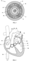
- FIG 3 illustrates a schematic representation of a patient's heart and a delivery procedure that may be conducted using the illustrated delivery system 190.
- the delivery member 70 may be inserted into the patient's vasculature (e.g., through a transfemoral approach) and directed to the inferior vena cava 150.
- the delivery member 70 is passed through the inferior vena cava 150 toward the heart.
- the delivery member 70 Upon entering the heart from the inferior vena cava 150, the delivery member 70 enters the right atrium 152.
- the delivery member 70 must further pass into the left atrium 156 by passing through a puncture in the intra-atrial septum 154.
- the delivery member 70 may be passed through the inferior vena cava 150 and into the right atrium 152, where it may then be positioned and used to perform the procedure related to the tricuspid valve.
- the delivery member 70 may be passed through the inferior vena cava 150 and into the right atrium 152, where it may then be positioned and used to perform the procedure related to the tricuspid valve.
- the examples described herein relate to delivery to the mitral valve, one or more examples may be utilized in other cardiac procedures, including those involving the tricuspid valve.
- transfemoral approach for accessing a targeted cardiac valve is one preferred method, it will be understood that the arrangements described herein may also be utilized where alternative approaches are used.
- arrangements described herein may be utilized in a transjugular approach, transapical approach, or other suitable approach to the targeted anatomy.
- delivery of the replacement valve or other interventional device is preferably carried out from an atrial aspect (i.e., with the distal end of the delivery member 70 positioned within the atrium superior to the targeted valve).
- the illustrated arrangements are shown from such an atrial aspect.
- the interventional device described herein may also be delivered from a ventricular aspect.
- a guidewire 87 is utilized in conjunction with the delivery member 70.
- the guidewire 87 e.g., 0.356mm (0.014 inches) in diameter, 0.457mm (0.018 inches) in diameter, or 0.889mm(0.035 inches) in diameter
- the guidewire 87 may be routed through the guidewire tube 86 of the delivery member 70 to the targeted cardiac valve.
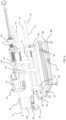
- Figure 4 illustrates the handle assembly 130 positioned on a fixture 176.
- the fixture 176 includes a stabilizer 160 which supports the handle assembly 130 and provides adjustment of various components of the handle assembly 130.
- the fixture 176 also includes a base 161 configured to support the stabilizer 160 and handle assembly 130, and to provide the ability to adjust the position of the entire handle assembly 130.
- the base 161 may include wheels 162 for moving and positioning of the assembly.
- the base 161 also includes an angular adjuster 164 configured for adjusting the angle of the handle assembly 130 by lifting or lowering the upper section of the base 161.
- the base 161 further includes a slider lock 163. Unlocking of the slider lock 163 allows a user to slide an upper section 191 of the base forward or backward relative to a lower section 192 of the base in order to selectively advance or retract the delivery system.
- the fixture 176 may also include a base bearing 165 connected to the base 160 and to a stabilizer adjustor 173.
- the base bearing 165 allows the stabilizer adjustor 173 to rotate but prevents linear movement of the stabilizer adjustor 173 relative to the base bearing 165.
- the stabilizer adjustor 173 includes threads which engage with corresponding threads of a proximal support 171 of the stabilizer 160.
- the proximal support 171 is mechanically connected to a steering catheter handle support 169 and a distal support 172.
- Rotation of the stabilizer adjustor 173, as shown by arrow 178 thus causes the entire stabilizer 160 to translate relative to the base 161. For example, rotation of the stabilizer adjustor 173 in one direction will advance the stabilizer 160 (and handle assembly 130 with it) while rotation in the opposite direction will retract.
- the illustrated fixture 176 is therefore configured to provide dual-mode translation of the delivery system.
- manipulation of the slider lock 168 may be utilized for translational adjustments of the delivery system on a relatively more macro level
- manipulation of the stabilizer adjustor 173 may be utilized for finer translational adjustments on a relatively more micro level.
- the combination of both modes of translation beneficially combines the ability for rapid adjustment across longer translational movements with the ability for fine adjustment where more precise movements are required or preferred.
- the stabilizer 160 includes additional components configured to provide adjustment of the different components of the handle assembly 130.
- the outer sheath 82 is supported by an outer sheath support 166.
- the outer sheath support 166 is disposed upon a slider block 167.
- the outer sheath support 166 can be selectively translated upon the slider block 167 to translate the outer sheath 82 relative to the other components of the delivery member 70.
- a slider lock 168 can lock the position of the outer sheath support 166 upon the slider block 167 to prevent translation via sliding.
- the steering catheter handle 132 is supported by the steering catheter handle support 169, and the delivery catheter holder 136 is supported by a delivery catheter support 170.
- the proximal support 171 supports the suture catheter holder 138.
- An outer sheath adjustor 174 and a deployment adjustor 175 enable additional operation of the delivery device, as described in more detail below.
- connecting rods 177 are attached to the delivery catheter support 170, pass slidably through the steering catheter handle support 169 and the distal support 172, and attach to the sliding block 167. Translation of the delivery catheter support 170 may therefore be coupled to translation of the outer sheath support 166 in some circumstances.
- FIGS 5A and 5B illustrate in greater detail operation of the handle assembly for translating the outer sheath 82.
- Sheath movement may be utilized to deploy an intravascular device sheathed at or otherwise attached to the distal end of the outer sheath 82, or to recapture such an intravascular device by advancing the outer sheath 82 over the device.
- the illustrated arrangement provides two modes for translating the outer sheath 82.
- the outer sheath adjustor 174 and the slider block 167 are coupled to each other with corresponding threads, and rotation of the outer sheath adjustor 174 causes the slider block 167 to translate.
- the slider lock 168 With the slider lock 168 engaged, the outer sheath support 166 and outer sheath 82 move with the slider block 167.
- the slider lock 168 may also be disengaged, allowing the outer sheath support 166 and outer sheath 82 to be manually advanced or retracted by sliding relative to the slider block 167.
- Figures 6A and 6B illustrate a deployment adjustment that moves several of the delivery member components relative to the steering catheter 80.
- Figure 6A illustrates, by arrows 183, rotation of the deployment adjustor 175 in a first direction to retract the slider block 167, delivery catheter holder 136, and suture catheter holder 138.
- Figure 6B illustrates, by arrows 184, rotation of the deployment adjustor 175 in a second direction to advance the slider block 167, delivery catheter holder 136, and suture catheter holder 138.
- the other components of the delivery member 70 will need to be advanced over the steering catheter 80 to move into a proper position for deployment of the intravascular device. Holding the steering catheter 80 in place while the other components are advanced allows the compound curve of the steering catheter 80 to remain in the desired position.
- the deployment adjustor 175 is threadedly engaged with the delivery catheter support 170.
- the connecting rods 177 mechanically link the delivery catheter support 170 to the slider block 167.
- the connecting rods 177 are able to freely pass through the steering catheter handle support 169 without engaging.
- the delivery catheter holder 136 and the suture catheter holder 138 are also mechanically linked by way of the alignment ring 137 and suture catheter control 139. Accordingly, rotation of the deployment adjustor 175 causes the delivery catheter holder 136, slider block 167, and suture catheter holder 138 to translate while the position of the steering catheter handle 132 is maintained. Translation of the outer sheath support 166 can be assured by locking to the slider block 167.
- Figures 7A and 7B illustrate an operation for moving the suture catheter holder 138 relative to the delivery catheter holder 136.
- Figure 7A shows, by arrows 185, that rotation of the suture catheter control 139 in a first direction causes the suture catheter holder 138 to advance relative to the delivery catheter holder 136.
- Figure 7B shows, by arrows 186, that rotation of the suture catheter control 139 in a second direction causes the suture catheter holder 138 to retract relative to the delivery catheter holder 136.
- the threaded engagement of the suture catheter control 139 to the suture catheter holder 138 allows for finely controlled adjustments of the suture catheter position.
- sutures of the suture catheter 72 may be coupled to an intravascular device while the device is in a pre-deployed state, and movement of the suture catheter 72 relative to the delivery catheter 78 allows tension of the sutures to be adjusted.
- Figures 8A and 8B illustrate an operation for moving the guidewire tube 86 and guidewire tube holder 140 relative to the other components of the delivery member 70.
- Figure 8A shows, by arrows 187, retraction of the guidewire tube holder 140 and corresponding retraction of the distal tip 88.
- Figure 8B shows, by arrows 188 advancement of the guidewire tube holder 140 and corresponding advancement of the distal tip 88.
- the ability to adjust the distal tip 88 can lower the risk that the distal tip 88 undesirably interferes with chordae tendineae or other cardiac anatomy during deployment procedures.
- the suture catheter 72 may be advanced to disengage from the intravascular device. If the distal tip 88 is not retracted relative to the advancing suture catheter 72, the distal tip 88 could extend too far into the ventricle where it could catch chordae tendineae and/or impinge against the cardiac wall.
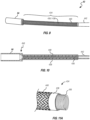
- Figures 9 and 10 illustrate a portion of the distal end of the outer sheath 82 and distal piece 84.
- Distal piece 84 can be made of a steel cylindrical tube having an inner diameter and length sized to receive the intravascular device, in a collapsed/pre-deployed configuration, within the lumen of distal piece 84.
- Distal piece 84 can include a plurality of microfabricated cuts (e.g., laser cuts) and a pair of continuous longitudinal spines located on opposite sides so that the tube can bend and flex substantially in a single plane.
- the outer sheath 82 can also include a bending portion 434 that can be attached to and located proximal to distal piece 84.
- Bending portion 434 can preferably have a sufficient length to surround and extend along that portion of the delivery system that is designed to bend and reorient, via the steerable catheter 80, to navigate through a patient's vasculature and/or heart to a target site for deploying the intravascular device.
- the bending portion 434 can include a cable tube or coil 436 surrounded by a braided structure 438 (sometimes collectively referred to as the "coil/braid portion 436/438") as shown in Figure 11A .
- FIG 11A is a perspective cutaway view of the sheath 82.
- the sheath 82 may have an inner cable tube or coil 436 and an outer braided sleeve or structure 438.
- Coil 436 can be made of or include a resilient coil material.
- the coil material may be stainless steel, nickel titanium (e.g., Nitinol), other metal alloy, a thermoplastic, other polymers such as PEEK, ceramics, carbon tubing, glass, or combinations thereof.
- coil 436 can be a stainless steel coil that has a droop value of 11:1 or higher.
- Coil 436 can be sized relative to the braided structure 438 such that the coil 436 has an outer diameter ("OD") in a relaxed state that is substantially the same as an inner diameter ("ID”) of braided structure 438 in a relaxed state.
- OD outer diameter
- ID inner diameter
- the coil 436 has an inner surface sufficiently smooth to allow the outer sheath 82 to effectively move over the steering catheter 80 and/or delivery catheter 78.
- the wire forming the coil 436 may have a "D" cross-sectional shape or other rounded shape such that the inward facing side is curved to minimize interference with other components translating within the coil 436.
- Figure 11C shows another view of the coil 436 showing a coil end 437 (which may represent a proximal end and/or a distal end).
- the coil end 437 is formed with a fully closed circumference. This allows the coil end 437 to be more readily welded, adhered, or otherwise attached to a connecting ring or hypotube section of the elongated member 70.
- the closed coil construction of the coil end 437 allows a laser weld to cover the full 360-degree circumference of the coil end 437.
- braided sleeve 438 may include a plurality of threads or fibers that are woven together.
- braided sleeve 438 may include a plurality of threads that extend at an angle to one another and are woven together in a repeating pattern. The plurality of threads may be woven in a diamond two wire two-under-two, over-two pattern; a half-load single wire over-one, one-under pattern; a full-load single wire over-two, under-two pattern; other alternating woven patterns; or combinations thereof.
- braided sleeve 438 may include a single thread routed substantially straight longitudinally through the plurality of threads.
- the threads may be round threads, elliptical threads, or flat threads.
- the threads may be made of, or include a variety of, reinforcement materials, such as, metals, metal alloys, thermoplastics, other polymers, ceramics, glasses or combinations thereof.
- the reinforcement material or materials may have a greater elastic modulus than the body material.
- a braided sleeve may include a mixture of threads with different properties, such as stainless steel threads woven with polymer threads.
- braided sleeve 438 may include a plurality of 304 stainless steel wires woven in a diamond pattern. Such an arrangement of a braided sleeve may include between 16 and 72 threads of stainless steel.
- braided sleeve 438 may include 24 strands, with each strand consisting of four wires.
- Coil 436 and braided sleeve 438 may be longitudinally fixed to one another at or near a proximal end of the outer sheath 82 and at or near the distal end of the outer sheath 82.
- the braided sleeve 438 may be welded or soldered to the coil 436 at a proximal end and at a distal end of the outer sheath 82.
- the braided sleeve 438 may be fixed to the coil 436 with an adhesive at a proximal end and a distal end of the outer sheath 82.
- the braided sleeve 438 may be fixed to the coil 436 via an intermediate element (e.g., an annular end cap) at a proximal end and a distal end of the outer sheath 82.
- braided sleeve 438 and coil 436 may be longitudinally fixed relative to one another at one or more points between a proximal end and a distal end of the outer sheath 82.
- braided sleeve 438 and the coil 436 may be longitudinally fixed relative to one another at a centerpoint.
- Hypotube 442 attached to the proximal end of bending portion 434 is a cut hypotube 442 that extends from bending portion 434 to the proximal end of the sheath 82.
- Hypotube 442 can include a plurality of slits and at least one longitudinally continuous spine that can preferably be continuous and uninterrupted along a longitudinal length of, and located at a fixed angular location on, hypotube 442.
- the longitudinally continuous spine of hypotube 442 may allow the sheath 82 to transmit tension force applied at a proximal end of the sheath 82 to a distal end of the sheath 82 without substantial elongation of the sheath 82.
- the longitudinally continuous spine hypotube 442 may allow the sheath 82 to transmit compression force applied at a proximal end to the distal end without substantial shortening of the sheath 82.
- some sheaths may exhibit a change in a longitudinal length of less than 30% during application of a compression force of 177.9 Newtons (40 pounds) or greater and/or application of a tension force of 177.9 Newtons (40 pounds) or greater.
- some sheaths may exhibit a change in a longitudinal length of less than 5% during application of a compression force of 177.9 Newtons (40 pounds) or greater and/or a tension force of 177.9 Newtons (40 pounds) or greater. In yet other examples, some sheaths may exhibit a change in a longitudinal length of less than 2% during application of a compression force of 177.9 Newtons (40 pounds) or greater and/or a tension force of 177.9 Newtons (40 pounds) or greater.
- the outer sheath 82 may transmit tension force without substantial change to the longitudinal length of the delivery sheath and may foreshorten by 5%, 10%, 15%, 20%, 25%, 30%, 40%, 50%, 75%, 100%, 150%, 200%, 250%, 300%, 350%), 400%) or any value therebetween during compression.
- the coil 436 may compress by a percentage of the initial longitudinal length of the sheath 82 before the coils contact one another and the coil 436 transmits compression forces along the longitudinal length thereof.
- the coil rings may have an initial (i.e., non-stressed) spacing of between 0.1mm and 5.0mm, between 1mm and 4mm, between 2mm to 3mm, or any values therebetween to provide a bending radius to navigate the anatomy toward and into a patient's heart.
- a flexible, fluid impermeable covering can be provided over the coil/braid portion 436/438, extending from the distal piece 84 to a location proximal the coil/braid portion 436/438.
- the delivery sheath 82 can also include a thin walled flexible cover 440 that extends from the distal piece 84 to the hypotube 442.
- Flexible cover 440 can be bonded at each end to the underlying structure, using one of a variety of different adhesives, thermal adhesives, UV bonded adhesive, or other techniques.
- Flexible cover 440 can be fabricated from Pelathane 80A, Tecoflex 72A, Texin 70A, Chronoflex 45D, or other suitable flexible material. Flexible cover 440 can also be coated with hydrophilic coating.
- the wall thickness of flexible cover 440 could be between 0.025mm to 0.152mm (0.001 " to 0.006") and preferably between 0.051 mm to 0.102mm (0.002" to 0.004"), and could have a diameter smaller than an outer diameter of the coil/braid portion 436/438.
- Flexible cover 440 can be bonded at its distal end to a proximal end portion of distal piece 84 and can be bonded at is proximal end to a distal end portion of hypotube 442.
- An intermediate portion of flexible cover 440 including that portion that extends over the flexible coil/braid portion 436/438, is not bonded to flexible coil/braid portion 436/438, but rather can preferably be press fit or otherwise able to move relative to, and stretch over, flexible coil/braid portion 436/438.
- Flexible cover 440 can preferably be made of a material with some elasticity and can be attached at opposing ends to underlying structure in a way that it is stretched and normally retains some tension, which can help avoid wrinkles forming in flexible cover 440 when the delivery sheath 82 is bent or otherwise flexed.
- flexible cover 440 can foreshorten by up to 20%, but can easily stretch so as not to impair the flexibility of coil/braid portion 436/438.
- coil/braid portion 436/438 can be stretched to the point where the braided structure 438 locks down on the coil 436 and can transmit high tension forces that may be needed to retract the outer sheath and distal piece 84 from the intravascular device. Conversely, if recapture of the intravascular device should become necessary, having the coil/braid portion 436/438 under a certain amount of compression in some circumstances can also provide an advantage.
- the stretching of flexible cover 440 also accommodates these relative movements of coil 436 and braided structure 438 within coil/braid portion 436/438.
- a mandrel can be disposed within the lumen of the delivery sheath 82, thereby stiffening delivery sheath 82, so that flexible cover 440 can be stretched and/or rolled over coil/braid portion 436/438, and then the opposing ends of flexible cover 440 can be sealed to the underlying structure.
- delivery sheath 82 can also be coupled to distal piece 84 via a swivel connection, generally indicated at 450.
- swivel connection 450 allows rotation of delivery sheath 82 by a few degrees, back and forth (i.e., alternating between clockwise rotation and counter-clockwise rotation) while at the same time moving the delivery system in a generally longitudinal direction. This rotational motion (during simultaneous longitudinal translation) helps to overcome some of the longitudinal forces that may resist insertion of delivery sheath 82 through a patient's vasculature.
- the intravascular device can be positioned within and covered by the distal piece 84 and can also be connected to the delivery catheter within the delivery system. Therefore, it might be desirable for an intermediate portion of the delivery sheath 82 (such as bending portion 434 and hypotube 442) to be free to swivel relative to the intravascular device and distal piece 84 while maintaining the intravascular device in stable and proper alignment with the delivery catheter 76.
- an intermediate portion of the delivery sheath 82 such as bending portion 434 and hypotube 442
- the distal piece 84 can be rotationally decoupled from distal end of the delivery sheath 82 by providing a swivel connection between a proximal end portion of distal piece 84 and the distal end portion of delivery sheath 82.
- a first swivel connection 450 can be formed between the proximal end of distal piece 84 and the distal end of bending portion 434.
- first swivel connection 450 can consist of an enlarged annular flange welded to the distal end of the coil/braided sleeve 436/438, and the enlarged annular flange can be interposed between a pair of annular rings or ridges formed on an inner surface of distal piece 84 at its proximal end. These structures cooperate to rotationally decouple the distal piece 84 from the bending portion 434, but at the same time maintain coupling between these elements in terms of longitudinal movement.
- first swivel connection 450 can also include one or more o-rings or other sealing components (not shown) positioned between the cooperating elements of the swivel to provide a fluid-tight swivel connection.
- a second example of first swivel connection 450 is illustrated in Figure 12 .
- a second swivel connection 452 can also be formed at the proximal end of the sheath to rotationally decouple the delivery sheath 82 from the control fixture 454 (shown schematically only).
- Second swivel connection 452 can include a pair of spaced-apart, annular ridges 456a and 456b formed on the exterior surface and adjacent to the proximal end of hypotube 442. Annular ridges 456a and 456b form an annular recess 458 between which a complementary aperture 460 formed in fixture 454 can be positioned.
- Second swivel connection 452 can also include one or more o-rings or other sealing components (not shown) positioned between the cooperating elements of the swivel to provide a fluid-tight swivel connection.
- fixture 454 can provide a two-piece clamp 462a and 462b that includes an annular recess 464 that receives an annular ring 466 formed on the exterior of hypotube 442 at its proximal end. Ring 466 can easily be welded to the proximal end of hypotube 442. As further shown in Figure 14 , the ring can also have a pin 468 that extends into a complementary groove 470 formed in clamp 462.
- Pin 468 and groove 470 cooperate to limit rotation of ring 466 relative to clamp 462 within a predetermined swivel angle range (e.g., between plus and minus 15°), but any swivel angle can be accommodated by simply extending or reducing the length of groove 470.
- a predetermined swivel angle range e.g., between plus and minus 15°
- an elastic bellows 472 can also be provided at the proximal end of hypotube 442.
- Bellows 472 allows a water tight connection, while at the same time accommodating rotational movement of hypotube 442.
- bellows 472 can stretch or compress when the delivery sheath 82 is moved longitudinally in a distal or proximal direction, as necessary, during delivery, deployment and/or release of the intravascular device.
- a standard luer lock connection 474 can be provided at the proximal end of bellows 472 to facilitate flushing of the interstitial spaces within delivery sheath 82 in preparation for an intervascular procedure.
- FIG. 15 illustrates one example of the steering catheter 80 in greater detail.
- the steering catheter 80 includes a proximal section 518, intermediate section 516, and a distal section 514.
- a steering ring 510 is connected at the distal end.
- a distal cap 512 positioned over the steering ring 510 provides an angled/rounded surface that allows the steering catheter 80 to more effectively move and slide against the outer sheath 82 without binding.
- the steering catheter 80 is formed as a hypotube.
- the proximal section 518 may remain uncut, while the intermediate section 516 and distal section 514 may be cut (e.g., laser cut) to increase flexibility.
- a polymer layer surrounds the steering catheter and forms the outer layer.
- the steering catheter 80 is rotationally keyed to the outer sheath 82.
- the outer sheath 82 may include cut patterns and/or other features which are arranged to provide particular bending directions. In this example, because bending of the outer sheath 82 depends upon curving of the steering catheter 80, rotational alignment of the outer sheath 82 to the steering catheter 80 is beneficial.
- These components may be keyed together using a key and corresponding keyway feature, slots and corresponding tabs, or other rotational keying mechanism known in the art.
- alignment markers can be provided at the handle assembly to visually indicate alignment.
- the distal section 514 is cut with a pattern which allows a bending radius of about 15 mm or less (e.g., 5 to 15 mm).
- the intermediate section 516 is cut to allow a bending radius of about 30 to 45 cm.
- the proximal section is uncut to provide the steering catheter 80 with sufficient stiffness, torquability, and pushability.
- the steering catheter 80 may be sized so that the inner diameter is about 3.81 mm to 5.08mm (about 0.15 to 0.20 inches), with a wall thickness of about 1.016mm to 1.270mm (about 0.040 to 0.050 inches).
- the steering catheter 80 includes a set of tension cables which pass from the steering catheter handle to the steering ring 510.
- Adjusting tension of the tension cables allows the steering catheter 80 to be curved.
- the tension cables have a diameter that allows them to fit within the wall of the outer layer of the steering catheter 80, such as a diameter of about 0.254mm to 0.508mm (about 0.01 to 0.02 inches), or about 0.381 mm to 0.457mm (about 0.015 to 0.018 inches).
- Figure 16 illustrates an example of a series of compound bends that the steering catheter 80 may perform during the delivery, repair, recapture, or repositioning of the intravascular device. While accessing the mitral annulus, the steering catheter 80 may be steered in at least two planes of motion. The two planes of motion may be substantially perpendicular to one another.
- the steering catheter 80 has a first bend 502 with a first bend angle 503 measured between a first longitudinal axis 506 and a second longitudinal axis 507.
- the first bend angle 503 may be in a range having an upper value, a lower value, or an upper and lower value including any of 60°, 65°, 70°, 75°, 80°, 85°, 90°, 95°, 100°, 105°, 110°, 115°, 120°, 125°, 130°, 135°, 140°, 145°, 150°, 155°, 160°, 165°, 170°, or 175°.
- the first bend angle 503 is in a range of about 90° to 120°, or is about 105°.
- the steering catheter 80 has a second bend 504 having a second bend angle 505.
- the second bend 504 is formed between a third longitudinal axis 508 and the second longitudinal axis 507.
- the second bend 504 may also have a rotational angle 509 relative to a plane in which the first longitudinal axis 506 and the second longitudinal axis 507 lie.
- the rotational angle 509 is relative to the amount of rotation of the third longitudinal axis 508 relative to the direction of the first bend 502.
- the second bend angle 505 may be in a range having an upper value, a lower value, or an upper and lower value including any of 60°, 65°, 70°, 75°, 80°, 85°, 90°, 95°, 100°, 105°, 110°, 115°, 120°, 125°, 130°, 135°, 140°, 145°, 150°, 155°, 160°, 165°, 170°, or 175°.
- the second bend angle 505 is in a range of about 80° to 110°, or is about 90°.
- the rotational angle 509 may be in a range having an upper value, a lower value, or an upper and lower value including any of 30°, 35°, 40°, 45°, 50°, 55°, 60°, 65°, 70°, 75°, 80°, 85°, 90°, 100°, 110°, 120°, 130°, 140°, 150°, or 160°. In one arrangement, the rotational angle 509 may be in a range of 45° to 135° or may be about 60°.
- Figure 17 is a cross-sectional view of the outer layer of the steering catheter 80, showing a series of lumen 581 for routing of the tension cables 583.
- the lumen 581 are held open with micro-coils, at least at the distal section 514 where greater bending takes place. The micro-coils maintain effective flexibility while also keeping the lumen clear and open, while minimizing bowing, for proper operation of the tension cables 583.
- a braid material covers the lumen 581 in the intermediate section 516 and/or proximal section 518.
- the polymer outer layer is a polyether block amide. The polymer outer layer may be formed to be have greater flexibility at the distal section 514 than at the intermediate and proximal sections 516, 518.
- the polymer layer at the distal section 514 may have a durometer of about 30 to 40D, or about 35D, whereas at the intermediate section 516 and/or proximal section 518 the polymer layer has a durometer of about 55 to 85D, or about 65 to 75D.
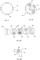
- FIG 18 shows the distal steering ring 510.
- the steering ring 510 includes a set of distal holes 515. Each pair of distal holes 515 surrounds a saddle feature 512.
- a tension cable may be routed distally to the steering ring 510, through one of the distal holes 515, and then over the adjacent saddle feature 512 and back through the opposite distal hole 515.
- the saddle feature 512 has a curved surface on which the overlying tension cable rests, which minimizes pinching of the tension cable.
- the steering ring 510 may also include one or more proximal holes 517, which can be used for attaching the steering ring 510 to the distal end of the steering catheter 80 (via adhesives and/or laser welding, for example).
- FIG 19A shows various cutting patterns that can be used in different sections of the steering catheter 80 (and corresponding sections of the outer sheath 82) to produce the desired bends.
- Each section can include cut patterns that can include one or more slits 556 and/or one or more island cuts 558.
- the slits 556 may transmit longitudinal force along the catheter and also allow expansion of the catheter when it is deflected in a direction opposite the slit 556.
- the island cuts 558 may allow compression of the catheter when it is deflected in a direction of the island cuts 558.
- slits 556 and island cuts 558 when located on opposite sides from one another, may direct preferential bending of the catheter, as shown by exemplary bend 504 in Figure 19B .
- a cutting pattern can include five sections or regions 560, 562, 564, 566 and 568, with different cut patterns in each section. Such sections may be arranged as needed to provide the desired compound curve profile.
- a first section 560 can include a plurality of holes radially spaced about the periphery of the catheter. These holes provide flexibility without forming a particular bending direction.
- a second section 562 provides for bending in a first direction
- a third section 564 is similar to the second section 562 but with smaller sized and more closely spaced island cuts 558
- a fourth section 564 provides for bending in a second direction
- a fifth section 566 includes multiple slits for adding flexibility without forming a particular bending direction.
- island cuts 558 are depicted as diamond-shaped, the island cuts 558 may have one or more other shapes, such as square, rhombohedral, triangular, rectangular, circular, oblong, other elliptical, other polygonal, irregular, or combinations thereof.
- FIG. 20 illustrates one example of the delivery catheter 78 in greater detail.
- the delivery catheter 78 includes a proximal section 604 and a distal section 602.
- the delivery catheter 78 includes a seal 606 and an o-ring 608 for forming a fluid tight seal at the delivery catheter holder 136.
- the distal section 602 is formed as a compression coil.
- the compression coil provides the delivery catheter 78 with ability to effectively push the intravascular device through the steering catheter 80 as part of deployment.
- the compression coil also provides good flexibility for advancing within the compound curve of the steering catheter 80.
- the proximal section 604 is formed as a cut (e.g., laser cut) hypotube.
- Figure 21A illustrates one example of a distal tip 988 having an active element 908 to aid in removal of the distal tip 988 in the case that it becomes caught or tangled in chordae.
- the illustrated arrangement includes distal portion 902, a proximal section 904, and a lip 906.
- the diameter of the tip at the lip 906 is sized to match an inner diameter of the distal piece so that the lip 906 can be seated within the distal piece.
- the active element 908 may be formed as a thread or spiraled set of grooves.
- the grooves preferably extend from the proximal end of the tip 988 onto the lip 906.
- the grooves of the active element 908 may have a pitch of about 30 to 60 degrees. The structure of such an active element allows the tip 988 to be "screwed out" of entangled chordae by rotating the guidewire tube to which the tip 988 is connected.
- the tip 988 may be coupled to the guidewire tube 86 using an adhesive, welding, a friction fit, a threaded connection, and/or other suitable connection means.
- Figure 21B illustrates, in cross-sectional view, one example where the tip 988 is formed as two separate pieces.
- the distal piece 910 and proximal piece 912 may be fit together at a snap fit feature 914, as shown.
- the distal piece 910 and proximal piece 912 may include corresponding threads to allow a threaded connection
- the tip 988 may include a cutting ring fitting (e.g., metal or plastic) configured to deform to hold the separate pieces in position when the separate pieces are screwed or snapped together.
- the guidewire tube 86 may also include a holding ring 916 that the two-piece tip 988 can be positioned around and mechanically interfere with.
- the holding ring 916 may also function as a mechanical stopper.
- the holding ring 916 may also be formed of a radiopaque material.
- a pouch or cavity of cyanoacrylate or other suitable adhesive is included in one of the separate pieces, and is positioned to break open to release the adhesive when the separate pieces are connected.
- Figures 22A through 22E illustrate an exemplary approach for delivering the intravascular device to the mitral annulus.
- the intravascular device, distal piece, and other associated components may be relatively rigid and/or long, which can complicate delivery.
- Figure 22A illustrates an example of a delivery member 270 and distal piece 284 positioned in the right atrium 152 of a heart.
- a guidewire 287 may be inserted through the intra-atrial septum and into the left atrium 156 of the heart.
- the intravascular device is then urged longitudinally through the intra-atrial septum 154 to the left atrium 156, as shown in Figure 22B .
- Figure 22B shows the delivery member 270 and positioned in the left atrium 156.
- the distal piece 284 may have a longitudinal length such that the distal end of the device strikes the wall of the left atrium opposite the intra-atrial septum 154 if the distal end of the device is positioned over the mitral annulus 158 before deflecting/curving the delivery member 270.
- the delivery member 302 is advanced until the distal tip is positioned just beyond the intra-atrial septum and just into the left atrium 156.
- the distal tip may be located in the left atrium 156.
- the distal section of the device may be deflected/curved an amount toward the mitral annulus 158 by steering the steering catheter toward the target location.
- the delivery member 270 may be longitudinally advanced further to position a greater amount of the distal piece 284 through the septum and into the left atrium, as shown in Figure 22D .
- the device may be iteratively deflected/curved and advanced as necessary to achieve the desired position substantially normal to the mitral annulus as shown in Figure 22E , while avoiding hitting against the cardiac wall.
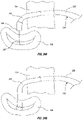
- the right atrium 152 of a human heart provides limited space in which to bend or steer a catheter from the direction in which the inferior vena cava enters the heart to a direction in line with the intra-atrial septum. For longer interventional devices, it may be more difficult to make the necessary bend within the confines of the right atrium 152.
- Figure 23A graphically depicts a path generally taken by a conventional delivery catheter through the right atrium 152 and through the intra-atrial septum to the left atrium 156.
- the delivery member may be configured to produce a first bend at a first location 206 near a distal end 210, while also producing a second bend at a second location 208 proximal the first location 206.
- This can provide an improved path for the elongated delivery member, as graphically illustrated in Figure 23B , that can provide additional space in which to allow the distal end portion of the catheter and intravascular device to make the turn within the right atrium 152.
- the second bend at the second location 208 can be in a direction substantially opposite to that of the first bend at the first location 206.
- the second bend pushes or "kicks" the elongated delivery member in the opposite direction from the movement of the distal tip near the first location 206. This movement urges the delivery member near the first bend location 206 to move toward the wall of the right atrium 152 and creates more space for the distal tip 210 to bend and penetrate the intra-atrial septum.
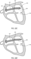
- Figures 24A and 24B illustrate a maneuver for advancing the distal end of the delivery member 270 into the mitral annulus 158 after the distal piece 284 has been properly positioned above the mitral annulus 158 via curves/bends 220 and 222.
- the delivery member 270 is advanced distally forward through the mitral annulus although the compound curve shape of curves 220 and 222 is maintained.
- this is possible because the outer sheath, distal piece, delivery catheter, suture catheter, and guidewire tube may be advanced relative to the steering catheter while the steering catheter maintains its compound curve shape.
- a stated value should therefore be interpreted broadly enough to encompass values that are at least close enough to the stated value to perform a desired function or achieve a desired result.
- the stated values include at least the variation to be expected in a suitable manufacturing or production process, and may include values that deviate by less than or equal to 5%, 1%, 0.1%, or 0.01% of a stated value.
Landscapes
- Health & Medical Sciences (AREA)
- Life Sciences & Earth Sciences (AREA)
- Engineering & Computer Science (AREA)
- Biomedical Technology (AREA)
- Veterinary Medicine (AREA)
- General Health & Medical Sciences (AREA)
- Heart & Thoracic Surgery (AREA)
- Public Health (AREA)
- Animal Behavior & Ethology (AREA)
- Cardiology (AREA)
- Hematology (AREA)
- Biophysics (AREA)
- Anesthesiology (AREA)
- Pulmonology (AREA)
- Transplantation (AREA)
- Vascular Medicine (AREA)
- Oral & Maxillofacial Surgery (AREA)
- Mechanical Engineering (AREA)
- Surgery (AREA)
- Nuclear Medicine, Radiotherapy & Molecular Imaging (AREA)
- Medical Informatics (AREA)
- Molecular Biology (AREA)
- Surgical Instruments (AREA)
- Prostheses (AREA)
Claims (15)
- Zuführsystem (190) zum Zuführen einer implantierbaren intravaskulären Vorrichtung zu einer anvisierten Herzklappe, wobei das Zuführsystem (190) umfasst:eine Griffbaugruppe (130);ein langgestrecktes Zuführelement (70), das mit der Griffbaugruppe (130) gekoppelt ist und sich distal von der Griffbaugruppe (130) erstreckt, wobei das Zuführelement (70) ein distales Ende aufweist und konfiguriert ist, um lösbar an eine intravaskuläre Vorrichtung zu koppeln, wobei das Zuführelement (70) ferner umfasst:eine Außenhülle (82) mit einem distalen Teil (84) proximal zu einer atraumatischen distalen Spitze (88) des Zuführelements (70), wobei das distale Teil (84) konfiguriert ist, um die intravaskuläre Vorrichtung in einer noch unentfalteten Konfiguration aufzunehmen;ein Steuerbauteil (80), das konfiguriert ist, um das Zuführelement (70) in einer zusammengesetzten Kurve zu krümmen, die eine intravaskuläre Zuführung des Zuführelements (70) zu der anvisierten Herzklappe ermöglicht;einen Zuführkatheter (78), der konfiguriert ist, um die intravaskuläre Vorrichtung relativ zu der Außenhülle (82) in Längsrichtung zu verschieben;einen Nahtkatheter (72) mit einem oder mehreren Bändern, die konfiguriert sind, um lösbar mit der intravaskulären Vorrichtung gekoppelt zu werden, wobei der Nahtkatheter (72) relativ zum Zuführkatheter (78) in Längsrichtung verschiebbar ist, um eine Einstellung der Spannung in den ein oder mehreren Bändern zu ermöglichen; undein Führungsdrahtrohr (86), das sich durch das Zuführelement (70) zum distalen Ende des Zuführelements (70) erstreckt, wo es an der distalen Spitze (88) befestigt ist, wobei das Führungsdrahtrohr (86) relativ zum Nahtkatheter (72) linear verschiebbar ist; der Nahtkatheter (72) innerhalb des Zuführkatheters (78) angeordnet ist, und das Führungsdrahtrohr (86) innerhalb des Nahtkatheters (72) angeordnet ist.
- Zuführsystem (190) nach Anspruch 1, bei dem das Steuerbauteil (80) ein Steuerkatheter ist, der in der Außenhülle (82) angeordnet ist.
- Zuführsystem (190) nach Anspruch 2, bei dem der Steuerkatheter (80) eine Mehrzahl von Spannkabeln (583) und ein entsprechendes Spannkabellumen (581) aufweist, wobei die Spannkabel (583) für die Steuerung des Steuerkatheters (80) durch Einstellen der Spannung in den Spannkabeln (583) sorgen; und optional, bei dem jedes Spannkabellumen (581) eine Mikrospule entlang mindestens eines distalen Abschnitts (514) des Steuerkatheters (80) aufweist.
- Zuführsystem (190) nach Anspruch 2, bei dem der Steuerkatheter (80) als Hypotubus ausgebildet ist, wobei der Hypotubus ein Schnittmuster aufweist, das die Flexibilität des Hypotubus relativ zu einem ungeschnittenen Abschnitt des Hypotubus erhöht; und optional, bei dem der Hypotubus einen distalen Abschnitt (514), einen Zwischenabschnitt (516) und einen proximalen Abschnitt (518) umfasst, wobei der distale Abschnitt (514) ein Schnittmuster aufweist, das einen Biegeradius von etwa 5 bis 15 mm ermöglicht, und der Zwischenabschnitt (516) ein Schnittmuster aufweist, das einen größeren Biegeradius als der distale Abschnitt (514) bereitstellt.
- Zuführsystem (190) nach Anspruch 1, bei dem das distale Teil (84) eine Mehrzahl von mikrogefertigten Schnitten entlang mindestens eines proximalen Abschnitts des distalen Teils (84) aufweist, wobei die mikrogefertigten Schnitte konfiguriert sind, um eine Biegung in einer einzigen Ebene zu bewirken.
- Zuführsystem (190) nach Anspruch 1, bei dem die Außenhülle (82) eine Spule (436) und eine geflochtene Hülse (438) aufweist; und optional, bei dem die Spule (436) aus einem Spulendraht mit einem "D"-förmigen Querschnitt gebildet ist.
- Zuführsystem (190) nach Anspruch 6, bei dem die Außenhülle (82) ferner eine flüssigkeitsundurchlässige, flexible Polymerabdeckung (440) aufweist, die über der Spule (436) und der geflochtenen Hülse (438) angeordnet ist.
- Zuführsystem (190) nach Anspruch 1, bei dem das distale Teil (84) vom Rest der Außenhülle (82) drehentkoppelt ist.
- Zuführsystem (190) nach Anspruch 1, bei dem die Außenhülle (82) an die Griffbaugruppe (130) mit einer Schwenkverbindung gekoppelt ist, die es der Außenhülle (82) ermöglicht, relativ zu der Griffbaugruppe (130) zu schwenken.
- Zuführsystem (190) nach Anspruch 1, bei dem der Zuführkatheter (78) zumindest an einem distalen Abschnitt (602) eine Kompressionsspule aufweist.
- Zuführsystem (190) nach Anspruch 2, bei dem die Griffbaugruppe (130) von einer Halterung (176) getragen ist, wobei die Halterung (176) eine Mehrzahl von Stützen (166, 169, 170, 171) aufweist, die die Außenhülle (82), einen Steuerkathetergriff (132), einen Zuführkatheterhalter (136) und einen Nahtkatheterhalter (138) tragen, wobei die Halterung (176) einstellbare Steuerungen aufweist, die eine Bewegung von Komponenten des Zuführelements (70) relativ zu anderen Komponenten des Zuführelements (70) ermöglichen.
- Zuführsystem (190) nach Anspruch 11, bei dem die Halterung (176) umfasst:
eine Einstelleinrichtung für die Zuführvorrichtung, um die gesamte Zuführvorrichtung relativ zu einer Basis (161) in Längsrichtung zu verschieben; eine Einstelleinrichtung (174) für die äußere Hülle, um die Außenhülle (82) relativ zu anderen Komponenten des Zuführelements (70) zu verschieben; oder eine Entfaltungseinstelleinrichtung (175), um den Zuführkatheter (78), die Außenhülle (82) und den Nahtkatheter (72) relativ zum Steuerkatheter (80) zu verschieben. - Zuführsystem (190) nach Anspruch 1, bei dem die Griffbaugruppe (130) einen Zuführkatheterhalter (136), einen Nahtkatheterhalter (138) und eine Nahtkatheter-Einstellvorrichtung (139) aufweist, wobei die Nahtkatheter-Einstellvorrichtung (139) mit dem Zuführkatheterhalter (136) verbunden ist, und der Nahtkatheterhalter (138) Gewinde aufweist, die mit entsprechenden Gewinden der Nahtkatheter-Einstellvorrichtung (139) so in Eingriff stehen, dass eine Drehung der Nahtkatheter-Einstellvorrichtung (139) den Nahtkatheterhalter (138) relativ zu dem Zuführkatheterhalter (136) verschiebt.
- Zuführsystem (190) nach Anspruch 2, bei demdas Führungsdrahtrohr (86) sich durch das distale Teil (84) zu der daran angebrachten distalen Spitze (88) erstreckt, wobei die distale Spitze (88) konfiguriert ist, um sich mit einer distalen Seite des distalen Teils (84) zu verbinden oder daran anzuliegen; unddie Griffanordnung (130) umfasst:einen Außenhüllenhalter (131), der mit der Außenhülle (82) am proximalen Ende der Außenhülle (82) verbunden ist;einen Steuerkathetergriff (132), der proximal des Außenhüllenhalters (131) angeordnet ist, wobei ein proximales Ende des Steuerkatheters (80) mit dem Steuerkathetergriff (132) gekoppelt ist und der Steuerkatheter (80) sich von dort distal in die Außenhülle (82) erstreckt;einen Zuführkatheterhalter (136), der proximal des Steuerkathetergriffs (132) angeordnet ist, wobei ein proximales Ende des Zuführkatheters (78) mit dem Zuführkatheterhalter (136) gekoppelt ist und der Zuführkatheter (78) sich von dort distal in den Steuerkatheter (80) erstreckt; undeinen Nahtkatheterhalter (138), der proximal des Zuführkatheterhalters (136) angeordnet ist, wobei ein proximales Ende des Nahtkatheters (72) mit dem Nahtkatheterhalter (138) gekoppelt ist und sich von dort distal in den Zuführkatheter (78) erstreckt.
- Zuführsystem (190) nach Anspruch 2, bei demdas Führungsdrahtrohr (86) sich durch das distale Teil (84) zu der daran befestigten distalen Spitze (88) erstreckt, wobei die distale Spitze (88) konfiguriert ist, um sich mit einer distalen Seite des distalen Teils (84) zu verbinden oder daran anzuliegen; unddie Griffbaugruppe (130) einen Außenhüllenhalter (131), einen Steuerkathetergriff (132), einen Zuführkatheterhalter (136), einen Nahtkatheterhalter (138) und eine Halterung (176) umfasst, die konfiguriert ist, um die Griffbaugruppe (130) zu tragen, wobei die Halterung (176) umfasst:eine Einstellvorrichtung für die Zuführvorrichtung, um die gesamte Zuführvorrichtung relativ zu einer Basis (161) in Längsrichtung zu verschieben;eine Einstellvorrichtung (174) für die Außenhülle, um die Außenhülle (82) relativ zu anderen Komponenten des Zuführelements (70) zu verschieben; undeine Entfaltungseinstellvorrichtung (175) zum Verschieben des Einführungskatheters (78), der Außenhülle (82) und des Nahtkatheters (72) relativ zu dem Steuerkatheter (80).
Applications Claiming Priority (23)
| Application Number | Priority Date | Filing Date | Title |
|---|---|---|---|
| US201662368702P | 2016-07-29 | 2016-07-29 | |
| US201662368683P | 2016-07-29 | 2016-07-29 | |
| US201662368711P | 2016-07-29 | 2016-07-29 | |
| US201662368695P | 2016-07-29 | 2016-07-29 | |
| US201662380246P | 2016-08-26 | 2016-08-26 | |
| US201662380799P | 2016-08-29 | 2016-08-29 | |
| US201662380888P | 2016-08-29 | 2016-08-29 | |
| US201662380795P | 2016-08-29 | 2016-08-29 | |
| US201662380862P | 2016-08-29 | 2016-08-29 | |
| US201662380873P | 2016-08-29 | 2016-08-29 | |
| US201662404511P | 2016-10-05 | 2016-10-05 | |
| US201662422426P | 2016-11-15 | 2016-11-15 | |
| US201662430143P | 2016-12-05 | 2016-12-05 | |
| US201662430149P | 2016-12-05 | 2016-12-05 | |
| US201662436887P | 2016-12-20 | 2016-12-20 | |
| US201662436922P | 2016-12-20 | 2016-12-20 | |
| US201662436985P | 2016-12-20 | 2016-12-20 | |
| US201662436913P | 2016-12-20 | 2016-12-20 | |
| US201662436926P | 2016-12-20 | 2016-12-20 | |
| US201662436918P | 2016-12-20 | 2016-12-20 | |
| US201762462776P | 2017-02-23 | 2017-02-23 | |
| US15/662,142 US11324495B2 (en) | 2016-07-29 | 2017-07-27 | Systems and methods for delivering an intravascular device to the mitral annulus |
| PCT/US2017/044481 WO2018023052A1 (en) | 2016-07-29 | 2017-07-28 | Systems and methods for delivering an intravascular device to the mitral annulus |
Publications (2)
| Publication Number | Publication Date |
|---|---|
| EP3490657A1 EP3490657A1 (de) | 2019-06-05 |
| EP3490657B1 true EP3490657B1 (de) | 2023-02-08 |
Family
ID=61011410
Family Applications (1)
| Application Number | Title | Priority Date | Filing Date |
|---|---|---|---|
| EP17749090.1A Active EP3490657B1 (de) | 2016-07-29 | 2017-07-28 | Systeme zur bereitstellung einer intravaskulären vorrichtung für den mitralring |
Country Status (7)
| Country | Link |
|---|---|
| US (1) | US11324495B2 (de) |
| EP (1) | EP3490657B1 (de) |
| CN (2) | CN113952079A (de) |
| AU (1) | AU2017301748B2 (de) |
| CR (1) | CR20190107A (de) |
| SG (1) | SG11201900817XA (de) |
| WO (1) | WO2018023052A1 (de) |
Families Citing this family (86)
| Publication number | Priority date | Publication date | Assignee | Title |
|---|---|---|---|---|
| US11660420B2 (en) | 2018-09-17 | 2023-05-30 | Seigla Medical, Inc. | Catheters and related devices and methods of manufacture |
| US20200086089A1 (en) * | 2018-09-17 | 2020-03-19 | Seigla Medical, Inc. | Systems, methods and apparatus for guiding and supporting catheters such as stent delivery catheters |
| US11547835B2 (en) | 2018-09-17 | 2023-01-10 | Seigla Medical, Inc. | Systems, methods and apparatus for guiding and supporting catheters and methods of manufacture |
| US12220538B2 (en) | 2008-12-08 | 2025-02-11 | Scientia Vascular, Inc. | Micro-fabricated intravascular devices having varying diameters |
| CN102639303B (zh) | 2008-12-08 | 2015-09-30 | 血管科学有限公司 | 用于在产品中形成切口的微切割机 |
| US11406791B2 (en) | 2009-04-03 | 2022-08-09 | Scientia Vascular, Inc. | Micro-fabricated guidewire devices having varying diameters |
| US8579964B2 (en) | 2010-05-05 | 2013-11-12 | Neovasc Inc. | Transcatheter mitral valve prosthesis |
| US9308087B2 (en) | 2011-04-28 | 2016-04-12 | Neovasc Tiara Inc. | Sequentially deployed transcatheter mitral valve prosthesis |
| US9554897B2 (en) | 2011-04-28 | 2017-01-31 | Neovasc Tiara Inc. | Methods and apparatus for engaging a valve prosthesis with tissue |
| WO2017100927A1 (en) | 2015-12-15 | 2017-06-22 | Neovasc Tiara Inc. | Transseptal delivery system |
| JP7006940B2 (ja) | 2016-01-29 | 2022-01-24 | ニオバスク ティアラ インコーポレイテッド | 流出の閉塞を回避するための人工弁 |
| US11052228B2 (en) | 2016-07-18 | 2021-07-06 | Scientia Vascular, Llc | Guidewire devices having shapeable tips and bypass cuts |
| US11207502B2 (en) | 2016-07-18 | 2021-12-28 | Scientia Vascular, Llc | Guidewire devices having shapeable tips and bypass cuts |
| US10639151B2 (en) | 2016-07-29 | 2020-05-05 | Cephea Valve Technologies, Inc. | Threaded coil |
| US10661052B2 (en) | 2016-07-29 | 2020-05-26 | Cephea Valve Technologies, Inc. | Intravascular device delivery sheath |
| US10646689B2 (en) | 2016-07-29 | 2020-05-12 | Cephea Valve Technologies, Inc. | Mechanical interlock for catheters |
| US11324495B2 (en) | 2016-07-29 | 2022-05-10 | Cephea Valve Technologies, Inc. | Systems and methods for delivering an intravascular device to the mitral annulus |
| US10974027B2 (en) | 2016-07-29 | 2021-04-13 | Cephea Valve Technologies, Inc. | Combination steerable catheter and systems |
| US10933216B2 (en) | 2016-08-29 | 2021-03-02 | Cephea Valve Technologies, Inc. | Multilumen catheter |
| US11045315B2 (en) | 2016-08-29 | 2021-06-29 | Cephea Valve Technologies, Inc. | Methods of steering and delivery of intravascular devices |
| US11109967B2 (en) | 2016-08-29 | 2021-09-07 | Cephea Valve Technologies, Inc. | Systems and methods for loading and deploying an intravascular device |
| US10874512B2 (en) | 2016-10-05 | 2020-12-29 | Cephea Valve Technologies, Inc. | System and methods for delivering and deploying an artificial heart valve within the mitral annulus |
| WO2018090148A1 (en) | 2016-11-21 | 2018-05-24 | Neovasc Tiara Inc. | Methods and systems for rapid retraction of a transcatheter heart valve delivery system |
| US11452541B2 (en) | 2016-12-22 | 2022-09-27 | Scientia Vascular, Inc. | Intravascular device having a selectively deflectable tip |
| US10653523B2 (en) | 2017-01-19 | 2020-05-19 | 4C Medical Technologies, Inc. | Systems, methods and devices for delivery systems, methods and devices for implanting prosthetic heart valves |
| CN110691626B (zh) | 2017-05-26 | 2022-03-18 | 血管科学有限责任公司 | 具有非螺旋切口布置的微制造医疗装置 |
| CN111263622A (zh) | 2017-08-25 | 2020-06-09 | 内奥瓦斯克迪亚拉公司 | 顺序展开的经导管二尖瓣假体 |
| US12318288B2 (en) | 2017-10-30 | 2025-06-03 | Cephea Valve Technologies, Inc. | Insert for distal end cap |
| EP3720390B1 (de) | 2018-01-25 | 2024-05-01 | Edwards Lifesciences Corporation | Einführsystem zur unterstützten rückgewinnung oder neupositionierung eines klappenersatzes nach dem einsetzen |
| US11305095B2 (en) * | 2018-02-22 | 2022-04-19 | Scientia Vascular, Llc | Microfabricated catheter having an intermediate preferred bending section |
| CN108852490B (zh) * | 2018-04-08 | 2020-12-01 | 管廷进 | 脊柱椎弓根内固定棒弯折装置及其工作方法 |
| WO2020014764A2 (en) * | 2018-07-18 | 2020-01-23 | Braile Biomédica Indústria Comércio E Representações Ltda. | Multi lumen release device |
| US12539389B2 (en) | 2018-09-17 | 2026-02-03 | Seigla Medical, Inc. | Catheters and related devices and methods of manufacture |
| AU2019374743B2 (en) | 2018-11-08 | 2022-03-03 | Neovasc Tiara Inc. | Ventricular deployment of a transcatheter mitral valve prosthesis |
| US11724068B2 (en) | 2018-11-16 | 2023-08-15 | Cephea Valve Technologies, Inc. | Intravascular delivery system |
| CN109350324B (zh) * | 2018-12-06 | 2023-11-14 | 南京法迈特科技发展有限公司 | 远端可弯曲的支架植入装置 |
| US12011555B2 (en) | 2019-01-15 | 2024-06-18 | Scientia Vascular, Inc. | Guidewire with core centering mechanism |
| US12544226B2 (en) | 2019-02-14 | 2026-02-10 | 4C Medical Technologies, Inc. | Hydrophilic skirt for paravalvular leak mitigation and fit and apposition optimization for prosthetic heart valve implants |
| JP7430732B2 (ja) | 2019-03-08 | 2024-02-13 | ニオバスク ティアラ インコーポレイテッド | 回収可能補綴物送達システム |
| US20220152382A1 (en) * | 2019-03-15 | 2022-05-19 | Biotronik Se & Co. Kg | Catheter Device for Implanting a Medical Device |
| US11491006B2 (en) | 2019-04-10 | 2022-11-08 | Neovasc Tiara Inc. | Prosthetic valve with natural blood flow |
| US12186188B2 (en) | 2019-05-01 | 2025-01-07 | Twelve, Inc. | Support devices for transcatheter delivery system handles |
| US11411974B2 (en) | 2019-05-17 | 2022-08-09 | Citrix Systems, Inc. | Applying policies to APIs for service graph |
| EP4729110A2 (de) | 2019-05-20 | 2026-04-22 | Neovasc Tiara Inc. | Einführvorrichtung mit hämostasemechanismus |
| WO2020257643A1 (en) | 2019-06-20 | 2020-12-24 | Neovasc Tiara Inc. | Low profile prosthetic mitral valve |
| CN111067668B (zh) * | 2019-12-27 | 2022-04-22 | 先健科技(深圳)有限公司 | 测力装置 |
| US12178975B2 (en) | 2020-01-23 | 2024-12-31 | Scientia Vascular, Inc. | Guidewire having enlarged, micro-fabricated distal section |
| US12343485B2 (en) | 2020-01-23 | 2025-07-01 | Scientia Vascular, Inc. | High torque guidewire device |
| US20210244916A1 (en) * | 2020-02-12 | 2021-08-12 | Cephea Valve Technologies, Inc. | Systems, methods, and devices for controlling re-sheathing forces |
| KR20220150321A (ko) * | 2020-03-06 | 2022-11-10 | 에드워즈 라이프사이언시스 코포레이션 | 볼 조인트가 있는 노즈콘을 갖는 전달 장치 |
| US11813414B2 (en) * | 2020-03-10 | 2023-11-14 | Stryker Corporation | Control systems for shapeable catheters |
| US12036119B2 (en) | 2020-04-20 | 2024-07-16 | Cephea Valve Technologies, Inc. | Delivery system for heart valve replacement |
| US11701214B2 (en) | 2020-05-22 | 2023-07-18 | Cephea Valve Technologies, Inc. | Prosthetic heart valve packaging and attachment assembly |
| EP4171444B1 (de) * | 2020-07-23 | 2025-10-01 | Edwards Lifesciences Corporation | Andockstation für herzklappenprothese |
| CN111643228B (zh) * | 2020-08-04 | 2020-12-11 | 上海申淇医疗科技有限公司 | 一种用于二尖瓣修复的输送系统 |
| BR112023003611A2 (pt) | 2020-08-28 | 2023-04-04 | Inqb8 Medical Tech Llc | Válvula cardíaca protética |
| KR20230061453A (ko) * | 2020-09-03 | 2023-05-08 | 아이엔큐비8 메디컬 테크놀로지스 엘엘씨 | 인공 심장 판막용 송달 시스템 및 방법 |
| CN112155787A (zh) * | 2020-09-28 | 2021-01-01 | 金仕生物科技(常熟)有限公司 | 一种介入二尖瓣膜输送系统定位装置 |
| US12296112B2 (en) | 2020-10-05 | 2025-05-13 | Scientia Vascular, Inc. | Microfabricated catheter devices with high axial strength |
| US20230372079A1 (en) * | 2020-10-12 | 2023-11-23 | Ascense Medical Gmbh | Vascular stent-graft |
| US12551654B2 (en) | 2020-10-22 | 2026-02-17 | Boston Scientific Scimed, Inc. | Compression resistant sheath |
| US11925556B2 (en) | 2020-10-26 | 2024-03-12 | St. Jude Medical, Cardiology Division, Inc. | Passive alignment of commissures in prosthetic heart valve implantation |
| US11197755B1 (en) | 2020-10-28 | 2021-12-14 | Occam Labs LLC | Systems, devices and methods for folded unibody heart valve stents |
| CN115397367B (zh) * | 2020-12-03 | 2026-04-17 | 卡迪尔维尔福股份有限公司 | 经腔递送系统 |
| CN114831733B (zh) * | 2021-02-02 | 2024-09-27 | 沛嘉医疗科技(苏州)有限公司 | 手术机器人系统 |
| US11246726B1 (en) | 2021-02-10 | 2022-02-15 | Occam Labs LLC | Systems, devices and methods for delivery systems |
| WO2023285967A1 (en) * | 2021-07-16 | 2023-01-19 | Medtronic, Inc. | Transcatheter valve delivery system with omnidirectional steering and methods of use thereof |
| WO2023015133A1 (en) | 2021-08-02 | 2023-02-09 | Cephea Valve Technologies, Inc. | Suture rigging assembly |
| WO2023018431A1 (en) * | 2021-08-09 | 2023-02-16 | Edwards Lifesciences Corporation | Flexible catheter devices and methods of manufacture and use |
| JP7717280B2 (ja) | 2021-11-18 | 2025-08-01 | セント・ジュード・メディカル,カーディオロジー・ディヴィジョン,インコーポレイテッド | 経カテーテル式人工房室弁 |
| CN114129304A (zh) * | 2021-12-17 | 2022-03-04 | 佰仁医疗(江苏)有限公司 | 三尖瓣膜输送器 |
| CN114081681B (zh) * | 2022-01-24 | 2022-04-26 | 科凯(南通)生命科学有限公司 | 经股动脉瓣膜输送系统 |
| CN114376770B (zh) * | 2022-03-24 | 2022-08-02 | 上海纽脉医疗科技股份有限公司 | 一种用于将人工假体植入患者体内的输送系统 |
| CN114795590A (zh) * | 2022-05-06 | 2022-07-29 | 上海申淇医疗科技有限公司 | 一种瓣膜修复系统的固定装置 |
| US20230364387A1 (en) * | 2022-05-11 | 2023-11-16 | Cephea Valve Technologies, Inc. | Advanced 3-Way Steering |
| US12594164B1 (en) | 2022-09-01 | 2026-04-07 | 4C Medical Technologies, Inc. | Prosthetic heart valve for natural blood flow |
| US12446974B2 (en) | 2022-10-28 | 2025-10-21 | Cephea Valve Technologies, Inc. | Intravascular device positioning system |
| CN115708720B (zh) * | 2022-11-01 | 2025-09-26 | 香港中文大学深圳研究院 | 一种用于控制套管运动的装置及控制套管运动的方法 |
| EP4611692A1 (de) | 2022-11-02 | 2025-09-10 | Cephea Valve Technologies, Inc. | Intravaskuläres abgabesystem |
| AU2024218693A1 (en) * | 2023-02-06 | 2025-08-07 | Meril Life Sciences Pvt Ltd | Delivery system for a self-expandable braided stent |
| US20240366366A1 (en) | 2023-03-24 | 2024-11-07 | 4C Medical Technologies, Inc. | Implant delivery |
| CN116570350B (zh) * | 2023-04-04 | 2026-03-17 | 深圳佰特微医疗科技有限公司 | 一种可调弯鞘管组件 |
| CN116370153A (zh) * | 2023-04-21 | 2023-07-04 | 上海微创心通医疗科技有限公司 | 外导管、输送组件以及输送系统 |
| WO2025064682A1 (en) * | 2023-09-21 | 2025-03-27 | Dib UltraNav Medical LLC | Detachable medical devices, components, and methods of use thereof |
| WO2025080557A1 (en) | 2023-10-10 | 2025-04-17 | Cephea Valve Technologies, Inc. | Catheter deflection torque control mechanism |
| CN119279859B (zh) * | 2024-10-24 | 2025-08-29 | 深圳市顺美医疗股份有限公司 | 一种瓣膜输送器 |
Family Cites Families (211)
| Publication number | Priority date | Publication date | Assignee | Title |
|---|---|---|---|---|
| US4406656A (en) | 1981-06-01 | 1983-09-27 | Brack Gillium Hattler | Venous catheter having collapsible multi-lumens |
| US4728319A (en) | 1986-03-20 | 1988-03-01 | Helmut Masch | Intravascular catheter |
| US5078723A (en) | 1989-05-08 | 1992-01-07 | Medtronic, Inc. | Atherectomy device |
| US5820591A (en) * | 1990-02-02 | 1998-10-13 | E. P. Technologies, Inc. | Assemblies for creating compound curves in distal catheter regions |
| US5059213A (en) | 1990-03-26 | 1991-10-22 | United States Surgical Corporation | Spiroid braided suture |
| US5078722A (en) | 1990-08-14 | 1992-01-07 | Cordis Corporation | Method and apparatus for removing deposits from a vessel |
| US5345945A (en) | 1990-08-29 | 1994-09-13 | Baxter International Inc. | Dual coil guidewire with radiopaque distal tip |
| US5053043A (en) * | 1990-09-28 | 1991-10-01 | Vance Products Incorporated | Suture guide and method of placing sutures through a severed duct |
| US6623449B2 (en) | 1991-07-15 | 2003-09-23 | Larry D. Paskar | Catheter with up-going and down-going configurations |
| US5769812A (en) | 1991-07-16 | 1998-06-23 | Heartport, Inc. | System for cardiac procedures |
| US5236450A (en) | 1992-06-04 | 1993-08-17 | Carbon Implants, Inc. | Heart valve holder-rotator |
| US5325845A (en) | 1992-06-08 | 1994-07-05 | Adair Edwin Lloyd | Steerable sheath for use with selected removable optical catheter |
| WO1994006357A1 (en) | 1992-09-23 | 1994-03-31 | Target Therapeutics, Inc. | Medical retrieval device |
| DE9301616U1 (de) | 1993-02-05 | 1994-06-01 | W.L. Gore & Associates Gmbh, 85640 Putzbrunn | Flexibler Katheter |
| US5364352A (en) | 1993-03-12 | 1994-11-15 | Heart Rhythm Technologies, Inc. | Catheter for electrophysiological procedures |
| US5843167A (en) | 1993-04-22 | 1998-12-01 | C. R. Bard, Inc. | Method and apparatus for recapture of hooked endoprosthesis |
| JPH06343702A (ja) | 1993-06-04 | 1994-12-20 | Terumo Corp | カテーテルチューブ |
| CA2125258C (en) | 1993-08-05 | 1998-12-22 | Dinah B Quiachon | Multicapsule intraluminal grafting system and method |
| US5415664A (en) | 1994-03-30 | 1995-05-16 | Corvita Corporation | Method and apparatus for introducing a stent or a stent-graft |
| US6180059B1 (en) | 1995-06-05 | 2001-01-30 | Therox, Inc. | Method for the preparation and delivery of gas-enriched fluids |
| US5571085A (en) | 1995-03-24 | 1996-11-05 | Electro-Catheter Corporation | Steerable open lumen catheter |
| AU713141B2 (en) * | 1995-03-28 | 1999-11-25 | Straub Medical Ag | Catheter for detaching abnormal deposits from blood vessels in humans |
| US5807405A (en) | 1995-09-11 | 1998-09-15 | St. Jude Medical, Inc. | Apparatus for attachment of heart valve holder to heart valve prosthesis |
| US5855601A (en) | 1996-06-21 | 1999-01-05 | The Trustees Of Columbia University In The City Of New York | Artificial heart valve and method and device for implanting the same |
| US5669919A (en) | 1996-08-16 | 1997-09-23 | Medtronic, Inc. | Annuloplasty system |
| US5843103A (en) | 1997-03-06 | 1998-12-01 | Scimed Life Systems, Inc. | Shaped wire rotational atherectomy device |
| JP2002505602A (ja) | 1997-06-18 | 2002-02-19 | エイチ.ディー.エス.システムズ リミテッド | カニューレ・ポンプ弁 |
| US6090118A (en) | 1998-07-23 | 2000-07-18 | Mcguckin, Jr.; James F. | Rotational thrombectomy apparatus and method with standing wave |
| US5906642A (en) | 1997-12-12 | 1999-05-25 | Sulzer Carbomedics Inc. | Universal heart valve holder |
| US6530952B2 (en) | 1997-12-29 | 2003-03-11 | The Cleveland Clinic Foundation | Bioprosthetic cardiovascular valve system |
| US6520983B1 (en) | 1998-03-31 | 2003-02-18 | Scimed Life Systems, Inc. | Stent delivery system |
| US6511492B1 (en) | 1998-05-01 | 2003-01-28 | Microvention, Inc. | Embolectomy catheters and methods for treating stroke and other small vessel thromboembolic disorders |
| US6117140A (en) | 1998-06-26 | 2000-09-12 | Scimed Life Systems, Inc. | Stent delivery device |
| US7226467B2 (en) | 1999-04-09 | 2007-06-05 | Evalve, Inc. | Fixation device delivery catheter, systems and methods of use |
| US8216256B2 (en) | 1999-04-09 | 2012-07-10 | Evalve, Inc. | Detachment mechanism for implantable fixation devices |
| US6458137B1 (en) | 1999-05-26 | 2002-10-01 | Cook Incorporated | Assembly for positioning an embolization coil in the vascular system and a method of introducing a detachable embolization coil |
| US6322586B1 (en) | 2000-01-10 | 2001-11-27 | Scimed Life Systems, Inc. | Catheter tip designs and method of manufacture |
| US6517550B1 (en) | 2000-02-02 | 2003-02-11 | Board Of Regents, The University Of Texas System | Foreign body retrieval device |
| US6602280B2 (en) | 2000-02-02 | 2003-08-05 | Trivascular, Inc. | Delivery system and method for expandable intracorporeal device |
| US6695836B1 (en) * | 2000-07-03 | 2004-02-24 | Radius Medical Technologies, Inc. | Device and method for myocardial revascularization |
| US6607538B1 (en) | 2000-10-18 | 2003-08-19 | Microvention, Inc. | Mechanism for the deployment of endovascular implants |
| US8323228B2 (en) | 2007-04-12 | 2012-12-04 | Rex Medical L.P. | Dialysis catheter |
| US7556646B2 (en) | 2001-09-13 | 2009-07-07 | Edwards Lifesciences Corporation | Methods and apparatuses for deploying minimally-invasive heart valves |
| JP2003062072A (ja) | 2001-08-29 | 2003-03-04 | Terumo Corp | 医療用カテーテル内の流体置換方法および医療用カテーテル |
| AU2002352628B2 (en) * | 2001-11-09 | 2006-06-29 | Rubicon Medical, Inc. | Stent delivery device with embolic protection |
| JP4465192B2 (ja) | 2002-03-15 | 2010-05-19 | エヌエムティー メディカル, インコーポレイティッド | 移植物の配置において有用な結合システム |
| US6926725B2 (en) | 2002-04-04 | 2005-08-09 | Rex Medical, L.P. | Thrombectomy device with multi-layered rotational wire |
| US6849062B2 (en) | 2002-08-23 | 2005-02-01 | Medtronic Vascular, Inc. | Catheter having a low-friction guidewire lumen and method of manufacture |
| US6921396B1 (en) | 2002-08-30 | 2005-07-26 | Arrow International, Inc. | Multi-lumen catheter with integrated connector |
| US20050256452A1 (en) | 2002-11-15 | 2005-11-17 | Demarchi Thomas | Steerable vascular sheath |
| US7037290B2 (en) | 2002-12-16 | 2006-05-02 | Medtronic, Inc. | Multi-lumen steerable catheter |
| US6928313B2 (en) | 2003-01-27 | 2005-08-09 | Cardiac Pacemakers, Inc. | System and method for accessing the coronary sinus to facilitate insertion of pacing leads |
| US7887557B2 (en) | 2003-08-14 | 2011-02-15 | Boston Scientific Scimed, Inc. | Catheter having a cutting balloon including multiple cavities or multiple channels |
| US7591813B2 (en) | 2003-10-01 | 2009-09-22 | Micrus Endovascular Corporation | Long nose manipulatable catheter |
| US8414524B2 (en) | 2003-10-01 | 2013-04-09 | Micrus Endovascular Corporation | Long nose manipulatable catheter |
| US7004176B2 (en) | 2003-10-17 | 2006-02-28 | Edwards Lifesciences Ag | Heart valve leaflet locator |
| US8579962B2 (en) | 2003-12-23 | 2013-11-12 | Sadra Medical, Inc. | Methods and apparatus for performing valvuloplasty |
| ES2552334T3 (es) | 2003-12-23 | 2015-11-27 | Boston Scientific Scimed, Inc. | Válvula cardíaca reposicionable |
| US7959666B2 (en) | 2003-12-23 | 2011-06-14 | Sadra Medical, Inc. | Methods and apparatus for endovascularly replacing a heart valve |
| US20070156225A1 (en) | 2003-12-23 | 2007-07-05 | Xtent, Inc. | Automated control mechanisms and methods for custom length stent apparatus |
| US8182528B2 (en) | 2003-12-23 | 2012-05-22 | Sadra Medical, Inc. | Locking heart valve anchor |
| US7780725B2 (en) | 2004-06-16 | 2010-08-24 | Sadra Medical, Inc. | Everting heart valve |
| KR100580262B1 (ko) | 2004-05-04 | 2006-05-16 | 삼성전자주식회사 | 고압 전원장치 |
| US20090069885A1 (en) | 2004-05-14 | 2009-03-12 | Rahdert David A | Devices, systems, and methods for reshaping a heart valve annulus |
| US8267985B2 (en) | 2005-05-25 | 2012-09-18 | Tyco Healthcare Group Lp | System and method for delivering and deploying an occluding device within a vessel |
| US20050277876A1 (en) | 2004-06-10 | 2005-12-15 | Scott Hayden | Medical device guiding system |
| US7591799B2 (en) | 2004-06-14 | 2009-09-22 | Biosense Webster, Inc. | Steering mechanism for bi-directional catheter |
| US7955373B2 (en) | 2004-06-28 | 2011-06-07 | Boston Scientific Scimed, Inc. | Two-stage stent-graft and method of delivering same |
| US8845676B2 (en) | 2004-09-22 | 2014-09-30 | Micro Therapeutics | Micro-spiral implantation device |
| WO2006037073A2 (en) | 2004-09-27 | 2006-04-06 | Evalve, Inc. | Methods and devices for tissue grasping and assessment |
| US7402151B2 (en) * | 2004-12-17 | 2008-07-22 | Biocardia, Inc. | Steerable guide catheters and methods for their use |
| AU2006268156B2 (en) | 2005-07-11 | 2012-04-19 | Catheter Precision, Inc. | Remotely controlled catheter insertion system |
| US20070060997A1 (en) | 2005-09-15 | 2007-03-15 | Jan De Boer | Multi-lumen steerable catheter |
| US8216302B2 (en) | 2005-10-26 | 2012-07-10 | Cardiosolutions, Inc. | Implant delivery and deployment system and method |
| CN100594045C (zh) | 2005-11-09 | 2010-03-17 | 温宁 | 人工心脏支架瓣膜的输放装置 |
| WO2007075892A2 (en) | 2005-12-23 | 2007-07-05 | Clinasys Llc | An implantable prosthetic valve |
| US7641757B2 (en) | 2006-01-12 | 2010-01-05 | Pacesetter, Inc. | Method of making a tubular body for a catheter, sheath or lead |
| CN101415379B (zh) | 2006-02-14 | 2012-06-20 | 萨德拉医学公司 | 用于输送医疗植入物的系统 |
| EP1991168B1 (de) | 2006-02-16 | 2016-01-27 | Transcatheter Technologies GmbH | Minimalinvasiver herzklappenersatz |
| US8403981B2 (en) | 2006-02-27 | 2013-03-26 | CardiacMC, Inc. | Methods and devices for delivery of prosthetic heart valves and other prosthetics |
| US8246574B2 (en) | 2006-04-21 | 2012-08-21 | Abbott Laboratories | Support catheter |
| US7993303B2 (en) | 2006-04-21 | 2011-08-09 | Abbott Laboratories | Stiffening support catheter and methods for using the same |
| US20080234660A2 (en) | 2006-05-16 | 2008-09-25 | Sarah Cumming | Steerable Catheter Using Flat Pull Wires and Method of Making Same |
| WO2007134341A2 (en) | 2006-05-17 | 2007-11-22 | Applied Medical Resources Corporation | Steerable sheath actuator |
| AU2007254126A1 (en) | 2006-05-19 | 2007-11-29 | Conmed Endoscopic Technologies, Inc. | Steerable medical instrument |
| WO2007149841A2 (en) | 2006-06-20 | 2007-12-27 | Aortx, Inc. | Torque shaft and torque drive |
| WO2008042270A1 (en) | 2006-09-28 | 2008-04-10 | Med Institute, Inc. | Endovascular delivery device |
| CA2934202A1 (en) | 2006-10-22 | 2008-05-02 | Idev Technologies, Inc. | Methods for securing strand ends and the resulting devices |
| US20090036768A1 (en) | 2006-11-17 | 2009-02-05 | Boston Scientific Scimed, Inc. | Medical devices |
| CA2675376C (en) | 2007-01-18 | 2012-07-10 | Valvexchange Inc. | Tools for removal and installation of exchangeable cardiovascular valves |
| US8657815B2 (en) | 2007-02-06 | 2014-02-25 | Microcube, Llc | Delivery system for delivering a medical device to a location within a patient's body |
| EP3345572A1 (de) | 2007-02-14 | 2018-07-11 | Edwards Lifesciences Corporation | Naht und verfahren zur herzreparatur |
| EP2129333B1 (de) | 2007-02-16 | 2019-04-03 | Medtronic, Inc | Herzklappenprothese |
| US8070802B2 (en) | 2007-02-23 | 2011-12-06 | The Trustees Of The University Of Pennsylvania | Mitral valve system |
| US8747458B2 (en) | 2007-08-20 | 2014-06-10 | Medtronic Ventor Technologies Ltd. | Stent loading tool and method for use thereof |
| US8364284B2 (en) | 2008-09-15 | 2013-01-29 | Boston Scientific Neuromodulation Corporation | Implantable electric stimulation system and methods of making and using |
| US8647323B2 (en) | 2007-12-30 | 2014-02-11 | St. Jude Medical, Atrial Fibrillation Division, Inc. | Catheter shaft with multiple reinforcing layers and method of its manufacture |
| WO2009091718A1 (en) | 2008-01-14 | 2009-07-23 | Boston Scientific Scimed, Inc. | Stent delivery device with luer or clamp-type suture release apparatus |
| US8157853B2 (en) | 2008-01-24 | 2012-04-17 | Medtronic, Inc. | Delivery systems and methods of implantation for prosthetic heart valves |
| US20090204005A1 (en) * | 2008-02-07 | 2009-08-13 | Broncus Technologies, Inc. | Puncture resistant catheter for sensing vessels and for creating passages in tissue |
| US9399112B2 (en) | 2008-04-22 | 2016-07-26 | Becton, Dickinson And Company | Catheter hole having an inclined trailing edge |
| US9061119B2 (en) | 2008-05-09 | 2015-06-23 | Edwards Lifesciences Corporation | Low profile delivery system for transcatheter heart valve |
| US10117760B2 (en) | 2009-04-02 | 2018-11-06 | Q3 Medical Devices Limited | Stent |
| EP2296744B1 (de) | 2008-06-16 | 2019-07-31 | Valtech Cardio, Ltd. | Annuloplastievorrichtungen |
| EP2307086B1 (de) | 2008-07-03 | 2015-04-15 | Hotspur Technologies, Inc | Vorrichtung zur Behandlung von Obstruktionen in Körperlumen |
| WO2010022072A2 (en) | 2008-08-18 | 2010-02-25 | Cook Incorporated | Occluding device and method of occluding fluid flow through a body vessel |
| US7954688B2 (en) | 2008-08-22 | 2011-06-07 | Medtronic, Inc. | Endovascular stapling apparatus and methods of use |
| RS20110101A1 (sr) | 2008-08-25 | 2012-08-31 | Cardiokinetix Inc. | Srčani uređaji koji se mogu odstraniti |
| EP2341871B1 (de) | 2008-10-01 | 2017-03-22 | Edwards Lifesciences CardiAQ LLC | Abgabesystem für ein gefässimplantat |
| EP2398543A1 (de) | 2009-02-20 | 2011-12-28 | Boston Scientific Scimed, Inc. | Asymmetrische und bidirektional lenkbare katheterhülle |
| EP2405824B1 (de) | 2009-03-14 | 2018-08-08 | Vasostitch, Inc. | Gefässzugriffs- und verschlussvorrichtung |
| US9980818B2 (en) | 2009-03-31 | 2018-05-29 | Edwards Lifesciences Corporation | Prosthetic heart valve system with positioning markers |
| EP4119098A1 (de) | 2009-04-15 | 2023-01-18 | Edwards Lifesciences CardiAQ LLC | Gefässimplantat und freisetzungssystem |
| US8523881B2 (en) | 2010-07-26 | 2013-09-03 | Valtech Cardio, Ltd. | Multiple anchor delivery tool |
| US8323241B2 (en) * | 2009-06-24 | 2012-12-04 | Shifamed Holdings, Llc | Steerable medical delivery devices and methods of use |
| US20110166566A1 (en) | 2009-07-02 | 2011-07-07 | Loma Linda University Medical Center | Devices and methods for performing percutaneous surgical procedures |
| WO2011008738A1 (en) | 2009-07-13 | 2011-01-20 | Cook Incorporated | Swaged braided catheter and method of fabrication |
| JP5604974B2 (ja) | 2009-09-17 | 2014-10-15 | 住友ベークライト株式会社 | カテーテル |
| US20110071490A1 (en) | 2009-09-18 | 2011-03-24 | Kassab Interventional Devices, Llc ("Kids") | System and procedure for placing a medical device proximate an ostial lesion using a catheter assembly |
| US10022222B2 (en) | 2009-10-06 | 2018-07-17 | Adam Groothuis | Systems and methods for treating lumenal valves |
| AU2010339436B2 (en) | 2009-12-30 | 2015-01-15 | Boston Scientific Scimed, Inc. | Systems, implants, tools, and methods for treatments of pelvic conditions |
| US9307980B2 (en) * | 2010-01-22 | 2016-04-12 | 4Tech Inc. | Tricuspid valve repair using tension |
| CN102933161A (zh) | 2010-02-08 | 2013-02-13 | 萨帕斯医药有限公司 | 用于治疗脑血管病变的方法和装置及其应用的递送系统 |
| US8475523B2 (en) | 2010-02-17 | 2013-07-02 | Medtronic, Inc. | Distal tip assembly for a heart valve delivery catheter |
| EP2547293B1 (de) | 2010-03-19 | 2021-12-08 | Cook Medical Technologies LLC | Einführhilfe mit erweiterung |
| US8926692B2 (en) | 2010-04-09 | 2015-01-06 | Medtronic, Inc. | Transcatheter prosthetic heart valve delivery device with partial deployment and release features and methods |
| US8663305B2 (en) | 2010-04-20 | 2014-03-04 | Medtronic Vascular, Inc. | Retraction mechanism and method for graft cover retraction |
| CN102258402B (zh) | 2010-05-25 | 2014-11-26 | 上海微创医疗器械(集团)有限公司 | 一种心脏瓣膜输送系统及其输送装置 |
| US9301864B2 (en) | 2010-06-08 | 2016-04-05 | Veniti, Inc. | Bi-directional stent delivery system |
| US8808348B2 (en) | 2010-06-23 | 2014-08-19 | Boston Scientific Scimed, Inc. | Delivery system having stent retention structure |
| US8992604B2 (en) | 2010-07-21 | 2015-03-31 | Mitraltech Ltd. | Techniques for percutaneous mitral valve replacement and sealing |
| JP5508190B2 (ja) | 2010-08-10 | 2014-05-28 | 日本ライフライン株式会社 | カテーテル |
| US10076327B2 (en) | 2010-09-14 | 2018-09-18 | Evalve, Inc. | Flexible actuator mandrel for tissue apposition systems |
| GB201017834D0 (en) | 2010-10-21 | 2010-12-01 | Angiomed Ag | System to deliver a bodily implant |
| US8562663B2 (en) | 2010-10-26 | 2013-10-22 | Medtronic Ventor Technologies Ltd. | Devices and methods for loading a prosthesis onto a delivery system |
| US9345565B2 (en) | 2010-12-30 | 2016-05-24 | Claret Medical, Inc. | Steerable dual filter cerebral protection system |
| EP2474287A1 (de) | 2011-01-11 | 2012-07-11 | Symetis Sa | Versorgungskatheter für eine Stentklappe, und Unteranordnung dafür |
| AU2012212188A1 (en) | 2011-02-02 | 2013-08-29 | St. Jude Medical, Inc. | System and method for loading a collapsile heart valve into a delivery device |
| US20150094656A1 (en) | 2011-05-03 | 2015-04-02 | Amr Salahieh | Steerable medical devices, systems, and methods of use |
| CN103764216B (zh) | 2011-05-03 | 2016-08-17 | 施菲姆德控股有限责任公司 | 可转向输送护套 |
| EP2520251A1 (de) | 2011-05-05 | 2012-11-07 | Symetis SA | Verfahren und Vorrichtung zum Zusammendrücken von Stentklappen |
| PL2724690T3 (pl) | 2011-06-01 | 2017-01-31 | Nvt Ag | Układ do instalowania protezy zastawki serca |
| WO2012166804A1 (en) | 2011-06-03 | 2012-12-06 | Reverse Medical Corporation | Embolic implant and method of use |
| US9101471B2 (en) | 2011-06-13 | 2015-08-11 | Edwards Lifesciences Corporation | Systems and delivery handles for delivering prosthetic heart valves disposed on valve holders |
| US8926588B2 (en) | 2011-07-05 | 2015-01-06 | Medtronic Vascular, Inc. | Steerable delivery catheter |
| US20140324164A1 (en) | 2011-08-05 | 2014-10-30 | Mitraltech Ltd. | Techniques for percutaneous mitral valve replacement and sealing |
| US9668859B2 (en) | 2011-08-05 | 2017-06-06 | California Institute Of Technology | Percutaneous heart valve delivery systems |
| WO2013022727A1 (en) | 2011-08-11 | 2013-02-14 | Cook Medical Technologies Llc | Steerable catheters |
| US8945177B2 (en) | 2011-09-13 | 2015-02-03 | Abbott Cardiovascular Systems Inc. | Gripper pusher mechanism for tissue apposition systems |
| US10624664B2 (en) | 2011-09-28 | 2020-04-21 | Evalve, Inc. | Apparatuses and methods for cutting a tissue bridge and/or removing a heart valve clip or suture |
| US9770256B2 (en) | 2011-09-28 | 2017-09-26 | Mitracore Technologies Inc. | Apparatuses and methods for cutting a tissue bridge and/or removing a heart valve clip or suture |
| US20130103001A1 (en) | 2011-10-19 | 2013-04-25 | Imds Corporation | Side-Loading Torque Device |
| US8945146B2 (en) | 2011-10-24 | 2015-02-03 | Medtronic, Inc. | Delivery system assemblies and associated methods for implantable medical devices |
| US9220620B2 (en) | 2011-11-22 | 2015-12-29 | Cook Medical Technologies Llc | Endoluminal prosthesis introducer |
| CA3208176A1 (en) | 2012-01-31 | 2013-08-08 | Mitral Valve Technologies Sarl | Mitral valve docking devices, systems and methods |
| EP3424469A1 (de) | 2012-02-22 | 2019-01-09 | Syntheon TAVR, LLC | Aktiv steuerbarer stent, stentgraft und herzklappe |
| WO2013125107A1 (ja) | 2012-02-24 | 2013-08-29 | テルモ株式会社 | ステントグラフトデリバリー装置 |
| JP2013198633A (ja) | 2012-03-26 | 2013-10-03 | Sumitomo Bakelite Co Ltd | 医療機器および医療機器の製造方法 |
| US9452069B2 (en) | 2012-04-27 | 2016-09-27 | Medtronic Vascular, Inc. | Reconfigurable stent-graft delivery system and method of use |
| GB2501714B (en) | 2012-05-02 | 2014-05-07 | Cook Medical Technologies Llc | Implant delivery system |
| US9693862B2 (en) | 2012-07-31 | 2017-07-04 | Edwards Lifesciences Corporation | Holders for prosthetic heart valves |
| US9649212B2 (en) | 2012-08-30 | 2017-05-16 | Biotronik Ag | Release device for releasing a medical implant from a catheter and catheter comprising a release device |
| US8920451B2 (en) | 2012-10-12 | 2014-12-30 | Cook Medical Technologies Llc | Device and method for removing tissue inside a body vessel |
| US9949828B2 (en) | 2012-10-23 | 2018-04-24 | Valtech Cardio, Ltd. | Controlled steering functionality for implant-delivery tool |
| US20140142688A1 (en) | 2012-11-20 | 2014-05-22 | Medtronic CV Luxembourg S.a.r.l. | Medical Device Delivery System and Methods of Delivering a Medical Device |
| US9433521B2 (en) | 2012-11-27 | 2016-09-06 | Medtronic, Inc. | Distal tip for a delivery catheter |
| WO2014099961A1 (en) | 2012-12-21 | 2014-06-26 | Volcano Corporation | Steerable intravascular devices and associated devices, systems, and methods |
| US9687373B2 (en) | 2012-12-21 | 2017-06-27 | Cook Medical Technologies Llc | Systems and methods for securing and releasing a portion of a stent |
| CN105263442B (zh) | 2013-02-04 | 2019-02-15 | 托尔福公司 | 用于人工心脏瓣膜装置的液压输送系统及相关方法 |
| EP2958521A1 (de) | 2013-02-20 | 2015-12-30 | Mvalve Technologies Ltd. | Freisetzungssysteme für herzklappenstützvorrichtungen |
| EP2967950A1 (de) | 2013-03-12 | 2016-01-20 | Abbott Cardiovascular Systems Inc. | Katheter mit beweglicher rohrförmiger struktur und proximalem stopfen |
| US9339271B2 (en) | 2013-03-14 | 2016-05-17 | C.R. Bard, Inc. | Articulating surgical instruments |
| EP2956197B1 (de) | 2013-05-07 | 2017-02-08 | St. Jude Medical, Atrial Fibrillation Division, Inc. | Lenkbare medizinische vorrichtung mit mehreren kurvenprofilen |
| US20150005801A1 (en) | 2013-06-27 | 2015-01-01 | Covidien Lp | Microcatheter system |
| US9526522B2 (en) | 2013-09-27 | 2016-12-27 | Medtronic, Inc. | Interventional medical systems, tools, and assemblies |
| US9925045B2 (en) * | 2013-10-21 | 2018-03-27 | Medtronic Vascular Galway | Systems, devices and methods for transcatheter valve delivery |
| EP3071156B1 (de) | 2013-11-19 | 2021-05-05 | W. L. Gore & Associates, Inc. | Lenkbarer katheter zur verwendung beim endoluminalen einsatz von expandierbaren vorrichtungen |
| US9486350B2 (en) | 2014-03-31 | 2016-11-08 | Medtronic Vascular, Inc. | Stent-graft delivery system having handle mechanism for two-stage tip release |
| US9505159B2 (en) | 2014-04-25 | 2016-11-29 | Medtronic Ablation Frontiers Llc | Methods of dimensionally stabilizing a lumen of a multi-lumen device during manufacture |
| US20150359589A1 (en) | 2014-06-11 | 2015-12-17 | Medtronic Ardian Luxembourg S.A.R.L. | Intravascular neuromodulation device having a helical therapeutic assembly with proud portions and associated methods |
| CN104055604B (zh) * | 2014-07-07 | 2016-06-01 | 宁波健世生物科技有限公司 | 一种带锚定装置的心脏瓣膜植入器械 |
| WO2016022797A1 (en) | 2014-08-06 | 2016-02-11 | Edwards Lifesciences Corporation | Multi-lumen cannulae |
| JP2017525534A (ja) | 2014-08-15 | 2017-09-07 | ディーエフエム、 エルエルシー | 人工インプラント送出デバイス |
| US10390950B2 (en) | 2014-10-03 | 2019-08-27 | St. Jude Medical, Cardiology Division, Inc. | Flexible catheters and methods of forming same |
| US9750605B2 (en) | 2014-10-23 | 2017-09-05 | Caisson Interventional, LLC | Systems and methods for heart valve therapy |
| US9414857B2 (en) | 2014-11-20 | 2016-08-16 | Medtronic, Inc. | Delivery system assemblies for implantable medical devices |
| CN107405195B (zh) | 2015-01-07 | 2020-09-08 | 坦迪尼控股股份有限公司 | 人造二尖瓣以及用于递送人造二尖瓣的设备和方法 |
| US10426617B2 (en) | 2015-03-06 | 2019-10-01 | Boston Scientific Scimed, Inc. | Low profile valve locking mechanism and commissure assembly |
| EP3270825B1 (de) | 2015-03-20 | 2020-04-22 | JenaValve Technology, Inc. | Herzklappenprothesenzuführsystem |
| WO2016172706A1 (en) | 2015-04-24 | 2016-10-27 | Shifamed Holdings, Llc | Steerable medical devices, systems, and methods of use |
| US20180132837A1 (en) | 2015-05-05 | 2018-05-17 | W. L. Gore & Associates, Inc. | Shaped delivery sheath and methods |
| AU2016262564B2 (en) | 2015-05-14 | 2020-11-05 | Cephea Valve Technologies, Inc. | Replacement mitral valves |
| US10376673B2 (en) | 2015-06-19 | 2019-08-13 | Evalve, Inc. | Catheter guiding system and methods |
| US10413408B2 (en) | 2015-08-06 | 2019-09-17 | Evalve, Inc. | Delivery catheter systems, methods, and devices |
| WO2017030940A1 (en) * | 2015-08-14 | 2017-02-23 | Caisson Interventional Llc | Systems and methods for heart valve therapy |
| US10646689B2 (en) | 2016-07-29 | 2020-05-12 | Cephea Valve Technologies, Inc. | Mechanical interlock for catheters |
| US10974027B2 (en) | 2016-07-29 | 2021-04-13 | Cephea Valve Technologies, Inc. | Combination steerable catheter and systems |
| US10661052B2 (en) | 2016-07-29 | 2020-05-26 | Cephea Valve Technologies, Inc. | Intravascular device delivery sheath |
| US10639151B2 (en) | 2016-07-29 | 2020-05-05 | Cephea Valve Technologies, Inc. | Threaded coil |
| US11324495B2 (en) | 2016-07-29 | 2022-05-10 | Cephea Valve Technologies, Inc. | Systems and methods for delivering an intravascular device to the mitral annulus |
| US20180056043A1 (en) | 2016-08-29 | 2018-03-01 | Randolf Von Oepen | Adjustable guidewire receiving member |
| US11045315B2 (en) | 2016-08-29 | 2021-06-29 | Cephea Valve Technologies, Inc. | Methods of steering and delivery of intravascular devices |
| US11109967B2 (en) | 2016-08-29 | 2021-09-07 | Cephea Valve Technologies, Inc. | Systems and methods for loading and deploying an intravascular device |
| US10933216B2 (en) | 2016-08-29 | 2021-03-02 | Cephea Valve Technologies, Inc. | Multilumen catheter |
| CN113288511B (zh) | 2016-09-15 | 2025-01-17 | 爱德华兹生命科学公司 | 用于将束紧绳递送到瓣膜环附近的设备 |
| US10874512B2 (en) | 2016-10-05 | 2020-12-29 | Cephea Valve Technologies, Inc. | System and methods for delivering and deploying an artificial heart valve within the mitral annulus |
| US10363138B2 (en) | 2016-11-09 | 2019-07-30 | Evalve, Inc. | Devices for adjusting the curvature of cardiac valve structures |
| US10398553B2 (en) | 2016-11-11 | 2019-09-03 | Evalve, Inc. | Opposing disk device for grasping cardiac valve tissue |
| US10631981B2 (en) | 2016-11-15 | 2020-04-28 | Cephea Valve Technologies, Inc. | Delivery catheter distal cap |
| US20190030285A1 (en) | 2017-07-27 | 2019-01-31 | Evalve, Inc. | Intravascular delivery system with centralized steering |
| US11724068B2 (en) | 2018-11-16 | 2023-08-15 | Cephea Valve Technologies, Inc. | Intravascular delivery system |
-
2017
- 2017-07-27 US US15/662,142 patent/US11324495B2/en active Active
- 2017-07-28 EP EP17749090.1A patent/EP3490657B1/de active Active
- 2017-07-28 CR CR20190107A patent/CR20190107A/es unknown
- 2017-07-28 AU AU2017301748A patent/AU2017301748B2/en not_active Expired - Fee Related
- 2017-07-28 WO PCT/US2017/044481 patent/WO2018023052A1/en not_active Ceased
- 2017-07-28 CN CN202111215603.XA patent/CN113952079A/zh active Pending
- 2017-07-28 CN CN201780053853.3A patent/CN109789293B/zh not_active Expired - Fee Related
- 2017-07-28 SG SG11201900817XA patent/SG11201900817XA/en unknown
Also Published As
| Publication number | Publication date |
|---|---|
| CN109789293A (zh) | 2019-05-21 |
| SG11201900817XA (en) | 2019-02-27 |
| AU2017301748B2 (en) | 2022-03-03 |
| US20180028177A1 (en) | 2018-02-01 |
| CN109789293B (zh) | 2021-11-09 |
| EP3490657A1 (de) | 2019-06-05 |
| US11324495B2 (en) | 2022-05-10 |
| AU2017301748A1 (en) | 2019-02-28 |
| CN113952079A (zh) | 2022-01-21 |
| CR20190107A (es) | 2019-06-04 |
| WO2018023052A1 (en) | 2018-02-01 |
Similar Documents
| Publication | Publication Date | Title |
|---|---|---|
| EP3490657B1 (de) | Systeme zur bereitstellung einer intravaskulären vorrichtung für den mitralring | |
| US11724068B2 (en) | Intravascular delivery system | |
| US12440332B2 (en) | Systems and methods for loading and deploying an intravascular device | |
| US20240081989A1 (en) | Controlled steering functionality for implant-delivery tool | |
| US11826251B2 (en) | Cardiac valve delivery devices and systems | |
| EP3490658B1 (de) | Mit einer aussenhülle ausgestattete intravaskuläre zufuhrvorrichtung | |
| JP7717788B2 (ja) | 弁送達システム | |
| US10646689B2 (en) | Mechanical interlock for catheters | |
| US12611523B2 (en) | Advanced 3-way steering | |
| US20230210662A1 (en) | Stabilizing and adjusting tool for controlling a minimally invasive mitral / tricuspid valve repair system | |
| US20210244916A1 (en) | Systems, methods, and devices for controlling re-sheathing forces | |
| US20240390144A1 (en) | Tether for delivery of cardiac valve | |
| CN119584940A (zh) | 用于心脏瓣膜修复的系统和方法 | |
| US20250205051A1 (en) | Intravascular Delivery System | |
| US20250359984A1 (en) | Prosthetic heart valve delivery system and method | |
| US20240138984A1 (en) | Device, system, and method for intravascularly delivering an intravascular device to a targeted cardiac valve |
Legal Events
| Date | Code | Title | Description |
|---|---|---|---|
| STAA | Information on the status of an ep patent application or granted ep patent |
Free format text: STATUS: UNKNOWN |
|
| STAA | Information on the status of an ep patent application or granted ep patent |
Free format text: STATUS: THE INTERNATIONAL PUBLICATION HAS BEEN MADE |
|
| PUAI | Public reference made under article 153(3) epc to a published international application that has entered the european phase |
Free format text: ORIGINAL CODE: 0009012 |
|
| STAA | Information on the status of an ep patent application or granted ep patent |
Free format text: STATUS: REQUEST FOR EXAMINATION WAS MADE |
|
| 17P | Request for examination filed |
Effective date: 20190130 |
|
| AK | Designated contracting states |
Kind code of ref document: A1 Designated state(s): AL AT BE BG CH CY CZ DE DK EE ES FI FR GB GR HR HU IE IS IT LI LT LU LV MC MK MT NL NO PL PT RO RS SE SI SK SM TR |
|
| AX | Request for extension of the european patent |
Extension state: BA ME |
|
| DAV | Request for validation of the european patent (deleted) | ||
| DAX | Request for extension of the european patent (deleted) | ||
| RAP1 | Party data changed (applicant data changed or rights of an application transferred) |
Owner name: CEPHEA VALVE TECHNOLOGIES, INC. |
|
| RIN1 | Information on inventor provided before grant (corrected) |
Inventor name: VON OEPEN, RANDOLF Inventor name: MCNIVEN, SEAN A. Inventor name: VALENCIA, FRANCISCO |
|
| STAA | Information on the status of an ep patent application or granted ep patent |
Free format text: STATUS: EXAMINATION IS IN PROGRESS |
|
| 17Q | First examination report despatched |
Effective date: 20210507 |
|
| GRAP | Despatch of communication of intention to grant a patent |
Free format text: ORIGINAL CODE: EPIDOSNIGR1 |
|
| STAA | Information on the status of an ep patent application or granted ep patent |
Free format text: STATUS: GRANT OF PATENT IS INTENDED |
|
| INTG | Intention to grant announced |
Effective date: 20220825 |
|
| GRAS | Grant fee paid |
Free format text: ORIGINAL CODE: EPIDOSNIGR3 |
|
| GRAA | (expected) grant |
Free format text: ORIGINAL CODE: 0009210 |
|
| STAA | Information on the status of an ep patent application or granted ep patent |
Free format text: STATUS: THE PATENT HAS BEEN GRANTED |
|
| AK | Designated contracting states |
Kind code of ref document: B1 Designated state(s): AL AT BE BG CH CY CZ DE DK EE ES FI FR GB GR HR HU IE IS IT LI LT LU LV MC MK MT NL NO PL PT RO RS SE SI SK SM TR |
|
| REG | Reference to a national code |
Ref country code: GB Ref legal event code: FG4D |
|
| REG | Reference to a national code |
Ref country code: CH Ref legal event code: EP Ref country code: AT Ref legal event code: REF Ref document number: 1547307 Country of ref document: AT Kind code of ref document: T Effective date: 20230215 |
|
| REG | Reference to a national code |
Ref country code: DE Ref legal event code: R096 Ref document number: 602017065951 Country of ref document: DE |
|
| REG | Reference to a national code |
Ref country code: IE Ref legal event code: FG4D |
|
| REG | Reference to a national code |
Ref country code: LT Ref legal event code: MG9D |
|
| REG | Reference to a national code |
Ref country code: NL Ref legal event code: MP Effective date: 20230208 |
|
| REG | Reference to a national code |
Ref country code: AT Ref legal event code: MK05 Ref document number: 1547307 Country of ref document: AT Kind code of ref document: T Effective date: 20230208 |
|
| P01 | Opt-out of the competence of the unified patent court (upc) registered |
Effective date: 20230616 |
|
| PG25 | Lapsed in a contracting state [announced via postgrant information from national office to epo] |
Ref country code: RS Free format text: LAPSE BECAUSE OF FAILURE TO SUBMIT A TRANSLATION OF THE DESCRIPTION OR TO PAY THE FEE WITHIN THE PRESCRIBED TIME-LIMIT Effective date: 20230208 Ref country code: PT Free format text: LAPSE BECAUSE OF FAILURE TO SUBMIT A TRANSLATION OF THE DESCRIPTION OR TO PAY THE FEE WITHIN THE PRESCRIBED TIME-LIMIT Effective date: 20230609 Ref country code: NO Free format text: LAPSE BECAUSE OF FAILURE TO SUBMIT A TRANSLATION OF THE DESCRIPTION OR TO PAY THE FEE WITHIN THE PRESCRIBED TIME-LIMIT Effective date: 20230508 Ref country code: NL Free format text: LAPSE BECAUSE OF FAILURE TO SUBMIT A TRANSLATION OF THE DESCRIPTION OR TO PAY THE FEE WITHIN THE PRESCRIBED TIME-LIMIT Effective date: 20230208 Ref country code: LV Free format text: LAPSE BECAUSE OF FAILURE TO SUBMIT A TRANSLATION OF THE DESCRIPTION OR TO PAY THE FEE WITHIN THE PRESCRIBED TIME-LIMIT Effective date: 20230208 Ref country code: LT Free format text: LAPSE BECAUSE OF FAILURE TO SUBMIT A TRANSLATION OF THE DESCRIPTION OR TO PAY THE FEE WITHIN THE PRESCRIBED TIME-LIMIT Effective date: 20230208 Ref country code: HR Free format text: LAPSE BECAUSE OF FAILURE TO SUBMIT A TRANSLATION OF THE DESCRIPTION OR TO PAY THE FEE WITHIN THE PRESCRIBED TIME-LIMIT Effective date: 20230208 Ref country code: ES Free format text: LAPSE BECAUSE OF FAILURE TO SUBMIT A TRANSLATION OF THE DESCRIPTION OR TO PAY THE FEE WITHIN THE PRESCRIBED TIME-LIMIT Effective date: 20230208 Ref country code: AT Free format text: LAPSE BECAUSE OF FAILURE TO SUBMIT A TRANSLATION OF THE DESCRIPTION OR TO PAY THE FEE WITHIN THE PRESCRIBED TIME-LIMIT Effective date: 20230208 |
|
| PG25 | Lapsed in a contracting state [announced via postgrant information from national office to epo] |
Ref country code: SE Free format text: LAPSE BECAUSE OF FAILURE TO SUBMIT A TRANSLATION OF THE DESCRIPTION OR TO PAY THE FEE WITHIN THE PRESCRIBED TIME-LIMIT Effective date: 20230208 Ref country code: PL Free format text: LAPSE BECAUSE OF FAILURE TO SUBMIT A TRANSLATION OF THE DESCRIPTION OR TO PAY THE FEE WITHIN THE PRESCRIBED TIME-LIMIT Effective date: 20230208 Ref country code: IS Free format text: LAPSE BECAUSE OF FAILURE TO SUBMIT A TRANSLATION OF THE DESCRIPTION OR TO PAY THE FEE WITHIN THE PRESCRIBED TIME-LIMIT Effective date: 20230608 Ref country code: GR Free format text: LAPSE BECAUSE OF FAILURE TO SUBMIT A TRANSLATION OF THE DESCRIPTION OR TO PAY THE FEE WITHIN THE PRESCRIBED TIME-LIMIT Effective date: 20230509 Ref country code: FI Free format text: LAPSE BECAUSE OF FAILURE TO SUBMIT A TRANSLATION OF THE DESCRIPTION OR TO PAY THE FEE WITHIN THE PRESCRIBED TIME-LIMIT Effective date: 20230208 |
|
| PG25 | Lapsed in a contracting state [announced via postgrant information from national office to epo] |
Ref country code: SM Free format text: LAPSE BECAUSE OF FAILURE TO SUBMIT A TRANSLATION OF THE DESCRIPTION OR TO PAY THE FEE WITHIN THE PRESCRIBED TIME-LIMIT Effective date: 20230208 Ref country code: RO Free format text: LAPSE BECAUSE OF FAILURE TO SUBMIT A TRANSLATION OF THE DESCRIPTION OR TO PAY THE FEE WITHIN THE PRESCRIBED TIME-LIMIT Effective date: 20230208 Ref country code: EE Free format text: LAPSE BECAUSE OF FAILURE TO SUBMIT A TRANSLATION OF THE DESCRIPTION OR TO PAY THE FEE WITHIN THE PRESCRIBED TIME-LIMIT Effective date: 20230208 Ref country code: DK Free format text: LAPSE BECAUSE OF FAILURE TO SUBMIT A TRANSLATION OF THE DESCRIPTION OR TO PAY THE FEE WITHIN THE PRESCRIBED TIME-LIMIT Effective date: 20230208 Ref country code: CZ Free format text: LAPSE BECAUSE OF FAILURE TO SUBMIT A TRANSLATION OF THE DESCRIPTION OR TO PAY THE FEE WITHIN THE PRESCRIBED TIME-LIMIT Effective date: 20230208 |
|
| REG | Reference to a national code |
Ref country code: DE Ref legal event code: R097 Ref document number: 602017065951 Country of ref document: DE |
|
| PG25 | Lapsed in a contracting state [announced via postgrant information from national office to epo] |
Ref country code: SK Free format text: LAPSE BECAUSE OF FAILURE TO SUBMIT A TRANSLATION OF THE DESCRIPTION OR TO PAY THE FEE WITHIN THE PRESCRIBED TIME-LIMIT Effective date: 20230208 |
|
| PLBE | No opposition filed within time limit |
Free format text: ORIGINAL CODE: 0009261 |
|
| STAA | Information on the status of an ep patent application or granted ep patent |
Free format text: STATUS: NO OPPOSITION FILED WITHIN TIME LIMIT |
|
| 26N | No opposition filed |
Effective date: 20231109 |
|
| PG25 | Lapsed in a contracting state [announced via postgrant information from national office to epo] |
Ref country code: SI Free format text: LAPSE BECAUSE OF FAILURE TO SUBMIT A TRANSLATION OF THE DESCRIPTION OR TO PAY THE FEE WITHIN THE PRESCRIBED TIME-LIMIT Effective date: 20230208 |
|
| PG25 | Lapsed in a contracting state [announced via postgrant information from national office to epo] |
Ref country code: MC Free format text: LAPSE BECAUSE OF FAILURE TO SUBMIT A TRANSLATION OF THE DESCRIPTION OR TO PAY THE FEE WITHIN THE PRESCRIBED TIME-LIMIT Effective date: 20230208 |
|
| PG25 | Lapsed in a contracting state [announced via postgrant information from national office to epo] |
Ref country code: MC Free format text: LAPSE BECAUSE OF FAILURE TO SUBMIT A TRANSLATION OF THE DESCRIPTION OR TO PAY THE FEE WITHIN THE PRESCRIBED TIME-LIMIT Effective date: 20230208 |
|
| REG | Reference to a national code |
Ref country code: CH Ref legal event code: PL |
|
| REG | Reference to a national code |
Ref country code: BE Ref legal event code: MM Effective date: 20230731 |
|
| PG25 | Lapsed in a contracting state [announced via postgrant information from national office to epo] |
Ref country code: LU Free format text: LAPSE BECAUSE OF NON-PAYMENT OF DUE FEES Effective date: 20230728 |
|
| PG25 | Lapsed in a contracting state [announced via postgrant information from national office to epo] |
Ref country code: LU Free format text: LAPSE BECAUSE OF NON-PAYMENT OF DUE FEES Effective date: 20230728 |
|
| REG | Reference to a national code |
Ref country code: IE Ref legal event code: MM4A |
|
| PG25 | Lapsed in a contracting state [announced via postgrant information from national office to epo] |
Ref country code: CH Free format text: LAPSE BECAUSE OF NON-PAYMENT OF DUE FEES Effective date: 20230731 |
|
| PG25 | Lapsed in a contracting state [announced via postgrant information from national office to epo] |
Ref country code: IT Free format text: LAPSE BECAUSE OF FAILURE TO SUBMIT A TRANSLATION OF THE DESCRIPTION OR TO PAY THE FEE WITHIN THE PRESCRIBED TIME-LIMIT Effective date: 20230208 Ref country code: FR Free format text: LAPSE BECAUSE OF NON-PAYMENT OF DUE FEES Effective date: 20230731 Ref country code: BE Free format text: LAPSE BECAUSE OF NON-PAYMENT OF DUE FEES Effective date: 20230731 |
|
| PG25 | Lapsed in a contracting state [announced via postgrant information from national office to epo] |
Ref country code: IE Free format text: LAPSE BECAUSE OF NON-PAYMENT OF DUE FEES Effective date: 20230728 |
|
| PG25 | Lapsed in a contracting state [announced via postgrant information from national office to epo] |
Ref country code: IE Free format text: LAPSE BECAUSE OF NON-PAYMENT OF DUE FEES Effective date: 20230728 |
|
| PG25 | Lapsed in a contracting state [announced via postgrant information from national office to epo] |
Ref country code: BG Free format text: LAPSE BECAUSE OF FAILURE TO SUBMIT A TRANSLATION OF THE DESCRIPTION OR TO PAY THE FEE WITHIN THE PRESCRIBED TIME-LIMIT Effective date: 20230208 |
|
| PG25 | Lapsed in a contracting state [announced via postgrant information from national office to epo] |
Ref country code: BG Free format text: LAPSE BECAUSE OF FAILURE TO SUBMIT A TRANSLATION OF THE DESCRIPTION OR TO PAY THE FEE WITHIN THE PRESCRIBED TIME-LIMIT Effective date: 20230208 |
|
| PGFP | Annual fee paid to national office [announced via postgrant information from national office to epo] |
Ref country code: GB Payment date: 20250612 Year of fee payment: 9 |
|
| PG25 | Lapsed in a contracting state [announced via postgrant information from national office to epo] |
Ref country code: CY Free format text: LAPSE BECAUSE OF FAILURE TO SUBMIT A TRANSLATION OF THE DESCRIPTION OR TO PAY THE FEE WITHIN THE PRESCRIBED TIME-LIMIT; INVALID AB INITIO Effective date: 20170728 |
|
| PG25 | Lapsed in a contracting state [announced via postgrant information from national office to epo] |
Ref country code: HU Free format text: LAPSE BECAUSE OF FAILURE TO SUBMIT A TRANSLATION OF THE DESCRIPTION OR TO PAY THE FEE WITHIN THE PRESCRIBED TIME-LIMIT; INVALID AB INITIO Effective date: 20170728 |
|
| PGFP | Annual fee paid to national office [announced via postgrant information from national office to epo] |
Ref country code: DE Payment date: 20250616 Year of fee payment: 9 |
|
| PG25 | Lapsed in a contracting state [announced via postgrant information from national office to epo] |
Ref country code: TR Free format text: LAPSE BECAUSE OF FAILURE TO SUBMIT A TRANSLATION OF THE DESCRIPTION OR TO PAY THE FEE WITHIN THE PRESCRIBED TIME-LIMIT Effective date: 20230208 |