EP3486032B1 - Dispositif de génération de programme d'usinage et procédé d'usinage - Google Patents
Dispositif de génération de programme d'usinage et procédé d'usinage Download PDFInfo
- Publication number
- EP3486032B1 EP3486032B1 EP16908890.3A EP16908890A EP3486032B1 EP 3486032 B1 EP3486032 B1 EP 3486032B1 EP 16908890 A EP16908890 A EP 16908890A EP 3486032 B1 EP3486032 B1 EP 3486032B1
- Authority
- EP
- European Patent Office
- Prior art keywords
- tool
- machining
- workpiece
- region
- machining program
- Prior art date
- Legal status (The legal status is an assumption and is not a legal conclusion. Google has not performed a legal analysis and makes no representation as to the accuracy of the status listed.)
- Active
Links
- 238000003754 machining Methods 0.000 title claims description 127
- 238000000034 method Methods 0.000 title claims description 11
- 238000005520 cutting process Methods 0.000 claims description 32
- 238000004364 calculation method Methods 0.000 claims description 24
- 238000003860 storage Methods 0.000 claims description 17
- 239000000463 material Substances 0.000 description 5
- 229910000831 Steel Inorganic materials 0.000 description 2
- 239000000284 extract Substances 0.000 description 2
- 239000010959 steel Substances 0.000 description 2
- 238000010586 diagram Methods 0.000 description 1
- 230000000694 effects Effects 0.000 description 1
- 239000012467 final product Substances 0.000 description 1
- 238000004519 manufacturing process Methods 0.000 description 1
- 239000000047 product Substances 0.000 description 1
- 238000004088 simulation Methods 0.000 description 1
Images


Classifications
-
- B—PERFORMING OPERATIONS; TRANSPORTING
- B23—MACHINE TOOLS; METAL-WORKING NOT OTHERWISE PROVIDED FOR
- B23Q—DETAILS, COMPONENTS, OR ACCESSORIES FOR MACHINE TOOLS, e.g. ARRANGEMENTS FOR COPYING OR CONTROLLING; MACHINE TOOLS IN GENERAL CHARACTERISED BY THE CONSTRUCTION OF PARTICULAR DETAILS OR COMPONENTS; COMBINATIONS OR ASSOCIATIONS OF METAL-WORKING MACHINES, NOT DIRECTED TO A PARTICULAR RESULT
- B23Q15/00—Automatic control or regulation of feed movement, cutting velocity or position of tool or work
- B23Q15/007—Automatic control or regulation of feed movement, cutting velocity or position of tool or work while the tool acts upon the workpiece
-
- B—PERFORMING OPERATIONS; TRANSPORTING
- B23—MACHINE TOOLS; METAL-WORKING NOT OTHERWISE PROVIDED FOR
- B23Q—DETAILS, COMPONENTS, OR ACCESSORIES FOR MACHINE TOOLS, e.g. ARRANGEMENTS FOR COPYING OR CONTROLLING; MACHINE TOOLS IN GENERAL CHARACTERISED BY THE CONSTRUCTION OF PARTICULAR DETAILS OR COMPONENTS; COMBINATIONS OR ASSOCIATIONS OF METAL-WORKING MACHINES, NOT DIRECTED TO A PARTICULAR RESULT
- B23Q15/00—Automatic control or regulation of feed movement, cutting velocity or position of tool or work
- B23Q15/20—Automatic control or regulation of feed movement, cutting velocity or position of tool or work before or after the tool acts upon the workpiece
- B23Q15/22—Control or regulation of position of tool or workpiece
- B23Q15/225—Control or regulation of position of tool or workpiece in feed control, i.e. approaching of tool or work in successive decreasing velocity steps
-
- G—PHYSICS
- G05—CONTROLLING; REGULATING
- G05B—CONTROL OR REGULATING SYSTEMS IN GENERAL; FUNCTIONAL ELEMENTS OF SUCH SYSTEMS; MONITORING OR TESTING ARRANGEMENTS FOR SUCH SYSTEMS OR ELEMENTS
- G05B19/00—Programme-control systems
- G05B19/02—Programme-control systems electric
- G05B19/418—Total factory control, i.e. centrally controlling a plurality of machines, e.g. direct or distributed numerical control [DNC], flexible manufacturing systems [FMS], integrated manufacturing systems [IMS] or computer integrated manufacturing [CIM]
- G05B19/41835—Total factory control, i.e. centrally controlling a plurality of machines, e.g. direct or distributed numerical control [DNC], flexible manufacturing systems [FMS], integrated manufacturing systems [IMS] or computer integrated manufacturing [CIM] characterised by programme execution
-
- B—PERFORMING OPERATIONS; TRANSPORTING
- B23—MACHINE TOOLS; METAL-WORKING NOT OTHERWISE PROVIDED FOR
- B23Q—DETAILS, COMPONENTS, OR ACCESSORIES FOR MACHINE TOOLS, e.g. ARRANGEMENTS FOR COPYING OR CONTROLLING; MACHINE TOOLS IN GENERAL CHARACTERISED BY THE CONSTRUCTION OF PARTICULAR DETAILS OR COMPONENTS; COMBINATIONS OR ASSOCIATIONS OF METAL-WORKING MACHINES, NOT DIRECTED TO A PARTICULAR RESULT
- B23Q15/00—Automatic control or regulation of feed movement, cutting velocity or position of tool or work
- B23Q15/20—Automatic control or regulation of feed movement, cutting velocity or position of tool or work before or after the tool acts upon the workpiece
- B23Q15/22—Control or regulation of position of tool or workpiece
- B23Q15/26—Control or regulation of position of tool or workpiece of angular position
-
- B—PERFORMING OPERATIONS; TRANSPORTING
- B23—MACHINE TOOLS; METAL-WORKING NOT OTHERWISE PROVIDED FOR
- B23Q—DETAILS, COMPONENTS, OR ACCESSORIES FOR MACHINE TOOLS, e.g. ARRANGEMENTS FOR COPYING OR CONTROLLING; MACHINE TOOLS IN GENERAL CHARACTERISED BY THE CONSTRUCTION OF PARTICULAR DETAILS OR COMPONENTS; COMBINATIONS OR ASSOCIATIONS OF METAL-WORKING MACHINES, NOT DIRECTED TO A PARTICULAR RESULT
- B23Q17/00—Arrangements for observing, indicating or measuring on machine tools
- B23Q17/20—Arrangements for observing, indicating or measuring on machine tools for indicating or measuring workpiece characteristics, e.g. contour, dimension, hardness
-
- B—PERFORMING OPERATIONS; TRANSPORTING
- B23—MACHINE TOOLS; METAL-WORKING NOT OTHERWISE PROVIDED FOR
- B23Q—DETAILS, COMPONENTS, OR ACCESSORIES FOR MACHINE TOOLS, e.g. ARRANGEMENTS FOR COPYING OR CONTROLLING; MACHINE TOOLS IN GENERAL CHARACTERISED BY THE CONSTRUCTION OF PARTICULAR DETAILS OR COMPONENTS; COMBINATIONS OR ASSOCIATIONS OF METAL-WORKING MACHINES, NOT DIRECTED TO A PARTICULAR RESULT
- B23Q17/00—Arrangements for observing, indicating or measuring on machine tools
- B23Q17/22—Arrangements for observing, indicating or measuring on machine tools for indicating or measuring existing or desired position of tool or work
- B23Q17/2233—Arrangements for observing, indicating or measuring on machine tools for indicating or measuring existing or desired position of tool or work for adjusting the tool relative to the workpiece
- B23Q17/2266—Arrangements for observing, indicating or measuring on machine tools for indicating or measuring existing or desired position of tool or work for adjusting the tool relative to the workpiece of a tool relative to a workpiece-axis
-
- G—PHYSICS
- G05—CONTROLLING; REGULATING
- G05B—CONTROL OR REGULATING SYSTEMS IN GENERAL; FUNCTIONAL ELEMENTS OF SUCH SYSTEMS; MONITORING OR TESTING ARRANGEMENTS FOR SUCH SYSTEMS OR ELEMENTS
- G05B19/00—Programme-control systems
- G05B19/02—Programme-control systems electric
- G05B19/18—Numerical control [NC], i.e. automatically operating machines, in particular machine tools, e.g. in a manufacturing environment, so as to execute positioning, movement or co-ordinated operations by means of programme data in numerical form
- G05B19/408—Numerical control [NC], i.e. automatically operating machines, in particular machine tools, e.g. in a manufacturing environment, so as to execute positioning, movement or co-ordinated operations by means of programme data in numerical form characterised by data handling or data format, e.g. reading, buffering or conversion of data
-
- G—PHYSICS
- G05—CONTROLLING; REGULATING
- G05B—CONTROL OR REGULATING SYSTEMS IN GENERAL; FUNCTIONAL ELEMENTS OF SUCH SYSTEMS; MONITORING OR TESTING ARRANGEMENTS FOR SUCH SYSTEMS OR ELEMENTS
- G05B19/00—Programme-control systems
- G05B19/02—Programme-control systems electric
- G05B19/18—Numerical control [NC], i.e. automatically operating machines, in particular machine tools, e.g. in a manufacturing environment, so as to execute positioning, movement or co-ordinated operations by means of programme data in numerical form
- G05B19/4093—Numerical control [NC], i.e. automatically operating machines, in particular machine tools, e.g. in a manufacturing environment, so as to execute positioning, movement or co-ordinated operations by means of programme data in numerical form characterised by part programming, e.g. entry of geometrical information as taken from a technical drawing, combining this with machining and material information to obtain control information, named part programme, for the NC machine
- G05B19/40937—Numerical control [NC], i.e. automatically operating machines, in particular machine tools, e.g. in a manufacturing environment, so as to execute positioning, movement or co-ordinated operations by means of programme data in numerical form characterised by part programming, e.g. entry of geometrical information as taken from a technical drawing, combining this with machining and material information to obtain control information, named part programme, for the NC machine concerning programming of machining or material parameters, pocket machining
-
- G—PHYSICS
- G05—CONTROLLING; REGULATING
- G05B—CONTROL OR REGULATING SYSTEMS IN GENERAL; FUNCTIONAL ELEMENTS OF SUCH SYSTEMS; MONITORING OR TESTING ARRANGEMENTS FOR SUCH SYSTEMS OR ELEMENTS
- G05B19/00—Programme-control systems
- G05B19/02—Programme-control systems electric
- G05B19/18—Numerical control [NC], i.e. automatically operating machines, in particular machine tools, e.g. in a manufacturing environment, so as to execute positioning, movement or co-ordinated operations by means of programme data in numerical form
- G05B19/416—Numerical control [NC], i.e. automatically operating machines, in particular machine tools, e.g. in a manufacturing environment, so as to execute positioning, movement or co-ordinated operations by means of programme data in numerical form characterised by control of velocity, acceleration or deceleration
- G05B19/4163—Adaptive control of feed or cutting velocity
-
- G—PHYSICS
- G05—CONTROLLING; REGULATING
- G05B—CONTROL OR REGULATING SYSTEMS IN GENERAL; FUNCTIONAL ELEMENTS OF SUCH SYSTEMS; MONITORING OR TESTING ARRANGEMENTS FOR SUCH SYSTEMS OR ELEMENTS
- G05B2219/00—Program-control systems
- G05B2219/30—Nc systems
- G05B2219/35—Nc in input of data, input till input file format
- G05B2219/35158—Calculation of contact point of tool on surface, curve
-
- G—PHYSICS
- G05—CONTROLLING; REGULATING
- G05B—CONTROL OR REGULATING SYSTEMS IN GENERAL; FUNCTIONAL ELEMENTS OF SUCH SYSTEMS; MONITORING OR TESTING ARRANGEMENTS FOR SUCH SYSTEMS OR ELEMENTS
- G05B2219/00—Program-control systems
- G05B2219/30—Nc systems
- G05B2219/36—Nc in input of data, input key till input tape
- G05B2219/36283—Select, enter machining, cutting conditions, material file, tool file
-
- G—PHYSICS
- G05—CONTROLLING; REGULATING
- G05B—CONTROL OR REGULATING SYSTEMS IN GENERAL; FUNCTIONAL ELEMENTS OF SUCH SYSTEMS; MONITORING OR TESTING ARRANGEMENTS FOR SUCH SYSTEMS OR ELEMENTS
- G05B2219/00—Program-control systems
- G05B2219/30—Nc systems
- G05B2219/49—Nc machine tool, till multiple
- G05B2219/49061—Calculate optimum operating, machining conditions and adjust, adapt them
-
- G—PHYSICS
- G05—CONTROLLING; REGULATING
- G05B—CONTROL OR REGULATING SYSTEMS IN GENERAL; FUNCTIONAL ELEMENTS OF SUCH SYSTEMS; MONITORING OR TESTING ARRANGEMENTS FOR SUCH SYSTEMS OR ELEMENTS
- G05B2219/00—Program-control systems
- G05B2219/30—Nc systems
- G05B2219/49—Nc machine tool, till multiple
- G05B2219/49369—Minimize machining time by maximizing feed, speed
-
- Y—GENERAL TAGGING OF NEW TECHNOLOGICAL DEVELOPMENTS; GENERAL TAGGING OF CROSS-SECTIONAL TECHNOLOGIES SPANNING OVER SEVERAL SECTIONS OF THE IPC; TECHNICAL SUBJECTS COVERED BY FORMER USPC CROSS-REFERENCE ART COLLECTIONS [XRACs] AND DIGESTS
- Y02—TECHNOLOGIES OR APPLICATIONS FOR MITIGATION OR ADAPTATION AGAINST CLIMATE CHANGE
- Y02P—CLIMATE CHANGE MITIGATION TECHNOLOGIES IN THE PRODUCTION OR PROCESSING OF GOODS
- Y02P90/00—Enabling technologies with a potential contribution to greenhouse gas [GHG] emissions mitigation
- Y02P90/02—Total factory control, e.g. smart factories, flexible manufacturing systems [FMS] or integrated manufacturing systems [IMS]
Definitions
- the present invention relates to a machining program generation device generating a machining program for machining a workpiece by an NC machine tool and a machining method using the same.
- An NC machine tool receives machining commands input by a machining program and performs machining by driving feed axes or a main spindle in accordance with the input machining commands.
- the machining program is written by coordinates X, Y, Z, A, and C of the feed axes showing the path for movement of the tool, F-codes showing the feed speeds of the feed axes, S-codes showing the rotational speed of the main spindle, etc. Even in the case of the same machine tool machining the same shape of workpiece, the machining program will not be written the same.
- Various machining programs may be considered. Depending on the quality of the final product of the machining program, the time for the NC machine tool to machine the workpiece or the precision of the workpiece will change. Further, unless suitably writing the machining program corresponding to the tool used for the machining, the tool performance cannot be made complete use of.
- PTL 1 discloses a numerical control device making the amount of movement per cutting edge constant and making a relative speed between a tool and a contact point of a workpiece constant so as to efficiently machine a workpiece by an NC machine tool.
- PTL 2 discloses a ball end mill having six cutting edges which includes two cutting edges providing bottom cutting edges at a nose part and another four cutting edges minus portions corresponding to the lengths of the bottom cutting edges.
- An NC machine tool receives machining commands from a machining program.
- the machining program it is necessary to write commands of the feed speeds by F-codes and commands of the rotational speeds of the tool by S-codes in advance in the machining program.
- the invention described in PTL 1 successively calculates the feed speeds and the rotational speeds of the tool while performing machining.
- the load in calculation at the NC machine tool increases, more calculation time is taken, and the machining becomes slower.
- a tool changing in number of edges like the ball end mill with multiple edges of PTL 2 is not considered.
- the NC device of PTL 1 even if using the multi-edge ball end mill of PTL 2, it is necessary to perform the machining by the machining conditions of a slow feed speed giving the smallest machining load among the different portions of the tool.
- the present invention is made in consideration of the above situation and has as its object to provide a machining program generation device generating a machining program able to shorten the machining time when using an end mill tool with multiple cutting edges and a machining method using the same.
- a machining program generation device generating a machining program machining a workpiece using a tool having a plurality of cutting edges
- the machining program generation device comprising a storage unit storing a machining condition for each region of the tool set based on the number of effective edges of each portion of the tool, a contact region calculation unit calculating a region of the tool contacting the workpiece at the time of machining from a shape of the workpiece, a shape of an edge part of the tool and a tool path, and a machining program generation unit generating a machining program based on the machining condition stored in the storage unit and the tool path corresponding to the region of the tool contacting the workpiece calculated by the contact region calculation unit.
- the machining conditions are stored for each region of the tool set based on the number of effective edges of each portion of the tool, so the optimum machining conditions can be set.
- a machining method machining a workpiece using a tool having a plurality of cutting edges, the machining method comprising determining machining conditions for each region of the tool set based on the number of effective edges of each portion of the tool, determining a region of the tool contacting the workpiece at the time of machining from a shape of the workpiece, a shape of an edge part of the tool, and a tool path and machining the workpiece using machining conditions corresponding to the region of the tool contacting the workpiece.
- the optimal machining conditions for a region with a large number of effective edges of a tool and a region with a small number of effective edges of the tool are set, so it is possible to shorten the machining time without causing damage to the tool.
- FIG. 1 shows a machining program generation device 11 of the present invention.
- a machining program generation device 11 As a typical example of a machining program generation device 11, a CAM (computer aided manufacturing) system is known.
- the machining program generation device 11 is provided with an input unit 21.
- the operator inputs information on the workpiece, information of the tool, machining conditions, etc. from the input unit 21 to the machining program generation device 11.
- the information of the workpiece there are the shape of the workpiece after finishing machining, the shape of the material of the workpiece before machining, the mounting position of the workpiece, the material of the workpiece, and the dimensions of the mounting fittings.
- the information of the tool there are the diameter or length or other dimensions of the shape of the tool, the optimum cutting speed for each material of the workpiece, the number of effective edges at each portion, the ranges of the regions of the tool, and the dimensions of the tool holder.
- the machining conditions include the relative feed speed between the tool and workpiece, the rotational speed of the tool, the amount of feed per cutting edge, the depth of cut, the amount of pick feed, and the scan pattern of the tool with respect to the workpiece.
- the information of the machine tool includes the strokes of the X-, Y-, Z-, A-, and C-axes, the maximum feed speeds of the feed axes, the maximum rotational speed of the main spindle, and the shape dimensions around the main spindle and around the table stored in advance in the storage unit 27.
- the machining program generation device 11 is provided with a tool path generation unit 23.
- the tool path generation unit 23 finds the tool path of the path of movement of the tool when a rotating tool creates the shape of a workpiece based on the information input from the input unit 21.
- the machining program generation device 11 is provided with a contact region calculation unit 25.
- the contact region calculation unit 25 determines which region of the tool to contact to cut a workpiece to create a machined surface at each position on the tool path based on the tool path generated by the tool path generation unit 23 and the information input from the input unit 21.
- the machining program generation device 11 is provided with a storage unit 27.
- the storage unit 27 stores machining conditions input from the input unit.
- the machining conditions are linked with each region of the tool.
- machining conditions suited for each region of the tool are individually stored.
- the machining conditions are stored for each tool and for each type of machining such as rough machining and final machining.
- the machining program generation device 11 is provided with a machining program generation unit 29.
- the machining program generation unit 29 converts the tool path generated by the tool path generation unit 23 to a machining program written in X-, Y-, Z-, A-, and C-coordinate values able to be deciphered by the NC device 71. Further, based on the contact region of the tool creating the machined surface specified by the contact region calculation unit 25, it extracts corresponding machining conditions from machining conditions stored for each contact region of the tool in the storage unit 27 and inputs the machining conditions by means such as the F-codes (commands of feed axis speeds) and S-codes (commands of spindle rotational speeds) to the machining program. The machining program generation unit 29 inputs the machining conditions to the machining program, then outputs the machining program.
- the machining program generation device 11 is provided with a machining condition judgment unit 31.
- the machining condition judgment unit 31 judges if the machining conditions which the machining program generation unit 29 extracts from the storage unit 27 are machining conditions where machining time becomes shorter or the machining conditions where the machining time becomes longer among the machining conditions for each region of the tool stored in the storage unit 27.
- the machining condition judgment unit 31 searches for locations of the machining conditions where the machining time becomes longer in the tool path.
- the machining program generation device 11 is provided with a tool posture change unit 33.
- the tool posture change unit 33 changes the tool posture at a location of the machining conditions where the machining time becomes longer found by the machining condition judgment unit 31.
- the tool posture change unit 33 operates the A-axis or C-axis so that the tool posture becomes one where machining is performed by a region of the tool where machining conditions where the machining time becomes shorter are set.
- the tool posture change unit 33 makes the X-, Y-, and Z-axes move so that the location at which the workpiece is machined does not change.
- the tool path generation unit 23 regenerates the tool path based on the change by the tool posture change unit 33.
- the "tool posture” is the angle formed by the axis of the tool 41 and the machined surface of the workpiece 43.
- the axis of the tool 41 may be tilted or the table 67 on which the workpiece 43 is attached may be tilted.
- the machining program generation device 11 is provided with an interference calculation unit 35.
- the interference calculation unit 35 reads the information of the shape around the main spindle from the storage unit 27.
- the interference calculation unit 35 also reads the tool posture which the tool posture change unit 33 newly sets. Further, the interference calculation unit 35 receives information of the shape of the tool, the shape of the workpiece, and the shape of the material from the input unit 21. Based on these information, the tool posture change unit performs a simulation to calculate if the structure of the machine tool will interfere with the workpiece. It calculates if the structure of the machine tool and workpiece will interfere with each other at the respective positions on the tool path for changing the tool posture. If the structure of the machine tool and workpiece interfere, change of the tool posture at that position is suspended.
- FIG. 2 is an NC machine tool 51 for machining the workpiece 43 based on the machining program generated by the program generation device of the present invention.
- the NC machine tool 51 has a bed 53 serving as the base part, a column 55 providing standing from the bed 53, a saddle 57 moving in the Z-direction with respect to the column 55 by a not shown Z-axis linear feed axis, an X-slider 59 moving in the X-direction with respect to the saddle 57 by a not shown X-axis linear feed axis, a spindle head 61 rotating in the A-direction with respect to the X-slider 59 by a not shown A-axis rotational feed axis, a main spindle 63 supported to be able to rotate by a motor and bearing housed in the spindle head 61, a Y-slider 65 moving in the Y-direction with respect to the bed 53 by a not shown Y-axis linear feed axis, and a table
- the operator inputs and runs the machining program at the NC device 71.
- the NC device 71 controls the feed axes X, Y, Z, A, and C of the NC machine tool 51 as described in the input machining program to make the tool 41 and workpiece 43 move relatively. Further, the NC device 71 controls the rotation of the main spindle 63 as described in the input machining program to make the tool 41 held at the main spindle 63 by the rotational speed described in the machining program. Due to this, the tool 41 cuts the workpiece 43.
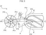
- FIG. 3 is a tool 41 used in the present embodiment.
- the tool 41 is a ball end mill having six cutting edges.
- the tool 41 is formed with three cutting edges 41a extending to the tip of the tool.
- the other three cutting edges 41b of the tool 41 are formed so as not to reach the tip of the tool. For this reason, when the tool rotates, a region where there are three effective edges comprised of edges contributing to cutting and a region where there are six effective edges are formed.
- Various techniques may be considered for dividing the regions, but in the case of a ball end mill, the regions can be expressed by an angle formed between the line passing through the center of a sphere at the part where the path drawn by the cutting edge of the tip of the tool becomes a sphere and the rotational axis C of the tool.
- an angle of 20° can be said to be the boundary of the region where there are three effective edges and the region where there are six effective edges.
- the number of the effective edges comprised of edges contributing to cutting when the tool 41 rotates is three in the region of an angle with respect to the rotational axis C of the tool of less than the angle of 20°.
- the machined surface of the workpiece 43 may be divided into a part machined by the region A of three effective edges and the part machined by the region B of six effective edges.
- the "machining condition" is in particular the feed speed and the objective is raising the feed speed.
- the contact region calculation unit 25 can find the angle formed by the rotational axis of the tool 41 and the normal of the machined surface of the workpiece and transfer information showing the region by this angle to the machining program generation unit 29.
- the machining program generation unit 29 refers to the storage unit 27. If the angle is 25° or more, it acquires the machining conditions for the region B of six effective edges while if is less than 25°, it acquires the machining conditions for the region A of three effective edges.
- the material of the workpiece 43 is die steel.
- the recommended feed speed of the ball end mill of FIG. 3 for die steel is 4800 mm/min with the region A of three effective edges, while is 9600 mm/min with the region B of six effective edges.
- the operator inputs the feed speed from the input unit 21 for each region of the tool and stores it in the storage unit 27.
- FIG. 4 shows an embodiment of three-axis machining in the case of generating a machining program performing contour machining on the workpiece 43 having slanted surfaces different in slant angles of the surfaces using X-, Y-, and Z-linear feed axes and not using the A and C rotational feed axes.
- the operator inputs information on the workpiece 43 having slanted surfaces, information on a tool 41, and information on the contour machining from the input unit 21.
- Contour machining is the process of making a tool move by an X-axis feed axis and a Y-axis feed axis and machining the workpiece 43 by a tool path drawing a contour.
- Machining is performed by a tool path corresponding to one turn of contour, then the tool is moved along a slanted surface downward by exactly the amount of pick feed, then machining is performed again so as to draw a contour at a height different in the X-axis and Y-axis.
- the routine performing machining by repeating this is called "contour machining".
- the tool path generation unit 23 generates a tool path in the input information.
- FIG. 4 shows parts of the tool path generated shown by the tool paths 101, 102, 103, and 104 of contours of one turn of contour machining for explanation. In actuality, the tool path generation unit 23 also generates tool paths not shown in FIG. 4 .
- the contact region calculation unit 25 calculates the region of the tool 41 contacting the workpiece 43. By calculation by the contact region calculation unit 25, machining by the region A of the three effective edges in the tool path 101 is found. Similarly, by calculation of the contact region calculation unit 25, machining by the region B of the six effective edges in the tool paths 102, 103, and 104 is found.
- the machining program generation unit 29 reads the feed speed from the storage unit 27, adds a command of the feed speed to the tool path, and generates a machining program.
- the tool path 101 is given a command for making the feed speed 4800 mm/min.
- the tool paths 102, 103, and 104 are given commands for making the feed speeds 9600 mm/min.
- the operator inputs the generated machining program into the NC device 71 and runs it so as to perform machining by the NC machine tool 51.
- This performs machining by a machining program generated by the machining program generation device 11 and given a suitable feed speed for each tool path, so NC machine tool 51 can efficiently perform machining in a short time without tool damage. Even if the NC machine tool 51 performs machining using a machining program with the feed speed set to 4800 mm/min for all paths, the machining time ends up becoming longer.
- the feed speed of the tool 41 will exceed the suitable value and the tool 41 can be chipped or the tool 41 will become shorter in lifetime.
- FIG. 5 shows an embodiment of five-axis machining in the case of generating a machining program for contour machining by five-axis machining of the X-, Y-, Z-, A-, and C-axes of a workpiece 43 having slanted surfaces of the same slant angles of the surfaces as in FIG. 4 .
- the processes by the tool path generation unit 23 and the contact region calculation unit 25 are similar to FIG. 4 .
- the machining condition judgment unit 31 judges if there isn't room for improvement of the machining conditions.
- the workpiece 43 is machined by the region of three effective edges, so machining conditions with a slow feed speed are selected. Therefore, the machining condition judgment unit 31 judges that there is room for raising the feed speed in the tool path 101.
- the tool posture change unit 33 changes the tool posture and finds the tool posture and position where machining is possible by the region B of six effective edges in the tool path 101 which the machining condition judgment unit 31 judged. Based on the tool posture and position where machining is possible by the region B of six effective edges found by the tool posture change unit 33, the tool path generation unit 23 generates a tool path with an inclined tool posture at the rotational feed axis A such as shown in FIG. 5 .
- the machining program generation unit 29 reading the newly generated tool path outputs a machining program slanting the tool posture and setting the feed speed to 9600 mm/min, since machining is performed by the region B of six effective edges even in the tool path 101. With this machining program, the NC machine tool 51 performs the machining by a fast feed speed by the region B of six effective edges even in the tool path 101, so there is no tool chipping and the machining time is shortened over the machining of FIG. 4 .
- the interference calculation unit 35 calculates whether portions of the tool other than the cutting edges or the main spindle and workpiece will interfere with each other before the tool posture change unit 33 sends out a change in tool posture and position to the tool path generation unit 23. In the example of FIG. 5 , there is no interference, so the tool posture is changed.
- the regions are divided into the two regions of the region A of three effective edges and the region B of six effective edges, but it is also possible to divide them into three regions including a region near the null point which matches the center of rotation of the tool and where the rotational speed of the cutting edges becomes zero besides the number of effective edges.
- the tool posture change unit 33 changes the tool posture so as to perform machining by the region A of three effective edges off from the null point when the region B of six effective edges cannot be selected due to interference.
Landscapes
- Engineering & Computer Science (AREA)
- Physics & Mathematics (AREA)
- Manufacturing & Machinery (AREA)
- General Physics & Mathematics (AREA)
- Automation & Control Theory (AREA)
- Human Computer Interaction (AREA)
- Mechanical Engineering (AREA)
- Geometry (AREA)
- General Engineering & Computer Science (AREA)
- Quality & Reliability (AREA)
- Numerical Control (AREA)
Claims (6)
- Dispositif de génération de programme d'usinage (11) générant un programme d'usinage usinant une pièce à usiner (43) en utilisant un outil (41) ayant une pluralité de bords de coupe, le dispositif comprenant :une unité de stockage (27) stockant une condition d'usinage pour chaque région de l'outil (41) définie sur la base du nombre de bords effectifs de chaque partie de l'outil (41) ;une unité de calcul de région de contact (25) calculant une région de l'outil (41) en contact avec la pièce à usiner (43) au moment de l'usinage à partir d'une forme de la pièce à usiner (43), d'une forme d'une partie de bord de l'outil (41) et d'un trajet d'outil, dans laquelle la région de l'outil (41) est établie sur la base du nombre de bords effectifs de chaque partie de l'outil (41) ; etune unité de génération de programme d'usinage (29) générant un programme d'usinage sur la base de la condition d'usinage stockée dans l'unité de stockage (27) et du trajet d'outil correspondant à la région de l'outil (41) en contact avec la pièce à usiner (43) calculée par l'unité de calcul de région de contact (25).
- Dispositif de génération de programme d'usinage (11) selon la revendication 1, dans lequel la condition d'usinage est une vitesse d'avance relative entre l'outil (41) et la pièce à usiner (43).
- Dispositif de génération de programme d'usinage (11) selon la revendication 1, dans lequel la condition d'usinage est une combinaison d'une vitesse d'avance relative entre l'outil (41) et la pièce à usiner (43) et d'une vitesse de rotation de l'outil (41).
- Dispositif de génération de programme d'usinage (11) selon la revendication 2, comprenant en outre une unité de changement de posture d'outil (33) changeant une posture relative entre l'outil (41) et la pièce à usiner (43) de sorte qu'une région de l'outil (41) où la vitesse d'avance augmente est en contact avec la pièce à usiner (43) dans une plage où l'outil (41) et la pièce à usiner (43) n'interfèrent pas.
- Dispositif de génération de programme d'usinage (11) selon la revendication 1, dans lequel l'unité de stockage (27) stocke la région de l'outil (41) comme une plage d'angle par rapport à un axe de rotation de l'outil (41).
- Procédé d'usinage pour usiner une pièce à usiner (43) en utilisant un outil (41) ayant une pluralité de bords de coupe, le procédé d'usinage comprenant les étapes suivantes :déterminer les conditions d'usinage pour chaque région de l'outil (41) définies sur la base du nombre de bords effectifs de chaque partie de l'outil (41) ;déterminer une région de l'outil (41) en contact avec la pièce à usiner (43) au moment de l'usinage à partir d'une forme de la pièce à usiner, une forme d'une partie de bord de l'outil (41), dans lequel la région de l'outil (41) est établie sur la base du nombre de bords effectifs de chaque partie de l'outil (41),et un trajet d'outil ; etusiner la pièce à usiner (43) en utilisant des conditions d'usinage correspondant à la région de l'outil (41) en contact avec la pièce à usiner (43).
Applications Claiming Priority (1)
| Application Number | Priority Date | Filing Date | Title |
|---|---|---|---|
| PCT/JP2016/071065 WO2018011990A1 (fr) | 2016-07-15 | 2016-07-15 | Dispositif de génération de programme d'usinage et procédé d'usinage |
Publications (3)
| Publication Number | Publication Date |
|---|---|
| EP3486032A1 EP3486032A1 (fr) | 2019-05-22 |
| EP3486032A4 EP3486032A4 (fr) | 2020-02-26 |
| EP3486032B1 true EP3486032B1 (fr) | 2022-03-16 |
Family
ID=60952446
Family Applications (1)
| Application Number | Title | Priority Date | Filing Date |
|---|---|---|---|
| EP16908890.3A Active EP3486032B1 (fr) | 2016-07-15 | 2016-07-15 | Dispositif de génération de programme d'usinage et procédé d'usinage |
Country Status (6)
| Country | Link |
|---|---|
| US (1) | US11577353B2 (fr) |
| EP (1) | EP3486032B1 (fr) |
| JP (1) | JP6563133B2 (fr) |
| KR (1) | KR20190013993A (fr) |
| CN (1) | CN109475993B (fr) |
| WO (1) | WO2018011990A1 (fr) |
Families Citing this family (4)
| Publication number | Priority date | Publication date | Assignee | Title |
|---|---|---|---|---|
| JP7112375B2 (ja) * | 2019-07-24 | 2022-08-03 | 株式会社日立製作所 | Ncプログラム生成システム及びncプログラム生成方法 |
| JP7299794B2 (ja) * | 2019-08-19 | 2023-06-28 | 株式会社牧野フライス製作所 | 加工条件を決定するための方法及び装置 |
| CN114902148B (zh) * | 2020-01-15 | 2023-08-22 | 三菱电机株式会社 | 数控装置及数控方法 |
| JPWO2022075223A1 (fr) * | 2020-10-05 | 2022-04-14 |
Family Cites Families (20)
| Publication number | Priority date | Publication date | Assignee | Title |
|---|---|---|---|---|
| JPS524934B1 (fr) | 1966-07-28 | 1977-02-08 | ||
| JPS5211485A (en) * | 1975-07-18 | 1977-01-28 | Shin Nippon Koki Kk | Feeding speed controller for machine tool |
| JPS6471647A (en) * | 1987-09-11 | 1989-03-16 | Mitsui Zosen Akishima Kenkyush | Method for cutting surf board |
| JPH08292808A (ja) * | 1995-04-24 | 1996-11-05 | Makino Milling Mach Co Ltd | ボールエンドミルによる切削加工方法および装置 |
| JP3506814B2 (ja) * | 1995-07-11 | 2004-03-15 | 東芝機械株式会社 | 数値制御装置 |
| JPH10151511A (ja) | 1996-11-25 | 1998-06-09 | Hitachi Tool Eng Co Ltd | 多刃ボールエンドミル |
| US6438445B1 (en) * | 1997-03-15 | 2002-08-20 | Makino Milling Machine Co., Ltd. | Machining processor |
| US6112133A (en) * | 1998-02-27 | 2000-08-29 | Imcs, Inc. | Visual system and method for generating a CNC program for machining parts with planar and curvilinear surfaces |
| JP2000084794A (ja) | 1998-09-14 | 2000-03-28 | Makino Milling Mach Co Ltd | 加工処理装置 |
| JP2001009672A (ja) | 1999-06-30 | 2001-01-16 | Toshiba Mach Co Ltd | 数値制御装置 |
| JP4480869B2 (ja) * | 2000-09-20 | 2010-06-16 | 東芝機械株式会社 | 数値制御装置 |
| JP2003256010A (ja) * | 2002-03-06 | 2003-09-10 | Mazda Motor Corp | 工作機械の制御方法及びその制御装置、並びに、その制御をコンピュータに実行させるプログラム及びそれを記録したコンピュータ読み取り可能な記録媒体 |
| KR100938728B1 (ko) * | 2002-07-24 | 2010-01-26 | 도시바 기카이 가부시키가이샤 | 공작기계와 공구 및 공구홀더 |
| JP2006035377A (ja) * | 2004-07-27 | 2006-02-09 | Toyota Motor Corp | ボールエンドミル |
| CN102528555B (zh) * | 2010-12-15 | 2014-11-05 | 上海工程技术大学 | 复杂曲面无干涉刀路的几何与力学集成优化信息处理方法 |
| US9459166B2 (en) | 2011-11-09 | 2016-10-04 | Komatsu Ltd. | Cutting resistance analysis device, cutting and machining device equipped with same, and cutting resistance analysis program |
| JP2013188831A (ja) * | 2012-03-14 | 2013-09-26 | Mitsubishi Electric Corp | 工作機械の制御装置およびそれを備えた工作機械 |
| EP2915625B1 (fr) * | 2012-10-30 | 2019-12-04 | Makino Milling Machine Co., Ltd. | Dispositif de commande de machine-outil et machine-outil |
| JP6033668B2 (ja) | 2012-12-25 | 2016-11-30 | 三菱日立パワーシステムズ株式会社 | Cam装置及び製品形状加工方法 |
| WO2016009502A1 (fr) * | 2014-07-16 | 2016-01-21 | ヤマザキマザック 株式会社 | Dispositif de commande de transformation par tournage et programme d'assistance de transformation par tournage |
-
2016
- 2016-07-15 KR KR1020187038102A patent/KR20190013993A/ko not_active Application Discontinuation
- 2016-07-15 WO PCT/JP2016/071065 patent/WO2018011990A1/fr unknown
- 2016-07-15 JP JP2018527367A patent/JP6563133B2/ja active Active
- 2016-07-15 EP EP16908890.3A patent/EP3486032B1/fr active Active
- 2016-07-15 US US16/318,065 patent/US11577353B2/en active Active
- 2016-07-15 CN CN201680087703.XA patent/CN109475993B/zh active Active
Also Published As
| Publication number | Publication date |
|---|---|
| JP6563133B2 (ja) | 2019-08-21 |
| WO2018011990A1 (fr) | 2018-01-18 |
| JPWO2018011990A1 (ja) | 2019-03-07 |
| EP3486032A4 (fr) | 2020-02-26 |
| KR20190013993A (ko) | 2019-02-11 |
| EP3486032A1 (fr) | 2019-05-22 |
| US11577353B2 (en) | 2023-02-14 |
| CN109475993B (zh) | 2021-06-11 |
| US20210276137A1 (en) | 2021-09-09 |
| CN109475993A (zh) | 2019-03-15 |
Similar Documents
| Publication | Publication Date | Title |
|---|---|---|
| US9785137B2 (en) | Five-axis flank milling system for machining curved surface and toolpath planning method thereof | |
| JP4943173B2 (ja) | スライドコア穴の加工方法およびスライドコア穴加工に用いる計測・補正システム | |
| EP3486032B1 (fr) | Dispositif de génération de programme d'usinage et procédé d'usinage | |
| US9244456B2 (en) | Tool path generation method and apparatus | |
| JP6684962B2 (ja) | 工具経路生成方法および装置 | |
| JP5818987B2 (ja) | 溝加工方法、工作機械の制御装置および工具経路生成装置 | |
| US10088824B2 (en) | Toolpath evaluation method, toolpath generation method, and toolpath generation device | |
| JP2005074569A (ja) | プログラム、コンピュータ装置、多軸加工機、ncプログラムの生成方法、ワークの加工方法 | |
| CN103713576A (zh) | 多轴铣削加工工件表面形貌建模方法 | |
| JP5911595B2 (ja) | 工作機械の制御装置および工作機械 | |
| WO2015114734A1 (fr) | Procédé de découpe et dispositif générateur de trajectoire d'outil | |
| JP5881850B2 (ja) | 工作機械の制御装置および工作機械 | |
| JP2002304203A (ja) | Nc工作機械および加工方法 | |
| CN114192811B (zh) | 车铣复合机床自动车削加工钛合金产品的方法 | |
| JP2008004124A (ja) | Nc加工装置 | |
| CN112083686A (zh) | 机床和机床的控制方法 | |
| JP4110571B2 (ja) | Nc加工装置 | |
| Monaro et al. | Evaluation of Dynamic Behavior of Machine Tools for Sculptured Surface Manufacturing | |
| JP5736667B2 (ja) | Ncプログラム作成装置 | |
| Inoue et al. | Rapid 5-axis control tool path Generation by Means of Interference-free Space Concept | |
| KR100397979B1 (ko) | 지그재그 공구경로 생성방법 | |
| JP2002160103A (ja) | 曲面加工方法及び曲面加工装置 | |
| Hadi | Ideal Selection of Circular Interpolation for CNC Turning Centers | |
| JP5645884B2 (ja) | 機械加工方法及び装置 | |
| JP2021039401A (ja) | 数値制御装置 |
Legal Events
| Date | Code | Title | Description |
|---|---|---|---|
| STAA | Information on the status of an ep patent application or granted ep patent |
Free format text: STATUS: THE INTERNATIONAL PUBLICATION HAS BEEN MADE |
|
| PUAI | Public reference made under article 153(3) epc to a published international application that has entered the european phase |
Free format text: ORIGINAL CODE: 0009012 |
|
| STAA | Information on the status of an ep patent application or granted ep patent |
Free format text: STATUS: REQUEST FOR EXAMINATION WAS MADE |
|
| 17P | Request for examination filed |
Effective date: 20190206 |
|
| AK | Designated contracting states |
Kind code of ref document: A1 Designated state(s): AL AT BE BG CH CY CZ DE DK EE ES FI FR GB GR HR HU IE IS IT LI LT LU LV MC MK MT NL NO PL PT RO RS SE SI SK SM TR |
|
| AX | Request for extension of the european patent |
Extension state: BA ME |
|
| DAV | Request for validation of the european patent (deleted) | ||
| DAX | Request for extension of the european patent (deleted) | ||
| REG | Reference to a national code |
Ref country code: DE Ref legal event code: R079 Ref document number: 602016070175 Country of ref document: DE Free format text: PREVIOUS MAIN CLASS: B23Q0015000000 Ipc: B23Q0015007000 |
|
| A4 | Supplementary search report drawn up and despatched |
Effective date: 20200129 |
|
| RIC1 | Information provided on ipc code assigned before grant |
Ipc: B23Q 15/007 20060101AFI20200123BHEP Ipc: G05B 19/416 20060101ALI20200123BHEP Ipc: G05B 19/4093 20060101ALI20200123BHEP |
|
| GRAP | Despatch of communication of intention to grant a patent |
Free format text: ORIGINAL CODE: EPIDOSNIGR1 |
|
| STAA | Information on the status of an ep patent application or granted ep patent |
Free format text: STATUS: GRANT OF PATENT IS INTENDED |
|
| INTG | Intention to grant announced |
Effective date: 20211110 |
|
| GRAS | Grant fee paid |
Free format text: ORIGINAL CODE: EPIDOSNIGR3 |
|
| GRAA | (expected) grant |
Free format text: ORIGINAL CODE: 0009210 |
|
| STAA | Information on the status of an ep patent application or granted ep patent |
Free format text: STATUS: THE PATENT HAS BEEN GRANTED |
|
| AK | Designated contracting states |
Kind code of ref document: B1 Designated state(s): AL AT BE BG CH CY CZ DE DK EE ES FI FR GB GR HR HU IE IS IT LI LT LU LV MC MK MT NL NO PL PT RO RS SE SI SK SM TR |
|
| REG | Reference to a national code |
Ref country code: GB Ref legal event code: FG4D |
|
| REG | Reference to a national code |
Ref country code: CH Ref legal event code: EP Ref country code: DE Ref legal event code: R096 Ref document number: 602016070175 Country of ref document: DE |
|
| REG | Reference to a national code |
Ref country code: IE Ref legal event code: FG4D |
|
| REG | Reference to a national code |
Ref country code: AT Ref legal event code: REF Ref document number: 1475545 Country of ref document: AT Kind code of ref document: T Effective date: 20220415 |
|
| REG | Reference to a national code |
Ref country code: LT Ref legal event code: MG9D |
|
| REG | Reference to a national code |
Ref country code: NL Ref legal event code: MP Effective date: 20220316 |
|
| PG25 | Lapsed in a contracting state [announced via postgrant information from national office to epo] |
Ref country code: SE Free format text: LAPSE BECAUSE OF FAILURE TO SUBMIT A TRANSLATION OF THE DESCRIPTION OR TO PAY THE FEE WITHIN THE PRESCRIBED TIME-LIMIT Effective date: 20220316 Ref country code: RS Free format text: LAPSE BECAUSE OF FAILURE TO SUBMIT A TRANSLATION OF THE DESCRIPTION OR TO PAY THE FEE WITHIN THE PRESCRIBED TIME-LIMIT Effective date: 20220316 Ref country code: NO Free format text: LAPSE BECAUSE OF FAILURE TO SUBMIT A TRANSLATION OF THE DESCRIPTION OR TO PAY THE FEE WITHIN THE PRESCRIBED TIME-LIMIT Effective date: 20220616 Ref country code: LT Free format text: LAPSE BECAUSE OF FAILURE TO SUBMIT A TRANSLATION OF THE DESCRIPTION OR TO PAY THE FEE WITHIN THE PRESCRIBED TIME-LIMIT Effective date: 20220316 Ref country code: HR Free format text: LAPSE BECAUSE OF FAILURE TO SUBMIT A TRANSLATION OF THE DESCRIPTION OR TO PAY THE FEE WITHIN THE PRESCRIBED TIME-LIMIT Effective date: 20220316 Ref country code: BG Free format text: LAPSE BECAUSE OF FAILURE TO SUBMIT A TRANSLATION OF THE DESCRIPTION OR TO PAY THE FEE WITHIN THE PRESCRIBED TIME-LIMIT Effective date: 20220616 |
|
| REG | Reference to a national code |
Ref country code: AT Ref legal event code: MK05 Ref document number: 1475545 Country of ref document: AT Kind code of ref document: T Effective date: 20220316 |
|
| PG25 | Lapsed in a contracting state [announced via postgrant information from national office to epo] |
Ref country code: LV Free format text: LAPSE BECAUSE OF FAILURE TO SUBMIT A TRANSLATION OF THE DESCRIPTION OR TO PAY THE FEE WITHIN THE PRESCRIBED TIME-LIMIT Effective date: 20220316 Ref country code: GR Free format text: LAPSE BECAUSE OF FAILURE TO SUBMIT A TRANSLATION OF THE DESCRIPTION OR TO PAY THE FEE WITHIN THE PRESCRIBED TIME-LIMIT Effective date: 20220617 Ref country code: FI Free format text: LAPSE BECAUSE OF FAILURE TO SUBMIT A TRANSLATION OF THE DESCRIPTION OR TO PAY THE FEE WITHIN THE PRESCRIBED TIME-LIMIT Effective date: 20220316 |
|
| PG25 | Lapsed in a contracting state [announced via postgrant information from national office to epo] |
Ref country code: NL Free format text: LAPSE BECAUSE OF FAILURE TO SUBMIT A TRANSLATION OF THE DESCRIPTION OR TO PAY THE FEE WITHIN THE PRESCRIBED TIME-LIMIT Effective date: 20220316 |
|
| PG25 | Lapsed in a contracting state [announced via postgrant information from national office to epo] |
Ref country code: SM Free format text: LAPSE BECAUSE OF FAILURE TO SUBMIT A TRANSLATION OF THE DESCRIPTION OR TO PAY THE FEE WITHIN THE PRESCRIBED TIME-LIMIT Effective date: 20220316 Ref country code: SK Free format text: LAPSE BECAUSE OF FAILURE TO SUBMIT A TRANSLATION OF THE DESCRIPTION OR TO PAY THE FEE WITHIN THE PRESCRIBED TIME-LIMIT Effective date: 20220316 Ref country code: RO Free format text: LAPSE BECAUSE OF FAILURE TO SUBMIT A TRANSLATION OF THE DESCRIPTION OR TO PAY THE FEE WITHIN THE PRESCRIBED TIME-LIMIT Effective date: 20220316 Ref country code: PT Free format text: LAPSE BECAUSE OF FAILURE TO SUBMIT A TRANSLATION OF THE DESCRIPTION OR TO PAY THE FEE WITHIN THE PRESCRIBED TIME-LIMIT Effective date: 20220718 Ref country code: ES Free format text: LAPSE BECAUSE OF FAILURE TO SUBMIT A TRANSLATION OF THE DESCRIPTION OR TO PAY THE FEE WITHIN THE PRESCRIBED TIME-LIMIT Effective date: 20220316 Ref country code: EE Free format text: LAPSE BECAUSE OF FAILURE TO SUBMIT A TRANSLATION OF THE DESCRIPTION OR TO PAY THE FEE WITHIN THE PRESCRIBED TIME-LIMIT Effective date: 20220316 Ref country code: CZ Free format text: LAPSE BECAUSE OF FAILURE TO SUBMIT A TRANSLATION OF THE DESCRIPTION OR TO PAY THE FEE WITHIN THE PRESCRIBED TIME-LIMIT Effective date: 20220316 Ref country code: AT Free format text: LAPSE BECAUSE OF FAILURE TO SUBMIT A TRANSLATION OF THE DESCRIPTION OR TO PAY THE FEE WITHIN THE PRESCRIBED TIME-LIMIT Effective date: 20220316 |
|
| PG25 | Lapsed in a contracting state [announced via postgrant information from national office to epo] |
Ref country code: PL Free format text: LAPSE BECAUSE OF FAILURE TO SUBMIT A TRANSLATION OF THE DESCRIPTION OR TO PAY THE FEE WITHIN THE PRESCRIBED TIME-LIMIT Effective date: 20220316 Ref country code: IS Free format text: LAPSE BECAUSE OF FAILURE TO SUBMIT A TRANSLATION OF THE DESCRIPTION OR TO PAY THE FEE WITHIN THE PRESCRIBED TIME-LIMIT Effective date: 20220716 Ref country code: AL Free format text: LAPSE BECAUSE OF FAILURE TO SUBMIT A TRANSLATION OF THE DESCRIPTION OR TO PAY THE FEE WITHIN THE PRESCRIBED TIME-LIMIT Effective date: 20220316 |
|
| REG | Reference to a national code |
Ref country code: DE Ref legal event code: R097 Ref document number: 602016070175 Country of ref document: DE |
|
| PLBE | No opposition filed within time limit |
Free format text: ORIGINAL CODE: 0009261 |
|
| STAA | Information on the status of an ep patent application or granted ep patent |
Free format text: STATUS: NO OPPOSITION FILED WITHIN TIME LIMIT |
|
| PG25 | Lapsed in a contracting state [announced via postgrant information from national office to epo] |
Ref country code: DK Free format text: LAPSE BECAUSE OF FAILURE TO SUBMIT A TRANSLATION OF THE DESCRIPTION OR TO PAY THE FEE WITHIN THE PRESCRIBED TIME-LIMIT Effective date: 20220316 |
|
| 26N | No opposition filed |
Effective date: 20221219 |
|
| PG25 | Lapsed in a contracting state [announced via postgrant information from national office to epo] |
Ref country code: SI Free format text: LAPSE BECAUSE OF FAILURE TO SUBMIT A TRANSLATION OF THE DESCRIPTION OR TO PAY THE FEE WITHIN THE PRESCRIBED TIME-LIMIT Effective date: 20220316 Ref country code: MC Free format text: LAPSE BECAUSE OF FAILURE TO SUBMIT A TRANSLATION OF THE DESCRIPTION OR TO PAY THE FEE WITHIN THE PRESCRIBED TIME-LIMIT Effective date: 20220316 |
|
| REG | Reference to a national code |
Ref country code: CH Ref legal event code: PL |
|
| REG | Reference to a national code |
Ref country code: BE Ref legal event code: MM Effective date: 20220731 |
|
| PG25 | Lapsed in a contracting state [announced via postgrant information from national office to epo] |
Ref country code: LU Free format text: LAPSE BECAUSE OF NON-PAYMENT OF DUE FEES Effective date: 20220715 Ref country code: LI Free format text: LAPSE BECAUSE OF NON-PAYMENT OF DUE FEES Effective date: 20220731 Ref country code: CH Free format text: LAPSE BECAUSE OF NON-PAYMENT OF DUE FEES Effective date: 20220731 |
|
| PG25 | Lapsed in a contracting state [announced via postgrant information from national office to epo] |
Ref country code: BE Free format text: LAPSE BECAUSE OF NON-PAYMENT OF DUE FEES Effective date: 20220731 |
|
| PG25 | Lapsed in a contracting state [announced via postgrant information from national office to epo] |
Ref country code: IE Free format text: LAPSE BECAUSE OF NON-PAYMENT OF DUE FEES Effective date: 20220715 |
|
| PGFP | Annual fee paid to national office [announced via postgrant information from national office to epo] |
Ref country code: IT Payment date: 20230710 Year of fee payment: 8 |
|
| PGFP | Annual fee paid to national office [announced via postgrant information from national office to epo] |
Ref country code: DE Payment date: 20230712 Year of fee payment: 8 |
|
| PG25 | Lapsed in a contracting state [announced via postgrant information from national office to epo] |
Ref country code: HU Free format text: LAPSE BECAUSE OF FAILURE TO SUBMIT A TRANSLATION OF THE DESCRIPTION OR TO PAY THE FEE WITHIN THE PRESCRIBED TIME-LIMIT; INVALID AB INITIO Effective date: 20160715 |
|
| PG25 | Lapsed in a contracting state [announced via postgrant information from national office to epo] |
Ref country code: MK Free format text: LAPSE BECAUSE OF FAILURE TO SUBMIT A TRANSLATION OF THE DESCRIPTION OR TO PAY THE FEE WITHIN THE PRESCRIBED TIME-LIMIT Effective date: 20220316 Ref country code: CY Free format text: LAPSE BECAUSE OF FAILURE TO SUBMIT A TRANSLATION OF THE DESCRIPTION OR TO PAY THE FEE WITHIN THE PRESCRIBED TIME-LIMIT Effective date: 20220316 |
|
| PGFP | Annual fee paid to national office [announced via postgrant information from national office to epo] |
Ref country code: GB Payment date: 20240530 Year of fee payment: 9 |
|
| PGFP | Annual fee paid to national office [announced via postgrant information from national office to epo] |
Ref country code: FR Payment date: 20240611 Year of fee payment: 9 |