EP3485773B1 - Vacuum cleaner nozzle - Google Patents
Vacuum cleaner nozzle Download PDFInfo
- Publication number
- EP3485773B1 EP3485773B1 EP17843778.6A EP17843778A EP3485773B1 EP 3485773 B1 EP3485773 B1 EP 3485773B1 EP 17843778 A EP17843778 A EP 17843778A EP 3485773 B1 EP3485773 B1 EP 3485773B1
- Authority
- EP
- European Patent Office
- Prior art keywords
- cleaning part
- rotation cleaning
- nozzle
- extension wall
- housing
- Prior art date
- Legal status (The legal status is an assumption and is not a legal conclusion. Google has not performed a legal analysis and makes no representation as to the accuracy of the status listed.)
- Active
Links
- 238000004140 cleaning Methods 0.000 claims description 117
- 239000000428 dust Substances 0.000 claims description 19
- 238000005192 partition Methods 0.000 claims description 19
- 238000010168 coupling process Methods 0.000 claims description 3
- 238000005859 coupling reaction Methods 0.000 claims description 3
- 230000008878 coupling Effects 0.000 claims description 2
- 239000000126 substance Substances 0.000 description 15
- 230000002093 peripheral effect Effects 0.000 description 12
- 210000004209 hair Anatomy 0.000 description 7
- 238000001816 cooling Methods 0.000 description 4
- 239000000463 material Substances 0.000 description 4
- 230000005611 electricity Effects 0.000 description 3
- 230000003068 static effect Effects 0.000 description 3
- RSMUVYRMZCOLBH-UHFFFAOYSA-N metsulfuron methyl Chemical compound COC(=O)C1=CC=CC=C1S(=O)(=O)NC(=O)NC1=NC(C)=NC(OC)=N1 RSMUVYRMZCOLBH-UHFFFAOYSA-N 0.000 description 2
- 229920000515 polycarbonate Polymers 0.000 description 2
- 239000004417 polycarbonate Substances 0.000 description 2
- 230000000694 effects Effects 0.000 description 1
- 239000004744 fabric Substances 0.000 description 1
- 238000009413 insulation Methods 0.000 description 1
- 230000035939 shock Effects 0.000 description 1
Images


Classifications
-
- A—HUMAN NECESSITIES
- A47—FURNITURE; DOMESTIC ARTICLES OR APPLIANCES; COFFEE MILLS; SPICE MILLS; SUCTION CLEANERS IN GENERAL
- A47L—DOMESTIC WASHING OR CLEANING; SUCTION CLEANERS IN GENERAL
- A47L9/00—Details or accessories of suction cleaners, e.g. mechanical means for controlling the suction or for effecting pulsating action; Storing devices specially adapted to suction cleaners or parts thereof; Carrying-vehicles specially adapted for suction cleaners
- A47L9/02—Nozzles
-
- A—HUMAN NECESSITIES
- A47—FURNITURE; DOMESTIC ARTICLES OR APPLIANCES; COFFEE MILLS; SPICE MILLS; SUCTION CLEANERS IN GENERAL
- A47L—DOMESTIC WASHING OR CLEANING; SUCTION CLEANERS IN GENERAL
- A47L5/00—Structural features of suction cleaners
- A47L5/12—Structural features of suction cleaners with power-driven air-pumps or air-compressors, e.g. driven by motor vehicle engine vacuum
- A47L5/22—Structural features of suction cleaners with power-driven air-pumps or air-compressors, e.g. driven by motor vehicle engine vacuum with rotary fans
- A47L5/24—Hand-supported suction cleaners
-
- A—HUMAN NECESSITIES
- A47—FURNITURE; DOMESTIC ARTICLES OR APPLIANCES; COFFEE MILLS; SPICE MILLS; SUCTION CLEANERS IN GENERAL
- A47L—DOMESTIC WASHING OR CLEANING; SUCTION CLEANERS IN GENERAL
- A47L9/00—Details or accessories of suction cleaners, e.g. mechanical means for controlling the suction or for effecting pulsating action; Storing devices specially adapted to suction cleaners or parts thereof; Carrying-vehicles specially adapted for suction cleaners
- A47L9/02—Nozzles
- A47L9/04—Nozzles with driven brushes or agitators
- A47L9/0405—Driving means for the brushes or agitators
- A47L9/0411—Driving means for the brushes or agitators driven by electric motor
-
- A—HUMAN NECESSITIES
- A47—FURNITURE; DOMESTIC ARTICLES OR APPLIANCES; COFFEE MILLS; SPICE MILLS; SUCTION CLEANERS IN GENERAL
- A47L—DOMESTIC WASHING OR CLEANING; SUCTION CLEANERS IN GENERAL
- A47L9/00—Details or accessories of suction cleaners, e.g. mechanical means for controlling the suction or for effecting pulsating action; Storing devices specially adapted to suction cleaners or parts thereof; Carrying-vehicles specially adapted for suction cleaners
- A47L9/02—Nozzles
- A47L9/04—Nozzles with driven brushes or agitators
- A47L9/0405—Driving means for the brushes or agitators
- A47L9/0416—Driving means for the brushes or agitators driven by fluid pressure, e.g. by means of an air turbine
-
- A—HUMAN NECESSITIES
- A47—FURNITURE; DOMESTIC ARTICLES OR APPLIANCES; COFFEE MILLS; SPICE MILLS; SUCTION CLEANERS IN GENERAL
- A47L—DOMESTIC WASHING OR CLEANING; SUCTION CLEANERS IN GENERAL
- A47L9/00—Details or accessories of suction cleaners, e.g. mechanical means for controlling the suction or for effecting pulsating action; Storing devices specially adapted to suction cleaners or parts thereof; Carrying-vehicles specially adapted for suction cleaners
- A47L9/02—Nozzles
- A47L9/04—Nozzles with driven brushes or agitators
- A47L9/0427—Gearing or transmission means therefor
-
- A—HUMAN NECESSITIES
- A47—FURNITURE; DOMESTIC ARTICLES OR APPLIANCES; COFFEE MILLS; SPICE MILLS; SUCTION CLEANERS IN GENERAL
- A47L—DOMESTIC WASHING OR CLEANING; SUCTION CLEANERS IN GENERAL
- A47L9/00—Details or accessories of suction cleaners, e.g. mechanical means for controlling the suction or for effecting pulsating action; Storing devices specially adapted to suction cleaners or parts thereof; Carrying-vehicles specially adapted for suction cleaners
- A47L9/02—Nozzles
- A47L9/04—Nozzles with driven brushes or agitators
- A47L9/0461—Dust-loosening tools, e.g. agitators, brushes
- A47L9/0466—Rotating tools
- A47L9/0477—Rolls
-
- A—HUMAN NECESSITIES
- A47—FURNITURE; DOMESTIC ARTICLES OR APPLIANCES; COFFEE MILLS; SPICE MILLS; SUCTION CLEANERS IN GENERAL
- A47L—DOMESTIC WASHING OR CLEANING; SUCTION CLEANERS IN GENERAL
- A47L9/00—Details or accessories of suction cleaners, e.g. mechanical means for controlling the suction or for effecting pulsating action; Storing devices specially adapted to suction cleaners or parts thereof; Carrying-vehicles specially adapted for suction cleaners
- A47L9/02—Nozzles
- A47L9/06—Nozzles with fixed, e.g. adjustably fixed brushes or the like
- A47L9/066—Nozzles with fixed, e.g. adjustably fixed brushes or the like with adjustably mounted brushes, combs, lips or pads; Height adjustment of nozzle or dust loosening tools
-
- A—HUMAN NECESSITIES
- A47—FURNITURE; DOMESTIC ARTICLES OR APPLIANCES; COFFEE MILLS; SPICE MILLS; SUCTION CLEANERS IN GENERAL
- A47L—DOMESTIC WASHING OR CLEANING; SUCTION CLEANERS IN GENERAL
- A47L9/00—Details or accessories of suction cleaners, e.g. mechanical means for controlling the suction or for effecting pulsating action; Storing devices specially adapted to suction cleaners or parts thereof; Carrying-vehicles specially adapted for suction cleaners
- A47L9/02—Nozzles
- A47L9/06—Nozzles with fixed, e.g. adjustably fixed brushes or the like
- A47L9/068—Nozzles combined with a different cleaning side, e.g. duplex nozzles or dual purpose nozzles
-
- A—HUMAN NECESSITIES
- A47—FURNITURE; DOMESTIC ARTICLES OR APPLIANCES; COFFEE MILLS; SPICE MILLS; SUCTION CLEANERS IN GENERAL
- A47L—DOMESTIC WASHING OR CLEANING; SUCTION CLEANERS IN GENERAL
- A47L9/00—Details or accessories of suction cleaners, e.g. mechanical means for controlling the suction or for effecting pulsating action; Storing devices specially adapted to suction cleaners or parts thereof; Carrying-vehicles specially adapted for suction cleaners
Definitions
- the present disclosure relates to a nozzle for a cleaner.
- a vacuum cleaner is a device that sucks air including dust using suction force generated by a suction motor mounted inside a cleaner body, and then filters the dust by a dust separator.
- a vacuum cleaner may be classified into a canister cleaner in which a suction nozzle configured to suck dust is provided separately from a body and is connected to the body by a connection device, an upright cleaner in which a suction nozzle is rotatably connected to a body and a handheld cleaner which is used in a state in which a user grips a body.
- a agitator that is a rotation brush to which a brush is attached is installed in a suction nozzle for a vacuum cleaner according to the related art, and cleaning is performed while dust in a floor or a carpet is scratched as the agitator is rotated.
- a cleaner head for a vacuum cleaner is disclosed in Korean Patent Application Publication No. 10-2014-0123091 as the prior art.
- the cleaner head includes a brush bar provided in a chamber and a motor configured to drive the brush bar.
- the motor rotates the brush bar, and the brush bar strikes a surface to be cleaned while the brush bar is rotated.
- the motor is inserted into a brush bar.
- KR 2016 0036625 A discloses a nozzle according to the preamble of claim 1.
- the present disclosure provides a nozzle for a cleaner, which may prevent a phenomenon in which hairs or threads are entangled in a rotation cleaning part, and may improve a cooling efficiency of a motor that is accommodated in the rotation cleaning part.
- a nozzle for a cleaner includes: a housing having a chamber formed in the housing and a front opening formed on a front side of the housing; a rotation cleaning part which is accommodated in the chamber and cleans a floor through a rotation operation, and of which at least a portion is exposed through the front opening; a partition member which is provided in the chamber to partition the chamber into two areas and of which at least a portion is in contact with the rotation cleaning part; a driving unit inserted into the rotation cleaning part to rotate the rotation cleaning part; and a connection tube connected to the housing and configured to transfer air introduced through the front opening to a dust container of the cleaner, wherein a lower passage formed below the rotation cleaning part and upper passages formed above the rotation cleaning part are provided in the chamber, and portions of the partition member are recessed to define the upper passages.
- a plurality of extension walls in contact with a rotation cleaning part are provided in an inner chamber of a nozzle housing, so that dust stacked on the rotation cleaning part may be brushed off, and hairs or threads may be prevented from being entangled in the rotation cleaning part.
- an upper passage formed above the rotation cleaning part is formed in the extension wall, so that a driving unit accommodated in the rotation cleaning part may be effectively cooled.
- a connection tube connecting the housing and a cleaner body to each other is hinge-coupled to the housing, so that the user may smoothly perform cleaning, and the hinge is provided between the front wheels and the rear wheel of the suction nozzle, so that the suction nozzle may be prevented from being overturned during the cleaning.
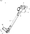
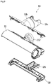
- FIG. 1 is a perspective view illustrating a vacuum cleaner according to an embodiment of the present disclosure.
- a vacuum cleaner 1 may include a cleaner body 10 having a suction motor (not illustrated) configured to generate suction force, a suction nozzle 110 configured to suck air including dust and an extension tube 17 connecting the cleaner body 10 and the suction nozzle 100 to each other.
- a suction motor not illustrated
- a suction nozzle 110 configured to suck air including dust
- an extension tube 17 connecting the cleaner body 10 and the suction nozzle 100 to each other.
- the suction nozzle 100 may be directly connected to the cleaner body 10 even without the extension tube 17.
- the cleaner body 10 may include a dust container 12 in which the dust separated from the air is stored. Although not illustrated, a dust separator may be provided inside the cleaner body 10.
- the dust introduced through the suction nozzle 100 is moved to the dust separator through the extension tube 17. Further, the dust separated from the dust separator may be stored in the dust container 12.
- a handle 13 to be gripped by a user may be provided in the cleaner body 10. The user may perform cleaning while gripping the handle 13.
- a battery (not illustrated) is provided in the cleaner body 10, and a battery accommodating part 15 in which the battery (not illustrated) is accommodated may be provided in the cleaner body 10.
- the battery accommodating part 15 may be provided below the handle 13.
- the battery (not illustrated) may be connected to the suction nozzle 100 to supply electric power to the suction nozzle 100.
- FIG. 2 is a perspective view illustrating a suction nozzle of FIG. 1
- FIG. 3 is a plan view illustrating the suction nozzle of FIG. 2
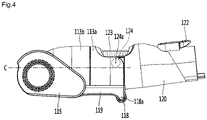
- FIG. 4 is a side view illustrating the suction nozzle of FIG. 1
- FIG. 5 is a front view illustrating the suction nozzle of FIG. 1
- FIG. 6 is a view illustrating a state in which a rotation cleaning part is separated from the suction nozzle of FIG. 5 .
- FIG. 7 is a bottom view illustrating the suction nozzle of FIG. 1
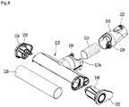
- FIG. 8 is an exploded perspective view illustrating the suction nozzle of FIG. 1
- FIG. 9 is an exploded perspective view illustrating a housing
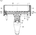
- FIG. 10 is a sectional view illustrating the suction nozzle taken along line I-I' of FIG. 7
- FIG. 11 is a sectional view taken along line II-II' of FIG. 7 .
- the suction nozzle 100 includes a housing 110, a connection tube 120 and a rotation cleaning part 130.
- the housing 110 includes a body 111 in which a chamber 112 is formed.
- a front opening 111a configured to suck air including polluted substances may be formed in the body 111. Air introduced through the front opening 111a by suction force generated by the cleaner body 10 may be moved to the connection tube 120 via the chamber 112.
- the front opening 111a extends in a left-right direction of the housing 110, and may extend to a front side of the housing 110 as well as a bottom surface of the housing 110. Accordingly, a suction area may be sufficiently ensured, so that a part of a floor, which is adjacent to a wall surface, may be uniformly cleaned.
- the housing 110 may further include an inner tube 1112 communicating with the front opening 111a. External air may be moved to an inner passage 1112a of the inner tube 1112 via the front opening 111a by suction force generated by the cleaner body 10.
- the housing 110 may further include a driving unit 140 configured to provide power for rotating the rotation cleaning part 130.
- the driving unit 140 may be inserted into one side of the rotation cleaning part 130 to transfer power to the rotation cleaning part 130.
- the driving unit 140 will be described in detail with reference to FIGS. 12 to 14 .
- the rotation cleaning part 130 may be accommodated in the chamber 112 of the body 111. At least a portion of the rotation cleaning part 130 may be exposed to the outside through the front opening 111a.
- the rotation cleaning part 130 may be rotated by driving force transferred through the driving unit 140 to rub against the floor so as to brush off the polluted substances.
- an outer peripheral surface of the rotation cleaning part 130 may be formed of fabric such as flannel or a felt material. Accordingly, when the rotation cleaning part 130 is rotated, foreign substances such as dust, which is stacked on the floor, may be effectively removed by the rotation cleaning part 130.
- the body 111 may cover at least a portion of an upper side of the rotation cleaning part 130. Further, an inner peripheral surface of the body 111 may be a curved shape to correspond to a shape of an outer peripheral surface of the rotation cleaning part 130. Accordingly, the body 111 may function to prevent the foreign substances, which is brushed off on the floor by rotating the rotation cleaning part 130, from being lifted up.
- the housing 110 may further include side covers 115 and 116 configured to cover side surfaces of the chamber 112.
- the side covers 115 and 116 may be located on opposite side surfaces of the rotation cleaning part 130.
- the side covers 115 and 116 include a first side cover 115 provided on one side of the rotation cleaning part 130 and a second side cover 116 provided on the other side of the rotation cleaning part 130.
- the driving unit 140 may be fixed to the first side cover 115.
- the suction nozzle 100 further includes a rotation support 150 provided in the second side cover 116 to rotatably support the rotation cleaning part 130.
- the rotation support 150 may be inserted into the other side of the rotation cleaning part 130 to rotatably support the rotation cleaning part 130.
- the rotation cleaning part 130 may be rotated in a counterclockwise direction with respect to the sectional view of FIG. 10 . That is, the rotation cleaning part 130 is rotated to push foreign substances at a contact point between the rotation cleaning part 130 and the floor toward the inner tube 1112. Thus, the foreign substances brushed off by the rotation cleaning part 130 are moved to the inner tube 1112 and are sucked to the inner tube 1112 by suction force.
- the rotation cleaning part 130 may be rotated rearward with respect to the contact point between the rotation cleaning part 130 and the floor to improve cleaning efficiency.
- a partition member 160 may be provided in the chamber 112.
- the partition member 160 may extend from an upper side to a lower side of the chamber 112 of the housing 110.
- the partition member 160 may be provided between the rotation cleaning part 130 and the inner tube 1112. Accordingly, the partition member 160 may partition the chamber 112 of the housing 110 into a first area 112a in which the rotation cleaning part 130 is provided and a second area 112b in which the inner tube 1112 is provided. As illustrated in FIG. 10 , the first area 112a may be provided in front of the chamber 112, and the second area 112b may be provided on a rear side of the chamber 112.
- the partition member 160 may include a first extension wall 161.
- the first extension wall 161 may extend to be in contact with at least a portion of the rotation cleaning part 130. Thus, when the rotation cleaning part 130 is rotated, the first extension wall 161 may remove the foreign substances attached to the rotation cleaning part 130 through friction between the first extension wall 161 and the rotation cleaning part 130.
- first extension wall 161 may extend along a rotation axis of the rotation cleaning part 130. That is, a contact point between the first extension wall 161 and the rotation cleaning part 130 may extend along the rotation axis of the rotation cleaning part 130.
- the first extension wall 161 may brush off the foreign substances attached to the rotation cleaning part 130 and may prevent the foreign substances on the floor from being introduced into the first area 112a of the chamber 112 as well.
- a phenomenon in which the foreign substances are discharged to a front side of the housing 110 through the front opening 111a by rotation of the rotation cleaning part 130 may be prevented by preventing the foreign substances from being introduced into the first area 112a of the chamber 112.
- the first extension wall 161 may prevent a phenomenon in which hairs or threads are entangled in the rotation cleaning part 130, by preventing hairs or threads attached to the rotation cleaning part 130 from being introduced into the first area 112a of the chamber 112. That is, the first extension wall 161 may perform an anti-tangle function.
- the partition member 160 may include a second extension wall 165.
- the second extension wall 165 may extend to be in contact with at least a portion of the rotation cleaning part 130, which is like the first extension wall 161.
- the second extension wall 165 may remove the foreign substances attached to the rotation cleaning part 130 through friction between the second extension wall 165 and the rotation cleaning part 130, which is like the first extension wall 161.
- the second extension wall 165 has the same function as that of the first extension wall 161. Further, because the foreign substances attached to the rotation cleaning part 130 may be brushed off only using the first extension wall 161 without the second extension wall 161, the second extension wall 165 may not be included in the housing 110.
- the second extension wall 165 may be arranged to be higher than the first extension wall 161.
- the second extension wall 165 may function to secondarily separate the foreign substances that have not been separated by the first extension wall 161 in the rotation cleaning part 130.
- a plurality of suction passages F1, F2 and F3 through which external air is moved to an inner tube of the body 111 are formed in the body 111 of the suction nozzle 100.
- the plurality of suction passages F1, F2 and F3 include a first lower passage F1 formed below the rotation cleaning part 130 and upper passages F2 and F3 formed above the rotation cleaning part 130.
- the lower passage F1 is formed below the rotation cleaning part 130.
- the lower passage F1 is connected to the inner passage 1112a sequentially via the front opening 111a, a lower side of the rotation cleaning part 130 and the second area 112b.
- the upper passages F2 and F3 are formed above the rotation cleaning part 130.
- the upper passages F2 and F3 are connected from the first area 112a via an upper side of the rotation cleaning part 130 and the second area 112b to the inner passage 1112a.
- the upper passages F2 and F3 may be joined to the lower passage F1 in the second area 112b.
- the upper passages F2 and F3 include a first upper passage F2 formed on one side of the housing 110 and a second upper passage F3 formed on the other side of the housing 110.
- the first upper passage F2 is arranged adjacent to the first side cover 115 and the second upper passage F3 may be arranged adjacent to the second side cover 116.
- a first lower groove 161a may be formed in the first extension wall 161 and a first upper groove 165a may be formed in the second extension wall 165.
- the first lower groove 161a is formed as an inner peripheral surface of the first extension wall 161, that is, a surface of the first extension wall 161, which is in contact with the rotation cleaning part 130, is recessed. Further, the first lower groove 161a may extend along a circumference direction of the rotation cleaning part 130.
- the first upper groove 165a is formed as an inner peripheral surface of the second extension wall 165, that is, a surface of the second extension wall 165, which is in contact with the rotation cleaning part 130, is recessed. Further, the first upper groove 165a may extend along the circumference direction of the rotation cleaning part 130.
- the first lower groove 161a and the first upper groove 165a are connected to each other and the first upper passage F2 is formed along the first lower groove 161a and the first upper groove 165a. Meanwhile, when the second extension wall 165 is not provided in the suction nozzle 100, the first upper passage F2 may be formed only using the first lower groove 161a.
- first lower groove 161a and the first upper groove 165a may be arranged to surround the driving unit 140.
- first upper passage F2 may be formed along a circumference of the driving unit 140 to surround at least a portion of the driving unit 140, and the driving unit 140 may be cooled by air flowing along the first upper passage F2.
- left-right directional widths A of the first lower groove 161a and the first upper groove 165a may be identical to each other as illustrated, the present disclosure is not limited thereto.
- the left-right directional widths A of the first lower groove 161a and the first upper groove 165a may have a predetermined size. When the left-right directional widths A are small, a flow rate of the air may be reduced or flow of the air may be blocked as a width of the first upper passage F2 is reduced. Thus, a cooling performance of the driving unit 140 may be slight.
- the left-right directional widths A may be formed to have an appropriate size, and may be formed to have a smaller width than a length of the driving unit 140.
- the left-right directional width A of the first upper groove 165a may be formed to have a width of 5-10 mm, but the present disclosure is not limited thereto.
- a spaced distance between an inner peripheral surface of the chamber 112 and an upper side of the rotation cleaning part 130 in the first upper passage F2 may be narrowed toward an inside of the chamber 112.
- a spaced distance between the inner peripheral surface of the chamber 112 and the upper side of the rotation cleaning part 130 may be formed to have d1 on a side of the first opening 111a, d2 in the first upper groove 165a and d3 in the first lower groove 161a.
- the d1 to d3 have smaller values as they go from d1 to d3 (d1>d2>d3).
- d1 may be 3mm
- d2 may be 2.7mm
- d3 may be 2mm.
- the flow rate of the air on the upper side of the rotation cleaning part 130 may be reduced as it may become more adjacent to the front opening 111a. Accordingly, a phenomenon in which the foreign substances are discharged to a front side by rotation of the rotation cleaning part 130 may be suppressed.
- a second lower groove 161b is formed in the first extension wall 161 and a second upper groove 165b is formed in the second extension wall 165.
- the second lower groove 161b is formed on the inner peripheral surface of the first extension wall 161, that is, the surface of the first extension wall 161, which is in contact with the rotation cleaning part 130, to be adjacent to the second side cover 116.
- the locations of the second lower groove 161b and the first lower groove 161a may be different from each other, and other components thereof are substantially identical to each other.
- the second upper groove 165b is formed on the inner peripheral surface of the second extension wall 165, that is, the surface of the second extension wall 165, which is in contact with the rotation cleaning part 130, to be adjacent to the second side cover 116.
- the second upper groove 165b and the second lower groove 161b are connected to each other and the second upper passage F3 is formed along the second lower groove 161b and the second upper groove 165b. Meanwhile, when the second extension wall 165 is not provided in the suction nozzle 100, the second upper passage F3 may be formed only using the second lower groove 161b.
- the second lower groove 161b and the second upper groove 165b may be arranged to surround the rotation support 150. Accordingly, the second upper passage F3 may be formed along a circumference of the rotation support 150, and the rotation support 150 may be cooled by air flowing along the second upper passage F3.
- left-right directional widths A of the second lower groove 161b and the second upper groove 165b may be identical to each other as illustrated, the present disclosure is not limited thereto.
- the left-right directional width A of the second lower groove 161b and the left-right directional width A of the second upper groove 165b may be formed to be identical to the left-right directional widths A of the first lower groove 161a and the first upper groove 165a.
- a spaced distance between the inner peripheral surface of the chamber 112 and the upper side of the rotation cleaning part 130 in the second upper passage F3 may be narrowed toward an inside of the chamber 112, which is like the first upper passage F2. Detailed description thereof will be omitted.
- the partition member 160 may further include a third extension wall 163 that is coupled to the first extension wall 161.
- the third extension wall 163 may be coupled to a rear surface of the first extension wall 161 to support the first extension wall 161.
- a portion of the third extension wall 163 may be exposed to the first area 112a of the chamber 112.
- the driving unit 140 may be effectively cooled
- the rotation support 150 may be effectively cooled.
- connection tube 120 may connect the housing 110 and the extension tube 17 (see FIG. 1 ). That is, one side of the connection tube 120 is connected to the housing 110, and the other side of the connection tube 120 is connected to the extension tube 17.
- a detachable button 122 configured to manipulate mechanical coupling with the extension tube 17 may be provided in the connection tube 120. The user may couple or separate the connection tube 120 and the extension tube 17 to or from each other by manipulating the detachable button 122.
- connection tube 120 may be rotatably connected to the housing 110.
- connection tube 120 may be hinge-coupled to a first connection member 113a to be vertically rotatable.
- Connection members 113a and 113b to be hinge-coupled to the connection tube 120 may be provided in the housing 110.
- the connection members 113a and 113b may be formed to surround the inner tube 1112.
- the connection members 113a and 113b may include a first connection member 113a and a second connection member 113b that are directly connected to the connection tube 120.
- One side of the second connection member 113b may be coupled to the first connection member 113a and the other side of the second connection member 113b may be coupled to the body 111.
- hinge holes 114 may be provided in the first connection member 113a and hinge shafts 124 inserted into the hinge holes 114 may be provided in the connection tube 120.
- hinge holes may be formed in the connection tube 120 and hinge shafts may be formed in the first connection member 113a.
- the hinge holes 114 and the hinges shafts 124 may be collectively named a "hinge part".
- a center 124a of each hinge shaft 124 may be arranged higher than a central axis C of the first connection member 113a. Accordingly, a rotational center of the connection tube 120 may be arranged higher than the central axis C of the first connection member 113a.
- the first connection member 113a may be rotatably connected to the second connection member 113b.
- the first connection member 113a may be rotated about a longitudinal axis.
- the suction nozzle 100 may further include an auxiliary hose 123 connecting the connection tube 120 and the inner tube 1112 of the housing 110. Accordingly, the air sucked to the housing 110 may be moved to the cleaner body 10 (see FIG. 1 ) via the auxiliary hose 123, the connection tube 120 and the extension tube 17 (see FIG. 1 ).
- the auxiliary hose 123 may be formed of a flexible material to enable rotation of the connection tube 120. Further, the first connection member 113a may have a shape surrounding at least a portion of the auxiliary hose 123 to protect the auxiliary hose 123.
- the suction nozzle 100 may further include front wheels 117a and 117b for moving during the cleaning.
- the front wheels 117a and 117b may be rotatably provided on the bottom surface of the housing 110. Further, the pair of front wheels 117a and 117b may be provided and may be arranged on a rear side of the front opening 111a.
- the suction nozzle 100 may further include a rear wheel 118.
- the rear wheel 118 may be rotatably provided on the bottom surface of the housing 110 and may be arranged further behind the front wheels 117a and 117b.
- the housing 110 may further include a support member 119 provided below the body 111.
- the support member 119 may support the body 111.
- the front wheels 117a and 117b may be rotatably coupled to the support member 119.
- An extension part 1192 extending rearward may be provided in the support member 119.
- the rear wheel 118 may be rotatably coupled to the extension part 1192.
- the extension part 1192 may support the first connection member 113a and the second connection member 113b on a lower side thereof.
- a rotary shaft 118a of the rear wheel 118 may be arranged further behind the center 124a of the hinge shaft 124. Accordingly, stability of the housing 110 is improved, so that the housing 110 may be prevented from being overturned during the cleaning.
- FIG. 12 is a view illustrating a state in which a first side cover of the suction nozzle is removed
- FIG. 13 is an exploded perspective view illustrating a driving unit
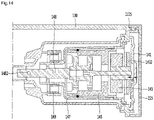
- FIG. 14 is a sectional view taken along a rotation axis of the rotation cleaning part.
- the driving unit 140 configured to rotate the rotation cleaning part 130 is coupled to the body 111 of the housing 110. At least a portion of the driving unit 140 may be inserted into one side of the rotation cleaning part 130.
- the driving unit 140 includes a motor 143 configured to generate driving force and a motor supporter 141.
- the motor 143 may include a BLDC motor.
- a printed circuit board (PCB) 1432 configured to control the motor 143 may be provided on one side of the motor 143.
- the motor 143 may be coupled to the motor supporter 141 by fastening members such as a bolt. Fastening holes 1434 for bolt-coupling with the motor supporter 141 may be formed in the motor 143.
- the driving unit 140 may further include a gear unit 145 configured to transfer power of the motor 143.
- the motor 143 may be inserted into the gear unit 145. To achieve this, a hollow hole may be formed inside the gear unit 145.
- the gear unit 145 may be bolt-coupled to the motor supporter 141, and to achieve this, fastening holes 1454 may be formed on one side of the gear unit 145.
- the gear unit 145, the motor 143 and the motor supporter 141 are integrally formed by fastening the gear unit 145 and the motor 143 to the motor supporter 141, so that vibrations generated while the motor 143 is operated may be reduced.
- the motor supporter 141 may be formed of, for example, a polycarbonate material.
- the polycarbonate material may have an excellent insulation property and an impact resistance.
- the motor supporter 141 may be resistant to external shocks and may prevent static electricity generated in the outside from being transferred to the motor 143.
- an inner peripheral surface of the motor supporter 141 is spaced apart from the PCB 1432 of the motor 143. Accordingly, even when the static electricity generated in the body 111 is transferred to the driving unit 140, the static electricity fails to arrive at the PCB 1432 of the motor 143 and may be naturally discharged, so that the PCB 1432 of the motor 143 may be protected.
- the motor supporter 141 is spaced apart from an inner peripheral surface of the first side cover 115. Accordingly, a cooling passage configured to cool the driving unit 140 may be ensured.
- the driving unit 140 may further include a cover 147 surrounding the gear unit 145.
- the cover 147 functions to protect the gear unit 145.
- the driving unit 140 further include a shaft 148 connected to the gear unit 145, and the shaft 148 is connected to the rotation cleaning part 130.
- the shaft 148 may transfer driving force transferred through the gear unit 145 to the rotation cleaning part 130. Accordingly, the rotation cleaning part 130 may be rotated.
- the driving unit 140 may further include bearings 149 installed in the cover 147.
- the bearings 149 may be connected to the shaft 148 to fix the shaft 148 to a predetermined location, and may rotate the shaft 148 while supporting a self-weight of the shaft 148 and a weight applied to the shaft 148. Accordingly, the shaft 148 may be smoothly rotated.
- the shaft 148 includes a fixing member 1482 fixed to the rotation cleaning part 130. Accordingly, the shaft 148 may be rotated together with the rotation cleaning part 130 while being fixed to the rotation cleaning part 130. Thus, the shaft 148 may rotate the rotation cleaning part 130 using driving force transferred by the motor 143 and the gear unit 145.
- a plurality of extension walls in contact with a rotation cleaning part are provided in an inner chamber of a nozzle housing, so that dust stacked on the rotation cleaning part may be brushed off, and hairs or threads may be prevented from being entangled in the rotation cleaning part.
- an upper passage formed above the rotation cleaning part is formed in the extension wall, so that a driving unit accommodated in the rotation cleaning part may be effectively cooled.
- a connection tube connecting the housing and a cleaner body to each other is hinge-coupled to the housing, so that the user may smoothly perform cleaning, and the hinge is provided between the front wheels and the rear wheel of the suction nozzle, so that the suction nozzle may be prevented from being overturned during the cleaning.
Landscapes
- Engineering & Computer Science (AREA)
- Mechanical Engineering (AREA)
- Nozzles For Electric Vacuum Cleaners (AREA)
Applications Claiming Priority (2)
| Application Number | Priority Date | Filing Date | Title |
|---|---|---|---|
| KR1020160108645A KR101903238B1 (ko) | 2016-08-25 | 2016-08-25 | 청소기의 노즐 |
| PCT/KR2017/005470 WO2018038358A1 (ko) | 2016-08-25 | 2017-05-25 | 청소기의 노즐 |
Publications (3)
| Publication Number | Publication Date |
|---|---|
| EP3485773A1 EP3485773A1 (en) | 2019-05-22 |
| EP3485773A4 EP3485773A4 (en) | 2019-07-03 |
| EP3485773B1 true EP3485773B1 (en) | 2022-05-11 |
Family
ID=61240926
Family Applications (1)
| Application Number | Title | Priority Date | Filing Date |
|---|---|---|---|
| EP17843778.6A Active EP3485773B1 (en) | 2016-08-25 | 2017-05-25 | Vacuum cleaner nozzle |
Country Status (8)
| Country | Link |
|---|---|
| US (1) | US10638901B2 (ko) |
| EP (1) | EP3485773B1 (ko) |
| JP (1) | JP6779362B2 (ko) |
| KR (1) | KR101903238B1 (ko) |
| CN (1) | CN207444893U (ko) |
| AU (1) | AU2017314586B9 (ko) |
| TW (1) | TWI732856B (ko) |
| WO (1) | WO2018038358A1 (ko) |
Families Citing this family (39)
| Publication number | Priority date | Publication date | Assignee | Title |
|---|---|---|---|---|
| US11617482B2 (en) | 2018-02-09 | 2023-04-04 | Sharkninja Operating Llc | Accessories for a surface treatment apparatus having a plurality of operational states and surface treatment apparatus configured to actuate the same |
| KR20190125911A (ko) * | 2018-04-30 | 2019-11-07 | 엘지전자 주식회사 | 청소기의 노즐 |
| WO2019212195A1 (ko) | 2018-04-30 | 2019-11-07 | 엘지전자 주식회사 | 청소기의 노즐 |
| CN115989981A (zh) | 2018-04-30 | 2023-04-21 | Lg电子株式会社 | 清洁器的吸嘴 |
| WO2019212177A1 (ko) | 2018-04-30 | 2019-11-07 | 엘지전자 주식회사 | 청소기의 노즐 |
| CN114504270B (zh) | 2018-04-30 | 2023-12-08 | Lg电子株式会社 | 用于清洁器的吸嘴 |
| CN116269038A (zh) | 2018-04-30 | 2023-06-23 | Lg电子株式会社 | 清洁器吸嘴 |
| KR20190125912A (ko) | 2018-04-30 | 2019-11-07 | 엘지전자 주식회사 | 청소기의 노즐 |
| KR102625905B1 (ko) | 2018-07-30 | 2024-01-18 | 엘지전자 주식회사 | 청소기의 노즐 |
| CN211985257U (zh) * | 2018-07-31 | 2020-11-24 | 尚科宁家运营有限公司 | 可重新配置的表面处理装置 |
| US11399675B2 (en) * | 2018-07-31 | 2022-08-02 | Sharkninja Operating Llc | Upright surface treatment apparatus having removable pod |
| USD912344S1 (en) * | 2018-08-29 | 2021-03-02 | Samsung Electronics Co., Ltd. | Cleaner |
| USD929685S1 (en) * | 2018-08-29 | 2021-08-31 | Samsung Electronics Co., Ltd. | Cleaner |
| USD929686S1 (en) * | 2018-08-29 | 2021-08-31 | Samsung Electronics Co., Ltd. | Cleaner |
| USD940413S1 (en) * | 2019-01-08 | 2022-01-04 | Suzhou CHO Electric Appliance Co., Ltd. | Vacuum cleaner |
| JP1644256S (ko) * | 2019-02-11 | 2019-10-28 | ||
| KR102128198B1 (ko) * | 2019-03-13 | 2020-06-29 | 임택순 | 스팀물걸레 진공청소기 |
| KR102172613B1 (ko) * | 2019-03-13 | 2020-11-02 | 임택순 | 스팀물걸레 진공청소기 |
| USD977770S1 (en) * | 2019-06-14 | 2023-02-07 | Sharkninja Operating Llc | Hand vacuum |
| JP1669073S (ko) * | 2019-07-31 | 2020-09-28 | ||
| JP1655533S (ko) * | 2019-08-01 | 2020-03-23 | ||
| KR102267512B1 (ko) * | 2019-12-03 | 2021-06-18 | 엘지전자 주식회사 | 진공 청소기 |
| KR102267510B1 (ko) * | 2019-12-03 | 2021-06-18 | 엘지전자 주식회사 | 진공 청소기 |
| KR20210090435A (ko) | 2020-01-10 | 2021-07-20 | 엘지전자 주식회사 | 진공 청소기 |
| KR20210105207A (ko) * | 2020-02-18 | 2021-08-26 | 엘지전자 주식회사 | 청소기 및 청소기의 제어방법 |
| KR102308662B1 (ko) * | 2020-07-23 | 2021-10-05 | 엘지전자 주식회사 | 노즐부 및 이를 포함하는 로봇 청소기 |
| US20230309768A1 (en) | 2020-08-27 | 2023-10-05 | Lg Electronics Inc. | Vacuum cleaner |
| KR20220027698A (ko) | 2020-08-27 | 2022-03-08 | 엘지전자 주식회사 | 진공청소기 |
| KR20220027703A (ko) | 2020-08-27 | 2022-03-08 | 엘지전자 주식회사 | 진공청소기 |
| TWD223040S (zh) * | 2020-08-28 | 2023-01-11 | 南韓商Lg電子股份有限公司 | 真空吸塵器主體 |
| USD959070S1 (en) * | 2020-09-02 | 2022-07-26 | Samsung Electronics Co., Ltd. | Vacuum cleaner |
| USD959071S1 (en) * | 2020-09-02 | 2022-07-26 | Samsung Electronics Co., Ltd. | Vacuum cleaner |
| KR102392550B1 (ko) | 2020-10-29 | 2022-04-28 | 오장근 | 흡입력 자동조절기능을 갖는 스틱형 무선진공청소기 |
| USD1020147S1 (en) * | 2020-11-02 | 2024-03-26 | Jiangsu Midea Cleaning Appliances Co., Ltd. | Combined vacuum cleaner and holder therefor |
| USD922010S1 (en) * | 2020-11-16 | 2021-06-08 | Dongguan Sogoode Computer System Co., Ltd | Vacuum cleaner |
| USD924503S1 (en) * | 2020-12-30 | 2021-07-06 | Fuzhou Huodan Electronic Technology Co., Ltd. | Cyclonic vacuum cleaner |
| USD957767S1 (en) * | 2021-03-31 | 2022-07-12 | Fornice Intelligent Technology Co., Ltd | Vacuum cleaner |
| US20220369883A1 (en) * | 2021-05-24 | 2022-11-24 | Zenith Technologies, Llc | Power sharing vacuum cleaner assembly |
| USD1012390S1 (en) * | 2023-07-11 | 2024-01-23 | Shenzhen Wenqu E-Commerce Co., Ltd. | Vacuum cleaner body |
Family Cites Families (20)
| Publication number | Priority date | Publication date | Assignee | Title |
|---|---|---|---|---|
| US4219902A (en) * | 1979-02-09 | 1980-09-02 | Oreck Corporation | Vacuum cleaning |
| JPS59130655A (ja) | 1983-01-17 | 1984-07-27 | Hitachi Ltd | 自動研削装置 |
| JPS59130655U (ja) * | 1983-02-23 | 1984-09-01 | 松下電器産業株式会社 | 電気掃除機の吸込具 |
| JP2986848B2 (ja) * | 1990-06-11 | 1999-12-06 | 株式会社日立製作所 | 電気掃除機の吸口 |
| KR100384980B1 (ko) * | 1998-04-03 | 2003-06-02 | 마츠시타 덴끼 산교 가부시키가이샤 | 회전 브러시 장치 및 이를 이용한 전기 기구 |
| JP3334701B2 (ja) * | 1999-03-02 | 2002-10-15 | 松下電器産業株式会社 | 電気掃除機用吸込具並びに電気掃除機 |
| JP3574000B2 (ja) | 1999-04-05 | 2004-10-06 | 三洋電機株式会社 | 電気掃除機 |
| JP2001095735A (ja) * | 1999-09-30 | 2001-04-10 | Matsushita Electric Ind Co Ltd | 電気掃除機 |
| JP3641618B2 (ja) * | 2002-05-02 | 2005-04-27 | 山崎産業株式会社 | 清掃器具 |
| KR101006013B1 (ko) * | 2008-12-26 | 2011-01-05 | 엘지전자 주식회사 | 진공 청소기의 노즐 |
| KR101054999B1 (ko) * | 2008-12-26 | 2011-08-05 | 엘지전자 주식회사 | 진공 청소기의 노즐 |
| GB2499213B (en) * | 2012-02-08 | 2016-10-19 | Dyson Technology Ltd | A cleaner-head for a vacuum cleaner |
| GB2516839B (en) * | 2013-07-31 | 2015-12-02 | Dyson Technology Ltd | Cleaner head for a vacuum cleaner |
| GB201313707D0 (en) * | 2013-07-31 | 2013-09-11 | Dyson Technology Ltd | Cleaner head for a vacuum cleaner |
| JP6178231B2 (ja) * | 2013-12-19 | 2017-08-09 | 日立アプライアンス株式会社 | 電気掃除機および吸込具 |
| GB201404917D0 (en) * | 2014-03-19 | 2014-04-30 | Dyson Technology Ltd | Cleaner head |
| GB2529820B (en) * | 2014-09-02 | 2016-10-26 | Dyson Technology Ltd | Cleaner head |
| DE102014115684A1 (de) * | 2014-10-29 | 2016-05-04 | Vorwerk & Co. Interholding Gesellschaft mit beschränkter Haftung | Saugeinheit für ein Haushaltsreinigungsgerät mit Parkfunktion |
| DE102014116589B4 (de) * | 2014-11-13 | 2019-02-07 | Vorwerk & Co. Interholding Gmbh | Saugdüse mit einer Stützrolle |
| KR101653481B1 (ko) * | 2015-01-16 | 2016-09-01 | 엘지전자 주식회사 | 진공 청소기 및 집진장치 |
-
2016
- 2016-08-25 KR KR1020160108645A patent/KR101903238B1/ko active IP Right Grant
-
2017
- 2017-04-21 CN CN201720424582.5U patent/CN207444893U/zh active Active
- 2017-04-25 TW TW106113809A patent/TWI732856B/zh active
- 2017-05-25 AU AU2017314586A patent/AU2017314586B9/en active Active
- 2017-05-25 JP JP2019504702A patent/JP6779362B2/ja active Active
- 2017-05-25 EP EP17843778.6A patent/EP3485773B1/en active Active
- 2017-05-25 WO PCT/KR2017/005470 patent/WO2018038358A1/ko unknown
- 2017-07-28 US US15/662,532 patent/US10638901B2/en active Active
Also Published As
| Publication number | Publication date |
|---|---|
| US10638901B2 (en) | 2020-05-05 |
| KR20180023401A (ko) | 2018-03-07 |
| AU2017314586B2 (en) | 2020-01-23 |
| US20180055313A1 (en) | 2018-03-01 |
| EP3485773A1 (en) | 2019-05-22 |
| JP2019521810A (ja) | 2019-08-08 |
| AU2017314586B9 (en) | 2020-02-06 |
| TW201806538A (zh) | 2018-03-01 |
| KR101903238B1 (ko) | 2018-10-01 |
| EP3485773A4 (en) | 2019-07-03 |
| TWI732856B (zh) | 2021-07-11 |
| AU2017314586A1 (en) | 2019-01-24 |
| JP6779362B2 (ja) | 2020-11-04 |
| WO2018038358A1 (ko) | 2018-03-01 |
| CN207444893U (zh) | 2018-06-05 |
Similar Documents
| Publication | Publication Date | Title |
|---|---|---|
| EP3485773B1 (en) | Vacuum cleaner nozzle | |
| EP3570716B1 (en) | Robot cleaner and maintenance device for the same | |
| EP3491989B1 (en) | Nozzle for cleaner | |
| EP2016882B1 (en) | Suction brush for vacuum cleaner | |
| KR102504105B1 (ko) | 진공 청소기 | |
| WO2005011461A1 (en) | Steam cleaner having vacuum cleaning function | |
| JP2012245179A (ja) | 電気掃除機および吸込具 | |
| JP2013070838A (ja) | 電気掃除機 | |
| JP2018075187A (ja) | 電気掃除機 | |
| KR101962160B1 (ko) | 청소기의 노즐 및 진공 청소기 | |
| JP2017006185A (ja) | 電気掃除機の吸込具及びこれを備えた電気掃除機 | |
| JP2015146959A (ja) | 電気掃除機 | |
| US8099814B1 (en) | Device for cleaning and scrubbing | |
| JP6552033B2 (ja) | 掃除機用吸込口及び電気掃除機 | |
| WO2020246026A1 (ja) | 掃除機ヘッドおよび電気掃除機 | |
| JP2013208161A (ja) | 電気掃除機 | |
| JP2015146960A (ja) | 電気掃除機 | |
| JP2016059639A (ja) | 掃除機本体および電気掃除機 | |
| JP2008194357A (ja) | 電気掃除機用吸込具およびこれを用いた電気掃除機 |
Legal Events
| Date | Code | Title | Description |
|---|---|---|---|
| STAA | Information on the status of an ep patent application or granted ep patent |
Free format text: STATUS: THE INTERNATIONAL PUBLICATION HAS BEEN MADE |
|
| PUAI | Public reference made under article 153(3) epc to a published international application that has entered the european phase |
Free format text: ORIGINAL CODE: 0009012 |
|
| STAA | Information on the status of an ep patent application or granted ep patent |
Free format text: STATUS: REQUEST FOR EXAMINATION WAS MADE |
|
| 17P | Request for examination filed |
Effective date: 20190215 |
|
| AK | Designated contracting states |
Kind code of ref document: A1 Designated state(s): AL AT BE BG CH CY CZ DE DK EE ES FI FR GB GR HR HU IE IS IT LI LT LU LV MC MK MT NL NO PL PT RO RS SE SI SK SM TR |
|
| AX | Request for extension of the european patent |
Extension state: BA ME |
|
| A4 | Supplementary search report drawn up and despatched |
Effective date: 20190604 |
|
| RIC1 | Information provided on ipc code assigned before grant |
Ipc: A47L 5/24 20060101AFI20190528BHEP Ipc: A47L 9/04 20060101ALI20190528BHEP |
|
| DAV | Request for validation of the european patent (deleted) | ||
| DAX | Request for extension of the european patent (deleted) | ||
| GRAP | Despatch of communication of intention to grant a patent |
Free format text: ORIGINAL CODE: EPIDOSNIGR1 |
|
| STAA | Information on the status of an ep patent application or granted ep patent |
Free format text: STATUS: GRANT OF PATENT IS INTENDED |
|
| INTG | Intention to grant announced |
Effective date: 20211208 |
|
| GRAJ | Information related to disapproval of communication of intention to grant by the applicant or resumption of examination proceedings by the epo deleted |
Free format text: ORIGINAL CODE: EPIDOSDIGR1 |
|
| STAA | Information on the status of an ep patent application or granted ep patent |
Free format text: STATUS: REQUEST FOR EXAMINATION WAS MADE |
|
| GRAS | Grant fee paid |
Free format text: ORIGINAL CODE: EPIDOSNIGR3 |
|
| STAA | Information on the status of an ep patent application or granted ep patent |
Free format text: STATUS: GRANT OF PATENT IS INTENDED |
|
| GRAP | Despatch of communication of intention to grant a patent |
Free format text: ORIGINAL CODE: EPIDOSNIGR1 |
|
| INTC | Intention to grant announced (deleted) | ||
| GRAA | (expected) grant |
Free format text: ORIGINAL CODE: 0009210 |
|
| STAA | Information on the status of an ep patent application or granted ep patent |
Free format text: STATUS: THE PATENT HAS BEEN GRANTED |
|
| INTG | Intention to grant announced |
Effective date: 20220330 |
|
| AK | Designated contracting states |
Kind code of ref document: B1 Designated state(s): AL AT BE BG CH CY CZ DE DK EE ES FI FR GB GR HR HU IE IS IT LI LT LU LV MC MK MT NL NO PL PT RO RS SE SI SK SM TR |
|
| REG | Reference to a national code |
Ref country code: GB Ref legal event code: FG4D |
|
| REG | Reference to a national code |
Ref country code: CH Ref legal event code: EP |
|
| REG | Reference to a national code |
Ref country code: AT Ref legal event code: REF Ref document number: 1490687 Country of ref document: AT Kind code of ref document: T Effective date: 20220515 |
|
| REG | Reference to a national code |
Ref country code: DE Ref legal event code: R096 Ref document number: 602017057441 Country of ref document: DE |
|
| REG | Reference to a national code |
Ref country code: IE Ref legal event code: FG4D |
|
| REG | Reference to a national code |
Ref country code: LT Ref legal event code: MG9D |
|
| REG | Reference to a national code |
Ref country code: NL Ref legal event code: MP Effective date: 20220511 |
|
| REG | Reference to a national code |
Ref country code: AT Ref legal event code: MK05 Ref document number: 1490687 Country of ref document: AT Kind code of ref document: T Effective date: 20220511 |
|
| PG25 | Lapsed in a contracting state [announced via postgrant information from national office to epo] |
Ref country code: SE Free format text: LAPSE BECAUSE OF FAILURE TO SUBMIT A TRANSLATION OF THE DESCRIPTION OR TO PAY THE FEE WITHIN THE PRESCRIBED TIME-LIMIT Effective date: 20220511 Ref country code: PT Free format text: LAPSE BECAUSE OF FAILURE TO SUBMIT A TRANSLATION OF THE DESCRIPTION OR TO PAY THE FEE WITHIN THE PRESCRIBED TIME-LIMIT Effective date: 20220912 Ref country code: NO Free format text: LAPSE BECAUSE OF FAILURE TO SUBMIT A TRANSLATION OF THE DESCRIPTION OR TO PAY THE FEE WITHIN THE PRESCRIBED TIME-LIMIT Effective date: 20220811 Ref country code: NL Free format text: LAPSE BECAUSE OF FAILURE TO SUBMIT A TRANSLATION OF THE DESCRIPTION OR TO PAY THE FEE WITHIN THE PRESCRIBED TIME-LIMIT Effective date: 20220511 Ref country code: LT Free format text: LAPSE BECAUSE OF FAILURE TO SUBMIT A TRANSLATION OF THE DESCRIPTION OR TO PAY THE FEE WITHIN THE PRESCRIBED TIME-LIMIT Effective date: 20220511 Ref country code: HR Free format text: LAPSE BECAUSE OF FAILURE TO SUBMIT A TRANSLATION OF THE DESCRIPTION OR TO PAY THE FEE WITHIN THE PRESCRIBED TIME-LIMIT Effective date: 20220511 Ref country code: GR Free format text: LAPSE BECAUSE OF FAILURE TO SUBMIT A TRANSLATION OF THE DESCRIPTION OR TO PAY THE FEE WITHIN THE PRESCRIBED TIME-LIMIT Effective date: 20220812 Ref country code: FI Free format text: LAPSE BECAUSE OF FAILURE TO SUBMIT A TRANSLATION OF THE DESCRIPTION OR TO PAY THE FEE WITHIN THE PRESCRIBED TIME-LIMIT Effective date: 20220511 Ref country code: ES Free format text: LAPSE BECAUSE OF FAILURE TO SUBMIT A TRANSLATION OF THE DESCRIPTION OR TO PAY THE FEE WITHIN THE PRESCRIBED TIME-LIMIT Effective date: 20220511 Ref country code: BG Free format text: LAPSE BECAUSE OF FAILURE TO SUBMIT A TRANSLATION OF THE DESCRIPTION OR TO PAY THE FEE WITHIN THE PRESCRIBED TIME-LIMIT Effective date: 20220811 Ref country code: AT Free format text: LAPSE BECAUSE OF FAILURE TO SUBMIT A TRANSLATION OF THE DESCRIPTION OR TO PAY THE FEE WITHIN THE PRESCRIBED TIME-LIMIT Effective date: 20220511 |
|
| PG25 | Lapsed in a contracting state [announced via postgrant information from national office to epo] |
Ref country code: RS Free format text: LAPSE BECAUSE OF FAILURE TO SUBMIT A TRANSLATION OF THE DESCRIPTION OR TO PAY THE FEE WITHIN THE PRESCRIBED TIME-LIMIT Effective date: 20220511 Ref country code: PL Free format text: LAPSE BECAUSE OF FAILURE TO SUBMIT A TRANSLATION OF THE DESCRIPTION OR TO PAY THE FEE WITHIN THE PRESCRIBED TIME-LIMIT Effective date: 20220511 Ref country code: LV Free format text: LAPSE BECAUSE OF FAILURE TO SUBMIT A TRANSLATION OF THE DESCRIPTION OR TO PAY THE FEE WITHIN THE PRESCRIBED TIME-LIMIT Effective date: 20220511 Ref country code: IS Free format text: LAPSE BECAUSE OF FAILURE TO SUBMIT A TRANSLATION OF THE DESCRIPTION OR TO PAY THE FEE WITHIN THE PRESCRIBED TIME-LIMIT Effective date: 20220911 |
|
| REG | Reference to a national code |
Ref country code: CH Ref legal event code: PL |
|
| REG | Reference to a national code |
Ref country code: BE Ref legal event code: MM Effective date: 20220531 |
|
| PG25 | Lapsed in a contracting state [announced via postgrant information from national office to epo] |
Ref country code: SM Free format text: LAPSE BECAUSE OF FAILURE TO SUBMIT A TRANSLATION OF THE DESCRIPTION OR TO PAY THE FEE WITHIN THE PRESCRIBED TIME-LIMIT Effective date: 20220511 Ref country code: SK Free format text: LAPSE BECAUSE OF FAILURE TO SUBMIT A TRANSLATION OF THE DESCRIPTION OR TO PAY THE FEE WITHIN THE PRESCRIBED TIME-LIMIT Effective date: 20220511 Ref country code: RO Free format text: LAPSE BECAUSE OF FAILURE TO SUBMIT A TRANSLATION OF THE DESCRIPTION OR TO PAY THE FEE WITHIN THE PRESCRIBED TIME-LIMIT Effective date: 20220511 Ref country code: LU Free format text: LAPSE BECAUSE OF NON-PAYMENT OF DUE FEES Effective date: 20220525 Ref country code: LI Free format text: LAPSE BECAUSE OF NON-PAYMENT OF DUE FEES Effective date: 20220531 Ref country code: EE Free format text: LAPSE BECAUSE OF FAILURE TO SUBMIT A TRANSLATION OF THE DESCRIPTION OR TO PAY THE FEE WITHIN THE PRESCRIBED TIME-LIMIT Effective date: 20220511 Ref country code: DK Free format text: LAPSE BECAUSE OF FAILURE TO SUBMIT A TRANSLATION OF THE DESCRIPTION OR TO PAY THE FEE WITHIN THE PRESCRIBED TIME-LIMIT Effective date: 20220511 Ref country code: CZ Free format text: LAPSE BECAUSE OF FAILURE TO SUBMIT A TRANSLATION OF THE DESCRIPTION OR TO PAY THE FEE WITHIN THE PRESCRIBED TIME-LIMIT Effective date: 20220511 Ref country code: CH Free format text: LAPSE BECAUSE OF NON-PAYMENT OF DUE FEES Effective date: 20220531 |
|
| REG | Reference to a national code |
Ref country code: DE Ref legal event code: R097 Ref document number: 602017057441 Country of ref document: DE |
|
| PG25 | Lapsed in a contracting state [announced via postgrant information from national office to epo] |
Ref country code: MC Free format text: LAPSE BECAUSE OF FAILURE TO SUBMIT A TRANSLATION OF THE DESCRIPTION OR TO PAY THE FEE WITHIN THE PRESCRIBED TIME-LIMIT Effective date: 20220511 |
|
| PLBE | No opposition filed within time limit |
Free format text: ORIGINAL CODE: 0009261 |
|
| STAA | Information on the status of an ep patent application or granted ep patent |
Free format text: STATUS: NO OPPOSITION FILED WITHIN TIME LIMIT |
|
| PG25 | Lapsed in a contracting state [announced via postgrant information from national office to epo] |
Ref country code: AL Free format text: LAPSE BECAUSE OF FAILURE TO SUBMIT A TRANSLATION OF THE DESCRIPTION OR TO PAY THE FEE WITHIN THE PRESCRIBED TIME-LIMIT Effective date: 20220511 |
|
| 26N | No opposition filed |
Effective date: 20230214 |
|
| PG25 | Lapsed in a contracting state [announced via postgrant information from national office to epo] |
Ref country code: IE Free format text: LAPSE BECAUSE OF NON-PAYMENT OF DUE FEES Effective date: 20220525 |
|
| PG25 | Lapsed in a contracting state [announced via postgrant information from national office to epo] |
Ref country code: SI Free format text: LAPSE BECAUSE OF FAILURE TO SUBMIT A TRANSLATION OF THE DESCRIPTION OR TO PAY THE FEE WITHIN THE PRESCRIBED TIME-LIMIT Effective date: 20220511 Ref country code: BE Free format text: LAPSE BECAUSE OF NON-PAYMENT OF DUE FEES Effective date: 20220531 |
|
| P01 | Opt-out of the competence of the unified patent court (upc) registered |
Effective date: 20230527 |
|
| PGFP | Annual fee paid to national office [announced via postgrant information from national office to epo] |
Ref country code: IT Payment date: 20230406 Year of fee payment: 7 Ref country code: FR Payment date: 20230405 Year of fee payment: 7 Ref country code: DE Payment date: 20230405 Year of fee payment: 7 |
|
| PGFP | Annual fee paid to national office [announced via postgrant information from national office to epo] |
Ref country code: GB Payment date: 20230405 Year of fee payment: 7 |
|
| PG25 | Lapsed in a contracting state [announced via postgrant information from national office to epo] |
Ref country code: HU Free format text: LAPSE BECAUSE OF FAILURE TO SUBMIT A TRANSLATION OF THE DESCRIPTION OR TO PAY THE FEE WITHIN THE PRESCRIBED TIME-LIMIT; INVALID AB INITIO Effective date: 20170525 |
|
| PG25 | Lapsed in a contracting state [announced via postgrant information from national office to epo] |
Ref country code: MK Free format text: LAPSE BECAUSE OF FAILURE TO SUBMIT A TRANSLATION OF THE DESCRIPTION OR TO PAY THE FEE WITHIN THE PRESCRIBED TIME-LIMIT Effective date: 20220511 Ref country code: CY Free format text: LAPSE BECAUSE OF FAILURE TO SUBMIT A TRANSLATION OF THE DESCRIPTION OR TO PAY THE FEE WITHIN THE PRESCRIBED TIME-LIMIT Effective date: 20220511 |