EP3485271B1 - Verfahren und systeme zur messung und inspektion von rohrförmigen waren - Google Patents
Verfahren und systeme zur messung und inspektion von rohrförmigen waren Download PDFInfo
- Publication number
- EP3485271B1 EP3485271B1 EP17828403.0A EP17828403A EP3485271B1 EP 3485271 B1 EP3485271 B1 EP 3485271B1 EP 17828403 A EP17828403 A EP 17828403A EP 3485271 B1 EP3485271 B1 EP 3485271B1
- Authority
- EP
- European Patent Office
- Prior art keywords
- tubular good
- section
- unit
- longitudinal axis
- tubular
- Prior art date
- Legal status (The legal status is an assumption and is not a legal conclusion. Google has not performed a legal analysis and makes no representation as to the accuracy of the status listed.)
- Active
Links
Images


Classifications
-
- G—PHYSICS
- G01—MEASURING; TESTING
- G01B—MEASURING LENGTH, THICKNESS OR SIMILAR LINEAR DIMENSIONS; MEASURING ANGLES; MEASURING AREAS; MEASURING IRREGULARITIES OF SURFACES OR CONTOURS
- G01B11/00—Measuring arrangements characterised by the use of optical techniques
- G01B11/08—Measuring arrangements characterised by the use of optical techniques for measuring diameters
- G01B11/10—Measuring arrangements characterised by the use of optical techniques for measuring diameters of objects while moving
- G01B11/105—Measuring arrangements characterised by the use of optical techniques for measuring diameters of objects while moving using photoelectric detection means
-
- G—PHYSICS
- G01—MEASURING; TESTING
- G01B—MEASURING LENGTH, THICKNESS OR SIMILAR LINEAR DIMENSIONS; MEASURING ANGLES; MEASURING AREAS; MEASURING IRREGULARITIES OF SURFACES OR CONTOURS
- G01B11/00—Measuring arrangements characterised by the use of optical techniques
- G01B11/08—Measuring arrangements characterised by the use of optical techniques for measuring diameters
- G01B11/12—Measuring arrangements characterised by the use of optical techniques for measuring diameters internal diameters
Definitions
- Such data arrays of wall thickness and associated outer diameter measurements produce pseudo (virtual) three-dimensional representations of short (typically one-half inch) sections of a pipe or other tubular good at discrete longitudinal positions.
- Each adjacent ring section is characterized by its own independent, discrete set of three-dimensional data, and the only relative measure between adjacent discrete sections is the longitudinal distance between them.
- data of this sort is graphically displayed, with all discrete ring sections connected, a perfectly straight three-dimensional representation of a tubular good is produced. In other words, the geometric centerlines of the discrete ring sections align themselves along the longitudinal z-axis and do not deviate radially in the transverse x-y plane.
- Manufactured pipes are never perfectly straight and have sections that are radially offset in the transverse x-y plane.
- off-axis hooks end area deviations
- sweeps full length bows
- helical out-of-straightness patterns are often observed.
- the tubular good dimensional measurement systems in use today do not address the off-axis relational data that is needed to produce true three-dimensional representations of manufactured pipes, which exhibit complex off-axis straightness imperfections.
- the cost to inspect pipe is a function of several factors, including the cost of the measurement apparatus, the cost of the systems used to store and process the generated data arrays for each pipe, the time required to complete the full inspection process, the manpower and training required to operate the systems, and the cost to maintain the measurement system and the data storage and processing system.
- Typical retail prices for inspecting a small quantity of pipe range from $900 to $1,200 per joint of oil country tubular casing. Large quantity retail prices are approximately $300 per joint.
- ultrasonic inspection facilities with large transducer arrays are typically employed to measure oil country tubular goods, which significantly increases maintenance costs. Inspection costs can significantly increase the cost of tubular goods.
- wall thickness measurements of a tubular good along an entire length and circumference of the tubular good are obtained by calculations involving the outside and inside diameter dimensions which are measured by laser or other light measurement systems.
- Discrete ring-shaped sections of a tubular good can be identified. For each such discrete section, at least one measurement of an outer diameter of an outside surface of the discrete section, and at least one measurement of an inner diameter of an inside surface of the discrete section are obtained.
- a geometric center coordinate for each discrete section of the tubular good is obtained. The measurements defining the outside surface, inside surface, and geometric center in association with the longitudinal position of each discrete section are recorded.
- Each measurement of the outer and inner diameters and associated geometric center can represent a small fraction of the total respective diameters and geometric centers of the tubular good in three-dimensional space.
- a number of such measurements can be utilized to create a virtual three-dimensional form of the tubular good including straightness anomalies, whether longitudinal or helical in nature.
- the outer diameters, inner diameters, and/or geometric centers of the discrete sections of the tubular good can be visually represented or displayed so that anomalies of interest, including straightness anomalies, for example, may be readily detected.
- the outer diameters, inner diameters, and/or geometric centers of the discrete sections can be graphically represented.
- different shades or colors may represent different values of the outer diameters, inner diameters, and/or geometric centers of the discrete sections. For example, a darker shade can represent a greater inner diameter and a lighter shade may represent a smaller inner diameter.
- the recorded values of the outer diameters, inner diameters, and/or geometric centers of the discrete sections of the tubular good may be processed to obtain a virtual wall thickness of the tubular good along its length and/or predict effects of stressors on the tubular good such as, for example, stressors that may be encountered when the tubular good is in service.
- the present disclosure relates to non-destructive measurement of tubular goods.
- non-destructive methods and systems are used to determine outside diameters, inside diameters, geometric centers, and/or wall thicknesses of steel pipe or other tubular goods by use of laser or other light measurement apparatus.
- the present disclosure relates to an improved method of collecting, storing, displaying, and otherwise utilizing information derived from laser or other light measurement systems to capture dimensional data and calculate and store wall thickness data for a tubular good.
- the present disclosure relates to the use of laser or other light measurement systems to acquire incremental data representing small, discrete sections of the outside and inside tubular surfaces in association with three-dimensional positional data pertaining to each small, discrete section, so that the wall of a tubular, or substantiality tubular, structure, or portions thereof, can be displayed, imaged, examined, and/or utilized in simulative/comparative programs as a three-dimensional object.
- a method for generating a virtual three-dimensional profile of a tubular, or at least substantially tubular, structure, or region(s) thereof includes selecting diametric sections of the tubular structure at discrete positions along a predetermined length of the tubular structure.
- the predetermined length can be the entire length of the tubular structure.
- the method further includes determining, for each section, a plurality of outer diameters of an outside surface of the section, and a plurality of inner diameters of an inside surface of the section. The number of inner diameters and outer diameters measured represents a desired resolution of the selected section.
- the method further includes determining a geometric center coordinate for each of the sections.
- the method further includes employing the determined inner diameters, outer diameters, and corresponding geometric center coordinates to create a virtual three-dimensional profile of the tubular good including, for example, surface anomalies.
- the tubular structure 8 can, for example, be an oil country tubular good such as a pipe, as illustrated in FIGS. 2-6 .
- the system 4 includes a circuit 10.
- the circuit 10 includes a controller 12, an outer unit 14, a middle unit 15, and an inner unit 16.
- the controller 12 may comprise one or more processors 18 (e.g., microprocessor, microcontroller) coupled to at least one memory circuit 20.
- At least one memory circuit 20 stores machine executable instructions that, when executed by the processor 18, cause the processor 18 to perform one or more functions.
- the at least one memory circuit 20 stores machine executable instructions that, when executed by the processor 18, cause the processor 18 to generate a virtual three-dimensional profile of a tubular structure 8 based on input data from the inner unit 16, the middle unit 15, and the outer unit 14.
- the steps performed by the processor 18 may include selecting discrete diametric sections of the tubular structure 8 at discrete positions along a predetermined length of the tubular structure 8.
- the predetermined length can be the entire length of the tubular structure 8 or a portion thereof.
- the steps performed by the processor 18 may further include determining, for each diametric section, a plurality of outer diameters of an outside surface of the section, and a plurality of inner diameters of an inside surface of the section. The number of inner diameters and outer diameters determined for a discrete section represent a desired resolution of the selected section.
- the steps performed by the processor 18 may further include determining geometric center coordinates for each of the sections and using wall measurements provided by the middle unit 15 to calibrate the orientation and position of the outer diameters with respect to the inner diameters and to correct for any errors of frictional slippage of the tubular structure 8 as it moves through the outer unit 14, middle unit 15, and inner unit 16.
- the method further includes employing the determined inner diameters, outer diameters, and corresponding geometric center coordinates of the multiple analyzed sections of the tubular structure 8 to create a virtual three-dimensional profile of the tubular structure 8.
- one or more of the various steps described herein can be performed by a finite state machine comprising either a combinational logic circuit or a sequential logic circuit, wherein either the combinational logic circuit or the sequential logic circuit is coupled to at least one memory circuit. At least one memory circuit stores a current state of the finite state machine.
- the combinational or sequential logic circuit is configured to cause the finite state machine to perform the steps.
- the sequential logic circuit may be synchronous or asynchronous.
- one or more of the various steps described herein can be performed by a circuit that includes a combination of the processor 18 and the finite state machine, for example.
- the controller 12 and/or other controllers of the present disclosure may be implemented using integrated and/or discrete hardware elements, software elements, and/or a combination of both.
- integrated hardware elements may include processors, microprocessors, microcontrollers, integrated circuits, ASICs, PLDs, DSPs, FPGAs, logic gates, registers, semiconductor devices, chips, microchips, chip sets, microcontrollers, SoC, and/or SIP.
- discrete hardware elements may include circuits and/or circuit elements such as logic gates, field effect transistors, bipolar transistors, resistors, capacitors, inductors, and/or relays.
- the controller 12 may include a hybrid circuit comprising discrete and integrated circuit elements or components on one or more substrates, for example.
- the processor 18 may be any one of a number of single or multi-core processors known in the art.
- the memory circuit 20 may comprise volatile and non-volatile storage media.
- the processor 18 may include an instruction processing unit and an arithmetic unit.
- the instruction processing unit may be configured to receive instructions from memory circuit 20.
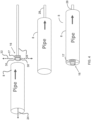
- the outer unit 14 includes a rotatable drum 22 which can be configured to rotate about a longitudinal axis 24.
- the rotatable drum 22 may have a cylindrical shape and a fixed outer shell 23, as illustrated in FIGS. 2-3 .
- One or more laser units can be positioned on an inner wall of the rotatable drum 22.
- laser units 26, 26' are disposed on opposite sides of an inner wall or face of the rotatable drum 22.
- the laser units 26 and 26' are circumferentially disposed on the inner wall or face of the rotatable drum 22 at angles of 90° and 270°.
- the laser units 26, 26' may be circumferentially spaced apart by about 180°on the inner wall or face of the rotatable drum 22.
- the laser units 26 and 26' may be oriented toward one another. Additional sets of laser measurement units may be disposed on the inner wall or face of the rotatable drum 22 spaced apart by approximately 180°.
- the laser units 26, 26' are configured to communicate input data to the controller 12 based on measurements taken by the laser units 26, 26' and additional sets of laser units, if present.
- the controller 12 may employ the input data from the laser units 26, 26' to determine outer diameter values of the outside surface of tubular structure 8 that are based on the measurements.
- the measurements comprise gap distances that are simultaneously measured between the laser units 26, 26' and the outside surface of the tubular structure 8 as the tubular structure passes through the rotatable drum 22. The same can be said of any additional sets of non-interfering laser units that may be employed on the inner wall or face of the rotatable drum 22.
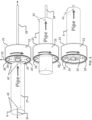
- the inner unit 16 includes a mounting member 28 in the form of a stationary mandrel, for example, extending along the longitudinal axis 24.
- Two laser units 30, 30' are affixed to a rotational motor 17 which is attached to and extends from the mounting member 28.
- the laser units 30, 30' are pointing in opposite directions along an axis 32 that is perpendicular, or at least substantially perpendicular, to the longitudinal axis, and the laser units 30 and 30' are rotating about the longitudinal axis 24.
- Additional sets of laser measurement units may be affixed to the rotational motor 17 at approximately 180° apart.
- an inner unit 16' can utilize a power driven trolley car 43 that pulls itself and any connecting cables 44 through the interior of the tubular structure 8.
- the laser units 30, 30' are connected to a rotary motor 17 which in turn is attached to the front of trolley car 43. Additional sets of laser measurement units 30, 30' may be affixed to the rotational motor 17 at approximately 180° apart.
- outer unit 14 and inner unit 16 can be operated at different stations, in at least one embodiment, illustrated in FIG. 6 , the outer unit 14 and the inner unit 16 operate at the same station such that the laser units 26, 26', 30, 30' are aligned with one another along the axis 32.
- the mounting member 28 is configured to be centered on the inside of the tubular structure 8 with centering guide flukes or rollers that make contact with the inside wall of the tubular structure 8.
- the laser units 30, 30' are configured to communicate input data to the controller 12 based on measurements taken by the laser units 30, 30'.
- the controller 12 may employ the input data from the laser units 30, 30' to determine inner diameter values of the inside surface of the tubular structure 8 that are based on the measurements taken by the laser units 30, 30'.
- the measurements comprise gap distances that are simultaneously measured between the laser units 30, 30' and the inside surface of the tubular structure 8.
- a tubular structure 8 is centered around the longitudinal axis 24, as illustrated in FIG. 6 .
- the tubular structure 8 is translated along the longitudinal axis 24 toward the inner unit 16 and outer unit 14 at separate operating stations as illustrated in FIGS. 2-5 or in some combined operating station such as illustrated in FIG. 6 .
- the tubular structure 8 is translated so as to pass between the inner unit 16 and/or outer unit 14.
- the tubular structure 8 is configured to move through the outer unit 14 and around the inner unit 16 at separate operating stations or in a single combined station.
- the laser units 26, 26', 30, 30' continuously take their respective measurements of the outside and inside surfaces of the tubular structure 8.
- the middle unit 15 provides at least two direct wall measurements at approximately 90° apart and at each end of the tubular structure 8 including the longitudinal separation distance 27, as illustrated in FIGS. 2 , 5 , and 6 .
- the middle unit 15 provides continuous or intermittent wall measurements in two or more lines at approximately 90° apart along the length of the tubular structure 8 as it advances through the outer unit 14.
- at least two single trace wall measurement devices such as, for example, ultrasonic testing (UT) transducers or other suitable wall sensors are employed.
- the wall measurement data provided by the middle unit 15 is also used to synchronize the outer diameter and inner diameter data provided by outer unit 14 and inner unit 16 such that a suitably accurate three dimensional relationship of the tubular structure 8 is established and can result in the output of a virtual three-dimensional display or data base of the tubular structure 8 by processor 18.
- the user input device 6 can also be employed to enter identification information corresponding to the particular tubular structure 8 to be inspected by the inspection system 4, for example.
- Other information can also be entered such as, for example, length calibration data, other special calibration data, and the date and time of the inspection.
- the entered information can be stored in a storage medium such as, for example, the memory circuit 20.
- the inner unit 16 and outer unit 14 can be longitudinally transitioned toward the tubular structure 8 while the tubular structure 8 remains stationary.
- the mounting member 28 is configured to longitudinally advance the laser units 30, 30' through the tubular structure 8.
- the rotatable drum 22 is configured to longitudinally advance the laser units 26, 26' as they rotate around the tubular structure 8.
- laser units 26, 26', 30, 30' are configured to rotate about the longitudinal axis 24 as the tubular structure 8 is advanced along the longitudinal axis 24 with respect to outer unit 14 and inner unit 16.
- the laser units 26, 26', 30, 30' can be configured to rotate about the longitudinal axis 24 at the same, or at least substantially the same, rotational speed and rotational direction.
- laser units 26, 26', 30, 30' can be configured to rotate about the longitudinal axis 24 at different rotational speeds and/or in different rotational directions.
- the laser units 26, 26', 30, 30' continuously take their respective measurements of the outside and inside surfaces of the tubular structure 8.
- the speed of rotation of the laser units 26, 26', 30, 30' can also affect the resolution of the virtual three-dimensional profile of the tubular structure 8 that is generated by the controller 12.
- the circuit 10 includes a user input device 6 which can be used to select a speed of movement of the tubular structure 8 through the inner unit 14 and outer unit 16 corresponding to a desired resolution of the virtual three-dimensional profile of the tubular structure 8.
- the limiting resolution regardless of traverse speed of tubular structure 8 and the rotational speed of the diameter sensing devices is the maximum electronic repetitive response speed of the overall inspection system 4.
- the outer unit 14 is axially fixed.
- the laser units 26, 26' obtain their measurements as the tubular structure 8 is translated through the outer unit 14.
- the laser units 30, 30' may obtain their measurements as the inner unit 16 progresses within and through the tubular structure 8. Translational and rotational movement of the laser units 30, 30' are tracked by the controller 12.
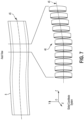
- a tubular structure 8 is divided into a number of discrete sequential cross-sections or rings 46 for a desired resolution.
- the sections or rings 46 can be defined in a plane orthogonal to the longitudinal axis 24.
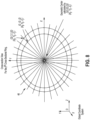
- an outside surface profile of the ring " j " is plotted based on coordinates ( X ij OD , Y ij OD , Z j OD ) in a fixed global coordinate system.
- an inside surface profile of the ring “ j " is plotted based on coordinates ( x ij ID , y ij ID , z j ID ) in a local coordinate system associated with the inner unit 16. If there are M measurements (rings) along a central axis of the tubular structure 8, and N measurements along the circumferential direction, each one of the outside and inside surfaces is represented by a number of measurements that is equal to the value N multiplied by the value M.
- the three-dimensional measurements are presented in a fixed global coordinate system, denoted as ( X ij OD , Y ij OD , Z j OD ) and ( X ij ID , Y ij ID , Z j ID ) for outside and inside surfaces, respectively, in which i is from 1 to N for the circumferential direction, and j is from 1 to M for the axial direction.
- Coordinates of the centerlines of the inside and outside surfaces can then be used to determine the straightness of the tubular structure 8.
- the input data from the laser units 26, 26', 30, 30' are presented in a local coordinate system for each of the insider and outside surfaces.
- a transformation from the local coordinate system to a fixed global coordinate system is implemented.
- the transformation can be performed for input data corresponding to the outside and inside surfaces.
- X Rx + T
- X X Y Z
- translation vector T X 0 Y 0 Z 0
- ⁇ Z is the angle of rotation about the global Z-axis
- ⁇ Y is the angle of rotation about the global Y -axis
- ⁇ X is the angle of rotation about the global X-axis.
- collapse and other performance properties of the tubular structure 8 for each discrete cross-sectional ring along the full length of the tubular structure 8 can be calculated. Also, entire three-dimensional data can be utilized for three-dimensional modeling to accurately predict collapse strength and other performance properties of a specific tubular structure 8.
- the three-dimensional coordinates of the outer and inner surfaces of a tubular structure 8 are obtained and stored in a computer storage system, coordinates defining the centers of any discrete section are calculated.
- the three-dimensional coordinates of the centers of all the discrete sections of the entire length of a tubular good form three-dimensional lines and curves 45.
- a reference base line of straightness of the particular tubular structure or portions thereof In the tubular industry, there is no unique means to define the base reference line for the straightness calculation. The end user may specify the methodology of their preference.
- single trace wall thickness measuring instruments 40 can be incorporated into the inspection system 4 for calibration purposes to ensure that the inside surface profile or shell is placed properly within the outside surface profile or shell.
- two traces, placed outside the rotating drum 22 and approximately 90° apart, are sufficient to lock the inside and outside surface profiles together.
- the single trace instruments 40 could be positioned in the interior of the rotating drum 22.
- suitable single trace instruments 40 include non-overlapping single trace ultrasonic testing (UT), laser-UT, gamma-ray, magnetic and other wall sensing devices.
- the single trace instruments 40 could be substituted or used in conjunction with at least four direct wall measurement points 42, two or more at each end of the tubular structure 8 including the longitudinal separation distance 27, as illustrated in FIGS. 2 , 5 ,and 6 .
- advanced positioning devices such as a separate straightness reference laser beam or a multi-dimensional gyroscope, can be used to determine the off-axis dimensions with respect to the geometrical center coordinates representing discrete longitudinal sections associated with the outside surface or inside surface circumferential measurements.
Landscapes
- Physics & Mathematics (AREA)
- General Physics & Mathematics (AREA)
- Length Measuring Devices By Optical Means (AREA)
Claims (13)
- Verfahren zum Prüfen eines rohrförmigen Guts, das Verfahren umfassend:Auswählen eines Querschnitts des rohrförmigen Guts, der sich quer zu einer Längsachse, die sich durch das rohrförmige Gut erstreckt, befindet;Längspositionieren einer ersten Messeinrichtung an einer ersten Position in Bezug auf den Querschnitt; wobei die erste Messeinrichtung umfasst:eine drehbare Trommel (22), die konfiguriert ist, um sich um die Längsachse des rohrförmigen Guts herum zu drehen, wobei die drehbare Trommel (22) eine zylindrische Gestalt und eine feste Außenhülle (23) aufweist; undmindestens ein erstes Paar Lasereinheiten (26, 26'), das an einer Innenwand der drehbaren Trommel positioniert ist, wobei jede Lasereinheit des mindestens ersten Paars Lasereinheiten an einer gegenüberliegenden Seite einer Innenwand der drehbaren Trommel angeordnet ist, wobei sie in Umfangsrichtung um etwa 180° an der Innenwand der drehbaren Trommel voneinander beabstandet sind;Empfangen, mittels einer Steuerung (12), einer Vielzahl von Messungen von der ersten Messeinrichtung;Bestimmen, mittels der Steuerung (12), einer Vielzahl von Außendurchmessern des rohrförmigen Guts an den diskreten Positionen rund um den Umfang des Querschnitts von der Vielzahl von Messungen von der ersten Messeinrichtung;Längspositionieren einer zweiten Messeinrichtung an einer zweiten Position in Bezug auf den Querschnitt, wobei die zweite Messeinrichtung umfasst:ein Montageelement (28) in der Form eines stationären Dorns, der sich entlang der Längsachse des rohrförmigen Guts erstreckt; undmindestens ein zweites Paar Lasereinheiten, das an einem Drehmotor (17) befestigt ist, der an dem Montageelement (28) angebracht ist und sich von diesem erstreckt, wobei eine erste Lasereinheit des zweiten Paars Lasereinheiten konfiguriert ist, um in eine gegenüberliegende Richtung zu einer zweiten Lasereinheit des zweiten Paars Lasereinheiten entlang einer Achse senkrecht zu der Längsachse des rohrförmigen Guts zu zeigen, und wobei der Drehmotor (17) konfiguriert ist, um die zwei Lasereinheiten des zweiten Paars Lasereinheiten um die Längsachse des rohrförmigen Guts herum zu drehen;Empfangen, mittels der Steuerung (12), einer Vielzahl von Messungen von der zweiten Messeinrichtung;Bestimmen, mittels der Steuerung (12), einer Vielzahl von Innendurchmessern des rohrförmigen Guts an den diskreten Positionen rund um den Umfang des Querschnitts von der Vielzahl von Messungen von der zweiten Messeinrichtung;während sich die erste Messeinrichtung an der ersten Position befindet und sich die zweite Messeinrichtung an der zweiten Position befindet,Bestimmen der Längsposition der ersten Messeinrichtung entlang der Längsachse des rohrförmigen Guts und Bestimmen der Längsposition der zweiten Messeinrichtung entlang der Längsachse des rohrförmigen Guts; während sich die erste Messeinrichtung an der ersten Position befindet und sich die zweite Messeinrichtung an der zweiten Position befindet, Bestimmen der Umfangsposition der ersten und der zweiten Messeinrichtung um den Umfang des Querschnitts herum;Auswählen von Durchmesserabschnitten in diskreten Positionen rund um den Umfang des Querschnitts des rohrförmigen Guts;Wiederholen der oben aufgeführten Schritte an einer Vielzahl von anderen Abschnitten des rohrförmigen Guts, die sich orthogonal zu der Längsachse befinden;Bestimmen eines Außenseitenoberflächenprofils und eines Innenseitenoberflächenprofils des rohrförmigen Guts an jedem der Durchmesserabschnitte in einem festen globalen Koordinatensystem von der Vielzahl von Messungen von der ersten und der zweiten Messeinrichtung, undBestimmen von dreidimensionalen Koordinaten, die die geometrischen Mitten der Außenseiten- und Innenseitenoberfläche für jeden Durchmesserabschnitt definieren, von dem bestimmten Außenseiten- und Innenseitenoberflächenprofil,Kalkulieren einer Referenzbasis einer Geradheit mittels eines Verwendens des Verfahrens der kleinsten Quadrate basierend auf den bestimmten dreidimensionalen Koordinaten der geometrischen Mitten.
- Verfahren nach Anspruch 1, wobei die digitalen Aufzeichnungen umfassen:erste digitale Aufzeichnungen, die konfiguriert sind, um eine Außenoberfläche des rohrförmigen Guts zu definieren; undzweite digitale Aufzeichnungen, die konfiguriert sind, um eine Innenoberfläche des rohrförmigen Guts zu definieren.
- Verfahren nach Anspruch 1, ferner umfassend den Schritt eines Speicherns der digitalen Aufzeichnungen der Außendurchmesser, der Innendurchmesser und der geometrischen Mitte des Querschnitts.
- Verfahren nach Anspruch 2, ferner umfassend den Schritt eines Verknüpfens der Außenoberfläche und der Innenoberfläche des rohrförmigen Guts, um eine Wand des rohrförmigen Guts in einem dreidimensionalen Raum zu kalkulieren.
- Verfahren nach Anspruch 4, ferner umfassend die Schritte:Messen der relativen Position und Entfernung eines geometrischen Mittelpunkts der Außenoberfläche eines Anfangsabschnitts von einem geometrischen Mittelpunkt der Innenoberfläche des Anfangsabschnitts; undMessen der relativen Position und Entfernung eines geometrischen Mittelpunkts der Außenoberfläche eines letzten Abschnitts von dem geometrischen Mittelpunkt der Innenoberfläche des letzten Abschnitts.
- Verfahren nach Anspruch 5, ferner umfassend den Schritt des Verwendens mindestens einiger der digitalen Aufzeichnungen, um die Auswirkung von Stressfaktoren auf die kalkuliere Wand des rohrförmigen Guts zu berechnen.
- Verfahren nach Anspruch 6, ferner umfassend den Schritt des Verwendens mindestens einiger der digitalen Aufzeichnungen, um eine virtuelle dreidimensionale Form des rohrförmigen Guts zu konstruieren.
- System zum Prüfen eines rohrförmigen Guts, das System umfassend: eine Außeneinheit umfassendmindestens eine Außenmessvorrichtung;eine drehbare Trommel (22), die konfiguriert ist, um sich um eine Längsachse des rohrförmigen Guts herum zu drehen, wobei die drehbare Trommel eine zylindrische Gestalt und eine feste Außenhülle aufweist; undein erstes Paar Lasereinheiten (26, 26'), das an einer Innenwand der drehbaren Trommel (22) positioniert ist, wobei jede Lasereinheit des ersten Paars Lasereinheiten an einer gegenüberliegenden Seite einer Innenwand der drehbaren Trommel (22) angeordnet ist, wobei sie in Umfangsrichtung um etwa 180° an der Innenwand der drehbaren Trommel (22) voneinander beabstandet sind;eine Inneneinheit umfassend:ein Montageelement (28) in der Form eines stationären Dorns, der sich entlang der Längsachse des rohrförmigen Guts erstreckt; undein zweites Paar Lasereinheiten, das an einem Drehmotor (17) befestigt ist, der an dem Montageelement (28) angebracht ist und sich von diesem erstreckt, wobei eine Lasereinheit des zweiten Paars Lasereinheiten konfiguriert ist, um in eine gegenüberliegende Richtung zu einer zweiten Lasereinheit des zweiten Paars Lasereinheiten entlang einer Achse senkrecht zu der Längsachse des rohrförmigen Guts zu zeigen, und wobei der Drehmotor (17) konfiguriert ist, um das zweite Paar Lasereinheiten um die Längsachse des rohrförmigen Guts herum zu drehen; undeine Steuerschaltung, die mit dem ersten Paar Lasereinheiten und dem zweiten Paar Lasereinheiten gekoppelt ist, wobei die Steuerschaltung konfiguriert ist, um die Schritte durchzuführen:Auswählen eines Querschnitts des rohrförmigen Guts, der eine Längsachse, die sich durch das rohrförmige Gut erstreckt, schneidet;Längspositionieren der Außeneinheit an einer ersten Position außerhalb des Querschnitts; während sich die Außeneinheit an der ersten Position befindet, Bestimmen der Längsposition der Außeneinheit entlang der Längsachse des rohrförmigen Guts; während sich die Außeneinheit an der ersten Position befindet, Bestimmen der Umfangsposition der Außeneinheit um einen Umfang des Querschnitts herum;Längspositionieren der Inneneinheit an einer zweiten Position innerhalb des Querschnitts; während sich die Inneneinheit an der zweiten Position befindet, Bestimmen der Längsposition der Inneneinheit entlang der Längsachse des rohrförmigen Guts; während sich die Inneneinheit an der zweiten Position befindet, Bestimmen der Umfangsposition der Inneneinheit um den Umfang des Querschnitts herum;Empfangen einer Vielzahl von Messungen von der Außen- und Inneneinheit;Bestimmen einer Vielzahl von Außendurchmessern des rohrförmigen Guts an diskreten Positionen rund um den Umfang des Querschnitts von der Vielzahl von Messungen von der Außeneinheit;Bestimmen einer Vielzahl von Innendurchmessern des rohrförmigen Guts an den diskreten Positionen rund um den Umfang des Querschnitts von der Vielzahl von Messungen von der Inneneinheit;Auswählen von Durchmesserabschnitten in diskreten Positionen rund um den Umfang des Querschnitts des rohrförmigen Guts;Wiederholen der oben aufgeführten Schritte an einer Vielzahl von anderen Abschnitten des rohrförmigen Guts, die sich orthogonal zu der Längsachse befinden;Bestimmen eines Außenseitenoberflächenprofils und eines Innenseitenoberflächenprofils des rohrförmigen Guts an jedem der Durchmesserabschnitte in einem festen globalen Koordinatensystem von der Vielzahl von Messungen von der Innen- und Außeneinheit; undBestimmen von dreidimensionalen Koordinaten, die die geometrischen Mitten der Außenseiten- und Innenseitenoberfläche für jeden Durchmesserabschnitt definieren, von dem bestimmten Außenseiten- und Innenseitenoberflächenprofil,Kalkulieren einer Referenzbasislinie der Geradheit mittels des Verwendens des Verfahrens der kleinsten Quadrate basierend auf den bestimmten dreidimensionalen Koordinaten der geometrischen Mitten.
- System nach Anspruch 8, wobei die Steuerschaltung einen Speicher umfasst und wobei die Steuerschaltung konfiguriert ist, um die digitalen Aufzeichnungen der Außendurchmesser, der Innendurchmesser und der geometrischen Mitte des Querschnitts in dem Speicher zu speichern.
- System nach Anspruch 9, wobei die digitalen Aufzeichnungen umfassen:erste digitale Aufzeichnungen, die konfiguriert sind, um eine Außenoberfläche des rohrförmigen Guts zu definieren; undzweite digitale Aufzeichnungen, die konfiguriert sind, um eine Innenoberfläche des rohrförmigen Guts zu definieren.
- System nach Anspruch 10, ferner umfassend den Schritt des Verknüpfens der Außenoberfläche und der Innenoberfläche des rohrförmigen Guts, um eine Wand des rohrförmigen Guts in dem dreidimensionalen Raum zu kalkulieren.
- System nach Anspruch 11, ferner umfassend eine mittlere Einheit, wobei die Steuerschaltung die mittlere Einheit nutzt, um die Schritte durchzuführen:Messen der relativen Position und Entfernung eines geometrischen Mittelpunkts der Außenoberfläche eines Anfangsabschnitts von einem geometrischen Mittelpunkt der Innenoberfläche des Anfangsabschnitts; undMessen der relativen Position und Entfernung eines geometrischen Mittelpunkts der Außenoberfläche eines letzten Abschnitts von dem geometrischen Mittelpunkt der Innenoberfläche des letzten Abschnitts.
- System nach Anspruch 12, wobei die Steuerschaltung konfiguriert ist, um eine virtuelle dreidimensionale Form des rohrförmigen Guts unter Verwendung mindestens einiger der digitalen Aufzeichnungen, die in dem Speicher gespeichert sind, zu konstruieren.
Applications Claiming Priority (2)
| Application Number | Priority Date | Filing Date | Title |
|---|---|---|---|
| US201662361190P | 2016-07-12 | 2016-07-12 | |
| PCT/US2017/041759 WO2018013715A2 (en) | 2016-07-12 | 2017-07-12 | Methods and systems for measurement and inspection of tubular goods |
Publications (4)
| Publication Number | Publication Date |
|---|---|
| EP3485271A2 EP3485271A2 (de) | 2019-05-22 |
| EP3485271A4 EP3485271A4 (de) | 2020-03-11 |
| EP3485271B1 true EP3485271B1 (de) | 2025-01-22 |
| EP3485271C0 EP3485271C0 (de) | 2025-01-22 |
Family
ID=60940527
Family Applications (1)
| Application Number | Title | Priority Date | Filing Date |
|---|---|---|---|
| EP17828403.0A Active EP3485271B1 (de) | 2016-07-12 | 2017-07-12 | Verfahren und systeme zur messung und inspektion von rohrförmigen waren |
Country Status (14)
| Country | Link |
|---|---|
| US (2) | US10054425B2 (de) |
| EP (1) | EP3485271B1 (de) |
| JP (2) | JP2019527368A (de) |
| KR (1) | KR102096220B1 (de) |
| CN (1) | CN109791128B (de) |
| AU (1) | AU2017297405B2 (de) |
| BR (2) | BR122020005642B1 (de) |
| CA (1) | CA3030425C (de) |
| EA (1) | EA035901B1 (de) |
| ES (1) | ES3017689T3 (de) |
| MX (1) | MX377097B (de) |
| SA (1) | SA519400846B1 (de) |
| UA (1) | UA125071C2 (de) |
| WO (1) | WO2018013715A2 (de) |
Families Citing this family (11)
| Publication number | Priority date | Publication date | Assignee | Title |
|---|---|---|---|---|
| US10121225B1 (en) * | 2018-01-04 | 2018-11-06 | Finger Food Studios, Inc. | Dynamic scaling of visualization data while maintaining desired object characteristics |
| GB2573757A (en) * | 2018-05-14 | 2019-11-20 | Mini Cam Ltd | A pipe inspection apparatus, system and method |
| CN108759687B (zh) * | 2018-08-14 | 2024-04-12 | 国网青海省电力公司检修公司 | Gis设备的位移监测系统和方法 |
| IT201800011031A1 (it) * | 2018-12-12 | 2020-06-12 | Visiorobotics S R L | Sistema di validazione di componenti meccanici |
| WO2021059429A1 (ja) * | 2019-09-26 | 2021-04-01 | 大和鋼管工業株式会社 | 測定装置および測定システム |
| JP7597390B2 (ja) | 2020-03-10 | 2024-12-10 | 大和鋼管工業株式会社 | 鋼管製造システム |
| EP3951233B1 (de) * | 2020-08-04 | 2023-10-18 | Vallourec Oil And Gas France | Interne inspektionsvorrichtung zur bestimmung einer länge eines schlauchförmigen gutes |
| US11486835B2 (en) * | 2020-11-13 | 2022-11-01 | Saudi Arabian Oil Company | Drift and measurement tools and methods |
| US11433701B1 (en) | 2021-08-06 | 2022-09-06 | Cdp Diamond Products, Inc. | Wheel |
| DE102022213730A1 (de) * | 2022-12-15 | 2024-06-20 | Sms Group Gmbh | Verfahren, Messanordnung und System zur Vermessung einer Innenkontur, insbesondere eines Innengewindes an einer Muffe oder einem Muffenende eines Rohres |
| CN119915193A (zh) * | 2025-04-02 | 2025-05-02 | 广州市城市排水有限公司 | 一种激光测径方法和测径仪 |
Family Cites Families (20)
| Publication number | Priority date | Publication date | Assignee | Title |
|---|---|---|---|---|
| US5030911A (en) * | 1980-10-19 | 1991-07-09 | Baker Hughes Incorporated | Method and apparatus for displaying defects in tubular members on a two-dimensional map in a variety of display modes |
| US4725963A (en) * | 1985-05-09 | 1988-02-16 | Scientific Measurement Systems I, Ltd. | Method and apparatus for dimensional analysis and flaw detection of continuously produced tubular objects |
| JPS63165706A (ja) * | 1986-12-27 | 1988-07-09 | Kawasaki Steel Corp | 管端の形状測定装置 |
| US4912683A (en) * | 1988-12-29 | 1990-03-27 | Atlantic Richfield Company | Method for acoustically measuring wall thickness of tubular goods |
| US5007291A (en) * | 1989-10-05 | 1991-04-16 | Scan Systems, Inc. | Ultrasonic inspection apparatus with centering means for tubular members |
| US5313837A (en) * | 1991-09-26 | 1994-05-24 | Ico, Inc. | Ultrasonic thickness gage for pipe |
| JPH07318301A (ja) * | 1994-03-31 | 1995-12-08 | Sankyu Inc | 円筒体の偏肉測定方法及び装置 |
| US6091500A (en) * | 1998-12-16 | 2000-07-18 | Lucent Technologies Inc. | Method and apparatus for measuring overclad tubes |
| US6862099B2 (en) * | 2002-04-05 | 2005-03-01 | Varco I/P | Tubular ovality testing |
| US6931748B2 (en) * | 2002-04-05 | 2005-08-23 | Varco I/P, Inc. | Riser and tubular inspection systems |
| US6745136B2 (en) | 2002-07-02 | 2004-06-01 | Varco I/P, Inc. | Pipe inspection systems and methods |
| CA2559170C (en) | 2003-03-07 | 2013-05-14 | Technical Industries, Inc. | Method for inspection of metal tubular goods |
| NO333307B1 (no) * | 2008-11-24 | 2013-04-29 | Statoil Asa | Anordning og fremgangsmate for optisk maling av tykkelsen av enhver avsetning av materiale pa innerveggen til en konstruksjon |
| JP2011007587A (ja) * | 2009-06-25 | 2011-01-13 | Jfe Steel Corp | 鋼管の寸法測定装置 |
| JP2013092439A (ja) * | 2011-10-26 | 2013-05-16 | Nippon Steel & Sumitomo Metal | 管の内面曲がり測定装置およびそれを用いた測定方法 |
| WO2013095892A1 (en) * | 2011-12-21 | 2013-06-27 | National Oilwell Varco, L.P. | System and method for measuring pipe |
| US20140090674A1 (en) * | 2012-09-28 | 2014-04-03 | Extreme Hydro Solutions, L.L.C. | Knuckle-jointed lance for internal cleaning and inspection of tubulars |
| KR101531294B1 (ko) * | 2013-07-05 | 2015-06-24 | 삼성중공업(주) | 배관 계측 장치 |
| US20160331528A1 (en) * | 2014-01-23 | 2016-11-17 | President And Fellows Of Harvard College | Engineered polymeric valves, tubular structures, and sheets and uses thereof |
| US9335146B1 (en) * | 2014-01-29 | 2016-05-10 | The United States Of America As Represented By The Secretary Of The Navy | Dimensional measurement apparatus for a cylindrical object |
-
2017
- 2017-07-12 US US15/648,225 patent/US10054425B2/en active Active
- 2017-07-12 MX MX2019000417A patent/MX377097B/es active IP Right Grant
- 2017-07-12 KR KR1020197003702A patent/KR102096220B1/ko active Active
- 2017-07-12 CA CA3030425A patent/CA3030425C/en active Active
- 2017-07-12 AU AU2017297405A patent/AU2017297405B2/en active Active
- 2017-07-12 CN CN201780043174.8A patent/CN109791128B/zh active Active
- 2017-07-12 WO PCT/US2017/041759 patent/WO2018013715A2/en not_active Ceased
- 2017-07-12 BR BR122020005642-8A patent/BR122020005642B1/pt active IP Right Grant
- 2017-07-12 EA EA201990266A patent/EA035901B1/ru unknown
- 2017-07-12 EP EP17828403.0A patent/EP3485271B1/de active Active
- 2017-07-12 ES ES17828403T patent/ES3017689T3/es active Active
- 2017-07-12 BR BR112019000611-7A patent/BR112019000611B1/pt active IP Right Grant
- 2017-07-12 UA UAA201900486A patent/UA125071C2/uk unknown
- 2017-07-12 JP JP2019520677A patent/JP2019527368A/ja active Pending
-
2018
- 2018-06-22 US US16/015,891 patent/US10234276B2/en active Active
-
2019
- 2019-01-09 SA SA519400846A patent/SA519400846B1/ar unknown
-
2020
- 2020-07-28 JP JP2020127753A patent/JP7064536B2/ja active Active
Also Published As
| Publication number | Publication date |
|---|---|
| US10234276B2 (en) | 2019-03-19 |
| JP7064536B2 (ja) | 2022-05-10 |
| AU2017297405B2 (en) | 2019-10-24 |
| EA035901B1 (ru) | 2020-08-28 |
| CN109791128B (zh) | 2021-11-16 |
| US20190017809A1 (en) | 2019-01-17 |
| CA3030425A1 (en) | 2018-01-18 |
| US10054425B2 (en) | 2018-08-21 |
| BR112019000611A2 (pt) | 2019-07-02 |
| JP2019527368A (ja) | 2019-09-26 |
| JP2020197535A (ja) | 2020-12-10 |
| BR112019000611B1 (pt) | 2023-10-03 |
| KR102096220B1 (ko) | 2020-05-18 |
| SA519400846B1 (ar) | 2022-07-20 |
| AU2017297405A1 (en) | 2019-02-07 |
| CN109791128A (zh) | 2019-05-21 |
| CA3030425C (en) | 2019-09-17 |
| ES3017689T3 (en) | 2025-05-13 |
| BR122020005642B1 (pt) | 2023-10-03 |
| WO2018013715A2 (en) | 2018-01-18 |
| EA201990266A1 (ru) | 2019-07-31 |
| KR20190041463A (ko) | 2019-04-22 |
| UA125071C2 (uk) | 2022-01-05 |
| EP3485271A2 (de) | 2019-05-22 |
| WO2018013715A3 (en) | 2018-02-22 |
| EP3485271C0 (de) | 2025-01-22 |
| MX2019000417A (es) | 2019-09-19 |
| US20180017376A1 (en) | 2018-01-18 |
| EP3485271A4 (de) | 2020-03-11 |
| MX377097B (es) | 2025-03-07 |
Similar Documents
| Publication | Publication Date | Title |
|---|---|---|
| EP3485271B1 (de) | Verfahren und systeme zur messung und inspektion von rohrförmigen waren | |
| US9400162B2 (en) | Device for measuring an internal or external profile of a tubular component | |
| RU2471145C1 (ru) | Способ контроля параметров точности торцевых поверхностей деталей типа "тело вращения" | |
| EP2880435B1 (de) | Verfahren und system zur bestimmung der position von geometrischen merkmalen bei objekten | |
| Liu et al. | A parallel error separation method for the on-line measurement and reconstruction of cylindrical profiles | |
| JP2015025729A (ja) | 肉厚測定装置を用いた配管の減肉評価方法 | |
| CN101825454A (zh) | 基于双向测量的温度误差补偿方法 | |
| EP3698102A1 (de) | Messvorrichtung und messverfahren für einen gerillten achssymmetrischen körper | |
| CN107120532B (zh) | 基于快速正交搜索算法的管道连接器检测方法 | |
| JP6356579B2 (ja) | 渦電流探傷装置および渦電流探傷方法 | |
| RU2123923C1 (ru) | Способ диагностики токарных станков по параметрам точности и устройство для его осуществления | |
| CN204439047U (zh) | 空间尺寸检测装置 | |
| McGregor et al. | Mobile robot positioning using accelerometers for pipe inspection | |
| Stepien et al. | Research on accurate in situ measurements of cylindricity | |
| RU2739279C1 (ru) | Универсальное устройство дефектоскопии для контроля технического состояния стенок гильз | |
| RU2628041C2 (ru) | Способ компенсации погрешности измерения пройденной дистанции одометрической системой вип с приведением диагностических данных к паспортным длинам трубных секций | |
| WO2024249189A1 (en) | Multi sensing approach for industrial inspection | |
| RU143324U1 (ru) | Устройство для оценки погрешностей формы тел вращения в поперечном сечении | |
| RU2551635C2 (ru) | Универсальное координатное устройство для ручного дефектоскопа | |
| RU2639466C2 (ru) | Способ обработки результатов внутритрубных диагностических обследований магистральных трубопроводов, выполненных комбинированными методами неразрушающего контроля с учетом конструктивных характеристик внутритрубного инспекционного прибора (ВИП), скорости движения и изменения углового положения ВИП | |
| KIM et al. | An Algorithm for 3D Vibration Measurement Using One Laser Scanning Vibrometer | |
| CN104655069A (zh) | 空间尺寸检测装置及检测方法 | |
| Bachnak et al. | Position tracking and flaw visualization in conductive materials | |
| Bachnak et al. | Examining gyroscopes for 3-D position tracking in a non-destructive evaluation system | |
| JP2006194838A (ja) | 電機子コアの検査方法及び検査装置 |
Legal Events
| Date | Code | Title | Description |
|---|---|---|---|
| STAA | Information on the status of an ep patent application or granted ep patent |
Free format text: STATUS: THE INTERNATIONAL PUBLICATION HAS BEEN MADE |
|
| PUAI | Public reference made under article 153(3) epc to a published international application that has entered the european phase |
Free format text: ORIGINAL CODE: 0009012 |
|
| STAA | Information on the status of an ep patent application or granted ep patent |
Free format text: STATUS: REQUEST FOR EXAMINATION WAS MADE |
|
| 17P | Request for examination filed |
Effective date: 20190207 |
|
| AK | Designated contracting states |
Kind code of ref document: A2 Designated state(s): AL AT BE BG CH CY CZ DE DK EE ES FI FR GB GR HR HU IE IS IT LI LT LU LV MC MK MT NL NO PL PT RO RS SE SI SK SM TR |
|
| AX | Request for extension of the european patent |
Extension state: BA ME |
|
| DAV | Request for validation of the european patent (deleted) | ||
| A4 | Supplementary search report drawn up and despatched |
Effective date: 20200212 |
|
| RIC1 | Information provided on ipc code assigned before grant |
Ipc: G01N 27/82 20060101ALI20200206BHEP Ipc: G01B 17/02 20060101ALI20200206BHEP Ipc: G01N 29/26 20060101AFI20200206BHEP Ipc: G01N 27/90 20060101ALI20200206BHEP Ipc: G01B 11/12 20060101ALI20200206BHEP Ipc: G01B 11/10 20060101ALI20200206BHEP |
|
| STAA | Information on the status of an ep patent application or granted ep patent |
Free format text: STATUS: EXAMINATION IS IN PROGRESS |
|
| 17Q | First examination report despatched |
Effective date: 20201216 |
|
| GRAP | Despatch of communication of intention to grant a patent |
Free format text: ORIGINAL CODE: EPIDOSNIGR1 |
|
| STAA | Information on the status of an ep patent application or granted ep patent |
Free format text: STATUS: GRANT OF PATENT IS INTENDED |
|
| INTG | Intention to grant announced |
Effective date: 20240816 |
|
| GRAS | Grant fee paid |
Free format text: ORIGINAL CODE: EPIDOSNIGR3 |
|
| GRAA | (expected) grant |
Free format text: ORIGINAL CODE: 0009210 |
|
| STAA | Information on the status of an ep patent application or granted ep patent |
Free format text: STATUS: THE PATENT HAS BEEN GRANTED |
|
| AK | Designated contracting states |
Kind code of ref document: B1 Designated state(s): AL AT BE BG CH CY CZ DE DK EE ES FI FR GB GR HR HU IE IS IT LI LT LU LV MC MK MT NL NO PL PT RO RS SE SI SK SM TR |
|
| REG | Reference to a national code |
Ref country code: GB Ref legal event code: FG4D |
|
| REG | Reference to a national code |
Ref country code: CH Ref legal event code: EP |
|
| REG | Reference to a national code |
Ref country code: IE Ref legal event code: FG4D |
|
| REG | Reference to a national code |
Ref country code: DE Ref legal event code: R096 Ref document number: 602017087464 Country of ref document: DE |
|
| U01 | Request for unitary effect filed |
Effective date: 20250220 |
|
| U07 | Unitary effect registered |
Designated state(s): AT BE BG DE DK EE FI FR IT LT LU LV MT NL PT RO SE SI Effective date: 20250227 |
|
| REG | Reference to a national code |
Ref country code: ES Ref legal event code: FG2A Ref document number: 3017689 Country of ref document: ES Kind code of ref document: T3 Effective date: 20250513 |
|
| REG | Reference to a national code |
Ref country code: SK Ref legal event code: T3 Ref document number: E 46278 Country of ref document: SK |
|
| PG25 | Lapsed in a contracting state [announced via postgrant information from national office to epo] |
Ref country code: RS Free format text: LAPSE BECAUSE OF FAILURE TO SUBMIT A TRANSLATION OF THE DESCRIPTION OR TO PAY THE FEE WITHIN THE PRESCRIBED TIME-LIMIT Effective date: 20250422 |
|
| PG25 | Lapsed in a contracting state [announced via postgrant information from national office to epo] |
Ref country code: PL Free format text: LAPSE BECAUSE OF FAILURE TO SUBMIT A TRANSLATION OF THE DESCRIPTION OR TO PAY THE FEE WITHIN THE PRESCRIBED TIME-LIMIT Effective date: 20250122 |
|
| PG25 | Lapsed in a contracting state [announced via postgrant information from national office to epo] |
Ref country code: IS Free format text: LAPSE BECAUSE OF FAILURE TO SUBMIT A TRANSLATION OF THE DESCRIPTION OR TO PAY THE FEE WITHIN THE PRESCRIBED TIME-LIMIT Effective date: 20250522 Ref country code: NO Free format text: LAPSE BECAUSE OF FAILURE TO SUBMIT A TRANSLATION OF THE DESCRIPTION OR TO PAY THE FEE WITHIN THE PRESCRIBED TIME-LIMIT Effective date: 20250422 |
|
| PG25 | Lapsed in a contracting state [announced via postgrant information from national office to epo] |
Ref country code: HR Free format text: LAPSE BECAUSE OF FAILURE TO SUBMIT A TRANSLATION OF THE DESCRIPTION OR TO PAY THE FEE WITHIN THE PRESCRIBED TIME-LIMIT Effective date: 20250122 |
|
| PG25 | Lapsed in a contracting state [announced via postgrant information from national office to epo] |
Ref country code: GR Free format text: LAPSE BECAUSE OF FAILURE TO SUBMIT A TRANSLATION OF THE DESCRIPTION OR TO PAY THE FEE WITHIN THE PRESCRIBED TIME-LIMIT Effective date: 20250423 |
|
| PGFP | Annual fee paid to national office [announced via postgrant information from national office to epo] |
Ref country code: SK Payment date: 20250618 Year of fee payment: 9 |
|
| PGFP | Annual fee paid to national office [announced via postgrant information from national office to epo] |
Ref country code: CZ Payment date: 20250623 Year of fee payment: 9 |
|
| U20 | Renewal fee for the european patent with unitary effect paid |
Year of fee payment: 9 Effective date: 20250728 |
|
| PG25 | Lapsed in a contracting state [announced via postgrant information from national office to epo] |
Ref country code: SM Free format text: LAPSE BECAUSE OF FAILURE TO SUBMIT A TRANSLATION OF THE DESCRIPTION OR TO PAY THE FEE WITHIN THE PRESCRIBED TIME-LIMIT Effective date: 20250122 |
|
| PGFP | Annual fee paid to national office [announced via postgrant information from national office to epo] |
Ref country code: ES Payment date: 20250801 Year of fee payment: 9 |
|
| PGFP | Annual fee paid to national office [announced via postgrant information from national office to epo] |
Ref country code: TR Payment date: 20250709 Year of fee payment: 9 |
|
| PGFP | Annual fee paid to national office [announced via postgrant information from national office to epo] |
Ref country code: GB Payment date: 20250728 Year of fee payment: 9 |
|
| PLBE | No opposition filed within time limit |
Free format text: ORIGINAL CODE: 0009261 |
|
| STAA | Information on the status of an ep patent application or granted ep patent |
Free format text: STATUS: NO OPPOSITION FILED WITHIN TIME LIMIT |