EP2880435B1 - Verfahren und system zur bestimmung der position von geometrischen merkmalen bei objekten - Google Patents
Verfahren und system zur bestimmung der position von geometrischen merkmalen bei objekten Download PDFInfo
- Publication number
- EP2880435B1 EP2880435B1 EP13747542.2A EP13747542A EP2880435B1 EP 2880435 B1 EP2880435 B1 EP 2880435B1 EP 13747542 A EP13747542 A EP 13747542A EP 2880435 B1 EP2880435 B1 EP 2880435B1
- Authority
- EP
- European Patent Office
- Prior art keywords
- ultrasound
- geometric feature
- response
- transducer
- predicted
- Prior art date
- Legal status (The legal status is an assumption and is not a legal conclusion. Google has not performed a legal analysis and makes no representation as to the accuracy of the status listed.)
- Active
Links
Images
Classifications
-
- G—PHYSICS
- G01—MEASURING; TESTING
- G01N—INVESTIGATING OR ANALYSING MATERIALS BY DETERMINING THEIR CHEMICAL OR PHYSICAL PROPERTIES
- G01N29/00—Investigating or analysing materials by the use of ultrasonic, sonic or infrasonic waves; Visualisation of the interior of objects by transmitting ultrasonic or sonic waves through the object
- G01N29/04—Analysing solids
-
- G—PHYSICS
- G01—MEASURING; TESTING
- G01B—MEASURING LENGTH, THICKNESS OR SIMILAR LINEAR DIMENSIONS; MEASURING ANGLES; MEASURING AREAS; MEASURING IRREGULARITIES OF SURFACES OR CONTOURS
- G01B17/00—Measuring arrangements characterised by the use of infrasonic, sonic or ultrasonic vibrations
-
- G—PHYSICS
- G01—MEASURING; TESTING
- G01D—MEASURING NOT SPECIALLY ADAPTED FOR A SPECIFIC VARIABLE; ARRANGEMENTS FOR MEASURING TWO OR MORE VARIABLES NOT COVERED IN A SINGLE OTHER SUBCLASS; TARIFF METERING APPARATUS; MEASURING OR TESTING NOT OTHERWISE PROVIDED FOR
- G01D5/00—Mechanical means for transferring the output of a sensing member; Means for converting the output of a sensing member to another variable where the form or nature of the sensing member does not constrain the means for converting; Transducers not specially adapted for a specific variable
- G01D5/12—Mechanical means for transferring the output of a sensing member; Means for converting the output of a sensing member to another variable where the form or nature of the sensing member does not constrain the means for converting; Transducers not specially adapted for a specific variable using electric or magnetic means
-
- G—PHYSICS
- G01—MEASURING; TESTING
- G01N—INVESTIGATING OR ANALYSING MATERIALS BY DETERMINING THEIR CHEMICAL OR PHYSICAL PROPERTIES
- G01N29/00—Investigating or analysing materials by the use of ultrasonic, sonic or infrasonic waves; Visualisation of the interior of objects by transmitting ultrasonic or sonic waves through the object
- G01N29/04—Analysing solids
- G01N29/043—Analysing solids in the interior, e.g. by shear waves
-
- G—PHYSICS
- G01—MEASURING; TESTING
- G01N—INVESTIGATING OR ANALYSING MATERIALS BY DETERMINING THEIR CHEMICAL OR PHYSICAL PROPERTIES
- G01N29/00—Investigating or analysing materials by the use of ultrasonic, sonic or infrasonic waves; Visualisation of the interior of objects by transmitting ultrasonic or sonic waves through the object
- G01N29/04—Analysing solids
- G01N29/06—Visualisation of the interior, e.g. acoustic microscopy
- G01N29/0654—Imaging
- G01N29/069—Defect imaging, localisation and sizing using, e.g. time of flight diffraction [TOFD], synthetic aperture focusing technique [SAFT], Amplituden-Laufzeit-Ortskurven [ALOK] technique
-
- G—PHYSICS
- G01—MEASURING; TESTING
- G01N—INVESTIGATING OR ANALYSING MATERIALS BY DETERMINING THEIR CHEMICAL OR PHYSICAL PROPERTIES
- G01N29/00—Investigating or analysing materials by the use of ultrasonic, sonic or infrasonic waves; Visualisation of the interior of objects by transmitting ultrasonic or sonic waves through the object
- G01N29/04—Analysing solids
- G01N29/07—Analysing solids by measuring propagation velocity or propagation time of acoustic waves
-
- G—PHYSICS
- G01—MEASURING; TESTING
- G01N—INVESTIGATING OR ANALYSING MATERIALS BY DETERMINING THEIR CHEMICAL OR PHYSICAL PROPERTIES
- G01N29/00—Investigating or analysing materials by the use of ultrasonic, sonic or infrasonic waves; Visualisation of the interior of objects by transmitting ultrasonic or sonic waves through the object
- G01N29/44—Processing the detected response signal, e.g. electronic circuits specially adapted therefor
- G01N29/4409—Processing the detected response signal, e.g. electronic circuits specially adapted therefor by comparison
- G01N29/4418—Processing the detected response signal, e.g. electronic circuits specially adapted therefor by comparison with a model, e.g. best-fit, regression analysis
Definitions
- Embodiments of the present invention relate generally to the field of ultrasound inspection systems, and specifically, to a method and system for determination of geometric features in objects.
- Ultrasound inspections are used to determine the presence of geometric features such as welds, porosity, corrosion, slag, cracks, and welding defects in the objects.
- the object In ultrasound inspection the object is exposed to ultrasound beams from transducers placed across the length of the object. Responses to the incident ultrasound beams from different parts in the object are collected by the transducers. The amplitudes of the responses are then analyzed to locate geometric features in the object.
- an object is passed through an array of transducers arranged in a particular order to transmit ultrasonic beams into the object with various angles of incidence. Every region of interest within the object to be inspected is passed through this configuration of transducers to generate responses to the ultrasound beams transmitted from each transducer. Hence, interrogation of each object yields a large amount of data during testing. The large amount of data thus received is utilized to generate response charts that plot the amplitudes of the responses against positions of the geometric features in the object with respect to a reference point on the object. The reference point is typically fixed by an operator of the inspection system. Thus, to accurately locate a geometric object, the operator has to manually sift through multiple response charts that display output obtained from the geometric features as a result of the ultrasound beams from different transducers in the configuration.
- ultrasound transducers are arranged to inspect the pipe. Each transducer scans the pipe and generates geometric feature responses at fixed points along the circumference of the pipe. Response data generated for one transducer for one pipe, thus, requires several kilobytes of memory storage space. Response data from the inspection system for the entire pipe, therefore, amounts to requiring megabytes of memory space.
- ultrasound inspection systems store only a part of the data obtained from the transducers by selecting specific positions in the object to generate response charts. For example, in certain systems maximum amplitudes observed at locations between fixed distances in the object are used to generate the response chart.
- EP 2 439 527 A1 describes measuring pipeline wall thickness as a function of position using ultrasound propagation; a series of predictive models are used, which define predictions of the ultrasound response signals as a function of different sets of parameters.
- US 2003/101007 A1 is directed to a system and method for detecting defects in a manufactured object; the system uses an ultrasound measurement system, a signal analyzer and an expected result, wherein the signal analyzer compares the signal from the measurement signal to the expected result.
- US 2010/299095 A1 describes a computer implemented method, apparatus, and computer usable program code for testing a material; a signal is sent into the material, an actual response is received, and a simulated response is generated using a functional model. The simulated response is compared to the actual response to detect a change in the material.
- Embodiments of the invention described herein relate to a method and a system for the determination of geometric features in an object.
- Ultrasound beams which are produced using a plurality of ultrasound transducers, are transmitted so as to be incident on the object being inspected.
- the ultrasound transducers are arranged to cover the entire geometry of the area of the object to be inspected.
- One or more geometric features in the object cause a change in the ultrasound beam in the object and this change in the ultrasound beam is termed a geometric feature response. Examples of changes in the ultrasound beam include, but are not limited to, reflection, scattering, refraction, and deviation in the path of the beam.
- These responses are received by the ultrasound transducers and are processed to obtain amplitude and time of flight information.
- the amplitude and time of flight information of the geometric feature responses are processed to determine the location of the one or more geometric features in the object.
- a volumetric representation of the object is generated.
- the volumetric representation of the object is generated using a plurality of object parameters such as the length of the object, diameter of the object, and thickness of the object.
- a temporal map of a predicted time of flight geometric feature responses is generated. The temporal map is generated based on a predicted ultrasound beam traversal path. The predicted ultrasound beam traversal path is generated based on a plurality of transducer parameters and the volumetric representation of the object.
- the transducer parameters utilized to generate the beam traversal path include, but are not limited to, angle of incidence of the transducer, size of the transducer, geometry of the transducer, and the position of the transducer with respect to the object.
- the received geometric responses are then compared with the temporal map to determine the location of the geometric feature on the volumetric representation.
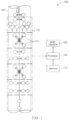
- FIG. 1 illustrates an exemplary embodiment of an ultrasound inspection system 100.
- the ultrasound inspection system 100 includes an object 102 being tested, a plurality of ultrasound transducers 104, a processor 106, a user interface 108, and a memory 110.
- the ultrasound inspection system 100 non-destructively tests the object 102 to find the presence and location of geometric features in the object.
- the object being tested 102 can be a hollow structure or a solid structure.
- examples of object 102 include, but are not limited to, pipes, sheets, rods, nozzles, and billets.
- the geometric features being inspected through the ultrasound inspection system 100 include, but are not limited to, anomalies in the object 102, cracks, welds, defects in welds, porosity, corrosion, and slag, for example.
- Different configurations based on the arrangement of the plurality of ultrasound transducers 104 with respect to the object 102, are possible to ensure that the relevant object geometry is covered.
- Different types of transducer configurations include, but are not limited to longitudinal, transverse, heat affected zone (HAZ) and tandem configuration of transducers.
- the ultrasound transducer 104 configuration shown in FIG. 1 is decided based on the type of geometric feature to be located.
- the angles at which the transducers 104 are arranged with respect to the object 102 provide for different incident angles to the ultrasound beams transmitted by the transducers 104.
- the plurality of ultrasound transducers 104 can be unidirectional transducers or bi-directional transducers.
- the transducers 104 may represent Electromagnetic Acoustic Transducers (EMATs) used to generate ultrasound beams that are incident on the object 104.
- EMATs Electromagnetic Acoustic Transducers
- the processor 106 may comprise a central processing unit (CPU) such as a microprocessor, or may comprise any suitable number of application specific integrated circuits working in cooperation to accomplish the functions of a CPU.
- the processor 106 may include a memory 110.
- the memory 110 can be an electronic, a magnetic, an optical, an electromagnetic, or an infrared system, apparatus, or device. Common forms of memory 110 include hard disks, magnetic tape, Random Access Memory (RAM), a Programmable Read Only Memory (PROM), and EEPROM, or an optical storage device such as a re-writeable CDROM or DVD, for example.
- the processor 106 is capable of executing program instructions, related to the system for determining geometric features in the object 102, and functioning in response to those instructions or other activities that may occur in the course of determining geometric features.
- Such program instructions will comprise a listing of executable instructions for implementing logical functions. The listing can be embodied in any computer-readable medium for use by or in connection with a computer-based system that can retrieve, process, and execute the instructions. Alternatively, some or all of the processing may be performed remotely by additional processors 106.
- the ultrasound transducers 104 may be placed on a stationary electronic arm or a movable electronic arm, for example.
- the processor 106 may be configured to move such an electronic arm (not shown) holding the transducers 104 along the length of the object 102 to cover the geometry to be inspected.
- the electronic arm may be held stationary while the object 102 is moved across the array of ultrasound transducers 104.
- both the electronic arm and the object 102 may be moved in coordination such that ultrasound beams from the transducers 104 can be transmitted so as to be incident on the area of the object 102 to be inspected.
- the object 102 may be placed on a movable rail to move and/or rotate the object 102.
- the ultrasound transducers 104 may be placed in a handheld probe assembly that may be moved along the length of the object 102 for inspection by an operator.
- each of the ultrasound transducers 104 generate and transmit ultrasound beams to be incident on the object 102.
- the ultrasound beams travel from the ultrasound transducers 104 into the object 102 and geometric feature responses, caused due to the presence of geometric features in the object 102, are received by the transducers 104.
- the ultrasound transducers 104 when bidirectional, are configured to receive the responses from the geometric features in the object 102.
- one transducer 104 transmits the ultrasound beam
- another transducer 104 is arranged so as to collect the responses from the geometric features in the object 102.
- two transducers 104 are placed on one side of the area of interest of the object 102 to transmit ultrasound beams, and one transducer 104 is placed to receive the responses from the geometric features.
- the processor 106 receives the geometric feature responses from the transducers 104 to generate a response chart that captures geometric feature response amplitudes from different parts of the object 102.
- the processor 106 is configured to display the response chart on a display screen.
- the processor 106 is configured to display the response on the user interface 108.
- the response chart generated by the processor 106 is then analyzed by the operator to determine the presence and location of geometric features in the object 102. During analysis, an amplitude threshold is defined for the geometric feature response. The operator identifies those positions corresponding with amplitudes greater than the defined threshold as being positions corresponding to the geometric features.
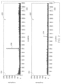
- An exemplary response chart for the ultrasound inspection system 100 is provided in FIG. 2 .
- a reference run of the inspection may be carried out by the ultrasound imaging system 100.
- ultrasound beams generated from the ultrasound transducers 104 are transmitted to be incident on a reference object with known locations of geometric features. Amplitudes of responses received by the transducers 104 from the reference object are then used to determine if the responses from the known locations of geometric features are above the defined threshold.
- Calibration operations such as changing the position of one or more of the ultrasound transducers 104, may be carried out to ensure that the position determined from the amplitude matches the known location.
- FIG. 2 is an exemplary geometric feature response charts 202 generated by the processor 106 of the ultrasound inspection system 100 from the object 102 and displayed on the user interface 108.
- the response chart 202 in FIG. 2 is a 1- dimensional response chart representing the responses received from the object 102 to the incident ultrasound beam.
- the geometric feature responses that are received by the transducers 104 are stored in the memory 110.
- the processor 106 reads this data stored in the memory 110 to generate the response charts 202.
- the transducers 104 are configured to transmit the geometric feature responses to the processor 106 through a communication channel between the transducers 104 and the processor 106.
- the communication channel may be a wired/wireless network.
- the geometric feature response is transmitted to the processor 106 through a communication channel between the inspection system 100 and the processor 106.
- the processor 106 may be a part of a remote server system that is in communication with the ultrasound inspection system 100.
- the ultrasound transducers 104 may then be coupled to at least one transmitter that is configured to transmit geometric feature responses to the processor 106.
- amplitudes 204 of responses to the incident ultrasound beams from geometric features in the object 102 are plotted against locations 206 of the response in the object 102.
- the amplitudes may represent units of frequency, while the locations 206 of the responses are measured with respect to a reference point on the object 102 and may represent units of length, for example.
- an amplitude threshold is defined by the operator. Positions for which the amplitude values lie above the threshold correspond to locations of the geometric features. For example, if the amplitude of the response corresponding to the point 208 crosses the defined threshold, it may be concluded that a geometric feature is present at a point on the location axis 206 that corresponds to the point 208.
- response charts are generated by the processor 106 for each ultrasound transducer from the transducers 104. The response charts may be observed by the operator either on a paper or via a display.
- the geometry of the object 102 is divided in smaller segments, termed the 'pitch' of the object 102.
- the length of the object 102 may be split in smaller segments 112, where each segment is termed the pitch in the object 102.
- the object 102 may be divided in segments 112 of different sizes.
- the object 102 may also have segments 112 of the same size.
- a maximum value from the amplitudes of responses for every pitch of the object 102 is plotted. Further, in certain embodiments, for each pitch of the object 102, time of flight information is collected for the location corresponding to the maximum amplitude geometric feature response.
- the time of flight information for the responses received by the transducers 104 from different points in the object 102 is used to determine the presence of geometric features in the object 102.
- each of the received geometric feature responses is compared with points in a temporal map of a predicted time of flight geometric feature response.
- the temporal map of the predicted time of flight geometric feature response is generated by the processor 106 based on a predicted beam traversal path.
- the processor 106 generates the predicted beam traversal path based on a plurality of transducer parameters and a volumetric representation of the object 102.
- the volumetric representation of the object 102 is generated by the processor 106 based on a plurality of object parameters.
- the object parameters include, but are not limited to, object thickness, object diameter, object geometry and object length.
- Object geometry includes, but is not limited to, details pertaining to shape of the object 102, angles of curvatures, cone angles, and bends observed in the object 102.
- the object 102 is reconstructed by the processor 106 to generate a 3-dimensional image of the object 102.
- the 3-dimensional image in certain embodiments, is generated by the processor 106 by utilizing 3-dimensional modeling software such as AutoCAD TM and CATIA TM .
- a geometrically proportional physical model of the object 102 is utilized as the volumetric representation of the object 102.
- FIG. 3 illustrates exemplary predicted beam traversal paths 304 of the ultrasound beams transmitted by the transducers 104 in the object 102.
- the predicted beam traversal paths 304 are a representation of a path that the ultrasound beams transmitted by the ultrasound transducers 104 take in the object 102.
- the predicted beam traversal paths 304 are determined based on the volumetric representation of the object 102, and a plurality of transducer parameters specific to the transducers 104.
- the predicted beam traversal paths 304 are generated based on the angle of incidence of the ultrasound transducers 104 from which the ultrasound beams are transmitted.
- the angle of incidence of the transducers 104 is selected based on the area of interest 302 of the object 102 that needs to be inspected.
- the angle of incidence for the transducers 104 is selected such that ultrasound beam is incident on the entire desired area of interest 302. Further, the location of the transmitting ultrasound transducers 104 along the object 102, and operating frequency of the transmitting transducers 104 also influence the beam traversal paths 304 in the object 102. In other embodiments, a skew angle (i.e. whether the transducers 104 are "in plane” or "out of plane” with respect to the object 102) associated with the transducers 104 may also be utilized to generate the predicted beam traversal paths 304. In certain embodiments, an operator of the system 100 provides the plurality of transducer parameters to the processor 106 through the user interface 108.
- item 306 represents the points of origin of the beams 304 from the transducers 104.
- the beams originate from the points 306 in the ultrasound transducers 104 and undergo redirections within the object 102.
- the beams continue to travel in the object 102 and, in certain embodiments, may undergo multiple redirections in path.
- Item 308 is an exemplary point of redirection for the beams 304 in the object 102.
- the determination of the beam traversal paths 304 involves determination of the beam traversal path length along with the points of redirection.
- the path length and the points of redirection are determined based on the angle of incidence of the transmitting ultrasound transducers 104 and physical principles that govern beam propagation in the object 102. Principles such as Ultrasound Ray Theory, Snell's Law of refraction, laws of acoustic reflection, and Fermat's principle that determine how beams travel through solid and gaseous bodies are utilized to determine the predicted beam traversal paths 304.
- Unfocused ultrasound beams are transmitted with a cone angle that governs a lateral spread of the beam, termed beam spread, along the beam traversal path.
- the ultrasound beam spread for the beam emanating from the transducers 104 is determined based on the size of the transducers 104, geometry of the transducers 104, and the angle of incidence of the transducers 104.
- the determined beam spread for the beam emanating from the transducers 104 is applied across the beam traversal path length to generate the predicted beam traversal paths 304.
- the speed of sound in the object 102 is constant.
- the speed of sound can also be calculated at different locations in the object 102.
- the speed of sound at different locations influences the predicted beam traversal paths 304.
- the speed of sound at different locations is utilized to correct the predicted beam traversal paths 304.
- the speed of sound in the object 102 may be calculated by utilizing transducers 104 located at two points along the object 102. One of the transducers 104 transmits the ultrasound beam, and another transducer 104 receives the transmitted ultrasound beam. Based on the known distance between the transducers 104, and the time taken by the by ultrasound beam to travel from one transducer 104 to the other transducer 104, the speed of sound is calculated.
- the temporal map of the predicted time of flight geometric feature response for each of the incident ultrasound beams is determined.
- the respective predicted beam traversal path 304 is divided into smaller rays. Over each ray path, presence of geometric features is assumed.
- the predicted beam traversal path 304 is also utilized to determine a path of the response back to the transducers 104.
- the speed of the ultrasound beam in the object 102 and distance covered by the ultrasound beam from the origin 306 of the beam on the beam traversal path 304 to the assumed geometric feature and the beam's return to the transducers 104 are utilized to calculate the time of flight for the ultrasound beam from each geometric feature in the ray path.
- the temporal map of the predicted time of flight geometric feature response is a list of time of flight information for each of the ultrasound beams calculated based on the assumption of the presence of geometric features along every ray in each predicted beam traversal path 304.
- the reference run of inspection is utilized to calculate the speed of the ultrasound beam in the object 102.
- ultrasound beams from one transducer 104 are transmitted so as to be incident on the geometric feature.
- the time of flight of the geometric feature response thus collected is used to calculate the speed of the ultrasound beam.
- Geometric feature responses collected for ultrasound beams transmitted by multiple transducers 104 may also be used to calculate the speed of ultrasound beams in the object 102.
- the temporal map of the predicted time of flight geometric feature response is then compared with the received geometric feature response.
- the received geometric feature response includes time of flight information for the locations within the object 102 where the amplitude of the geometric feature response is greater than the defined threshold.
- the location corresponding to a point from the temporal map of the predicted time of flight geometric feature response that is equivalent to the time of flight of the received geometric feature response is determined as the location of the geometric feature.
- the temporal map of the predicted time of flight geometric feature response is generated based on the predicted beam traversal path 304 for ultrasound beams originating from more than one transducer 104 that are arranged at an angle with respect to the object 102 to be able to transmit ultrasound beams that can be incident on the area of interest of the object 102.
- the two transducers 104 are arranged on the object 102 to transmit ultrasound beams into the same area of interest 302 of the object 102.
- two predicted beam traversal paths 304 from two transducers 104 are determined.
- the location of a geometric feature in the area of interest 304 is determined individually based on each of the predicted beam traversal paths 304.
- the locations determined through two different predicted beam traversal paths 302 are compared to determine the final location of the geometric feature.
- the amplitude information of the geometric feature responses received by the transducers 104 may be utilized to determine the size of the geometric feature. For example, for a particular geometric feature response it may be determined from the predicted beam traversal path 304 whether the ultrasound beam was incident on the geometric feature or whether the geometric feature was present at one of the edges of the ultrasound beam. Hence, the amplitude of the geometric feature response for such an ultrasound beam may not give an accurate estimate of the size of the geometric feature.
- the predicted beam traversal path 304 for other transducers 104 may be utilized to determine the ultrasound beam that is incident on the particular geometric feature and the size of the geometric feature may be determined based on the amplitude information included in the geometric feature response for the other transducer 104.
- FIG 4 illustrates an exemplary representation of the location of geometric features on a volumetric representation of an object according to one embodiment of the present invention.
- Item 404 depicts locations of one or more geometric features in the volumetric representation 402 of the object 102.
- the volumetric representation 402 of the object 102 is generated based on object parameters like object size, object diameter, and object thickness.
- the object parameters are provided to the processor 106, in certain embodiments, by the operator through the user interface 108 to generate the volumetric representation 402.
- the volumetric representation 402 is further used, along with physical principles that govern beam propagation, to determine the predicted beam traversal path 304.
- the predicted beam traversal path 304 is divided in smaller segments and defects are assumed to be located along the beam traversal path 304 in each of the segments.
- the temporal map of predicted time of flight geometric feature response to the incident ultrasound beam is determined based on the assumed defect locations. Further, the received geometric feature response is compared to the predicted geometric feature response.
- the received geometric feature response is provided to the processor 106 for comparison with the predicted time of flight geometric feature response through the user interface 108. In other embodiments, the received geometric feature response may be read by the processor 106 from the memory 110 for comparison.
- a point in the volumetric representation 402 of the object 102 may be determined to be the location of the geometric feature when the time of flight of the received geometric feature response is equivalent to the predicted time of flight geometric feature response corresponding to the point.
- the item 404 depicts the points where the time of flight of the received geometric feature response is equivalent to the predicted time of flight geometric feature response.
- a longitudinal section in the predicted beam traversal path 304 for which the predicted time of flight geometric feature response may be equivalent to the received geometric feature response may be determined as the location of the geometric feature.
- the location of the geometric feature may be a band of points in the volumetric representation 402 of the object 102.
- the locations of the geometric features are displayed with respect to coordinates of the points 404 on X, Y, and Z axes 406.
- Axes 406 respectively run along the length, width, and height of the volumetric representation 402 of the object 102.
- the location for points 404 is expressed in terms of corresponding points on the X, Y, and Z axes.
- the point 404 is displayed on the volumetric representation 402 on the user interface 108.
- the processor 106 determines the point 404 for which the corresponding predicted time of flight geometric feature response is equivalent to the received geometric feature response entered by the operator and displays the point 404 on the volumetric representation 402 on the user interface 108.
- the processor 106 compares the entered time of flight with each point from the temporal map of the predicted time of flight geometric response. Each point in the predicted time of flight geometric response is spatially located on the volumetric representation 402 of the object 102.
- the point 404 for which the entered time of flight equals the predicted time of flight geometric feature response is determined as the location of the geometric feature.
- the location of the geometric feature in certain embodiments, may be displayed on the user interface 108 as a function of the axes 406.
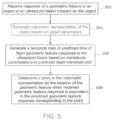
- FIG. 5 is a flow diagram illustrating a method for determining the location of geometric features in the object 102.
- ultrasound beams generated from one of the plurality of transducers 104 are transmitted to be incident on the object 102.
- a response of the geometric feature to the incident ultrasound beam is received by one of the transducers 104.
- a volumetric representation 402 of the object 102 is generated based on the plurality of object parameters.
- the object parameters may include object size, thickness, and diameter, for example.
- a temporal map of a predicted time of flight geometric feature response is generated. The predicted time of flight geometric feature response is generated based on the predicted ultrasound beam traversal path 302 in the object 102.
- the predicted ultrasound beam traversal path 302 is generated based on the volumetric representation 402 and a plurality of transducer parameters.
- Transducer parameters that influence the predicted beam traversal path 302 from the transducer 104 transmitting the ultrasound beam include, but are not limited to, angle of incidence of the transducer 104, position of the transducer 104 with respect to the object 102, geometry of the transducer 104, and frequency of the transducer 104.
- a point 404 on the volumetric representation 402 is determined as the location of the geometric feature when the time of flight of the received geometric feature response is equivalent to the predicted time of flight geometric feature response corresponding to the point 404.
- the predicted time of flight geometric feature response is calculated by assuming presence of no single defect along the beam traversal path 304.
- the received geometric feature response is then compared with such a predicted time of flight geometric feature response by the processor 106.
- the presence of a geometric feature is detected by the processor 106.
- the points 404 may be color-coded to indicate at least one of a magnitude of the geometric feature, and accuracy of the determination of the location of the geometric feature response.
- the magnitude of the geometric feature for example the size of the anomaly being detected, may be determined based on the amplitude of the geometric feature response for the ultrasound beam.
- the location of the point 404 on the object 102 is stored in the memory 110.
- the information stored in the memory 110 is utilized to calibrate errors that may occur when determining geometric features in a new object.
- the processor 106 is configured to compare the location of the point 404 stored in the memory 110 with an actual location of the geometric feature in the object 102. The comparison is utilized to calibrate an error that occurs in the determination of the geometric features in the object 102.
- the reference run of inspection carried out before the object 102 is being inspected may be utilized to calibrate the speed of the ultrasound beam in the object 102.
- the time of flight information is received for the known geometric feature.
- the predicted beam traversal path 304 is determined for the reference run and the location of the known geometric feature is determined utilizing the aforementioned technique. If the location of the geometric feature is observed to be different from the known location, the speed of the ultrasound beam may be adjusted such that the determined location matches the known location of the geometric feature.
- the received geometric feature response and the predicted time of flight geometric response are compared to determine an orientation of the geometric feature in the object 102 being tested.
- the processor 106 may determine an orientation angle of the geometric feature with respect to the object 102, through the predicted beam traversal path 304. Further, in certain embodiments, it may also be determined whether the geometric feature is oriented at an angle with respect to a normal axis of the object 102 by comparing geometric feature responses received from the geometric feature to multiple ultrasound beams transmitted by the transducer 104 from different positions along the object 102.
- the predicted time of flight geometric feature response is compared with the received geometric feature response to determine a configuration of transducers 104 required to cause the transmitted ultrasound beams to be incident on the geometric feature at a required angle.
- a point of incidence of the ultrasound beam for the ray from the predicted beam traversal path 304 that has a geometric feature response equivalent to the received geometric feature response is determined. The point of incidence is then used to change the configuration of transducers 104 in such a way that the incident ultrasound beam meets the object 102 at the required angle.
- Various embodiments described above thus provide for a method and a system for determination of geometric features in the object.
- the determination of location on the volumetric representation provides for an intuitive representation of the geometric feature in the object.
- the volumetric display also provides an accurate location of the defect that allows operators to take faster corrective actions.
- the system and the method reduce the complexity involved in interpreting the currently available response chart from ultrasound inspection systems.
- limited information available from transducers is utilized to determine the location of geometric features, thus reducing the amount of processing time to determine the locations.
- multiple transducers or multiple incident angles of ultrasound beams incident on the geometric features are also utilized to refine determination of location of the geometric features.
Landscapes
- Physics & Mathematics (AREA)
- General Physics & Mathematics (AREA)
- Biochemistry (AREA)
- Life Sciences & Earth Sciences (AREA)
- Chemical & Material Sciences (AREA)
- Analytical Chemistry (AREA)
- Health & Medical Sciences (AREA)
- General Health & Medical Sciences (AREA)
- Immunology (AREA)
- Pathology (AREA)
- Acoustics & Sound (AREA)
- Engineering & Computer Science (AREA)
- Signal Processing (AREA)
- Investigating Or Analyzing Materials By The Use Of Ultrasonic Waves (AREA)
Claims (14)
- Verfahren (500) zum Bestimmen einer Stelle von mindestens einem geometrischen Merkmal, umfassend eine Anomalie, die in einem Objekt (102) beobachtet wird, das Verfahren umfassend:Empfangen (502) von mindestens einer Reaktion des geometrischen Merkmals auf Ultraschallstrahlen, die auf das Objekt (102) auftreffen, wobei die Ultraschallstrahlen von einer Vielzahl von Ultraschallwandlern (104) produziert werden;Erzeugen (504) einer volumetrischen Darstellung (402) des Objekts (102) basierend auf einer Vielzahl von Objektparametern;Erzeugen (506) einer zeitlichen Karte einer vorhergesagten Reaktion des geometrischen Merkmals über eine Laufzeit auf die Ultraschallstrahlen, basierend auf einem vorhergesagten Ultraschallstrahldurchlaufpfad (304) in dem Objekt (102), und ausgehend von mehr als einem Ultraschallwandler (104), die in einem Winkel in Bezug auf das Objekt (102) angeordnet sind, um Ultraschallstrahlen aussenden zu können, die auf einen Bereich von Interesse des Objekts (102) auftreffen, wobei der vorhergesagte Ultraschallstrahldurchlaufpfad (304) basierend auf der volumetrischen Darstellung (402) des Objekts (102) und einer Vielzahl von Wandlerparametern erzeugt wird, und wobei die zeitliche Karte der vorhergesagten Reaktion des geometrischen Merkmals über die Laufzeit eine Liste von Laufzeitinformationen für jeden der Ultraschallstrahlen ist, die basierend auf einer Annahme eines Vorhandenseins von geometrischen Merkmalen entlang jedes Lichtstrahls in dem vorhergesagten Ultraschallstrahldurchlaufpfad (304) berechnet werden; undBestimmen (508) einer Position (404) auf der volumetrischen Darstellung (402) des Objekts (102) als die Stelle des geometrischen Merkmals, wenn die empfangene Reaktion des geometrischen Merkmals über die Laufzeit gleich der vorhergesagten Reaktion des geometrischen Merkmals über die Laufzeit ist, die der Position entspricht.
- Verfahren nach Anspruch 1, wobei der vorhergesagte Ultraschallstrahldurchlaufpfad (304) eine Darstellung eines Pfads ist, den die Ultraschallstrahlen von dem Ultraschallwandler (104) im Inneren des Objekts (102) nehmen.
- Verfahren nach Anspruch 1 oder 2, ferner umfassend ein Kalibrieren der Vielzahl von Ultraschallwandlern (104) in Bezug auf das Objekt (102) vor einem Erfassen der Reaktionen des geometrischen Merkmals.
- Verfahren nach einem der Ansprüche 1 bis 3, wobei das Empfangen der mindestens einen Reaktion des geometrischen Merkmals ferner das Empfangen eines 1-dimensionalen Reaktionsdiagramms umfasst.
- Verfahren nach Anspruch 4, wobei das 1-dimensionale Reaktionsdiagramm Amplitudeninformationen für die Reaktion umfasst, die von dem geometrischen Merkmal für die Ultraschallstrahlen empfangen wird.
- Verfahren nach einem der vorstehenden Ansprüche, wobei die Vielzahl von Objektparametern mindestens einen von einem Durchmesser des Objekts (102), einer Länge des Objekts (102), einer Geometrie des Objekts (102) und einer Dicke des Objekts (102) umfasst.
- Verfahren nach einem der vorstehenden Ansprüche, wobei die Vielzahl der Wandlerparameter die Stelle des Ultraschallwandlers (104) entlang des Objekts (102), eine Größe des Wandlers (104), einen Einfallswinkel des Wandlers (104) und eine Frequenz des Wandlers (104) umfasst.
- System zum Bestimmen der Stelle von mindestens einem geometrischen Merkmal, umfassend eine Anomalie, die in einem Objekt (102) beobachtet wird, das System umfassend:mehr als ein Ultraschallwandler (104), der konfiguriert ist, um Ultraschallstrahlen in das Objekt (102) auszusenden und mindestens eine Antwort des geometrischen Merkmals auf die Ultraschallstrahlen zu empfangen; undeinen Prozessor (106), der konfiguriert ist zum:Erzeugen einer volumetrischen Darstellung (402) des Objekts (102) basierend auf einer Vielzahl von Objektparametern;Erzeugen einer zeitlichen Karte einer vorhergesagten Reaktion der geometrischen Merkmale über die Laufzeit der Ultraschallstrahlen basierend auf einem vorhergesagten Ultraschallstrahldurchlaufpfad (304) in dem Objekt (102) und ausgehend von den mehr als einem Ultraschallwandler (104), die in einem Winkel in Bezug auf das Objekt (102) angeordnet sind, um Ultraschallstrahlen aussenden zu können, die auf einen Bereich von Interesse des Objekts (102) auftreffen, wobei der vorhergesagte Ultraschallstrahldurchlaufpfad (304) basierend auf der volumetrischen Darstellung (402) des Objekts (102) und einer Vielzahl von Wandlerparametern erzeugt wird, und wobei die zeitliche Karte der vorhergesagten Reaktion des geometrischen Merkmals über die Laufzeit eine Liste von Laufzeitinformationen für jeden der Ultraschallstrahlen ist, die basierend auf einer Annahme einer Anwesenheit geometrischer Merkmale entlang jedes Lichtstrahls in dem vorhergesagten Ultraschallstrahldurchlaufpfad (304) berechnet wird; undBestimmen einer Position (404) auf der volumetrischen Darstellung (304) des Objekts (102) als die Stelle des geometrischen Merkmals, wenn die empfangene Reaktion des geometrischen Merkmals über die Laufzeit gleich der vorhergesagten Reaktion des geometrischen Merkmals über die Laufzeit ist, die der Position (404) entspricht.
- System nach Anspruch 8, wobei der vorhergesagte Ultraschallstrahldurchlaufpfad (304) eine Darstellung eines Pfads ist, den die Ultraschallstrahlen von dem Ultraschallwandler (104) im Inneren des Objekts (102) nehmen.
- System nach Anspruch 8 oder 9, das ferner eine Benutzerschnittstelle umfasst, die konfiguriert ist, um die Stelle des geometrischen Merkmals in dem Objekt (102) auf der volumetrischen Darstellung des Objekts zu zeigen.
- System nach einem der Ansprüche 8 bis 10, wobei die Reaktion auf die Ultraschallstrahlen in Form eines 1-dimensionalen Reaktionsdiagramms empfangen wird, wobei das 1-dimensionale Reaktionsdiagramm Amplitudeninformationen für die Reaktion des geometrischen Merkmals umfasst, die von dem geometrischen Merkmal empfangen wird.
- System nach einem der Ansprüche 8 bis 11, wobei die Vielzahl von Objektparametern mindestens einen von dem Durchmesser des Objekts (102), der Länge des Objekts (102), der Geometrie des Objekts (102) und der Dicke des Objekts (102) umfasst, und wobei die Vielzahl von Wandlerparametern mindestens eines von der Stelle des Ultraschallwandlers (104) entlang des Objekts (102), dem Einfallswinkel des Wandlers (104), der Größe des Wandlers (104) und der Frequenz des Wandlers (104) umfasst.
- Computerprogramm, umfassend Anweisungen, um das System nach einem der Ansprüche 8 bis 12 zu veranlassen, die Schritte des Verfahrens nach einem der Ansprüche 1 bis 7 auszuführen.
- Computerlesbares Medium, das das Computerprogramm nach Anspruch 13 darauf gespeichert aufweist.
Applications Claiming Priority (2)
| Application Number | Priority Date | Filing Date | Title |
|---|---|---|---|
| IN3133CH2012 | 2012-07-31 | ||
| PCT/US2013/050997 WO2014022104A1 (en) | 2012-07-31 | 2013-07-18 | Method and system for determination of geometric features in objects |
Publications (2)
| Publication Number | Publication Date |
|---|---|
| EP2880435A1 EP2880435A1 (de) | 2015-06-10 |
| EP2880435B1 true EP2880435B1 (de) | 2024-12-25 |
Family
ID=54258091
Family Applications (1)
| Application Number | Title | Priority Date | Filing Date |
|---|---|---|---|
| EP13747542.2A Active EP2880435B1 (de) | 2012-07-31 | 2013-07-18 | Verfahren und system zur bestimmung der position von geometrischen merkmalen bei objekten |
Country Status (5)
| Country | Link |
|---|---|
| US (2) | US10393705B2 (de) |
| EP (1) | EP2880435B1 (de) |
| JP (2) | JP2015528119A (de) |
| CN (1) | CN104508476A (de) |
| WO (1) | WO2014022104A1 (de) |
Families Citing this family (8)
| Publication number | Priority date | Publication date | Assignee | Title |
|---|---|---|---|---|
| US10996203B2 (en) | 2015-08-12 | 2021-05-04 | Triad National Security, Llc | Detection, monitoring, and determination of location of changes in metallic structures using multimode acoustic signals |
| US10585069B2 (en) * | 2015-08-12 | 2020-03-10 | Chevron U.S.A. Inc. | Detection, monitoring, and determination of location of changes in metallic structures using multimode acoustic signals |
| US10473625B2 (en) | 2015-08-12 | 2019-11-12 | Chevron U.S.A. Inc. | Detection and monitoring of changes in metallic structures using multimode acoustic signals |
| US10636064B2 (en) * | 2015-12-31 | 2020-04-28 | VeriPhase, Inc. | Method for monetization of the data processing of ultrasonic scan data files |
| US10324066B1 (en) * | 2015-12-31 | 2019-06-18 | VeriPhase, Inc. | System and method for the improved analysis of ultrasonic weld data |
| US11249050B2 (en) * | 2017-10-12 | 2022-02-15 | Safran | Device and method for detecting faults of a structure |
| AU2019451533C1 (en) | 2019-06-18 | 2025-07-24 | Chevron U.S.A. Inc. | Combined analytic technique for differentiating changes to structures using acoustic signals |
| CN115597532B (zh) * | 2022-09-19 | 2025-11-07 | 宏景智驾(衢州)科技有限公司 | 一种超声波目标探测方法、装置、电子设备和存储介质 |
Family Cites Families (17)
| Publication number | Priority date | Publication date | Assignee | Title |
|---|---|---|---|---|
| JPS60128375A (ja) | 1983-12-16 | 1985-07-09 | Tokyo Electric Power Co Inc:The | 衝撃位置標定方法 |
| US5285689A (en) * | 1991-07-16 | 1994-02-15 | The United States Of America As Represented By The United States Department Of Energy | Piping inspection instrument carriage with precise and repeatable position control and location determination |
| JP2002257802A (ja) | 2001-02-27 | 2002-09-11 | Mitsubishi Heavy Ind Ltd | 超音波信号可視化装置 |
| US6856918B2 (en) * | 2001-11-26 | 2005-02-15 | Lockheed Martin Corporation | Method to characterize material using mathematical propagation models and ultrasonic signal |
| JP3713007B2 (ja) | 2002-09-26 | 2005-11-02 | 菱電湘南エレクトロニクス株式会社 | 超音波検査装置 |
| JP2005148009A (ja) | 2003-11-19 | 2005-06-09 | Mitsubishi Heavy Ind Ltd | 超音波探傷装置、超音波探傷方法、超音波探傷用データベースの生成方法 |
| US7150193B2 (en) | 2003-12-29 | 2006-12-19 | General Electric Company | Method for detection of defects in anisotropic materials |
| US7299697B2 (en) | 2005-03-31 | 2007-11-27 | General Electric Company | Method and system for inspecting objects using ultrasound scan data |
| DE102006040486A1 (de) | 2006-08-30 | 2008-03-13 | Wacker Chemie Ag | Verfahren zur zerstörungsfreien Materialprüfung von hochreinem polykristallinen Silicium |
| EP1959229A1 (de) | 2007-02-19 | 2008-08-20 | Nederlandse Organisatie Voor Toegepast-Natuurwetenschappelijk Onderzoek Tno | Ultraschall-Oberflächenüberwachung |
| US8015877B2 (en) | 2007-05-16 | 2011-09-13 | The Boeing Company | Imaging an anomaly using backscattered waves |
| US7822573B2 (en) * | 2007-08-17 | 2010-10-26 | The Boeing Company | Method and apparatus for modeling responses for a material to various inputs |
| CA2708675C (en) * | 2007-12-12 | 2016-07-19 | Jeffrey J. L. Carson | Three-dimensional photoacoustic imager and methods for calibrating an imager |
| JP5672674B2 (ja) | 2008-08-19 | 2015-02-18 | Jfeスチール株式会社 | 超音波映像化方法及び超音波映像化装置 |
| EP2509505B1 (de) * | 2009-12-10 | 2019-07-31 | Koninklijke Philips N.V. | Verfahren und vorrichtung zur verwendung von tof-informationen zur erkennung und korrektur von bewegung bei bildgebungsscannern |
| US20130107243A1 (en) * | 2010-05-03 | 2013-05-02 | Irvine Sensors Corporation | Fast, High Resolution 3-D Flash LADAR Imager |
| EP2439527A1 (de) | 2010-10-07 | 2012-04-11 | Nederlandse Organisatie voor toegepast -natuurwetenschappelijk onderzoek TNO | System und Verfahren zur Durchführung von Ultraschallmessungen von Pipelinewand-Eigenschaften |
-
2013
- 2013-07-18 EP EP13747542.2A patent/EP2880435B1/de active Active
- 2013-07-18 JP JP2015525443A patent/JP2015528119A/ja active Pending
- 2013-07-18 CN CN201380040689.4A patent/CN104508476A/zh active Pending
- 2013-07-18 WO PCT/US2013/050997 patent/WO2014022104A1/en not_active Ceased
- 2013-07-18 US US14/415,583 patent/US10393705B2/en active Active
-
2019
- 2019-07-19 JP JP2019133715A patent/JP2019219405A/ja active Pending
- 2019-08-22 US US16/548,602 patent/US10845339B2/en not_active Expired - Fee Related
Also Published As
| Publication number | Publication date |
|---|---|
| US20150212048A1 (en) | 2015-07-30 |
| EP2880435A1 (de) | 2015-06-10 |
| JP2015528119A (ja) | 2015-09-24 |
| US20200041455A1 (en) | 2020-02-06 |
| WO2014022104A1 (en) | 2014-02-06 |
| US10393705B2 (en) | 2019-08-27 |
| CN104508476A (zh) | 2015-04-08 |
| US10845339B2 (en) | 2020-11-24 |
| JP2019219405A (ja) | 2019-12-26 |
Similar Documents
| Publication | Publication Date | Title |
|---|---|---|
| US10845339B2 (en) | Method and system for determination of geometric features in objects | |
| JP7156782B2 (ja) | 複合材料構造物のためのリンクル特性評価及び性能予測 | |
| CN106352910B (zh) | 无损检测设备的自动校准 | |
| JP5113340B2 (ja) | 超音波走査データを用いて物体を検査する方法およびシステム | |
| KR101478465B1 (ko) | 곡배관 용접부 초음파검사방법 | |
| CA2978468C (en) | Method for inspecting a weld seam with ultrasonic phased array | |
| EP3931596B1 (de) | Akustisches modell zur erzeugung eines akustischen einflussbereichs | |
| US11467129B2 (en) | NDT data referencing system | |
| Memmolo et al. | Structural health monitoring in composites based on probabilistic reconstruction techniques | |
| Zhang et al. | Strategies for guided acoustic wave inspection using mobile robots | |
| US20210048413A1 (en) | Fast pattern recognition using ultrasound | |
| JP5156707B2 (ja) | 超音波検査方法及び装置 | |
| CN104165926A (zh) | 超声波检测方法和超声波分析方法 | |
| JP2006138672A (ja) | 超音波検査方法及び装置 | |
| US10317367B2 (en) | Eddy-current flaw detector and eddy-current flaw detection method | |
| CN109142527B (zh) | 一种用于超声相控阵焊缝检测的缺陷定位方法 | |
| Chapuis et al. | Simulation supported POD curves for automated ultrasonic testing of pipeline girth welds | |
| MacLeod et al. | Advanced nondestructive evaluation for welded joints | |
| JP5150302B2 (ja) | 超音波検査データ評価装置及び超音波検査データ評価方法 | |
| JP5750066B2 (ja) | ガイド波を用いた非破壊検査方法 | |
| WO2023091889A1 (en) | Display adjustment in visual representation of ultrasonic measurement | |
| US20240118245A1 (en) | Ultrasonic measurement representation | |
| US20240319140A1 (en) | Transmission angle calibration | |
| JP2016057104A (ja) | 仮想超音波探傷試験システム | |
| Chen et al. | Research on ultrasonic TOFD scanning image weld defect detection method based on PyTorch |
Legal Events
| Date | Code | Title | Description |
|---|---|---|---|
| PUAI | Public reference made under article 153(3) epc to a published international application that has entered the european phase |
Free format text: ORIGINAL CODE: 0009012 |
|
| 17P | Request for examination filed |
Effective date: 20150302 |
|
| AK | Designated contracting states |
Kind code of ref document: A1 Designated state(s): AL AT BE BG CH CY CZ DE DK EE ES FI FR GB GR HR HU IE IS IT LI LT LU LV MC MK MT NL NO PL PT RO RS SE SI SK SM TR |
|
| AX | Request for extension of the european patent |
Extension state: BA ME |
|
| DAX | Request for extension of the european patent (deleted) | ||
| STAA | Information on the status of an ep patent application or granted ep patent |
Free format text: STATUS: EXAMINATION IS IN PROGRESS |
|
| 17Q | First examination report despatched |
Effective date: 20180608 |
|
| RAP1 | Party data changed (applicant data changed or rights of an application transferred) |
Owner name: BAKER HUGHES HOLDINGS LLC |
|
| P01 | Opt-out of the competence of the unified patent court (upc) registered |
Effective date: 20230526 |
|
| GRAP | Despatch of communication of intention to grant a patent |
Free format text: ORIGINAL CODE: EPIDOSNIGR1 |
|
| STAA | Information on the status of an ep patent application or granted ep patent |
Free format text: STATUS: GRANT OF PATENT IS INTENDED |
|
| INTG | Intention to grant announced |
Effective date: 20240618 |
|
| GRAS | Grant fee paid |
Free format text: ORIGINAL CODE: EPIDOSNIGR3 |
|
| GRAA | (expected) grant |
Free format text: ORIGINAL CODE: 0009210 |
|
| STAA | Information on the status of an ep patent application or granted ep patent |
Free format text: STATUS: THE PATENT HAS BEEN GRANTED |
|
| AK | Designated contracting states |
Kind code of ref document: B1 Designated state(s): AL AT BE BG CH CY CZ DE DK EE ES FI FR GB GR HR HU IE IS IT LI LT LU LV MC MK MT NL NO PL PT RO RS SE SI SK SM TR |
|
| REG | Reference to a national code |
Ref country code: GB Ref legal event code: FG4D |
|
| REG | Reference to a national code |
Ref country code: CH Ref legal event code: EP |
|
| REG | Reference to a national code |
Ref country code: DE Ref legal event code: R096 Ref document number: 602013086399 Country of ref document: DE |
|
| REG | Reference to a national code |
Ref country code: IE Ref legal event code: FG4D |
|
| REG | Reference to a national code |
Ref country code: LT Ref legal event code: MG9D |
|
| PG25 | Lapsed in a contracting state [announced via postgrant information from national office to epo] |
Ref country code: FI Free format text: LAPSE BECAUSE OF FAILURE TO SUBMIT A TRANSLATION OF THE DESCRIPTION OR TO PAY THE FEE WITHIN THE PRESCRIBED TIME-LIMIT Effective date: 20241225 |
|
| PG25 | Lapsed in a contracting state [announced via postgrant information from national office to epo] |
Ref country code: BG Free format text: LAPSE BECAUSE OF FAILURE TO SUBMIT A TRANSLATION OF THE DESCRIPTION OR TO PAY THE FEE WITHIN THE PRESCRIBED TIME-LIMIT Effective date: 20241225 |
|
| PG25 | Lapsed in a contracting state [announced via postgrant information from national office to epo] |
Ref country code: NO Free format text: LAPSE BECAUSE OF FAILURE TO SUBMIT A TRANSLATION OF THE DESCRIPTION OR TO PAY THE FEE WITHIN THE PRESCRIBED TIME-LIMIT Effective date: 20250325 |
|
| PG25 | Lapsed in a contracting state [announced via postgrant information from national office to epo] |
Ref country code: GR Free format text: LAPSE BECAUSE OF FAILURE TO SUBMIT A TRANSLATION OF THE DESCRIPTION OR TO PAY THE FEE WITHIN THE PRESCRIBED TIME-LIMIT Effective date: 20250326 Ref country code: LV Free format text: LAPSE BECAUSE OF FAILURE TO SUBMIT A TRANSLATION OF THE DESCRIPTION OR TO PAY THE FEE WITHIN THE PRESCRIBED TIME-LIMIT Effective date: 20241225 |
|
| PG25 | Lapsed in a contracting state [announced via postgrant information from national office to epo] |
Ref country code: RS Free format text: LAPSE BECAUSE OF FAILURE TO SUBMIT A TRANSLATION OF THE DESCRIPTION OR TO PAY THE FEE WITHIN THE PRESCRIBED TIME-LIMIT Effective date: 20250325 |
|
| REG | Reference to a national code |
Ref country code: NL Ref legal event code: MP Effective date: 20241225 |
|
| PG25 | Lapsed in a contracting state [announced via postgrant information from national office to epo] |
Ref country code: NL Free format text: LAPSE BECAUSE OF FAILURE TO SUBMIT A TRANSLATION OF THE DESCRIPTION OR TO PAY THE FEE WITHIN THE PRESCRIBED TIME-LIMIT Effective date: 20241225 |
|
| REG | Reference to a national code |
Ref country code: AT Ref legal event code: MK05 Ref document number: 1754565 Country of ref document: AT Kind code of ref document: T Effective date: 20241225 |
|
| PG25 | Lapsed in a contracting state [announced via postgrant information from national office to epo] |
Ref country code: SM Free format text: LAPSE BECAUSE OF FAILURE TO SUBMIT A TRANSLATION OF THE DESCRIPTION OR TO PAY THE FEE WITHIN THE PRESCRIBED TIME-LIMIT Effective date: 20241225 |
|
| PG25 | Lapsed in a contracting state [announced via postgrant information from national office to epo] |
Ref country code: PL Free format text: LAPSE BECAUSE OF FAILURE TO SUBMIT A TRANSLATION OF THE DESCRIPTION OR TO PAY THE FEE WITHIN THE PRESCRIBED TIME-LIMIT Effective date: 20241225 |
|
| PG25 | Lapsed in a contracting state [announced via postgrant information from national office to epo] |
Ref country code: ES Free format text: LAPSE BECAUSE OF FAILURE TO SUBMIT A TRANSLATION OF THE DESCRIPTION OR TO PAY THE FEE WITHIN THE PRESCRIBED TIME-LIMIT Effective date: 20241225 |
|
| PG25 | Lapsed in a contracting state [announced via postgrant information from national office to epo] |
Ref country code: IS Free format text: LAPSE BECAUSE OF FAILURE TO SUBMIT A TRANSLATION OF THE DESCRIPTION OR TO PAY THE FEE WITHIN THE PRESCRIBED TIME-LIMIT Effective date: 20250425 |
|
| PG25 | Lapsed in a contracting state [announced via postgrant information from national office to epo] |
Ref country code: PT Free format text: LAPSE BECAUSE OF FAILURE TO SUBMIT A TRANSLATION OF THE DESCRIPTION OR TO PAY THE FEE WITHIN THE PRESCRIBED TIME-LIMIT Effective date: 20250428 |
|
| PG25 | Lapsed in a contracting state [announced via postgrant information from national office to epo] |
Ref country code: EE Free format text: LAPSE BECAUSE OF FAILURE TO SUBMIT A TRANSLATION OF THE DESCRIPTION OR TO PAY THE FEE WITHIN THE PRESCRIBED TIME-LIMIT Effective date: 20241225 |
|
| PG25 | Lapsed in a contracting state [announced via postgrant information from national office to epo] |
Ref country code: RO Free format text: LAPSE BECAUSE OF FAILURE TO SUBMIT A TRANSLATION OF THE DESCRIPTION OR TO PAY THE FEE WITHIN THE PRESCRIBED TIME-LIMIT Effective date: 20241225 Ref country code: AT Free format text: LAPSE BECAUSE OF FAILURE TO SUBMIT A TRANSLATION OF THE DESCRIPTION OR TO PAY THE FEE WITHIN THE PRESCRIBED TIME-LIMIT Effective date: 20241225 |
|
| PG25 | Lapsed in a contracting state [announced via postgrant information from national office to epo] |
Ref country code: SK Free format text: LAPSE BECAUSE OF FAILURE TO SUBMIT A TRANSLATION OF THE DESCRIPTION OR TO PAY THE FEE WITHIN THE PRESCRIBED TIME-LIMIT Effective date: 20241225 |
|
| PG25 | Lapsed in a contracting state [announced via postgrant information from national office to epo] |
Ref country code: CZ Free format text: LAPSE BECAUSE OF FAILURE TO SUBMIT A TRANSLATION OF THE DESCRIPTION OR TO PAY THE FEE WITHIN THE PRESCRIBED TIME-LIMIT Effective date: 20241225 |
|
| PG25 | Lapsed in a contracting state [announced via postgrant information from national office to epo] |
Ref country code: IT Free format text: LAPSE BECAUSE OF FAILURE TO SUBMIT A TRANSLATION OF THE DESCRIPTION OR TO PAY THE FEE WITHIN THE PRESCRIBED TIME-LIMIT Effective date: 20241225 |
|
| PG25 | Lapsed in a contracting state [announced via postgrant information from national office to epo] |
Ref country code: SE Free format text: LAPSE BECAUSE OF FAILURE TO SUBMIT A TRANSLATION OF THE DESCRIPTION OR TO PAY THE FEE WITHIN THE PRESCRIBED TIME-LIMIT Effective date: 20241225 |
|
| REG | Reference to a national code |
Ref country code: DE Ref legal event code: R097 Ref document number: 602013086399 Country of ref document: DE |
|
| PG25 | Lapsed in a contracting state [announced via postgrant information from national office to epo] |
Ref country code: DK Free format text: LAPSE BECAUSE OF FAILURE TO SUBMIT A TRANSLATION OF THE DESCRIPTION OR TO PAY THE FEE WITHIN THE PRESCRIBED TIME-LIMIT Effective date: 20241225 |
|
| PGFP | Annual fee paid to national office [announced via postgrant information from national office to epo] |
Ref country code: DE Payment date: 20250620 Year of fee payment: 13 |
|
| PLBE | No opposition filed within time limit |
Free format text: ORIGINAL CODE: 0009261 |
|
| STAA | Information on the status of an ep patent application or granted ep patent |
Free format text: STATUS: NO OPPOSITION FILED WITHIN TIME LIMIT |
|
| 26N | No opposition filed |
Effective date: 20250926 |