EP3484338B1 - Endoskopische vorrichtung und verfahren zur endoskopischen untersuchung - Google Patents
Endoskopische vorrichtung und verfahren zur endoskopischen untersuchung Download PDFInfo
- Publication number
- EP3484338B1 EP3484338B1 EP17740713.7A EP17740713A EP3484338B1 EP 3484338 B1 EP3484338 B1 EP 3484338B1 EP 17740713 A EP17740713 A EP 17740713A EP 3484338 B1 EP3484338 B1 EP 3484338B1
- Authority
- EP
- European Patent Office
- Prior art keywords
- image
- shaft
- image data
- processing unit
- data sets
- Prior art date
- Legal status (The legal status is an assumption and is not a legal conclusion. Google has not performed a legal analysis and makes no representation as to the accuracy of the status listed.)
- Active
Links
Images


Classifications
-
- A—HUMAN NECESSITIES
- A61—MEDICAL OR VETERINARY SCIENCE; HYGIENE
- A61B—DIAGNOSIS; SURGERY; IDENTIFICATION
- A61B1/00—Instruments for performing medical examinations of the interior of cavities or tubes of the body by visual or photographical inspection, e.g. endoscopes; Illuminating arrangements therefor
- A61B1/00163—Optical arrangements
- A61B1/00193—Optical arrangements adapted for stereoscopic vision
-
- A—HUMAN NECESSITIES
- A61—MEDICAL OR VETERINARY SCIENCE; HYGIENE
- A61B—DIAGNOSIS; SURGERY; IDENTIFICATION
- A61B1/00—Instruments for performing medical examinations of the interior of cavities or tubes of the body by visual or photographical inspection, e.g. endoscopes; Illuminating arrangements therefor
- A61B1/00002—Operational features of endoscopes
- A61B1/00043—Operational features of endoscopes provided with output arrangements
- A61B1/00045—Display arrangement
- A61B1/0005—Display arrangement combining images e.g. side-by-side, superimposed or tiled
-
- A—HUMAN NECESSITIES
- A61—MEDICAL OR VETERINARY SCIENCE; HYGIENE
- A61B—DIAGNOSIS; SURGERY; IDENTIFICATION
- A61B1/00—Instruments for performing medical examinations of the interior of cavities or tubes of the body by visual or photographical inspection, e.g. endoscopes; Illuminating arrangements therefor
- A61B1/00002—Operational features of endoscopes
- A61B1/00059—Operational features of endoscopes provided with identification means for the endoscope
-
- A—HUMAN NECESSITIES
- A61—MEDICAL OR VETERINARY SCIENCE; HYGIENE
- A61B—DIAGNOSIS; SURGERY; IDENTIFICATION
- A61B1/00—Instruments for performing medical examinations of the interior of cavities or tubes of the body by visual or photographical inspection, e.g. endoscopes; Illuminating arrangements therefor
- A61B1/00064—Constructional details of the endoscope body
- A61B1/00071—Insertion part of the endoscope body
- A61B1/0008—Insertion part of the endoscope body characterised by distal tip features
- A61B1/00087—Tools
-
- A—HUMAN NECESSITIES
- A61—MEDICAL OR VETERINARY SCIENCE; HYGIENE
- A61B—DIAGNOSIS; SURGERY; IDENTIFICATION
- A61B1/00—Instruments for performing medical examinations of the interior of cavities or tubes of the body by visual or photographical inspection, e.g. endoscopes; Illuminating arrangements therefor
- A61B1/00163—Optical arrangements
- A61B1/00194—Optical arrangements adapted for three-dimensional imaging
-
- A—HUMAN NECESSITIES
- A61—MEDICAL OR VETERINARY SCIENCE; HYGIENE
- A61B—DIAGNOSIS; SURGERY; IDENTIFICATION
- A61B1/00—Instruments for performing medical examinations of the interior of cavities or tubes of the body by visual or photographical inspection, e.g. endoscopes; Illuminating arrangements therefor
- A61B1/005—Flexible endoscopes
-
- A—HUMAN NECESSITIES
- A61—MEDICAL OR VETERINARY SCIENCE; HYGIENE
- A61B—DIAGNOSIS; SURGERY; IDENTIFICATION
- A61B1/00—Instruments for performing medical examinations of the interior of cavities or tubes of the body by visual or photographical inspection, e.g. endoscopes; Illuminating arrangements therefor
- A61B1/04—Instruments for performing medical examinations of the interior of cavities or tubes of the body by visual or photographical inspection, e.g. endoscopes; Illuminating arrangements therefor combined with photographic or television appliances
- A61B1/05—Instruments for performing medical examinations of the interior of cavities or tubes of the body by visual or photographical inspection, e.g. endoscopes; Illuminating arrangements therefor combined with photographic or television appliances characterised by the image sensor, e.g. camera, being in the distal end portion
- A61B1/051—Details of CCD assembly
-
- A—HUMAN NECESSITIES
- A61—MEDICAL OR VETERINARY SCIENCE; HYGIENE
- A61B—DIAGNOSIS; SURGERY; IDENTIFICATION
- A61B1/00—Instruments for performing medical examinations of the interior of cavities or tubes of the body by visual or photographical inspection, e.g. endoscopes; Illuminating arrangements therefor
- A61B1/06—Instruments for performing medical examinations of the interior of cavities or tubes of the body by visual or photographical inspection, e.g. endoscopes; Illuminating arrangements therefor with illuminating arrangements
- A61B1/0615—Instruments for performing medical examinations of the interior of cavities or tubes of the body by visual or photographical inspection, e.g. endoscopes; Illuminating arrangements therefor with illuminating arrangements for radial illumination
-
- A—HUMAN NECESSITIES
- A61—MEDICAL OR VETERINARY SCIENCE; HYGIENE
- A61B—DIAGNOSIS; SURGERY; IDENTIFICATION
- A61B1/00—Instruments for performing medical examinations of the interior of cavities or tubes of the body by visual or photographical inspection, e.g. endoscopes; Illuminating arrangements therefor
- A61B1/06—Instruments for performing medical examinations of the interior of cavities or tubes of the body by visual or photographical inspection, e.g. endoscopes; Illuminating arrangements therefor with illuminating arrangements
- A61B1/0638—Instruments for performing medical examinations of the interior of cavities or tubes of the body by visual or photographical inspection, e.g. endoscopes; Illuminating arrangements therefor with illuminating arrangements providing two or more wavelengths
-
- A—HUMAN NECESSITIES
- A61—MEDICAL OR VETERINARY SCIENCE; HYGIENE
- A61B—DIAGNOSIS; SURGERY; IDENTIFICATION
- A61B1/00—Instruments for performing medical examinations of the interior of cavities or tubes of the body by visual or photographical inspection, e.g. endoscopes; Illuminating arrangements therefor
- A61B1/06—Instruments for performing medical examinations of the interior of cavities or tubes of the body by visual or photographical inspection, e.g. endoscopes; Illuminating arrangements therefor with illuminating arrangements
- A61B1/07—Instruments for performing medical examinations of the interior of cavities or tubes of the body by visual or photographical inspection, e.g. endoscopes; Illuminating arrangements therefor with illuminating arrangements using light-conductive means, e.g. optical fibres
-
- A—HUMAN NECESSITIES
- A61—MEDICAL OR VETERINARY SCIENCE; HYGIENE
- A61B—DIAGNOSIS; SURGERY; IDENTIFICATION
- A61B1/00—Instruments for performing medical examinations of the interior of cavities or tubes of the body by visual or photographical inspection, e.g. endoscopes; Illuminating arrangements therefor
- A61B1/313—Instruments for performing medical examinations of the interior of cavities or tubes of the body by visual or photographical inspection, e.g. endoscopes; Illuminating arrangements therefor for introducing through surgical openings, e.g. laparoscopes
- A61B1/3132—Instruments for performing medical examinations of the interior of cavities or tubes of the body by visual or photographical inspection, e.g. endoscopes; Illuminating arrangements therefor for introducing through surgical openings, e.g. laparoscopes for laparoscopy
-
- G—PHYSICS
- G02—OPTICS
- G02B—OPTICAL ELEMENTS, SYSTEMS OR APPARATUS
- G02B23/00—Telescopes, e.g. binoculars; Periscopes; Instruments for viewing the inside of hollow bodies; Viewfinders; Optical aiming or sighting devices
- G02B23/24—Instruments or systems for viewing the inside of hollow bodies, e.g. fibrescopes
- G02B23/2407—Optical details
- G02B23/2415—Stereoscopic endoscopes
-
- G—PHYSICS
- G02—OPTICS
- G02B—OPTICAL ELEMENTS, SYSTEMS OR APPARATUS
- G02B23/00—Telescopes, e.g. binoculars; Periscopes; Instruments for viewing the inside of hollow bodies; Viewfinders; Optical aiming or sighting devices
- G02B23/24—Instruments or systems for viewing the inside of hollow bodies, e.g. fibrescopes
- G02B23/2476—Non-optical details, e.g. housings, mountings, supports
-
- A—HUMAN NECESSITIES
- A61—MEDICAL OR VETERINARY SCIENCE; HYGIENE
- A61B—DIAGNOSIS; SURGERY; IDENTIFICATION
- A61B1/00—Instruments for performing medical examinations of the interior of cavities or tubes of the body by visual or photographical inspection, e.g. endoscopes; Illuminating arrangements therefor
- A61B1/04—Instruments for performing medical examinations of the interior of cavities or tubes of the body by visual or photographical inspection, e.g. endoscopes; Illuminating arrangements therefor combined with photographic or television appliances
- A61B1/05—Instruments for performing medical examinations of the interior of cavities or tubes of the body by visual or photographical inspection, e.g. endoscopes; Illuminating arrangements therefor combined with photographic or television appliances characterised by the image sensor, e.g. camera, being in the distal end portion
Definitions
- the invention relates to an imaging endoscopic device, in particular for medical applications, comprising an endoscope with a shaft that can be inserted into an object to be examined and a data processing unit as well as optical imaging units for providing image data sets for the data processing unit.
- the invention also relates to a method for the endoscopic examination of a technical object to be examined, in which a shaft of an endoscopic device is inserted into the object to be examined and an object is imaged in the object to be examined, with image data sets being provided to a data processing unit. Also disclosed is a method for endoscopic examination for medical applications.
- Endoscopic examinations can also be carried out, for example, in the area of production or maintenance of technical objects.
- the endoscopic examination of gas turbines is mentioned as an application example in this regard, as described in the WO 2013/045108 A1 is described.
- the shaft of the endoscope is inserted into the body (human or animal) as an examination subject in order to image objects such as internal organs in cavities to aid in the surgical procedure.
- Surgical instruments that the surgeon uses during the procedure can also be depicted.
- stereo endoscopes is known, to give the surgeon a spatial representation of an object.
- WO 2006/005061 A2 A device is described in which three optical imaging units are used.
- the surgeon can be shown a stereo image on a display unit using two imaging units.
- the US 2009/0268010 A1 describes a device and a method for endoscopic examination. Using two image sensors, individual images of an object in the examination room can be created for a stereoscopic display. In addition, a further image sensor can be provided, with which a fluorescence image of the object is created. The fluorescence image can optionally be displayed on a stereoscopic display and superimposed on the stereoscopic representation. One embodiment provides that a pair of fluorescence images is created, each of which can optionally be superimposed on the stereo image data set.
- the DE 10 2011 087 357 A1 describes a method for updating preoperatively recorded 3D image data of a body with regard to the current surgical situation. Intraoperatively, exoscopic or endoscopic 3D data is preferably recorded intracorporeally and the 3D image data is corrected with this.
- the US 2011/0228049 A1 relates to systems and methods for the 3D representation of images.
- the object of the present invention is to provide an endoscopic device and a method for endoscopic examination with which additional information can be obtained for a more comprehensive examination of the subject of the examination.
- Imaging elements are arranged distally on the shaft and have an object to be imaged in their field of vision.
- Light bundled by the imaging elements can be transmitted to the image sensors, which can be arranged in the shaft or in a housing positioned externally to the examination subject.
- the data processing unit examines the image data sets for corresponding (so-called homologous) image points, the image data sets from three or more image sensors and preferably from all image sensors being taken into account.
- there is the possibility that a 3D reconstruction of the observed scene is possible.
- a 3D surface data set of imaged objects can be created, which is characterized by higher accuracy.
- the 3D surface data set can be used for further endoscopic examination is taken as a basis and is taken into account, for example, for time-dependent recordings of the change in the position and/or shape of one or more objects, which will be discussed later.
- the device according to the invention is particularly suitable for medical endoscopic examinations. These examinations face the challenge that endoscopic devices require compactness so that the invasiveness for the patient can be kept as low as possible (for example, any additional incisions must be avoided), especially taking into account the limited space in the body.
- What proves to be particularly difficult in the capture, reconstruction and identification of the body's own structures is the fact that these are predominantly designed with little texture and therefore only have a few structural properties that are easy to analyze using image processing technology.
- What also proves to be difficult is that reflections emanate from the body's own structures due to their weak structure and adhering fluid such as water or blood, which are difficult to analyze in the image data sets. The necessary illumination inside the body promotes undesirable reflections.
- the present invention makes it possible to eliminate ambiguities to a high degree and thereby obtain overall more reliable information about imaged objects.
- the 3D surface data set can be created from a so-called "point cloud" of a finite number of points or includes such a finite number of points that are determined based on the identified corresponding image points.
- the data processing unit determines the corresponding image points for creating the 3D data set in real time, for example at intervals of a few seconds and preferably in the millisecond range.
- the 3D surface data set is visualized on a display unit, an object can be displayed in real time, so to speak.
- position and/or shape changes of the object can be determined by the device as a function of time, whereby the object can be tracked, at least partially.
- a movement of the object with a change in position and/or orientation and/or a change in shape of one or more objects (s) can be determined by the data processing unit in that successive 3D data sets have differences, with the object or objects (preferably simultaneously ) can be identified in the 3D data sets and can therefore be tracked over time. This results in: a great benefit for the user.
- pulsating organs can be detected and tracked.
- the data processing unit creates a stereo image data set based on two image data sets, which is examined for corresponding image points with at least one further image data set.
- two image data sets are stereoscopically combined with one another and compared with another image data set. Accordingly, in a preferred embodiment, it is advantageous if the data processing unit creates a stereo image data set from two image data sets, which is examined for corresponding image points with a respective further image data set.
- the device comprises a display unit coupled to the data processing unit.
- the data processing unit creates a stereo image of the object based on two image data sets and displays it on the display unit.
- the user for example the surgeon, can be shown an intuitively comprehensible stereo image to guide the endoscope in the object being examined.
- the data processing unit displays an image of the 3D data set of the display unit, in particular in a time-dependent manner.
- the 3D (surface) data set created by the data processing unit with the object reconstructed based on the image information can provide the user with valuable additional information during the endoscopic procedure. False color display to highlight interesting properties of the object is possible. Navigation in the displayed 3D data set is advantageously possible for the user in order to be able to view the object from different sides without having to guide the endoscope for this purpose.
- the imaging elements can be arranged collinearly on the shaft.
- the imaging elements can be positioned next to one another, for example equidistantly.
- Respective axes defined by the imaging elements are arranged along a straight line running through them and/or aligned in pairs parallel to one another.
- one of the imaging elements is arranged symmetrically on the shaft with respect to a base formed by two further imaging elements.
- two imaging elements form a base of a stereoscopic system, with a third imaging element positioned symmetrically to the base.
- the imaging elements are arranged in a regular arrangement on the shaft, for example according to an isosceles and in particular equilateral triangle, each based on a top view of the shaft in the proximal direction.
- a regular arrangement of the imaging elements for example three imaging elements, according to an equilateral triangle, the most compact possible design of the endoscope can be achieved.
- At least two imaging elements are arranged in a planar arrangement relative to one another.
- the person skilled in the art can understand this in particular to mean that optical axes of the imaging elements are aligned parallel to one another.
- Optical planes of the imaging elements, in particular lens planes, preferably coincide.
- At least two image sensors are arranged in a planar arrangement relative to one another.
- planes formed by the image sensors coincide or can be arranged parallel to one another.
- all imaging elements and/or all image sensors are arranged in a planar arrangement relative to one another.
- optical imaging properties of the imaging elements are preferably identical.
- the imaging properties of the imaging units as a whole can be identical.
- the image sensors are arranged in the shaft and are coupled via signal lines to the data processing unit positioned outside the object to be examined.
- the data processing unit positioned outside the object to be examined.
- the imaging elements are coupled to the image sensors, which are arranged outside the examination subject in a housing, via light-guiding elements guided in the shaft. Objects are imaged via the imaging elements in the light-guiding elements and via these onto the image sensors arranged externally to the object being examined.
- the device comprises a lighting unit with at least one lighting element that can be inserted into the object being examined. This provides the ability to illuminate the scene and create higher quality images of objects.
- the lighting elements can preferably be positioned freely relative to one another and/or conveniently can be activated or deactivated independently of one another, so that the device can be used in as many different ways as possible for the operator.
- each imaging unit is assigned a lighting element, whereby the number of lighting elements can be equal to the number of imaging units.
- the lighting element comprises or forms at least one light guide guided in the shaft.
- the integration of the light guide into the shaft makes it possible to save a lighting element that has to be inserted into the examination subject in addition to the shaft.
- the handling of the device is made easier for the operator because the light guide is moved at the same time as the endoscope is acted upon.
- the light guide is adapted to advantageously illuminate the field of view of the imaging elements, an optical image of high quality can be achieved.
- the light guide is or comprises, for example, a bundle of glass fibers guided in the shaft.
- the light guides are arranged symmetrically to one another and/or symmetrically relative to the imaging elements in the shaft and in particular distally on the shaft, based on a top view. It is desirable that the field of view of the imaging elements be illuminated as homogeneously as possible.
- the light guides can advantageously be arranged radially on the outside of the imaging elements, relative to an axis of the shaft. In the present case, this can be understood in particular to mean that the light guides are radially further apart from the shaft axis than axes of the imaging elements.
- the shaft can be rigid or flexible. With a flexible shaft, detectable flexibility can be provided.
- At least two of the three or more image sensors differ from each other in terms of spectral sensitivity and/or resolution.
- the spectral sensitivity of at least one image sensor can be in the infrared range, in the visible spectrum or in the ultraviolet range.
- the operator can be provided with information that is not available with conventional endoscopes with a sensitivity in the visible spectrum, including stereo endoscopes.
- At least two of the three or more image sensors can be designed identically in terms of spectral sensitivity and/or resolution.
- two image sensors are monochrome sensors in terms of grayscale or a color value (monochrome color).
- two monochrome image sensors can be combined with a color image sensor (e.g. RGB).
- the image data sets from the monochrome sensors can be used for stereoscopic viewing with high resolution.
- the monochrome image data sets can be colored using the color image data set.
- a pansharpening process can be used here.
- the color image data set can alternatively or additionally be used as a control image and/or to detect outliers in the monochrome image data sets.
- two color image sensors are provided (for example RGB) and a third image sensor whose spectral sensitivity is in a different wavelength range, such as the infrared or ultraviolet.
- a possible lower resolution of the image data sets in the other spectral range can be compensated for with the color image data sets, for example by means of pansharpening.
- two image sensors can be monochrome sensors and the third image sensor can be a color image sensor.
- At least one image sensor is a time-of-flight sensor or includes one that provides a distance image data set, and that the data processing unit uses the distance image data set to provide distance information for comparison with a stereo image data set obtained from other image data sets determined. This allows approximate values of object surfaces for stereo matching to be determined.
- a control of the imaging properties of the imaging units can be carried out using the data processing unit and, if there is a deviation from a target state, a notification in this regard can preferably be output.
- the data processing unit can, for example, monitor corresponding image points in a time-dependent manner and thus, to a certain extent, carry out a continuous control of the image data sets.
- external influences or, for example, the heating of the endoscope lead to a change in the orientation of the imaging units and thereby change the imaging properties.
- the data processing unit can automatically compensate for the changed imaging properties.
- the device can have at least one tool for handling the object being examined.
- the tool for example a surgical instrument, conveniently includes an identification that can be recognized by the data processing unit in the image data sets to identify the tool.
- the tool can thereby be tracked (tracked) in a time-dependent manner, in particular with regard to its position and/or orientation.
- a representation of the tool tracked in this way in a visualized 3D data set of an object is advantageous to support the operator during the intervention.
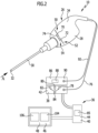
- FIGS 1 and 2 show schematically an advantageous embodiment of an imaging endoscopic device according to the invention, designated by reference number 10.
- the device 10 is used for the endoscopic examination of an examination object 12 in order to examine objects present in it, of which Figure 5 an example of an object 14 shows.
- Several objects to be imaged can be provided and, in this case, can be examined simultaneously.
- the use of the device 10 is illustrated using the example of a surgical procedure, although the present invention is not limited to medical applications. Endoscopic devices can also be used, for example, to check technical devices during production and maintenance.
- the device 10 includes three imaging units. Different embodiments can, as already mentioned, include more than three imaging units.
- the examination object 12 is accordingly the body 16 of a patient 18, and the object 14 is, for example, an organ 20 to be examined in the abdominal cavity 22.
- the operator of the device 10 is a surgeon 24.
- the device 10 comprises an endoscope 26, which is hand-held by the operator 24 and has a handle element 28 and a shaft 30 which is held thereon and can be inserted at least partially into the body 16.
- the shaft 30 has a distal end 32 which, when the endoscope 26 is used as intended, is attached to the endoscope Operator 24 is arranged on the side facing away from it.
- the handle element 28 comprises or forms a housing 34.
- the shaft 30 is designed to be rigid in the present case, but could also be flexible. Alternatively or additionally, it can be provided that the shaft 30 is held on the handle element 28 in a position-variable manner.
- the device 10 further comprises a data processing unit 36, which in the present case comprises two components which are coupled to one another in a signal-effective manner and are arranged in housings 38, 40.
- a data processing unit 36 which in the present case comprises two components which are coupled to one another in a signal-effective manner and are arranged in housings 38, 40.
- An evaluation unit 42 of the data processing unit 36 is accommodated in the housing 38 and a computing unit 44 is accommodated in the housing 40.
- the data processing unit 36 has a common housing which accommodates both the evaluation unit 42 and the computing unit 44 coupled to it.
- the data processing unit 36 is coupled to a display unit 46, which in particular includes an image display 48.
- the device 10 in the present case comprises three optical imaging units 50, 52 and 54.
- Each imaging unit 50, 52, 54 includes an imaging element 56, 58 or 60 mounted in the shaft 30 at the distal end 32.
- the imaging elements 56, 58, 60 can preferably be designed identically and are designed, for example, in the form of lenses.
- the imaging elements 56, 58, 60 are arranged in a planar arrangement to one another at the distal end 32 of the shaft 30, with axes 62, 64 and 66 defined by them running parallel to one another and parallel to an axis 68 defined by the shaft 30. Lens planes of the imaging elements 56, 58 and 60 coincide.
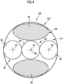
- the imaging elements 56, 58 and 60 are positioned symmetrically to one another according to an equilateral triangle on the shaft 30 ( Figure 3 , which looks axially in the proximal direction onto the distal end 32 of the shaft 30).
- Each imaging element 56, 58 and 60 defines a field of view, not shown in the drawing, in which areas of the abdominal cavity 22 and in particular the organ 20 can be arranged. Objects in the respective field of view of an imaging element 56, 58, 60 are imaged on image sensors 70, 72 and 74 of the imaging units 50, 52 and 54, respectively. Each imaging element 56, 58, 60 is associated with an image sensor 70, 72, and 74, respectively (i.e., 56-70, 58-72, and 60-74).
- Imaging elements 56, 58, 60 Light collected by the imaging elements 56, 58, 60 is guided through light-guiding elements guided in the shaft 30 and not shown in the drawing to the housing 34 of the handle element 28, in which the image sensors 70, 72, 74 are arranged. Additional imaging elements may be provided (not shown) to image light onto one of the image sensors 70, 72, 74.
- image sensors are positioned directly in the shaft 30, for example directly proximal to the imaging elements 56, 58, 60, whereby light-guiding elements can be saved.
- the image sensors 70, 72, 74 are coupled to the evaluation unit 42 via a signal line 76.
- a respective image data set 78, 80 or 82 provided by an image sensor 70, 72, 74 can be preprocessed by an evaluation element 84 of the evaluation unit 42 (schematically in Figure 2 shown).
- the image data sets 78, 80 and 82 and/or preprocessed information can be fed to a computing element 85 of the computing unit 44.
- the device 10 includes an illumination unit 86 for illuminating the scene inside the body to improve the imaging properties of the device 10.
- the lighting unit 86 includes a light source 88, which in the present case is accommodated in a housing 90 external to the endoscope 26.
- a light line 92 is guided from the housing 90 to the housing 34 of the endoscope 26.
- Three lighting elements 94, 96 and 98 are coupled to the light guide 92, which in the present case are designed as light-guiding elements in the form of glass fiber bundles.
- the lighting elements 94, 96, 98 are guided from the housing 34 through the shaft 30 and extend to the distal end 32.
- the lighting elements 94, 96, 98 are arranged symmetrically to one another according to an equilateral triangle (relative to a proximal viewing direction of the distal end 32). Furthermore, there is a symmetry in the arrangement of the lighting elements 94, 96, 98 in relation to the imaging elements 56, 58 and 60. One lighting element 94, 96, 98 is diametrically opposed to one of the imaging elements 56, 58 and 60 with respect to the axis 68 of the shaft 30 arranged opposite each other.
- the scene inside the body is illuminated as evenly as possible.
- the arrangement of the lighting elements 94, 96, 98 distally radially on the outside with respect to the imaging elements 56, 58 and 60 proves to be advantageous for avoiding reflections on the objects to be visualized.
- an endoscope 100 designed differently than the endoscope 26 can be provided, the shaft 102 of which is in Figure 4 in one of the Figure 3 is shown accordingly.
- the imaging elements 56, 58, 60 are positioned collinearly, with their axes 62, 64 and 66 running parallel to one another.
- the axis of the central imaging element coincides with the axis 68 of the shaft 102.
- the lighting unit 86 includes two lighting elements 94, 96, which are positioned laterally next to the three-array of the imaging elements 56, 58 and 60.
- the image sensors 70, 72 and 74 can be designed differently.
- the image sensors 70 and 72 are identical and designed as monochrome sensors and specifically as grayscale sensors.
- the image sensors 70, 72 can accordingly achieve a comparatively high resolution.
- the image sensor 74 can differ from the image sensors 70, 72 in the device 10 in terms of resolution and/or spectral sensitivity.
- the image sensor 74 is, for example, a color image sensor for color image representation, for example in RGB format.
- the data processing unit 36 is designed and programmed in such a way that it creates a stereo image 104 based on the image data sets 78, 80 from the image sensors 70 and 72, respectively.
- the stereo image 104 can be displayed on the display unit 46 and shows the surgeon 24 the scene in the abdominal cavity 22 in order to make it easier for him to guide the endoscope 26.
- the data processing unit 36 is designed and programmed in such a way that it analyzes the image data sets 78, 80 and 82 for corresponding (so-called homologous) image points and determines corresponding image points in the image data sets 78, 80 and 82. In this way, it is possible for the data processing unit 36 with high precision to exclude any ambiguities that can occur in the case of only two image data sets, taking into account a third image data set.
- the data processing unit 36 can create a 3D surface data set of imaged objects, for example the organ 20.
- a 3D image 106 of the 3D data set can be displayed on the display unit 46. It is also possible to overlay the 3D image 106 with the stereo image 104.
- the analysis of the image data sets 78, 80 and 82 can be carried out in particular in real time at sub-second intervals.
- the continuous analysis of the image data sets 78, 80, 82 allows the data processing unit 36 to determine changes in position and/or shape of the organ 20 in a time-dependent manner.
- the organ 20 can accordingly be tracked by the data processing unit 36, with the surface of the organ 20 being reconstructed almost in real time through continuous analysis of the image data sets 78, 80, 82.
- This increases the usefulness and user-friendliness of the device 10 for the surgeon 24 enormous.
- the operator 24 has additional information that is not available with conventional endoscopic devices.
- the device 10 can also have at least one tool 108, which in the present case is designed as a surgical instrument 110.
- a label 112 can be provided on the instrument 110.
- the marking 112 comprises a plurality of coaxial rings 114 which are arranged axially spaced apart from one another on a shaft 116 of the instrument 110.
- the data processing unit 36 can identify the instrument 110 based on the identification 112 and, like the organ 20, track it as an observed object.
Landscapes
- Health & Medical Sciences (AREA)
- Life Sciences & Earth Sciences (AREA)
- Surgery (AREA)
- Physics & Mathematics (AREA)
- Optics & Photonics (AREA)
- General Health & Medical Sciences (AREA)
- Radiology & Medical Imaging (AREA)
- Animal Behavior & Ethology (AREA)
- Veterinary Medicine (AREA)
- Engineering & Computer Science (AREA)
- Biomedical Technology (AREA)
- Heart & Thoracic Surgery (AREA)
- Medical Informatics (AREA)
- Nuclear Medicine, Radiotherapy & Molecular Imaging (AREA)
- Biophysics (AREA)
- Molecular Biology (AREA)
- Public Health (AREA)
- Pathology (AREA)
- Astronomy & Astrophysics (AREA)
- General Physics & Mathematics (AREA)
- Endoscopes (AREA)
- Instruments For Viewing The Inside Of Hollow Bodies (AREA)
Applications Claiming Priority (2)
| Application Number | Priority Date | Filing Date | Title |
|---|---|---|---|
| DE102016113000.1A DE102016113000A1 (de) | 2016-07-14 | 2016-07-14 | Endoskopische Vorrichtung und Verfahren zur endoskopischen Untersuchung |
| PCT/EP2017/067195 WO2018011106A2 (de) | 2016-07-14 | 2017-07-10 | Endoskopische vorrichtung und verfahren zur endoskopischen untersuchung |
Publications (2)
| Publication Number | Publication Date |
|---|---|
| EP3484338A2 EP3484338A2 (de) | 2019-05-22 |
| EP3484338B1 true EP3484338B1 (de) | 2024-02-14 |
Family
ID=59366415
Family Applications (1)
| Application Number | Title | Priority Date | Filing Date |
|---|---|---|---|
| EP17740713.7A Active EP3484338B1 (de) | 2016-07-14 | 2017-07-10 | Endoskopische vorrichtung und verfahren zur endoskopischen untersuchung |
Country Status (7)
| Country | Link |
|---|---|
| US (1) | US11213189B2 (enExample) |
| EP (1) | EP3484338B1 (enExample) |
| JP (2) | JP2019521778A (enExample) |
| CN (1) | CN109561810B (enExample) |
| DE (1) | DE102016113000A1 (enExample) |
| ES (1) | ES2977087T3 (enExample) |
| WO (1) | WO2018011106A2 (enExample) |
Cited By (1)
| Publication number | Priority date | Publication date | Assignee | Title |
|---|---|---|---|---|
| US12266126B2 (en) | 2021-07-27 | 2025-04-01 | Karl Storz Se & Co. Kg | Measuring method and a measuring device for measuring and determining the size and dimension of structures in scene |
Families Citing this family (11)
| Publication number | Priority date | Publication date | Assignee | Title |
|---|---|---|---|---|
| JP7048628B2 (ja) | 2016-11-28 | 2022-04-05 | アダプティブエンドウ エルエルシー | 分離可能使い捨てシャフト付き内視鏡 |
| DE102019100821A1 (de) | 2019-01-14 | 2020-07-16 | Lufthansa Technik Aktiengesellschaft | Boroskop zur optischen Inspektion von Gasturbinen |
| FR3098929B1 (fr) * | 2019-07-16 | 2021-06-18 | Yellowscan | Procédé de détermination de paramètres d'étalonnage extrinseques d'un système de mesure |
| WO2021102217A1 (en) * | 2019-11-22 | 2021-05-27 | Convergascent Llc | Utilization of multiple imagers and computational photography in endoscopy |
| USD1018844S1 (en) | 2020-01-09 | 2024-03-19 | Adaptivendo Llc | Endoscope handle |
| CN111952327A (zh) * | 2020-08-14 | 2020-11-17 | 北京高芯惠通医疗科技有限公司 | 一种用于医用内窥镜的cmos图像传感器芯片及设计方法 |
| USD1051380S1 (en) | 2020-11-17 | 2024-11-12 | Adaptivendo Llc | Endoscope handle |
| USD1070082S1 (en) | 2021-04-29 | 2025-04-08 | Adaptivendo Llc | Endoscope handle |
| USD1031035S1 (en) | 2021-04-29 | 2024-06-11 | Adaptivendo Llc | Endoscope handle |
| USD1066659S1 (en) | 2021-09-24 | 2025-03-11 | Adaptivendo Llc | Endoscope handle |
| DE102022110231A1 (de) | 2022-04-26 | 2023-10-26 | Olympus Winter & Ibe Gmbh | Verfahren, Softwareprogramm und System zum Erfassen von Bildunregelmäßigkeiten in von einem videoendoskopischen Instrument erzeugten Bildern |
Citations (3)
| Publication number | Priority date | Publication date | Assignee | Title |
|---|---|---|---|---|
| US20110228049A1 (en) * | 2010-03-12 | 2011-09-22 | Yuri Kazakevich | Stereoscopic visualization system |
| DE102011087357A1 (de) * | 2011-11-29 | 2013-05-29 | Karl Storz Gmbh & Co. Kg | Aktualisierung von präoperativ aufgenommenen 3D-Bilddaten eines Körpers |
| DE102016109173A1 (de) * | 2015-11-19 | 2017-05-24 | Aesculap Ag | Medizintechnische Koordinatenmessvorrichtung und medizintechnisches Koordinatenmessverfahren |
Family Cites Families (39)
| Publication number | Priority date | Publication date | Assignee | Title |
|---|---|---|---|---|
| US5836869A (en) * | 1994-12-13 | 1998-11-17 | Olympus Optical Co., Ltd. | Image tracking endoscope system |
| US6396873B1 (en) * | 1999-02-25 | 2002-05-28 | Envision Advanced Medical Systems | Optical device |
| JP3827912B2 (ja) * | 2000-03-31 | 2006-09-27 | 山本 和彦 | 全方向ステレオ画像撮影装置及びステレオ画像撮影装置 |
| IL135571A0 (en) * | 2000-04-10 | 2001-05-20 | Doron Adler | Minimal invasive surgery imaging system |
| JP3841630B2 (ja) | 2000-08-29 | 2006-11-01 | オリンパス株式会社 | 画像取り扱い装置 |
| US6614595B2 (en) * | 2001-02-16 | 2003-09-02 | Olympus Optical Co., Ltd. | Stereo endoscope |
| US6584339B2 (en) | 2001-06-27 | 2003-06-24 | Vanderbilt University | Method and apparatus for collecting and processing physical space data for use while performing image-guided surgery |
| US6974373B2 (en) | 2002-08-02 | 2005-12-13 | Geissler Technologies, Llc | Apparatus and methods for the volumetric and dimensional measurement of livestock |
| JP4383188B2 (ja) * | 2003-04-01 | 2009-12-16 | オリンパス株式会社 | 立体観察システム |
| JP2005087468A (ja) * | 2003-09-17 | 2005-04-07 | Shoji Kawahito | 距離画像計測機能を有する撮像装置及び内視鏡装置 |
| JPWO2005046462A1 (ja) * | 2003-11-14 | 2007-05-24 | 株式会社アプリコット | 内視鏡装置及びこれを用いた撮影方法 |
| US20060020167A1 (en) | 2004-06-30 | 2006-01-26 | James Sitzmann | Medical devices for minimally invasive surgeries and other internal procedures |
| DE102007018641B8 (de) | 2007-04-19 | 2009-10-08 | Carl Zeiss Surgical Gmbh | Navigationssystem für Gehirnoperationen |
| US8929645B2 (en) | 2007-04-24 | 2015-01-06 | 21 Ct, Inc. | Method and system for fast dense stereoscopic ranging |
| DE102008018636B4 (de) * | 2008-04-11 | 2011-01-05 | Storz Endoskop Produktions Gmbh | Vorrichtung und Verfahren zur endoskopischen 3D-Datenerfassung |
| US8803955B2 (en) * | 2008-04-26 | 2014-08-12 | Intuitive Surgical Operations, Inc. | Augmented stereoscopic visualization for a surgical robot using a camera unit with a modified prism |
| US9526586B2 (en) * | 2013-08-12 | 2016-12-27 | Z Microsystems, Inc. | Software tools platform for medical environments |
| WO2011020505A1 (en) | 2009-08-20 | 2011-02-24 | Brainlab Ag | Integrated surgical device combining instrument; tracking system and navigation system |
| US20110251456A1 (en) * | 2009-10-01 | 2011-10-13 | Jacobsen Stephen C | Method and Apparatus For Viewing A Body Cavity |
| DE102009046108B4 (de) | 2009-10-28 | 2022-06-09 | pmdtechnologies ag | Kamerasystem |
| JP5458380B2 (ja) * | 2009-11-09 | 2014-04-02 | 国立大学法人岩手大学 | 画像処理装置及び方法 |
| CA2743187A1 (en) * | 2010-06-11 | 2011-12-11 | The Hospital For Sick Children | Folding endoscope and method of using the same |
| DE102010041870A1 (de) * | 2010-10-01 | 2012-04-05 | Olympus Winter & Ibe Gmbh | Verfahren und System zur horizontrichtigen stereoskopischen Bildverarbeitung |
| WO2012078126A1 (en) | 2010-12-08 | 2012-06-14 | Thomson Licensing | System and method for trinocular depth acquisition with triangular sensor |
| KR101591493B1 (ko) * | 2011-03-29 | 2016-02-03 | 퀄컴 인코포레이티드 | 각각의 사용자의 시점에 대해 공유된 디지털 인터페이스들의 렌더링을 위한 시스템 |
| DE102011114541A1 (de) | 2011-09-30 | 2013-04-04 | Lufthansa Technik Ag | Endoskopiesystem und korrespondierendesVerfahren zur Untersuchung von Gasturbinen |
| DE102011084920B4 (de) | 2011-10-20 | 2014-03-20 | Digital Endoscopy OEM GmbH | Endoskopiesystem, steuersystem und verwendung eines steuersystems bei einem endoskopiesystem |
| WO2013071437A1 (en) * | 2011-11-15 | 2013-05-23 | Macdonald Dettwiler & Associates Inc. | Method of real-time tracking of moving/flexible surfaces |
| WO2013155388A1 (en) | 2012-04-12 | 2013-10-17 | University Of Florida Research Foundation, Inc. | Ambiguity-free optical tracking system |
| US9801551B2 (en) * | 2012-07-20 | 2017-10-31 | Intuitive Sugical Operations, Inc. | Annular vision system |
| JP6146981B2 (ja) * | 2012-10-16 | 2017-06-14 | オリンパス株式会社 | 観察装置、観察支援装置及びプログラム |
| US9135710B2 (en) | 2012-11-30 | 2015-09-15 | Adobe Systems Incorporated | Depth map stereo correspondence techniques |
| DE102013200898A1 (de) | 2013-01-21 | 2014-07-24 | Siemens Aktiengesellschaft | Endoskop, insbesondere für die minimal-invasive Chirurgie |
| JP2014185901A (ja) * | 2013-03-22 | 2014-10-02 | 3D Media Co Ltd | 3次元物体認識装置 |
| US20140375784A1 (en) | 2013-06-21 | 2014-12-25 | Omnivision Technologies, Inc. | Image Sensor With Integrated Orientation Indicator |
| DE102013112375A1 (de) | 2013-11-11 | 2015-05-13 | Aesculap Ag | Chirurgische Referenzierungsvorrichtung, chirurgisches Navigationssystem und Verfahren |
| DE102014104800A1 (de) | 2014-04-03 | 2015-10-08 | Aesculap Ag | Medizinische Befestigungseinrichtung sowie Referenzierungsvorrichtung und medizinisches Instrumentarium |
| US10898271B2 (en) | 2015-06-29 | 2021-01-26 | Medtronic Navigation, Inc. | Method and apparatus for identification of multiple navigated instruments |
| CN105627926B (zh) * | 2016-01-22 | 2017-02-08 | 尹兴 | 四像机组平面阵列特征点三维测量系统及测量方法 |
-
2016
- 2016-07-14 DE DE102016113000.1A patent/DE102016113000A1/de active Pending
-
2017
- 2017-07-10 WO PCT/EP2017/067195 patent/WO2018011106A2/de not_active Ceased
- 2017-07-10 CN CN201780042930.5A patent/CN109561810B/zh active Active
- 2017-07-10 JP JP2019500630A patent/JP2019521778A/ja active Pending
- 2017-07-10 ES ES17740713T patent/ES2977087T3/es active Active
- 2017-07-10 EP EP17740713.7A patent/EP3484338B1/de active Active
-
2019
- 2019-01-10 US US16/244,187 patent/US11213189B2/en active Active
-
2022
- 2022-02-10 JP JP2022019942A patent/JP2022062231A/ja active Pending
Patent Citations (3)
| Publication number | Priority date | Publication date | Assignee | Title |
|---|---|---|---|---|
| US20110228049A1 (en) * | 2010-03-12 | 2011-09-22 | Yuri Kazakevich | Stereoscopic visualization system |
| DE102011087357A1 (de) * | 2011-11-29 | 2013-05-29 | Karl Storz Gmbh & Co. Kg | Aktualisierung von präoperativ aufgenommenen 3D-Bilddaten eines Körpers |
| DE102016109173A1 (de) * | 2015-11-19 | 2017-05-24 | Aesculap Ag | Medizintechnische Koordinatenmessvorrichtung und medizintechnisches Koordinatenmessverfahren |
Cited By (1)
| Publication number | Priority date | Publication date | Assignee | Title |
|---|---|---|---|---|
| US12266126B2 (en) | 2021-07-27 | 2025-04-01 | Karl Storz Se & Co. Kg | Measuring method and a measuring device for measuring and determining the size and dimension of structures in scene |
Also Published As
| Publication number | Publication date |
|---|---|
| WO2018011106A3 (de) | 2018-03-08 |
| ES2977087T3 (es) | 2024-08-19 |
| US11213189B2 (en) | 2022-01-04 |
| JP2022062231A (ja) | 2022-04-19 |
| US20190142250A1 (en) | 2019-05-16 |
| CN109561810B (zh) | 2022-05-24 |
| JP2019521778A (ja) | 2019-08-08 |
| DE102016113000A1 (de) | 2018-01-18 |
| CN109561810A (zh) | 2019-04-02 |
| WO2018011106A2 (de) | 2018-01-18 |
| EP3484338A2 (de) | 2019-05-22 |
Similar Documents
| Publication | Publication Date | Title |
|---|---|---|
| EP3484338B1 (de) | Endoskopische vorrichtung und verfahren zur endoskopischen untersuchung | |
| DE19961971B4 (de) | Vorrichtung zum sicheren automatischen Nachführen eines Endoskops und Verfolgen eines Instruments | |
| EP0975257B1 (de) | Endoskopisches system | |
| EP1713387B1 (de) | Verfahren und vorrichtung zum erstellen zumindest eines ausschnitts eines virtuellen 3d-modells eines körperinnenraums | |
| EP3363358B1 (de) | Vorrichtung zum festlegen und wiederauffinden eines bezugspunkts während eines chirurgischen eingriffs | |
| DE102009010263B4 (de) | Verfahren zur Navigation eines endoskopischen Instruments bei der technischen Endoskopie und zugehörige Vorrichtung | |
| DE112016006299T5 (de) | Medizinische Sicherheitssteuerungsvorrichtung, medizinisches Sicherheitssteuerungsverfahren und medizinisches Unterstützungssystem | |
| WO2011023339A1 (de) | Endoskop und verfahren zu dessen verwendung | |
| DE102007054450A1 (de) | Vorrichtung zur Bereitstellung von Bildern für einen Operateur | |
| DE102014103044A1 (de) | Chirurgisches Assistenzsystem | |
| DE102014007908A1 (de) | Chirurgie-System | |
| DE102014010350A1 (de) | Augenchirurgiesystem | |
| DE102013217112A1 (de) | Bildverarbeitungsvorrichtung, bildverarbeitungsverfahren und programm | |
| DE112017005662T5 (de) | Gelenkantriebsaktuator und medizinisches system | |
| DE4241938A1 (de) | Endoskop insbesondere mit Stereo-Seitblickoptik | |
| DE102010041847A1 (de) | Sensoreinheit für ein Stereoendoskop und Stereoendoskopiesystem | |
| DE102018124432A1 (de) | System und Verfahren zum Halten einer Bildwiedergabevorrichtung | |
| DE102016117263B4 (de) | Optisches Beobachtungsgerätsystem | |
| WO2018007091A1 (de) | Vorrichtung zur bildgebung in einem operationssaal | |
| WO2019215061A1 (de) | Vorrichtung und verfahren zur bildgebung bei der implantation von retinaimplantaten | |
| DE102022126824A1 (de) | Verfahren zum Überlagern von Überlagerungsaufnahmeinformationen mit einem Livebild und eine entsprechende Vorrichtung | |
| EP4124283A1 (de) | Messverfahren und eine messvorrichtung | |
| DE102019130369A1 (de) | Kamerasystem zum Verordnen eines Detailbilds einer Hautstelle eines Patienten sowie Online-Dermatoskop | |
| DE102015000383B4 (de) | Chirurgisches Mikroskop | |
| DE102011082444A1 (de) | Verfahren und Vorrichtung zur bildunterstützten Navigation eines endoskopischen Instruments |
Legal Events
| Date | Code | Title | Description |
|---|---|---|---|
| STAA | Information on the status of an ep patent application or granted ep patent |
Free format text: STATUS: UNKNOWN |
|
| STAA | Information on the status of an ep patent application or granted ep patent |
Free format text: STATUS: THE INTERNATIONAL PUBLICATION HAS BEEN MADE |
|
| PUAI | Public reference made under article 153(3) epc to a published international application that has entered the european phase |
Free format text: ORIGINAL CODE: 0009012 |
|
| STAA | Information on the status of an ep patent application or granted ep patent |
Free format text: STATUS: REQUEST FOR EXAMINATION WAS MADE |
|
| 17P | Request for examination filed |
Effective date: 20190103 |
|
| AK | Designated contracting states |
Kind code of ref document: A2 Designated state(s): AL AT BE BG CH CY CZ DE DK EE ES FI FR GB GR HR HU IE IS IT LI LT LU LV MC MK MT NL NO PL PT RO RS SE SI SK SM TR |
|
| AX | Request for extension of the european patent |
Extension state: BA ME |
|
| DAV | Request for validation of the european patent (deleted) | ||
| DAX | Request for extension of the european patent (deleted) | ||
| STAA | Information on the status of an ep patent application or granted ep patent |
Free format text: STATUS: EXAMINATION IS IN PROGRESS |
|
| 17Q | First examination report despatched |
Effective date: 20191105 |
|
| GRAP | Despatch of communication of intention to grant a patent |
Free format text: ORIGINAL CODE: EPIDOSNIGR1 |
|
| STAA | Information on the status of an ep patent application or granted ep patent |
Free format text: STATUS: GRANT OF PATENT IS INTENDED |
|
| INTG | Intention to grant announced |
Effective date: 20230822 |
|
| P01 | Opt-out of the competence of the unified patent court (upc) registered |
Effective date: 20231024 |
|
| GRAS | Grant fee paid |
Free format text: ORIGINAL CODE: EPIDOSNIGR3 |
|
| GRAA | (expected) grant |
Free format text: ORIGINAL CODE: 0009210 |
|
| STAA | Information on the status of an ep patent application or granted ep patent |
Free format text: STATUS: THE PATENT HAS BEEN GRANTED |
|
| AK | Designated contracting states |
Kind code of ref document: B1 Designated state(s): AL AT BE BG CH CY CZ DE DK EE ES FI FR GB GR HR HU IE IS IT LI LT LU LV MC MK MT NL NO PL PT RO RS SE SI SK SM TR |
|
| REG | Reference to a national code |
Ref country code: GB Ref legal event code: FG4D Free format text: NOT ENGLISH |
|
| REG | Reference to a national code |
Ref country code: CH Ref legal event code: EP |
|
| REG | Reference to a national code |
Ref country code: DE Ref legal event code: R096 Ref document number: 502017015830 Country of ref document: DE |
|
| REG | Reference to a national code |
Ref country code: IE Ref legal event code: FG4D Free format text: LANGUAGE OF EP DOCUMENT: GERMAN |
|
| REG | Reference to a national code |
Ref country code: LT Ref legal event code: MG9D |
|
| REG | Reference to a national code |
Ref country code: NL Ref legal event code: MP Effective date: 20240214 |
|
| PG25 | Lapsed in a contracting state [announced via postgrant information from national office to epo] |
Ref country code: IS Free format text: LAPSE BECAUSE OF FAILURE TO SUBMIT A TRANSLATION OF THE DESCRIPTION OR TO PAY THE FEE WITHIN THE PRESCRIBED TIME-LIMIT Effective date: 20240614 |
|
| PG25 | Lapsed in a contracting state [announced via postgrant information from national office to epo] |
Ref country code: LT Free format text: LAPSE BECAUSE OF FAILURE TO SUBMIT A TRANSLATION OF THE DESCRIPTION OR TO PAY THE FEE WITHIN THE PRESCRIBED TIME-LIMIT Effective date: 20240214 |
|
| PG25 | Lapsed in a contracting state [announced via postgrant information from national office to epo] |
Ref country code: GR Free format text: LAPSE BECAUSE OF FAILURE TO SUBMIT A TRANSLATION OF THE DESCRIPTION OR TO PAY THE FEE WITHIN THE PRESCRIBED TIME-LIMIT Effective date: 20240515 |
|
| PG25 | Lapsed in a contracting state [announced via postgrant information from national office to epo] |
Ref country code: HR Free format text: LAPSE BECAUSE OF FAILURE TO SUBMIT A TRANSLATION OF THE DESCRIPTION OR TO PAY THE FEE WITHIN THE PRESCRIBED TIME-LIMIT Effective date: 20240214 Ref country code: RS Free format text: LAPSE BECAUSE OF FAILURE TO SUBMIT A TRANSLATION OF THE DESCRIPTION OR TO PAY THE FEE WITHIN THE PRESCRIBED TIME-LIMIT Effective date: 20240514 Ref country code: NL Free format text: LAPSE BECAUSE OF FAILURE TO SUBMIT A TRANSLATION OF THE DESCRIPTION OR TO PAY THE FEE WITHIN THE PRESCRIBED TIME-LIMIT Effective date: 20240214 |
|
| PG25 | Lapsed in a contracting state [announced via postgrant information from national office to epo] |
Ref country code: RS Free format text: LAPSE BECAUSE OF FAILURE TO SUBMIT A TRANSLATION OF THE DESCRIPTION OR TO PAY THE FEE WITHIN THE PRESCRIBED TIME-LIMIT Effective date: 20240514 Ref country code: NO Free format text: LAPSE BECAUSE OF FAILURE TO SUBMIT A TRANSLATION OF THE DESCRIPTION OR TO PAY THE FEE WITHIN THE PRESCRIBED TIME-LIMIT Effective date: 20240514 Ref country code: NL Free format text: LAPSE BECAUSE OF FAILURE TO SUBMIT A TRANSLATION OF THE DESCRIPTION OR TO PAY THE FEE WITHIN THE PRESCRIBED TIME-LIMIT Effective date: 20240214 Ref country code: LT Free format text: LAPSE BECAUSE OF FAILURE TO SUBMIT A TRANSLATION OF THE DESCRIPTION OR TO PAY THE FEE WITHIN THE PRESCRIBED TIME-LIMIT Effective date: 20240214 Ref country code: IS Free format text: LAPSE BECAUSE OF FAILURE TO SUBMIT A TRANSLATION OF THE DESCRIPTION OR TO PAY THE FEE WITHIN THE PRESCRIBED TIME-LIMIT Effective date: 20240614 Ref country code: HR Free format text: LAPSE BECAUSE OF FAILURE TO SUBMIT A TRANSLATION OF THE DESCRIPTION OR TO PAY THE FEE WITHIN THE PRESCRIBED TIME-LIMIT Effective date: 20240214 Ref country code: GR Free format text: LAPSE BECAUSE OF FAILURE TO SUBMIT A TRANSLATION OF THE DESCRIPTION OR TO PAY THE FEE WITHIN THE PRESCRIBED TIME-LIMIT Effective date: 20240515 Ref country code: FI Free format text: LAPSE BECAUSE OF FAILURE TO SUBMIT A TRANSLATION OF THE DESCRIPTION OR TO PAY THE FEE WITHIN THE PRESCRIBED TIME-LIMIT Effective date: 20240214 Ref country code: BG Free format text: LAPSE BECAUSE OF FAILURE TO SUBMIT A TRANSLATION OF THE DESCRIPTION OR TO PAY THE FEE WITHIN THE PRESCRIBED TIME-LIMIT Effective date: 20240214 |
|
| PG25 | Lapsed in a contracting state [announced via postgrant information from national office to epo] |
Ref country code: PT Free format text: LAPSE BECAUSE OF FAILURE TO SUBMIT A TRANSLATION OF THE DESCRIPTION OR TO PAY THE FEE WITHIN THE PRESCRIBED TIME-LIMIT Effective date: 20240614 Ref country code: PL Free format text: LAPSE BECAUSE OF FAILURE TO SUBMIT A TRANSLATION OF THE DESCRIPTION OR TO PAY THE FEE WITHIN THE PRESCRIBED TIME-LIMIT Effective date: 20240214 |
|
| REG | Reference to a national code |
Ref country code: ES Ref legal event code: FG2A Ref document number: 2977087 Country of ref document: ES Kind code of ref document: T3 Effective date: 20240819 |
|
| PG25 | Lapsed in a contracting state [announced via postgrant information from national office to epo] |
Ref country code: SE Free format text: LAPSE BECAUSE OF FAILURE TO SUBMIT A TRANSLATION OF THE DESCRIPTION OR TO PAY THE FEE WITHIN THE PRESCRIBED TIME-LIMIT Effective date: 20240214 Ref country code: PT Free format text: LAPSE BECAUSE OF FAILURE TO SUBMIT A TRANSLATION OF THE DESCRIPTION OR TO PAY THE FEE WITHIN THE PRESCRIBED TIME-LIMIT Effective date: 20240614 Ref country code: PL Free format text: LAPSE BECAUSE OF FAILURE TO SUBMIT A TRANSLATION OF THE DESCRIPTION OR TO PAY THE FEE WITHIN THE PRESCRIBED TIME-LIMIT Effective date: 20240214 Ref country code: LV Free format text: LAPSE BECAUSE OF FAILURE TO SUBMIT A TRANSLATION OF THE DESCRIPTION OR TO PAY THE FEE WITHIN THE PRESCRIBED TIME-LIMIT Effective date: 20240214 |
|
| PG25 | Lapsed in a contracting state [announced via postgrant information from national office to epo] |
Ref country code: DK Free format text: LAPSE BECAUSE OF FAILURE TO SUBMIT A TRANSLATION OF THE DESCRIPTION OR TO PAY THE FEE WITHIN THE PRESCRIBED TIME-LIMIT Effective date: 20240214 |
|
| PG25 | Lapsed in a contracting state [announced via postgrant information from national office to epo] |
Ref country code: SM Free format text: LAPSE BECAUSE OF FAILURE TO SUBMIT A TRANSLATION OF THE DESCRIPTION OR TO PAY THE FEE WITHIN THE PRESCRIBED TIME-LIMIT Effective date: 20240214 |
|
| PG25 | Lapsed in a contracting state [announced via postgrant information from national office to epo] |
Ref country code: CZ Free format text: LAPSE BECAUSE OF FAILURE TO SUBMIT A TRANSLATION OF THE DESCRIPTION OR TO PAY THE FEE WITHIN THE PRESCRIBED TIME-LIMIT Effective date: 20240214 Ref country code: EE Free format text: LAPSE BECAUSE OF FAILURE TO SUBMIT A TRANSLATION OF THE DESCRIPTION OR TO PAY THE FEE WITHIN THE PRESCRIBED TIME-LIMIT Effective date: 20240214 |
|
| PG25 | Lapsed in a contracting state [announced via postgrant information from national office to epo] |
Ref country code: SK Free format text: LAPSE BECAUSE OF FAILURE TO SUBMIT A TRANSLATION OF THE DESCRIPTION OR TO PAY THE FEE WITHIN THE PRESCRIBED TIME-LIMIT Effective date: 20240214 |
|
| PG25 | Lapsed in a contracting state [announced via postgrant information from national office to epo] |
Ref country code: SM Free format text: LAPSE BECAUSE OF FAILURE TO SUBMIT A TRANSLATION OF THE DESCRIPTION OR TO PAY THE FEE WITHIN THE PRESCRIBED TIME-LIMIT Effective date: 20240214 Ref country code: SK Free format text: LAPSE BECAUSE OF FAILURE TO SUBMIT A TRANSLATION OF THE DESCRIPTION OR TO PAY THE FEE WITHIN THE PRESCRIBED TIME-LIMIT Effective date: 20240214 Ref country code: RO Free format text: LAPSE BECAUSE OF FAILURE TO SUBMIT A TRANSLATION OF THE DESCRIPTION OR TO PAY THE FEE WITHIN THE PRESCRIBED TIME-LIMIT Effective date: 20240214 Ref country code: EE Free format text: LAPSE BECAUSE OF FAILURE TO SUBMIT A TRANSLATION OF THE DESCRIPTION OR TO PAY THE FEE WITHIN THE PRESCRIBED TIME-LIMIT Effective date: 20240214 Ref country code: DK Free format text: LAPSE BECAUSE OF FAILURE TO SUBMIT A TRANSLATION OF THE DESCRIPTION OR TO PAY THE FEE WITHIN THE PRESCRIBED TIME-LIMIT Effective date: 20240214 Ref country code: CZ Free format text: LAPSE BECAUSE OF FAILURE TO SUBMIT A TRANSLATION OF THE DESCRIPTION OR TO PAY THE FEE WITHIN THE PRESCRIBED TIME-LIMIT Effective date: 20240214 |
|
| REG | Reference to a national code |
Ref country code: DE Ref legal event code: R097 Ref document number: 502017015830 Country of ref document: DE |
|
| PLBE | No opposition filed within time limit |
Free format text: ORIGINAL CODE: 0009261 |
|
| STAA | Information on the status of an ep patent application or granted ep patent |
Free format text: STATUS: NO OPPOSITION FILED WITHIN TIME LIMIT |
|
| 26N | No opposition filed |
Effective date: 20241115 |
|
| PG25 | Lapsed in a contracting state [announced via postgrant information from national office to epo] |
Ref country code: MC Free format text: LAPSE BECAUSE OF FAILURE TO SUBMIT A TRANSLATION OF THE DESCRIPTION OR TO PAY THE FEE WITHIN THE PRESCRIBED TIME-LIMIT Effective date: 20240214 |
|
| REG | Reference to a national code |
Ref country code: CH Ref legal event code: PL |
|
| PG25 | Lapsed in a contracting state [announced via postgrant information from national office to epo] |
Ref country code: LU Free format text: LAPSE BECAUSE OF NON-PAYMENT OF DUE FEES Effective date: 20240710 |
|
| PG25 | Lapsed in a contracting state [announced via postgrant information from national office to epo] |
Ref country code: LU Free format text: LAPSE BECAUSE OF NON-PAYMENT OF DUE FEES Effective date: 20240710 |
|
| PG25 | Lapsed in a contracting state [announced via postgrant information from national office to epo] |
Ref country code: SI Free format text: LAPSE BECAUSE OF FAILURE TO SUBMIT A TRANSLATION OF THE DESCRIPTION OR TO PAY THE FEE WITHIN THE PRESCRIBED TIME-LIMIT Effective date: 20240214 Ref country code: CH Free format text: LAPSE BECAUSE OF NON-PAYMENT OF DUE FEES Effective date: 20240731 Ref country code: BE Free format text: LAPSE BECAUSE OF NON-PAYMENT OF DUE FEES Effective date: 20240731 |
|
| REG | Reference to a national code |
Ref country code: BE Ref legal event code: MM Effective date: 20240731 |
|
| PG25 | Lapsed in a contracting state [announced via postgrant information from national office to epo] |
Ref country code: IE Free format text: LAPSE BECAUSE OF NON-PAYMENT OF DUE FEES Effective date: 20240710 |
|
| REG | Reference to a national code |
Ref country code: AT Ref legal event code: MM01 Ref document number: 1656295 Country of ref document: AT Kind code of ref document: T Effective date: 20240710 |
|
| PGFP | Annual fee paid to national office [announced via postgrant information from national office to epo] |
Ref country code: ES Payment date: 20250819 Year of fee payment: 9 |
|
| PGFP | Annual fee paid to national office [announced via postgrant information from national office to epo] |
Ref country code: DE Payment date: 20250722 Year of fee payment: 9 |
|
| PGFP | Annual fee paid to national office [announced via postgrant information from national office to epo] |
Ref country code: IT Payment date: 20250731 Year of fee payment: 9 |
|
| PGFP | Annual fee paid to national office [announced via postgrant information from national office to epo] |
Ref country code: GB Payment date: 20250724 Year of fee payment: 9 |
|
| PG25 | Lapsed in a contracting state [announced via postgrant information from national office to epo] |
Ref country code: AT Free format text: LAPSE BECAUSE OF NON-PAYMENT OF DUE FEES Effective date: 20240710 |
|
| PGFP | Annual fee paid to national office [announced via postgrant information from national office to epo] |
Ref country code: FR Payment date: 20250723 Year of fee payment: 9 |
|
| PG25 | Lapsed in a contracting state [announced via postgrant information from national office to epo] |
Ref country code: CY Free format text: LAPSE BECAUSE OF FAILURE TO SUBMIT A TRANSLATION OF THE DESCRIPTION OR TO PAY THE FEE WITHIN THE PRESCRIBED TIME-LIMIT; INVALID AB INITIO Effective date: 20170710 |