EP3483714B1 - Electronic device and operation method therefor - Google Patents
Electronic device and operation method therefor Download PDFInfo
- Publication number
- EP3483714B1 EP3483714B1 EP17837154.8A EP17837154A EP3483714B1 EP 3483714 B1 EP3483714 B1 EP 3483714B1 EP 17837154 A EP17837154 A EP 17837154A EP 3483714 B1 EP3483714 B1 EP 3483714B1
- Authority
- EP
- European Patent Office
- Prior art keywords
- region
- touch
- electronic device
- display
- blocking region
- Prior art date
- Legal status (The legal status is an assumption and is not a legal conclusion. Google has not performed a legal analysis and makes no representation as to the accuracy of the status listed.)
- Active
Links
- 238000000034 method Methods 0.000 title claims description 125
- 230000000903 blocking effect Effects 0.000 claims description 308
- 230000008569 process Effects 0.000 claims description 56
- 230000008859 change Effects 0.000 claims description 55
- 238000012545 processing Methods 0.000 claims description 48
- 230000004044 response Effects 0.000 claims description 18
- 238000004590 computer program Methods 0.000 claims 1
- 230000006870 function Effects 0.000 description 56
- 238000004891 communication Methods 0.000 description 46
- 230000001133 acceleration Effects 0.000 description 11
- 230000007257 malfunction Effects 0.000 description 9
- 230000001413 cellular effect Effects 0.000 description 8
- 238000010586 diagram Methods 0.000 description 5
- 238000005516 engineering process Methods 0.000 description 5
- 238000005452 bending Methods 0.000 description 4
- 238000004364 calculation method Methods 0.000 description 4
- 230000000694 effects Effects 0.000 description 4
- 230000003287 optical effect Effects 0.000 description 4
- 230000005236 sound signal Effects 0.000 description 4
- 238000001914 filtration Methods 0.000 description 3
- 210000003811 finger Anatomy 0.000 description 3
- 230000007704 transition Effects 0.000 description 3
- 238000013459 approach Methods 0.000 description 2
- 239000008280 blood Substances 0.000 description 2
- 210000004369 blood Anatomy 0.000 description 2
- 238000002591 computed tomography Methods 0.000 description 2
- 230000009849 deactivation Effects 0.000 description 2
- 239000011521 glass Substances 0.000 description 2
- 230000036541 health Effects 0.000 description 2
- 238000010295 mobile communication Methods 0.000 description 2
- 238000003825 pressing Methods 0.000 description 2
- 239000000758 substrate Substances 0.000 description 2
- 230000000007 visual effect Effects 0.000 description 2
- XLYOFNOQVPJJNP-UHFFFAOYSA-N water Substances O XLYOFNOQVPJJNP-UHFFFAOYSA-N 0.000 description 2
- NCGICGYLBXGBGN-UHFFFAOYSA-N 3-morpholin-4-yl-1-oxa-3-azonia-2-azanidacyclopent-3-en-5-imine;hydrochloride Chemical compound Cl.[N-]1OC(=N)C=[N+]1N1CCOCC1 NCGICGYLBXGBGN-UHFFFAOYSA-N 0.000 description 1
- WQZGKKKJIJFFOK-GASJEMHNSA-N Glucose Natural products OC[C@H]1OC(O)[C@H](O)[C@@H](O)[C@@H]1O WQZGKKKJIJFFOK-GASJEMHNSA-N 0.000 description 1
- 238000002583 angiography Methods 0.000 description 1
- 210000003423 ankle Anatomy 0.000 description 1
- 238000013473 artificial intelligence Methods 0.000 description 1
- 239000011230 binding agent Substances 0.000 description 1
- 230000005540 biological transmission Effects 0.000 description 1
- 230000036772 blood pressure Effects 0.000 description 1
- 230000036760 body temperature Effects 0.000 description 1
- 230000010267 cellular communication Effects 0.000 description 1
- 238000006243 chemical reaction Methods 0.000 description 1
- 230000019771 cognition Effects 0.000 description 1
- 230000000295 complement effect Effects 0.000 description 1
- 230000008878 coupling Effects 0.000 description 1
- 238000010168 coupling process Methods 0.000 description 1
- 238000005859 coupling reaction Methods 0.000 description 1
- 230000001419 dependent effect Effects 0.000 description 1
- 238000013461 design Methods 0.000 description 1
- 238000001514 detection method Methods 0.000 description 1
- 230000005611 electricity Effects 0.000 description 1
- 238000002567 electromyography Methods 0.000 description 1
- 239000000446 fuel Substances 0.000 description 1
- 239000008103 glucose Substances 0.000 description 1
- 230000005484 gravity Effects 0.000 description 1
- 230000006698 induction Effects 0.000 description 1
- 238000012905 input function Methods 0.000 description 1
- 238000009434 installation Methods 0.000 description 1
- 239000004973 liquid crystal related substance Substances 0.000 description 1
- 230000007774 longterm Effects 0.000 description 1
- 238000002595 magnetic resonance imaging Methods 0.000 description 1
- 238000001646 magnetic resonance method Methods 0.000 description 1
- 238000005259 measurement Methods 0.000 description 1
- 229910044991 metal oxide Inorganic materials 0.000 description 1
- 150000004706 metal oxides Chemical class 0.000 description 1
- 238000012806 monitoring device Methods 0.000 description 1
- 239000002985 plastic film Substances 0.000 description 1
- 229920006255 plastic film Polymers 0.000 description 1
- 238000003672 processing method Methods 0.000 description 1
- 230000009467 reduction Effects 0.000 description 1
- 238000009877 rendering Methods 0.000 description 1
- 239000004065 semiconductor Substances 0.000 description 1
- 239000007787 solid Substances 0.000 description 1
- 230000003068 static effect Effects 0.000 description 1
- 230000001360 synchronised effect Effects 0.000 description 1
- 210000003813 thumb Anatomy 0.000 description 1
- 238000005406 washing Methods 0.000 description 1
- 229910052724 xenon Inorganic materials 0.000 description 1
- FHNFHKCVQCLJFQ-UHFFFAOYSA-N xenon atom Chemical compound [Xe] FHNFHKCVQCLJFQ-UHFFFAOYSA-N 0.000 description 1
Images


Classifications
-
- G—PHYSICS
- G06—COMPUTING; CALCULATING OR COUNTING
- G06F—ELECTRIC DIGITAL DATA PROCESSING
- G06F3/00—Input arrangements for transferring data to be processed into a form capable of being handled by the computer; Output arrangements for transferring data from processing unit to output unit, e.g. interface arrangements
- G06F3/01—Input arrangements or combined input and output arrangements for interaction between user and computer
- G06F3/03—Arrangements for converting the position or the displacement of a member into a coded form
- G06F3/041—Digitisers, e.g. for touch screens or touch pads, characterised by the transducing means
- G06F3/0416—Control or interface arrangements specially adapted for digitisers
- G06F3/0418—Control or interface arrangements specially adapted for digitisers for error correction or compensation, e.g. based on parallax, calibration or alignment
-
- G—PHYSICS
- G06—COMPUTING; CALCULATING OR COUNTING
- G06F—ELECTRIC DIGITAL DATA PROCESSING
- G06F3/00—Input arrangements for transferring data to be processed into a form capable of being handled by the computer; Output arrangements for transferring data from processing unit to output unit, e.g. interface arrangements
- G06F3/01—Input arrangements or combined input and output arrangements for interaction between user and computer
- G06F3/048—Interaction techniques based on graphical user interfaces [GUI]
- G06F3/0487—Interaction techniques based on graphical user interfaces [GUI] using specific features provided by the input device, e.g. functions controlled by the rotation of a mouse with dual sensing arrangements, or of the nature of the input device, e.g. tap gestures based on pressure sensed by a digitiser
- G06F3/0488—Interaction techniques based on graphical user interfaces [GUI] using specific features provided by the input device, e.g. functions controlled by the rotation of a mouse with dual sensing arrangements, or of the nature of the input device, e.g. tap gestures based on pressure sensed by a digitiser using a touch-screen or digitiser, e.g. input of commands through traced gestures
-
- G—PHYSICS
- G06—COMPUTING; CALCULATING OR COUNTING
- G06F—ELECTRIC DIGITAL DATA PROCESSING
- G06F3/00—Input arrangements for transferring data to be processed into a form capable of being handled by the computer; Output arrangements for transferring data from processing unit to output unit, e.g. interface arrangements
- G06F3/01—Input arrangements or combined input and output arrangements for interaction between user and computer
- G06F3/03—Arrangements for converting the position or the displacement of a member into a coded form
- G06F3/041—Digitisers, e.g. for touch screens or touch pads, characterised by the transducing means
- G06F3/0416—Control or interface arrangements specially adapted for digitisers
-
- G—PHYSICS
- G06—COMPUTING; CALCULATING OR COUNTING
- G06F—ELECTRIC DIGITAL DATA PROCESSING
- G06F3/00—Input arrangements for transferring data to be processed into a form capable of being handled by the computer; Output arrangements for transferring data from processing unit to output unit, e.g. interface arrangements
- G06F3/01—Input arrangements or combined input and output arrangements for interaction between user and computer
- G06F3/048—Interaction techniques based on graphical user interfaces [GUI]
- G06F3/0487—Interaction techniques based on graphical user interfaces [GUI] using specific features provided by the input device, e.g. functions controlled by the rotation of a mouse with dual sensing arrangements, or of the nature of the input device, e.g. tap gestures based on pressure sensed by a digitiser
- G06F3/0488—Interaction techniques based on graphical user interfaces [GUI] using specific features provided by the input device, e.g. functions controlled by the rotation of a mouse with dual sensing arrangements, or of the nature of the input device, e.g. tap gestures based on pressure sensed by a digitiser using a touch-screen or digitiser, e.g. input of commands through traced gestures
- G06F3/04886—Interaction techniques based on graphical user interfaces [GUI] using specific features provided by the input device, e.g. functions controlled by the rotation of a mouse with dual sensing arrangements, or of the nature of the input device, e.g. tap gestures based on pressure sensed by a digitiser using a touch-screen or digitiser, e.g. input of commands through traced gestures by partitioning the display area of the touch-screen or the surface of the digitising tablet into independently controllable areas, e.g. virtual keyboards or menus
-
- G—PHYSICS
- G06—COMPUTING; CALCULATING OR COUNTING
- G06F—ELECTRIC DIGITAL DATA PROCESSING
- G06F2203/00—Indexing scheme relating to G06F3/00 - G06F3/048
- G06F2203/041—Indexing scheme relating to G06F3/041 - G06F3/045
- G06F2203/04102—Flexible digitiser, i.e. constructional details for allowing the whole digitising part of a device to be flexed or rolled like a sheet of paper
Definitions
- Various embodiments of the present disclosure relate to a method and an apparatus for processing a touch event to prevent an unintended touch input from a user in an electronic device.
- the flexible display may refer to a display that can be freely bent and unbent
- the curved display may refer to a display that maintains a bent state of the display in consideration of a design of an electronic device.
- An electronic device provided with a curved display can extend a display region to left and right side surfaces as well as a front surface of the electronic device. For example, when a curved display is applied to an electronic device, left and right edge portions of the display are made to be bent and make a screen be seen bigger.
- a display panel may be provided with a changed resolution such as 16:10, 16:11, rather than with a standard resolution (for example, 16:9).
- a display panel which has a bezel region minimized, and accordingly, can extend a display, is developing and is being used to provide a wider screen in the electronic device.
- an electronic device implemented to have a curved display, a flexible display, or a narrow bezel can realize a wide screen.
- user's unintended touch inputs may frequently occur on an edge or a bent portion of a display of such an electronic device.
- a touch error may occur due to an unintended touch input.
- EP 2 434 385 discloses a mobile terminal and a method of controlling the same.
- the method includes receiving a touch input from a side area on a touch screen for more than a predefined amount of time; setting a touch-lock area on the touch screen based on an area of the detection of the touch input; and displaying the touch-lock area differently from the rest of the touch screen so as to be easily distinguishable.
- US 2014/0289668 discloses an electronic device with a touchscreen display comprising an active touchscreen region and a virtual bezel area, the active touchscreen region functioning to process a first set of touch-based inputs from a user of the electronic device according to a first mode of operation, and the virtual bezel area functioning to process a second set of touch-based inputs from a user of the electronic device according to a second mode of operation.
- US 2016/0110018 discloses a display apparatus which includes: a request receiving unit configured to receive a deactivation request signal to deactivate touch input signals; an area distinguishing unit configured to divide a display area of the display apparatus into a first area and a second area; a mode determining unit configured to determine whether an operation mode of the display apparatus is a motion picture playback mode; and an input receiving unit configured to process touch operations based on the association from the area distinguishing unit, the operation mode of the display apparatus, and the deactivation request signal.
- an electronic device may process the inputted touch event by disregarding based on a touch area or a touch time.
- a related-art method processes (for example, disregards) a touch event based on a simple condition such as a touch area or a touch time
- malfunction may occur when a touch sensor does not provide exact information.
- the related-art method disregards the corresponding touch event based on an area condition, but, when a small area of the palm touches a sensor portion, the touch event may be recognized as a touch, and thus malfunction may occur.
- the related-art method may consider a method of forcedly processing a part of both ends of the display not to respond to a touch. However, this method may cause a problem that a user's intended touch input cannot be processed on both ends of the display.
- Claimed embodiments provide a method and an apparatus for preventing a user's unintended touch input in an electronic device.
- a user's intended touch event in the electronic device having a touch screen with a narrow bezel region or a curved display, a user's intended touch event can be exactly filtered. According to various embodiments, by filtering the touch event, malfunction of the electronic device caused by a user's unintended touch input can be prevented.
- a device configured to may refer to “the device being capable of" with another device or parts.
- a processor configured (set) to perform A, B, and C may refer, for example, and without limitation, to a dedicated processor (for example, an embedded processor) for performing a corresponding operation, or a generic-purpose processor (for example, a central processing unit (CPU) or an application processor (AP)), or the like, for performing corresponding operations by executing one or more software programs stored in a memory device.
- a dedicated processor for example, an embedded processor
- a generic-purpose processor for example, a central processing unit (CPU) or an application processor (AP)
- An electronic device may include at least one of smartphones, tablet PCs, mobile phones, video telephones, electronic book readers, desktop PCs, laptop PCs, netbook computers, workstations, servers, PDAs, portable multimedia players (PMPs), Motion Picture Experts Group (MPEG-1 or MPEG-2) Audio Layer 3 (MP3) players, medical devices, cameras, or wearable devices, or the like.
- PMPs portable multimedia players
- MPEG-1 or MPEG-2 Motion Picture Experts Group
- MP3 Motion Picture Experts Group Audio Layer 3
- the wearable devices may include at least one of accessories (for example, watches, rings, bracelets, ankle bracelets, necklaces, glasses, contact lenses, head-mounted-devices (HMDs), etc.), fabric- or clothing-mounted devices (for example, electronic apparels), body-mounted devices (for example, skin pads, tattoos, etc.), bio-implantable circuits, or the like.
- accessories for example, watches, rings, bracelets, ankle bracelets, necklaces, glasses, contact lenses, head-mounted-devices (HMDs), etc.
- fabric- or clothing-mounted devices for example, electronic apparels
- body-mounted devices for example, skin pads, tattoos, etc.
- bio-implantable circuits or the like.
- the electronic devices may include at least one of, for example, televisions (TVs), digital video disk (DVD) players, audios, refrigerators, air conditioners, cleaners, ovens, microwave ovens, washing machines, air cleaners, set-top boxes, home automation control panels, security control panels, media boxes (for example, Samsung HomeSync TM , Apple TV TM , or Google TV TM ), game consoles (for example, Xbox TM and PlayStation TM ), electronic dictionaries, electronic keys, camcorders, electronic picture frames, or the like.
- TVs televisions
- DVD digital video disk
- the electronic devices may include at least one of medical devices (for example, various portable medical measurement devices (for example, a blood glucose monitoring device, a heartbeat measuring device, a blood pressure measuring device, a body temperature measuring device, and the like), a magnetic resonance angiography (MRA), a magnetic resonance imaging (MRI), a computed tomography (CT), scanners, and ultrasonic devices), navigation devices, global navigation satellite systems (GNSS), event data recorders (EDRs), flight data recorders (FDRs), vehicle infotainment devices, electronic equipment for vessels (for example, navigation systems and gyrocompasses), avionics, security devices, head units for vehicles, industrial or home robots, drones, automatic teller's machines (ATMs) of financial institutions, points of sales (POSs) of stores, or internet of things (for example, light bulbs, various sensors, sprinkler devices, fire alarms, thermostats, street lamps, toasters, exercise equipment, hot water tanks, heaters, boilers, and the like), or the like
- medical devices
- the electronic devices may include at least one of furniture, a part of buildings/structures or cars, electronic boards, electronic signature receiving devices, projectors, or various measuring instruments (for example, water meters, electricity meters, gas meters, or wave meters, and the like), or the like.
- the electronic devices according to various embodiments may be flexible or may be a combination of two or more devices of the above-mentioned devices.
- electronic devices according to various embodiments of the present disclosure are not limited to the above-mentioned devices.
- the term "user” may refer to a person who uses the electronic device or a device that uses the electronic device (for example, an artificial intelligence electronic device).
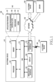
- FIG. 1 is a diagram illustrating a network environment including an electronic device according to various embodiments.
- the electronic device 101 includes a bus 110, a processor 120, a memory 130, an input/output interface 150, a display 160, and a communication interface 170.
- the bus 110 may include, for example, a circuit which interconnects the components 110 to 170 and delivers a communication (e.g., a control message and/or data) between the components 110 to 170.
- a communication e.g., a control message and/or data
- the processor 120 may include one or more of a Central Processing Unit (CPU), an Application Processor (AP), and a Communication Processor (CP).
- the processor 120 may carry out, for example, calculation or data processing relating to control and/or communication of at least one other component of the electronic device 101. An operation of processing (or controlling) the processor 120 according to various example embodiments will be described below in detail with reference to the accompanying drawings.
- the memory 130 may include a volatile memory and/or a non-volatile memory.
- the memory 130 may store, for example, commands or data relevant to at least one other component of the electronic device 101.
- the memory 130 may store software and/or a program 140.
- the program 140 may include, for example, a kernel 141, middleware 143, an Application Programming Interface (API) 145, and/or application programs (or "applications") 147.
- At least some of the kernel 141, the middleware 143, and the API 145 may be referred to as an Operating System (OS).
- OS Operating System
- the memory 130 may store one or more programs executed by the processor 120, and perform function for temporality storing data inputted and outputted by the processor 120. According to various embodiments of the present disclosure, the memory 130 may stores obtained data, data obtained in real time may stored in temporaily storing device and data determined to be stored may stored in long-time storable device.
- the memory 130 may include a computer readable recording medium having a program recorded thereon to execute the method according to various example embodiments in the processor 120.
- the kernel 141 may control or manage system resources (e.g., the bus 110, the processor 120, or the memory 130) used for performing an operation or function implemented in the other programs (e.g., the middleware 143, the API 145, or the application programs 147). Furthermore, the kernel 141 may provide an interface through which the middleware 143, the API 145, or the application programs 147 may access the individual components of the electronic device 101 to control or manage the system resources.
- system resources e.g., the bus 110, the processor 120, or the memory 130
- the kernel 141 may provide an interface through which the middleware 143, the API 145, or the application programs 147 may access the individual components of the electronic device 101 to control or manage the system resources.
- the middleware 143 may serve as an intermediary for allowing the API 145 or the application programs 147 to communicate with the kernel 141 to exchange data. Also, the middleware 143 may process one or more task requests received from the application programs 147 according to priorities thereof. For example, the middleware 143 may assign priorities for using the system resources (e.g., the bus 110, the processor 120, the memory 130, or the like) of the electronic device 101, to at least one of the application programs 147.
- the API 145 is an interface through which the applications 147 control functions provided from the kernel 141 or the middleware 143, and may include, for example, at least one interface or function (e.g., instruction) for file control, window control, image processing, character control, and the like.
- the input/output interface 150 may output the commands or data received from the other element(s) of the electronic device 101 to the user or another external device, or may transmit the command or data received from the user or the another external device to the other element(s) of the electronic device 101.
- wired/wireless headphone port, external charger port, wired/wireless data port, memory card port, audio input/output port, video input/output port, earphone port may be included in the input/output interface 150.
- Examples of the display 160 may include a Liquid Crystal Display (LCD), a Light-Emitting Diode (LED) display, an Organic Light-Emitting Diode (OLED) display, a MicroElectroMechanical Systems (MEMS) display, and an electronic paper display, or the like, but is not limited thereto.
- the display 160 may display, for example, various types of contents (e.g., text, images, videos, icons, or symbols) to users.
- the display 160 may include a touch screen, and may receive, for example, a touch, gesture, proximity, or hovering input using an electronic pen or a user's body part.
- the display 160 may displays the user visual output.
- the visual output may be indicated in a form of a text, a graphic, a video or any combination thereof.
- the display 160 may displays User Interface (UI) regarding usage of the electronic device or Graphical UI.
- UI User Interface
- the display 160 may display various UI or GUI associated with an operation performed by the electronic device 101.
- various examples of screens provided based on the UI is described according to figures illustrated as follows.
- the display 160 may includes a curved display (or a bended display) which is rolled, bended without damaged according to flexible substrates as thin as paper or flat display.
- the curbed display maintains bended shape and connected with a housing (e.g. bezel).
- the electronic device 101 may be implemented in a form like the curved display, and be implemented as a displaying apparatus which is rolled or unrolled by the user such as flexible display.
- the display 160 may get flexibility by substituting glass substrate with plastic film which covers the LCD of various displays described above.
- the communication interface 170 may establish communication, for example, between the electronic device 101 and an external device (e.g., a first external electronic device 102, a second external electronic device 104, or a server 106).
- an external device e.g., a first external electronic device 102, a second external electronic device 104, or a server 106.
- the communication interface 170 may be connected to a network 162 through wireless or wired communication, and may communicate with an external device (e.g., the second external electronic device 104 or the server 106).
- the wireless communication may use at least one of, for example, Long Term Evolution (LTE), LTE-Advance (LTE-A), Code Division Multiple Access (CDMA), Wideband CDMA (WCDMA), Universal Mobile Telecommunications System (UMTS), Wireless Broadband (WiBro), and Global System for Mobile Communications (GSM), as a cellular communication protocol.
- the wireless communication may include, for example, short range communication 164.
- the short-range communication 164 may include at least one of, for example, Wi-Fi, Bluetooth, Near Field Communication (NFC), and Global Navigation Satellite System (GNSS).
- GNSS may include, for example, at least one of global positioning system (GPS), global navigation satellite system (Glonass), Beidou Navigation satellite system (Beidou) or Galileo, and the European global satellite-based navigation system.
- GPS global positioning system
- Glonass global navigation satellite system
- Beidou Beidou Navigation satellite system
- Galileo European global satellite-based navigation system
- the wired communication may include, for example, at least one of a Universal Serial Bus (USB), a High Definition Multimedia Interface (HDMI), Recommended Standard 232 (RS-232), and a Plain Old Telephone Service (POTS).
- USB Universal Serial Bus
- HDMI High Definition Multimedia Interface
- RS-232 Recommended Standard 232
- POTS Plain Old Telephone Service
- the network 162 may include at least one of a telecommunication network such as a computer network (e.g., a LAN or a WAN), the Internet, and a telephone network.
- a telecommunication network such as a computer network (e.g., a LAN or a WAN), the Internet, and a telephone network.
- Each of the first and second external electronic devices 102 and 104 may be of a type identical to or different from that of the electronic device 101.
- the server 106 may include a group of one or more servers. According to various example embodiments of the present disclosure, all or some of the operations performed in the electronic device 101 may be executed in another electronic device or a plurality of electronic devices (e.g., the electronic devices 102 and104 or the server 106).
- the electronic device 101 may request another device (e.g., the electronic device 102 or 104 or the server 106) to execute at least some functions relating thereto instead of or in addition to autonomously performing the functions or services.
- Another electronic device e.g., the electronic device 102 or 104, or the server 106
- the electronic device 101 may process the received result as it is or additionally, and may provide the requested functions or services.
- cloud computing, distributed computing, or client-server computing technologies may be used.
- FIG. 2 is a block diagram illustrating an example electronic device according to various example embodiments of the present disclosure.
- the electronic device 201 may include, for example, all or a part of the electronic device 101 illustrated in FIG. 1 .
- the electronic device 201 includes one or more processors 210 (e.g., Application Processors (AP)), a communication module 220, a Subscriber Identification Module (SIM) 224, a memory 230, a sensor module 240, an input device 250, a display 260, an interface 270, an audio module 280, a camera module 291, a power management module 295, a battery 296, an indicator 297, and a motor 298.
- AP Application Processors
- SIM Subscriber Identification Module
- the aforementioned components of the electronic device 201 may disposed inside of a housing (or main body) of the electronic device 201 or may formed outside of the housing.
- the processor 210 may include various processing circuitry configured to control a plurality of hardware or software components connected to the processor 210 by driving an operating system or an application program, and perform processing of various pieces of data and calculations.
- the processor 210 may be embodied as, for example, a System on Chip (SoC).
- SoC System on Chip
- the processor 210 may further include a Graphic Processing Unit (GPU) and/or an image signal processor.
- the processor 210 may include at least some (for example, a cellular module 221) of the components illustrated in FIG. 2 .
- the processor 210 may load, into a volatile memory, commands or data received from at least one (e.g., a non-volatile memory) of the other components and may process the loaded commands or data, and may store various data in a non-volatile memory.
- the processor 210 may controls overall operation of the electronic device 201.
- the processor 210 may include one or more processors.
- the processor 210 may includes a communication processor, an application processor, an interface (e.g. GPIO, general purpose input/output), or internal memory as distinct components or incorporated in one or more integrated circuit.
- the AP performs various functions for the electronic device 201 by executing various software program
- the CP performs processing and controlling for audio communication and data communication.
- the processor 210 may enrolls for performing specific various functions corresponding to a software module (e.g. instruction set) by executing the specific software module stored in the memory 230.
- a software module e.g. instruction set
- the processor 210 may control operation of hardware module such as the audio module 280, the interface 270, the display 260, the camera module 291 or the like. According to various embodiments, the processor 210 may electrically connected to the display 260 and the memory 230 of the electronic device 201.
- the processor 210 processes touch operation by setting, removing or adjusting of touch block area (or touch non-processing area). According to various embodiments, the processor 210 may, when screen transition occurs by executing the application, transition of the application, page or scroll, transition the at least portion of the touch block area to touch area according to corresponding user interface, or including other area into the touch block area.
- the processor 210 may control detecting screen change, setting touch block area in an edge area in response to the screen change. According to various embodiments, the processor 210 may control determining exception area in the touch block area based on the UI, setting final touch block area by removing the determined exception area from the touch block area, processing touch event regarding the edge area based on the final touch area.
- the communication module 220 may have a configuration equal or similar to that of the communication interface 170 of FIG. 1 .
- the communication module 220 may include various communication circuitry, such as, for example, and without limitation, a cellular module 221, a Wi-Fi module 223, a BT module 225, a GNSS module 227, an NFC module 228, and a Radio Frequency (RF) module 229.
- the communication module 220 for example, further comprises WiGig module (not illustrated).
- WiFi module 223 and WiGig module may be imcorporatbly implemented in a form of a single chip.
- the cellular module 221 may provide a voice call, a video call, a text message service, or an Internet service through a communication network.
- the cellular module 221 may distinguish and authenticate the electronic device 201 in a communication network using the subscriber identification module 224 (for example, the SIM card).
- the cellular module 221 may perform at least some of the functions that the AP 210 may provide.
- the cellular module 221 may include a communication processor (CP).
- At least some (e.g., two or more) of the cellular module 221, the Wi-Fi module 223, the BT module 225, the GNSS module 227, and the NFC module 228 may be included in one Integrated Chip (IC) or IC package.
- IC Integrated Chip
- the RF module 229 may transmit/receive a communication signal (e.g., an RF signal).
- the RF module 229 may include, for example, a transceiver, a Power Amplifier Module (PAM), a frequency filter, a Low Noise Amplifier (LNA), and an antenna.
- PAM Power Amplifier Module
- LNA Low Noise Amplifier
- at least one of the cellular module 221, the WIFI module 223, the BT module 225, the GNSS module 227, and the NFC module 228 may transmit/receive an RF signal through a separate RF module.
- the WiFi module 223 may indicate a module for establishing a wireless Internet connection and a wireless LAN link with another external electronic device (e.g., another electronic device 102 or server 106).
- the WiFi module 223 may be externally or internally mounted on the electronic device 201.
- wireless Internet technology wireless fidelity (Wi-Fi), wireless broadband (Wibro), world Interoperability for microwave access (WiMax), high speed downlink packet access (HSDPA), millimeter wave (mmWave), or the like may be used.
- the WiFi module 223 may transmit or receive various data of the electronic device 201 to and from the outside, in conjunction with another external electronic device (e.g., another electronic device 104) connected to the electronic device 201 via a network (e.g., a wireless Internet network)(e.g., the network 162).
- a network e.g., a wireless Internet network
- the WiFi module 223 may always remain in a turned-on state or may be turned on/turned off according to the setting of the electronic device 201 or a user input.
- the Bluetooth module 225 and NFC module 228 may, for example, indicate a short-range communication module for performing short-range communication.
- a short-range communication technology Bluetooth, Bluetooth low energy (BLE), radio frequency identification (RFID), infrared data association (IrDA), ultra wideband (UWB), Zigbee, near field communication (NFC), or the like may be used.
- the short-range communication module may transmit or receive various data of the electronic device 201 to and from the external electronic device, in conjunction with another external electronic device (e.g., another electronic device 102) connected to the electronic device 201 via a network (e.g., a short-range communication network).
- the short-range communication module e.g. the Bluetooth module 225 and NFC module 228) may always remain in a turned-on state or may be turned on/turned off according to the setting of the electronic device 201 or a user input.
- the subscriber identification module 224 may include, for example, a card including a subscriber identity module and/or an embedded SIM, and may contain unique identification information (e.g., an Integrated Circuit Card Identifier (ICCID)) or subscriber information (e.g., an International Mobile Subscriber Identity (IMSI)).
- ICCID Integrated Circuit Card Identifier
- IMSI International Mobile Subscriber Identity
- the memory 230 may include, for example, an embedded memory 232 and/or an external memory 234.
- the embedded memory 232 may include at least one of a volatile memory (e.g., a Dynamic Random Access Memory (DRAM), a Static RAM (SRAM), a Synchronous Dynamic RAM (SDRAM), and the like) and a non-volatile memory (e.g., a One Time Programmable Read Only Memory (OTPROM), a Programmable ROM (PROM), an Erasable and Programmable ROM (EPROM), an Electrically Erasable and Programmable ROM (EEPROM), a mask ROM, a flash ROM, a flash memory (e.g., a NAND flash memory or a NOR flash memory), a hard disc drive, a Solid State Drive (SSD), and the like).
- a volatile memory e.g., a Dynamic Random Access Memory (DRAM), a Static RAM (SRAM), a Synchronous Dynamic RAM (SDRAM), and the like
- the memory 230 may store one or more programs, data or instructions associated with detecting a screen change, setting touch block area (or touch non-processing area) in an edge area in response to the screen change by processor. According to various embodiments, the memory 230 may store one or more programs, data or instructions associated with determining exception area in the touch block area based on the UI, setting final touch block area by removing the determined exception area from the touch block area, processing touch event regarding the edge area based on the final touch area.
- the memory 230 may includes extension memory (e.g. external memory 234) or embedded memory (e.g. internal memory 232).
- the electronic device 201 may operated associated with web storage performing storage function of the memory 230 in the internet.
- the memory 230 may stores one or more software (or software module).
- the software components may comprises an operating system software module, communication software module, graphic software module, user interface software module, MPEG (moving picture experts group) software module, camera software module or one or more of application software module.
- the module which is software components may expressed as set of instructions, therefore, the module may be expressed as an instruction set.
- the module may be expressed as a program.
- the memory 230 may further comprises additional module (instructions) with aforementioned modules, or as necessary, do not use some of the modules (the instructions).
- the operating system software module may comprise various software components to control general system operation.
- the controlling of the general system operation may refer to, for example, management and controlling memory, management and controlling storage hardware (device), or management and controlling power.
- the operating system software module may perform function to facilitate communication between various hardware (device) and software component (module).
- the communication software module may enable communication with other electronic devices, such as a wearable device, a smart phone, a computer, a server, or a portable terminal, via the communication module 220 or interface 270. Also, the communication software module may be configured with a protocol structure corresponding to the communication method.
- the graphics software module may include various software components for providing and displaying graphics on the display 260.
- the term graphic may be used to mean text, web page, icon, digital image, video, animation, and the like.
- the user interface software module may include various software components related to the user interface (UI). For example, it includes contents regarding how the state of the user interface is changed or under which conditions the change of the user interface state is made, and the like.
- An MPEG module may include software components that enable processes and functions (e.g, creation, playback, distribution, and transmission of content, and the like) related to digital content (e.g., video, audio).
- processes and functions e.g., creation, playback, distribution, and transmission of content, and the like
- digital content e.g., video, audio
- the camera software module may include camera-related software components that enable camera-related processes and functions.
- An application module may include a web browser including a rendering engine, a email, an instant message, a word processing, a keyboard emulation, an address book, touch list, widget, digital right management (DRM), iris scan, context cognition, voice recognition, positioning (position) determining function, location based service, and the like.
- the application module may include instructions for processing the touch event by changing the touch blocking area of the display 260 according to the user interface.
- the sensor module 240 may, for example, measure a physical quantity or sense the operating state of the electronic device 201 to convert the measured or sensed information into an electrical signal.
- the sensor module 240 may includes at least one of a gesture sensor 240A, a gyro sensor 240B, a barometer sensor 240C, a magnetic sensor 240D, an acceleration sensor 240E, a grip sensor 240F, a proximity sensor 240G, a color sensor 240H (e.g., RGB (red, green, blue), a medical sensor 240I, temperature-humidity sensor 240J, an illuminance sensor 240K, or a UV (ultra violet) sensor 240M.
- a gesture sensor 240A e.g., a gyro sensor 240B, a barometer sensor 240C, a magnetic sensor 240D, an acceleration sensor 240E, a grip sensor 240F, a proximity sensor 240G, a color sensor 240H (e.g
- the sensor module 240 may include, for example, an e-nose sensor, an electromyography (EMG) sensor, an electroencephalogram (EEG) sensor, an electrocardiogram sensor an electrocardiogram sensor, an infrared (IR) sensor, an iris scan sensor, and/or a finger scan sensor.
- the sensor module 240 may further include a control circuit for controlling at least one or more sensors included in the sensor module 240.
- the electronic device 201 further includes a processor configured to control the sensor module 240, either as part of the processor 210 or separately, to control the sensor module 240 while the processor 210 is in a sleep state.
- the input device 250 may include various input circuitry, such as, for example, and without limitation, a touch panel 252, a (digital) pen sensor 254, a key 256, or an ultrasonic input device 258.
- the touch panel 252 may use, for example, at least one of a capacitive type, a resistive type, an infrared type, and an ultrasonic type.
- the touch panel 252 may further include a control circuit.
- the touch panel 252 may further include a tactile layer, and provide a tactile reaction to the user.
- the (digital) pen sensor 254 may be part of, for example, a touch panel or may include a separate recognition sheet.
- the key 256 may include, for example, a physical button, an optical key, or a keypad.
- the ultrasonic input device 258 can sense the ultrasonic wave generated from the input tool through the microphone 288 and identify the data corresponding to the ultrasonic wave detected.
- the input device 250 may include an electronic pen.
- the input device 250 may be implemented to receive a force touch.
- the display 260 may include a panel 262, a hologram device 264, or a projector 266.
- the panel 262 may be implemented to be, for example, flexible, transparent, or wearable.
- the panel 262 may be embodied as one or more module with the touch panel 252.
- the panel 262 may include a pressure sensor (or force sensor) capable of measuring the intensity of the pressure on the user's touch.
- the pressure sensor may be integrated with the touch panel 252 or may be implemented by one or more sensors separate from the touch panel 252.
- the panel 262 may be seated in the display 260 and may sense user input contacting or approaching the surface of the display 260.
- the user input may comprise a touch input or proximity input based on at least one of a single-touch, a multi-touch, a hovering, or an air gesture.
- the panel 262 may receive user input to initiate operations associated with use of the electronic device 201 in various embodiments and may generate an input signal in accordance with the user input.
- the panel 262 may be configured to convert a change in capacitance, such as a pressure applied to a particular area of the display 260 or a specific area of the display 260, to an electrical input signal.
- the panel 262 can detect the location and area where an input tool (e.g., a user finger, an electronic pen, etc.) is touched or approximated on the surface of the display 260.
- an input tool e.g., a user finger, an electronic pen, etc.
- the panel 262 may be configured to detect pressure (e.g., force touch) at the time of touch according to the applied touch method.
- the hologram device 264 may show a three dimensional (3D) image in the air by using an interference of light.
- the projector 266 may project light onto a screen to display an image.
- the screen may be located, for example, in the interior of or on the exterior of the electronic device 201.
- the interface 270 may include various interface circuitry, such as, for example, and without limitation, a High-Definition Multimedia Interface (HDMI) 272, a Universal Serial Bus (USB) 274, an optical interface 276, or a D-subminiature (D-sub) 278.
- the interface 270 may be included in, for example, the communication interface 170 illustrated in FIG. 1 .
- the interface 270 may include, for example, a Mobile High-definition Link (MHL) interface, a Secure Digital (SD) card/Multi-Media Card (MMC) interface, or an Infrared Data Association (IrDA) standard interface.
- MHL Mobile High-definition Link
- SD Secure Digital
- MMC Multi-Media Card
- IrDA Infrared Data Association
- the interface 270 may receive data from another electronic device, or may receive power and communicate it to the respective configurations within the electronic device 201.
- the interface 270 may allow data within the electronic device 201 to be transmitted to other electronic devices.
- a wired / wireless headphone port, an external charger port, a wired / wireless data port, a memory card port, an audio input / output port, a video input / output port, an earphone port, and the like may be included in the interface 270.
- the audio module 280 may bilaterally convert a sound and an electrical signal. At least some components of the audio module 280 may be included in, for example, the input/output interface 150 illustrated in FIG. 1 .
- the audio module 280 may process voice information input or output through, for example, a speaker 282, a receiver 284, earphones 286, or the microphone 288.
- the audio module 280 may transmits the audio signal input from the processor 210 to an output device (e.g., a speaker 282, a receiver 284, or an earphone 286), and performs a function for transmitting an audio signal such as a voice received from an input device (e.g., the microphone 288) to the processor 210.
- the audio module 280 may output audio / sound data by converting the audio / sound data into audible sound under the control of the processor 210, and transmit the audio signal such as voice to the processor 210 by converting the audio signal into a digital signal.
- the speaker 282 or the receiver 284 may output audio data stored in the memory or received from the communication module 220.
- the speaker 282 or the receiver 284 may output an acoustic signal associated with various operations (functions) performed in the electronic device.
- the microphone 288 may receive an external acoustic signal and process it as electrical voice data.
- the microphone 288 may be implemented with various noise reduction algorithms for eliminating noise generated while receiving the external acoustic signal.
- the microphone 288 may be responsible for input of audio streaming such as voice commands or the like.
- the camera module 291 may include various circuitry including, for example, and without limitation, a camera, a device which may photograph a still image and a video, or the like. According to an embodiment of the present disclosure, the camera module 291 may include one or more image sensors (e.g., a front sensor or a back sensor), a lens, an Image Signal Processor (ISP) or a flash (e.g., LED or xenon lamp).
- image sensors e.g., a front sensor or a back sensor
- ISP Image Signal Processor
- flash e.g., LED or xenon lamp
- the camera module 291 may include a first camera (e.g., a color camera) to acquire color information and a second camera (e.g., an infrared (IR) camera) to acquire depth information (e.g., position information and distance information of a subject).
- a first camera e.g., a color camera
- IR infrared
- the first camera may capture a color image of the subject by converting a light inputted from the outside into am image signal.
- the camera module 291 may include an image sensor.
- the image sensor may be implemented as a CCD (charged coupled device) or a CMOS (complementary metal-oxide semiconductor).
- the first camera may be a front camera embedded on the front surface of the electronic device 201.
- the front camera may be replaced by the second camera, and may not be embedded at the front surface of the electronic device 201.
- the first camera may be placed together with the second camera on the front surface of the electronic device 201.
- the first camera may be a rear camera embedded on the rear surface of the electronic device 201.
- the first camera may be configured to include both the front camera and the rear camera, which are embedded on the front and back sides of the electronic device 201, respectively.
- the power management module 295 may manage, for example, power of the electronic device 201.
- the power management module 295 may include a Power Management Integrated Circuit (PMIC), a charger Integrated Circuit (IC), or a battery or fuel gauge.
- PMIC Power Management Integrated Circuit
- IC charger Integrated Circuit
- the PMIC may use a wired and/or wireless charging method.
- Examples of the wireless charging method may include, for example, a magnetic resonance method, a magnetic induction method, an electromagnetic wave method, and the like. Additional circuits (e.g., a coil loop, a resonance circuit, a rectifier, etc.) for wireless charging may be further included.
- the battery gauge may measure, for example, a residual quantity of the battery 296, and a voltage, a current, or a temperature while charging.
- the battery 296 may include, for example, a rechargeable battery and/or a solar battery.
- the indicator 297 may display a particular state (e.g., a booting state, a message state, a charging state, or the like) of the electronic device 201 or a part (e.g., the processor 210) of the electronic device 201.
- the motor 298 may convert an electrical signal into a mechanical vibration, and may generate a vibration, a haptic effect, or the like.
- the electronic device 201 may include a a mobile TV supporting device (e.g., a GPU) to process media data according to a certain standard such as Digital Multimedia Broadcasting (DMB), Digital Video Broadcasting (DVB), or mediaFLO TM .
- DMB Digital Multimedia Broadcasting
- DVD Digital Video Broadcasting
- mediaFLO TM mediaFLO
- Each of the above-described component elements of hardware according to the present disclosure may be configured with one or more components, and the names of the corresponding component elements may vary based on the type of electronic device. Some of the above-described elements may be omitted from the electronic device(e.g., the electronic device 101, 201), or the electronic device may further include additional elements. Also, some of the hardware components according to various embodiments may be combined into one entity, which may perform functions identical to those of the relevant components before the combination.
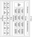
- FIG. 3 is a block diagram illustrating an example program module according to various example embodiments of the present disclosure.
- the program module 310 may include an Operating System (OS) for controlling resources related to the electronic device (e.g., the electronic device 101) and/or various applications (e.g., the application programs 147) executed in the operating system.
- OS Operating System
- the operating system may be, for example, AndroidTM, iOSTM, WindowsTM, SymbianTM, TizenTM, BadaTM, or the like.
- the program module 310 may include a kernel 320 (e.g., a kernel 141), middleware 330 (e.g., a middleware 143), an API 360 (e.g., an API 145), and/or applications 370 (e.g., an application program 147). At least some of the program module 310 may be preloaded on an electronic device, or may be downloaded from an external electronic device (e.g., the electronic device 102 or 104, or the server 106).
- a kernel 320 e.g., a kernel 141
- middleware 330 e.g., a middleware 143
- an API 360 e.g., an API 145
- applications 370 e.g., an application program 147
- the kernel 320 may include, for example, a system resource manager 321 and/or a device driver 323.
- the system resource manager 321 may control, allocate, or collect system resources.
- the system resource manager 321 may include a process management unit, a memory management unit, a file system management unit, and the like.
- the device driver 323 may include, for example, a display driver, a camera driver, a Bluetooth driver, a shared memory driver, a USB driver, a keypad driver, a Wi-Fi driver, an audio driver, or an Inter-Process Communication (IPC) driver.
- the middleware 330 may provide a function required in common by the applications 370, or may provide various functions to the applications 370 through the API 360 so as to enable the applications 370 to efficiently use the limited system resources in the electronic device.
- the middleware 330 may include at least one of a run time library 335, an application manager 341, a window manager 342, a multimedia manager 343, a resource manager 344, a power manager 345, a database manager 346, a package manager 347, a connectivity manager 348, a notification manager 349, a location manager 350, a graphic manager 351, and a security manager 352.
- the runtime library 335 may include a library module that a compiler uses in order to add a new function through a programming language while an application 370 is being executed.
- the runtime library 335 may perform input/output management, memory management, the functionality for an arithmetic function, or the like.
- the application manager 341 may manage, for example, a life cycle of at least one of the applications 370.
- the window manager 342 may manage Graphical User Interface (GUI) resources used by a screen.
- the multimedia manager 343 may recognize a format required for reproduction of various media files, and may perform encoding or decoding of a media file by using a codec suitable for the corresponding format.
- the resource manager 344 may manage resources of a source code, a memory, and a storage space of at least one of the applications 370.
- the power manager 345 may, for example, manage a battery or power source and may provide power information required for the operations of the electronic device. According to an embodiment, the power manager 345 may operate together with a Basic Input/Output System (BIOS).
- BIOS Basic Input/Output System
- the database manager 346 may generate, search for, and/or change a database to be used by at least one of the applications 370.
- the package manager 347 may manage installation or an update of an application distributed in
- the connectivity manager 348 may manage wireless connectivity.
- the notification manager 349 may display or notify of an event such as an arrival message, promise, proximity notification, and the like in such a way that does not disturb a user.
- the location manager 350 may manage location information of an electronic device.
- the graphic manager 351 may manage a graphic effect which will be provided to a user, or a user interface related to the graphic effect.
- the security manager 352 may provide all security functions required for system security, user authentication, or the like.
- the middleware 330 may further include a telephony manager for managing a voice call function or a video call function of the electronic device or may include a middleware module that forms a combination of various functions of the above-described components.
- the middleware 330 may provide a module specialized for each type of OS in order to provide a differentiated function.
- the middleware 330 may dynamically remove some of the existing components or add new components.
- the API 360 (e.g., the API 145) is, for example, a set of API programming functions, and may be provided with a different configuration according to an OS. For example, in the case of Android TM or iOS TM , one API set may be provided for each platform. In the case of Tizen TM , two or more API sets may be provided for each platform.
- the applications 370 may include, for example, one or more applications which may provide functions such as a home 371, a dialer 372, an SMS/MMS 373, an Instant Message (IM) 374, a browser 375, a camera 376, an alarm 377, a contact 378, a voice dial 379, an email 380, a calendar 381, a media player 382, an album 383, a watch 384, a health care (e.g., for measuring exercise quantity or blood sugar, etc.), or environment information (e.g., providing atmospheric pressure, humidity, or temperature information).
- IM Instant Message
- the applications 370 may include an information exchange application that supports information exchange between the electronic device and an external electronic device.
- the information exchange application may include, for example, a notification relay application for transferring specific information to an external electronic device or a device management application for managing an external electronic device.
- the notification relay application may transmits notification information generated by other application of the electronic device to an external electronic device, or providing a user notification information that is received from the external electronic device.
- the device management application may install, delete, or update at least one function of an external electronic device that communicates with the electronic device (for example, a function of turning on/off the external electronic device itself (or some components thereof) or a function of adjusting the brightness (or resolution) of a display), applications that operate in the external electronic device.
- the applications 370 may include applications (for example, a health care application of a mobile medical appliance, and the like) designated according to the attributes of an external electronic device.
- the applications 370 may include applications received from an external electronic device (for example, the server 106 or the electronic device 102 or 104).
- At least a part of the program module 310 may be implemented (e.g., executed) by software, firmware, hardware (e.g., the processor 210) or a combination of at least two or more of them, and may include a module for performing one or more functions, a program, a routine, sets of instructions or a process.
- module used herein may include a unit including hardware, software, or firmware, and, for example, may be interchangeably used with the terms “logic,” “logical block,” “component” or “circuit”.
- the “module” may be an integrally configured component or a minimum unit for performing one or more functions or a part thereof.
- the “module” may be implemented mechanically or electronically.
- the “module” may include an application-specific IC (ASIC) chip, a field-programmable gate array (FPGA), and a programmable-logic device for performing some operations, which are known or will be developed.
- ASIC application-specific IC
- FPGA field-programmable gate array
- At least part of a device for example, modules or functions thereof or a method (for example, operations) according to various embodiments may be implemented by instructions stored in a computer-readable storage media (for example, the memory 130,) in the form of a programmable module.
- a processor for example, the processor 120
- the processor may perform a function corresponding to the instruction.
- a computer-readable recording medium may include a hard disk, a floppy disk, a magnetic media (for example, a magnetic tape), an optical recording media (for example, compact disc read only memory (CD-ROM) and a digital versatile disc (DVD), a magneto-optical media (for example, a floptical disk)), an internal memory, or the like.
- an instruction may include a code generated by a compiler or a code executable by an interpreter.
- a module or a program module may include at least one of the above-described elements, or a portion of the above-described elements may be omitted, or additional other elements may be further included.
- Operations performed by a module, a program module, or other elements according to various embodiments may be executed sequentially, in parallel, repeatedly, or in a heuristic method. Also, at least part of operations may be executed in different sequences, omitted, or other operations may be added.
- a recording medium may include a computer readable recording medium which has a program recorded thereon to execute various methods described below in the processor 120, 210.
- an electronic device may include all devices that use one or more of various processors, such as an AP, a CP, a GPU, and a CPU.
- an electronic device may include an information communication device, a multimedia device, a wearable device, an IoT device, or various other devices corresponding to the aforementioned devices.
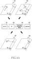
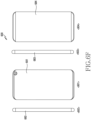
- FIG. 4A illustrates a method of processing a touch input generated in an electronic device according to various embodiments of the present disclosure.
- a display of the electronic device may include at least two or more regions.
- a display for example, example ⁇ 410>
- a flat surface display region for example, a region 411
- a curved display region for example, a region 412 formed on a right side surface of the flat surface display region is illustrated for convenience of explanation, and other elements of the electronic device except for the display will not be illustrated.
- the display of the electronic device may be functionally divided into two or more regions.
- the display region 411 and the display region 412 form a single display panel, but functions of the corresponding regions may be distinguished from each other.
- the display region 411 may be a region where a normal application (for example, a message application, a schedule management application, an Internet application, etc.) is executed
- the display region 412 may be a region where an icon of a frequently used application, etc. is displayed.
- the region of the display may be divided in various ways.
- the display may be divided into a main region and a sub region, a flat region and a curved region, a front surface region and a side surface region, a front surface region and a rear surface region, a region visible within a viewing angle and an invisible region, or a combination region of three or more of the above-mentioned regions.
- the display may be divided into a first region and a second region.
- a region where a normal application is executed or a user intentionally inputs a touch event is distinguished as a main display region (or a first region), and a region where a user' unintended touch event input occurs relatively easily is distinguished as a sub display region (or an edge region, a second region, etc.). Distinguishing as described above is merely for convenience of explanation, and does not limit embodiments of the present disclosure.
- display used in the present disclosure may be understood as a concept including a display supporting touch input functions of various types, such as an add-on type in which a touch screen panel (TSP) is coupled to an LCD panel, an on-cell type in which a touch screen panel is embedded in an LCD panel, and an in-cell type in which a touch function is embedded in an LCD panel.
- TSP touch screen panel
- a touch event inputted on the display may be processed by the processor 120, 210 including a processor circuit (for example, a processing circuitry) configured in the electronic device.
- the touch event may be inputted based on a change in capacitance of a touch panel included in the display, and may include a down event, an up event, a continuous event, or a multi-touch event.
- the down event may indicate an event that is inputted by a user pressing the touch panel with an input device including a finger, a touch pen (electronic pen), or the like.
- the up event may indicate an event which is inputted by the user releasing an input means from the touch panel after inputting the down event.
- the continuous event may indicate an event which is inputted by the user changing the position of the input device while holding the pressing state on the touch panel, after inputting the down event.
- the continuous event may be referred to as a drag in the technical field to which the present disclosure belongs.
- the multi-touch event may indicate the user inputting the down events at two or more points of the touch panel.
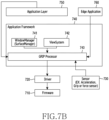
- a touch IC 401 may determine whether the touch event occurs, a type of the touch event, and an occurrence point.
- An application processor (AP) 403 may determine which region of the functionally divided regions of the display the occurrence point of the touch event corresponds to, and may provide at least one piece of information of information regarding whether the touch event occurs, the type of the touch event, the occurrence point, and the occurrence region to a touch input management module 405.
- the touch input management module 405 may determine a method of processing the touch event, based on at least one piece of information of the type of the touch event, the occurrence point, and the occurrence region. For example, regarding the touch event, the touch input management module 405 may determine whether to store the touch event, to process the touch event by itself by deleting, or to transmit the touch event to an application 407. According to an embodiment, when the touch event is the down event and is inputted to a specific region, it may be additionally determined whether the down event corresponds to a grip, and, when the down event corresponds to the grip, the touch input management module 405 may process and delete the touch event by itself. Examples of these operations will be described in detail with reference to the drawings described below.
- Example ⁇ 410> of FIG. 4A illustrates an example of a user's drag operation on the display region 411 through a touch event T1.
- an unintended touch event T2 may occur first by an input device such as a user's hand fixing the electronic device or an electronic pen.
- the touch IC 401 may detect the touch event T1 and the touch event T2, and may provide information regarding occurrence points to the AP 403.
- the AP 403 may determine which region of the display the touch event T1 and the touch event T2 are inputted to, respectively. For example, the AP 403 may determine that the touch event T1 is inputted through the region 411 and the touch event T2 is inputted through the region 412. The AP 403 may provide the touch event T2 inputted first to the touch input management module 405. For example, the AP 403 may provide information regarding the type of the touch event T2, the occurrence point, and the occurrent region to the touch input management module 405.
- the touch input management module 405 may also receive information indicating that the touch event T2 is detected on the region 412. In response to the information regarding the touch event T2 being received, the touch input management module 405 may determine whether the touch event T2 corresponds to a grip or an intended touch.
- the touch input management module 405 may determine whether a difference between a length of the longest portion (for example, a long axis) and a length of the shortest portion (for example, a short axis) of a shape of a touch region of the touch event T2 is less than or equal to a predetermined threshold value. When it is determined that the difference is less than or equal to the predetermined threshold value, the touch input management module 405 may determine that the shape of the touch region is close to a circular shape, and may estimate the touch event T2 as a touch input and may determine that the touch event is an intended touch.
- the touch input management module 405 may determine whether the difference between the length of the long axis and the length of the short axis of the shape of the touch region of the touch event T2 exceeds the predetermined threshold value. When it is determined that the difference exceeds the predetermined threshold value, the touch input management module 405 may determine that the shape of the touch region is close to an oval shape, and may estimate the touch event T2 as a grip input and may determine that the touch event corresponds to a grip. According to an embodiment, the touch input management module 405 may determine whether the touch event corresponds to a grip or a touch, based on a width (area) of the touch region or a touch input time. However, this should not be considered as limiting, and the touch input may be distinguished by various methods.
- the touch input management module 405 may process and delete the touch event T2 by itself. According to another embodiment, even when it is determined that the touch event T2 is a touch since a small area of the user's palm touches in a circular shape, the touch input management module 405 may not directly transmit the touch event T2 to the application 407 and may temporarily store the touch event T2 since the touch event T2 is inputted through the region 412.
- the AP 403 may transmit the touch event T1 to the touch input management module 405.
- the AP 403 may also provide information indicating that the touch event T2 occurs in the region 411.
- the touch input management module 405 may determine that the touch event T2 is already stored, and may delete the touch event T2 and may transmit only the touch event T1 to the application 407. As a result, a scroll caused by the touch event T2 is normally performed.
- Example ⁇ 420> of FIG. 4A illustrates an example in which the user performs a multi-touch function to zoom out an image through a touch event T1 and a touch event T2 on the region 421.
- a touch event T3 and a touch event T4 which are not intended may occur in the region 422 by an input device such as a user's hand griping the electronic device or an electronic pen.
- the touch input management module 405 may determine that the touch event T3 and the touch event T4 are a grip, and may delete the touch event T3 and the touch event T4.
- the touch input management module 405 may not directly transmit the touch event T3 and the touch event T4 to the application 407, and may store the same. Thereafter, when the touch event T1 and the touch event T2 detected from the region 421 are received, the touch input management module 405 may delete the touch event T3 and the touch event T4 which are already stored, and may transmit only the touch event T1 and the touch event T2 to the application 407. As a result, the touch event T1 and the touch event T2 which are intended by the user may be normally processed.
- Example ⁇ 430> of FIG. 4A illustrates an example in which a touch event T1 starting on the region 431 moves to the region 432.
- the touch input management module 405 may continuously transmit the touch event inputted to the region 431 to the application 407, and may not directly transmit the touch event inputted to the region 432 to the application 407 and may store the touch event. Thereafter, when the continuous event inputted to the region 432 is not moved by longer than a predetermined distance, the touch input management module 405 may delete the touch event on the region 432 stored.
- the touch input management module 405 may not directly transmit the touch event inputted to the region 432 to the application 407, and store the touch event, such that a function unintended by the user can be prevented from malfunctioning.
- Example ⁇ 440> of FIG. 4A illustrates an example in which a touch event T1 moves on the region 442 (for example, a scroll).
- the region 442 may be used as a region for adjusting brightness of the screen of the electronic device or a volume.
- the touch input management module 405 may store the touch event T1, and thereafter, when the touch event T1 is continuously inputted as a continuous event and a moving distance is greater than or equal to a threshold value, the touch input management module 405 may transmit the continuous touch event T1 to the application 407.
- the touch input management module 405 may estimate the touch event as a user's unintended touch event, and may delete the touch event T1. According to various embodiments, even when a touch-disabled region for preventing touch malfunction is not uniformly set in a portion close to the bezel of the electronic device, only a user's intended touch event can be filtered based on a moving distance of the touch event, etc., and accordingly, a malfunction problem of a function that is not intended by the user can be solved. Additional various embodiments to which the present disclosure is applicable will be described in detail with reference to the drawings presented below.
- the examples illustrated in FIG. 4A explain some of various types of input patterns that can be inputted to the electronic device, and are not intended to limit embodiments of the present disclosure.
- elements configuring the operations of the present disclosure implemented by hardware and/software as described in FIG. 4A may be expressed in various methods.
- the touch IC 401 for determining the occurrence of a touch event and an occurrence point may be expressed as a determination module for an input position.
- the AP 403 may be expressed as a processor, a control module or a processing module.
- the touch event may be generated not only by a direct touch input to the display region, but also by a proximity touch input.
- the application 407 may refer to an application which is being executed or an application to be executed by the touch event. In various embodiments, the application 407 may operate on an application layer.
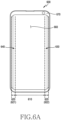
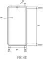
- FIG. 4B illustrates a method for processing a touch input generated in the electronic device according to various embodiments of the present disclosure.
- FIG. 4B is a view to illustrate a region of a display 450.
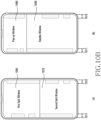
- the display 450 may be divided into a first region 451 (for example, a main display region) and a second region 452, 454 (for example, a sub display region).
- the display 450 may distinguish a region where a normal application is executed or a user intentionally inputs a touch event as the first region 451, and a region where a user's unintended touch event input occurs relatively easily as the second region 452, 454.
- the touch input management module 405 may process a touch event inputted to the second region 452, 454 in the same method as the method of processing the event inputted to the region 412, 422, 432, 442 as described above with reference to FIG. 4A .
- the touch input management module 405 may process a touch event inputted to the first region 451 in the same method as the method of processing the event inputted to the region 411, 421, 431, 441 as described above with reference to FIG. 4A .
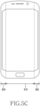
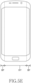
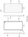
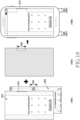
- FIG. 5A is a view illustrating a display form of an electronic device according to various embodiments of the present disclosure.
- the electronic device may be a multi-surface display device having a plurality of display surfaces on a front surface thereof.
- the display may include a first display disposed on a flat portion 510 of the front surface of the electronic device, a second display disposed on a left bending portion 520 of the front surface, and a third display disposed on a right bending portion 530.
- the first display to the third display may face first to third directions, respectively, and the first to third directions may be different from one another.
- a region displaying an image by means of the first display may be defined as a first display region
- a region displaying an image by means of the second display may be defined as a second display region
- a region displaying an image by means of the third display may be defined as a third display region.
- the first display to third display may be continuously connected with one another.
- the third display may be extended from the first display or the second display. Accordingly, at least a portion of the third display region may be extended from a periphery of the first display region or a periphery of the second display region.
- at least one of the second display and the third display disposed on the left bending portion 520 and the right bending portion 530 may include a curved display.
- FIGs. 5B , 5C , 5D , and 5E are views illustrating examples of screens configured in various methods in the electronic device including the plurality of displays according to various embodiments of the present disclosure.
- the first display to the third display as described above with reference to FIG. 5A may be independently driven and may display different images, or may display a single image in a continuous form, under control of a processor.
- the processor may execute an application and may provide a user interface through the display, and, in response to a user input, the processor may control a screen displayed based on at least a part of the first display to the third display.
- the processor controls a screen displayed on the first display to the third display according to various embodiments.
- the first display 511, the second display 521, and the third display 531 may display a single continuous screen on their respective display regions.
- the second display region of the second display 521 may display a screen connected with a left screen of the first display region of the first display 511
- the third display region of the third display 531 may display a screen connected with a right screen of the first display region of the first display 511.
- the first display 531 and the third display 533 may display a single continuous screen on their respective display regions, and the second display 523 may display another separate screen.
- the third display region of the third display 533 may display a screen connected with a right screen of the first display region of the first display 513, and the second display region of the second display 523 may display a screen separate from a left screen of the first display region of the first display 513.
- the first display 515 and the second display 525 may display a single continuous screen on their respective display regions, and a third display 535 may display another separate screen.
- the second display region of the second display 525 may display a screen connected with a left screen of the first display region of the first display 515
- the third display region of the third display 535 may display a screen separate from a right screen of the first display region of the first display 515.
- the first display 517, the second display 527, and the third display 537 may display separate screens on their respective display regions.
- the first display region of the first display 517 may display a specific screen (for example, a first screen)
- the second display region of the second display 527 may display a screen (for example, a second screen) separate from a left screen of the first display region of the first display 517
- the third display region of the third display 537 may display a screen (for example, a third screen) separate from a right screen of the first display region of the first display 517.
- the respective display regions (for example, the second display region, the third display region) of the second display 527 and the third display 537 may display different screens. According to various embodiments, at least one of the respective display regions (for example, the second display region, the third display region) of the second display 527 and the third display 537 may not display a screen and may operate in a turn-off state under control of the processor or according to a type of an application executed.
- FIGs. 6A and 6B are views to illustrate an example of an electronic device according to various embodiments of the present disclosure.
- FIGs. 6A and 6B illustrate an example of an electronic device 600 (for example, the electronic device 101 of FIG. 1 , the electronic device 201 of FIG. 2 ) having a curved display (or a bended display).
- the electronic device 600 is an electronic device having a curved display, although it is not limited thereto.
- the electronic device 600 includes an electronic device without a bezel region or having a very narrow configuration, and for example, may include an electronic device having a flexible display or a flat surface display.
- a display 660 (for example, the display 160 of FIG. 1 , the display 260 of FIG. 2 ) of the electronic device 600 may be extended to at least one side surface of the electronic device 600 (for example, at least one surface of a left side surface, a right side surface, an upper side surface, or a lower side surface), and may be bent by a radius of curvature (for example, 5 cm, 1 cm, 7.5 mm, 5 mm, 4 mm, or the like) at which the curved display is operable, or less, and may be coupled to the side surface of a housing 670 (or a bezel).
- a radius of curvature for example, 5 cm, 1 cm, 7.5 mm, 5 mm, 4 mm, or the like
- the display 660 may be implemented at a right angle without a radius of curvature.
- a region formed on a front surface of the curved display 660 may be referred to as a main display region 610 (for example, a first display region), and a region extended from the main display region 610, bent toward at least one side surface of the housing 670, and appearing on the side surface of the housing 670 may be referred to as a sub display region 620 (or an edge area) (for example, a left sub display region 621 (for example, a second sub display region), a right sub display region 622 (for example, a third sub display region), an upper sub display region 624 (for example, a fourth sub display region), which will be described below, a lower sub display region 623 (for example, a fifth sub display region), which will be described below).
- a sub display region 620 or an edge area
- a left sub display region 621 for example, a second sub display region
- a right sub display region 622 for example, a third sub display region
- an upper sub display region 624 for example, a fourth sub display
- the main display region 610 and the sub display region 620 are distinguished from each other for convenience of explanation, and do not mean as being physically divided from each other.
- the main display region 610 and the sub display region 620 may have at least one end formed in a bent shape, and the at least one bent end may be implemented by one curved display 660 extended to at least one side surface of the electronic device 600.
- the at least one bent end may be extended to the rear surface of the electronic device 600, and may be implemented according to an implementation method of the electronic device 600.
- the display 660 may support an input and an output, and may process an input and an output caused by the main display region 610 and the sub display region 620 simultaneously or individually.
- a right hand mode and a left hand mode of the electronic device 600 may be defined by using an environment configuration provided by the electronic device 600, a separate application, or a user's grip state.
- the electronic device 600 may process an input and an output only by using the sub display region 620 on a side surface corresponding to a corresponding mode. For example, when the electronic device 600 is set to the right hand mode in the example of FIG. 6A , the input and the output are achieved through the sub display region 620 on the right side surface 630 when viewed in front of the electronic device 600, and, when the electronic device 600 is set to the left hand mode, the input and the output are achieved through the sub display region 620 on the left side surface 640 when viewed in front of the electronic device 600.
- the sub display region 620 may include a dead zone 625.
- a part or entirety of the sub display region 620 will be referred to as an edge region 620 for convenience of explanation, and the edge region 620 will be described as being divided into an edge zone 627 where a touch input is processed according to a condition or processed insensitively, and a dead zone 625 where a touch is not effective.
- each of the edge regions 620 may be divided into the edge zone 627 which allows a conditional input or is an insensitive region, and the dead zone 625 where a touch is not effective, and may operate.
- the sub display region 620 of the electronic device 600 may be identified as a physical region (for example, the whole region of the sub display region 620) in terms of display, and may be identified as an independent region (for example, at least two independent regions) in terms of touch.
- the sub display region 620 when the sub display region 620 is divided in terms of touch, the sub display region 620 may divided into a first partial region of the sub display region 620 (for example, an inside partial region 627 in the sub display region 620 (hereinafter, an edge zone)), and a second partial region of the sub display region 620 (for example, an outside partial region 625 in the sub display region 620) (hereinafter, a dead zone)).
- the sub display region 620 may be a combination region of the dead zone 625 and the edge zone 627 in terms of touch.
- the region including the dead zone 625 and the edge zone 627 in terms of touch may be set to be the same as, larger (wider) than, or smaller (narrower) than the physical sub display region 620, according to settings of the electronic device 600.
- the edge zone 627 may be used as a term indicating a region including the whole region or inside region of the sub display region 620, for example, indicating the sub display region 620 itself, and the dead zone 625 may be used as a term indicating an outside region of the sub display region 620, that is, a region which is set not to process a touch by default.
- the dead zone 625 and the edge zone 627 may process only a specific touch input or may process a touch input according to a specific condition (for example, it is determined whether to process a first touch input according to a type of a second touch input, an input time difference, or the number of inputs).
- the specific condition when the specific condition is not satisfied, the corresponding touch input may be recognized as a grip or an unintended input and may be disregarded (for example, an input event drop).
- the electronic device 600 may control a touch input by distinguishing a region of the display 660 where a normal application is executed or the user intentionally inputs a touch event as the main display region 610 (for example, the first region), and distinguishing a region where a user's unintended touch event input occurs relatively easily as the sub display region 620 (for example, the second region).
- the electronic device 600 may distinguish between a touch input on the flat surface region and a touch input on the curved region, and may control the touch input.
- a touch event by the user is a touch event inputted to the sub display region 620.
- a touch event is inputted on a position which is set to a zone (for example, the dead zone 625) which does not receive an input of a touch itself with respect a part close to the bezel to prevent touch malfunction, or is inputted on a zone (for example, the edge zone 627) where an input of a touch itself is insensitively received or processed.
- the electronic device 600 when the user performs a touch input operation close to the bezel (for example, the sub display region 620, in particular, the dead zone 625), the electronic device 600 does not provide a function according to the touch input even if the touch input is a user's intended touch input.
- the electronic device 600 may not set the predetermined dead zone 625 (and/or the edge zone 627) as a zone which does not receive a touch input unconditionally, and may determine a component of a user interface on a position (and/or size) of the detected touch input, and may provide a function based on the touch event or may not provide the function.
- the dead zone 625 may indicate a region where a touch is not effective according to a user interface displayed through the display 660, that is, a region where a touch is not effective even when a touch event occurs (for example, a touch blocking region).
- the edge zone 627 (including the edge region 620) may be a region which is insensitive to a touch on the display 660 (for example, an insensitive region).
- the edge region 620 may be a region which operates in response to a specific input (for example, a tap, a scroll, etc.) under a specific condition.
- the electronic device 600 may include the flat surface region (for example, the main display region 610) and the curved surface region (for example, the sub display region 620) (for example, the left sub display region 621, the right sub display region 622).
- the display 660 of the electronic device 600 may include the dead zone 625 which is an input non-reception region for deleting (removing, unprocessing) a user's unintended touch event.
- a touch input parameter for processing a touch input in the electronic device 600 may include at least one parameter of a width of the dead zone 625, a width of the curved surface region (for example, the sub display region 620), a position and a size of a touch region when a user's touch event is inputted, or a difference between a length of a long axis and a length of a short axis in the touch region.
- the type of the touch input parameter is merely an example and is not limited thereto.
- At least some region or an entire region of the sub display region 620 may be set (or adjusted, changed) to a touch blocking region (a touch unprocessing region) or a touch region (a touch-enabled region) in terms of touch.
- the touch blocking region may be set to be turned on/off based on at least part or entirety of the edge zone 627 set to allow a touch to be effective under a specific condition, and the dead zone 625 set to allow a touch to be ineffective, which are divided in the sub display region 620.
- the touch blocking region may indicate a region in the sub display region 620 that is set to disregard a touch event in order to prevent a touch error caused by a user's unintended touch input.
- the touch blocking region may include a region where a touch is not effective (for example, the dead zone 625).
- the touch blocking region may include a region in the touch insensitive region (for example, the edge zone 627) that is set according to a user interface.
- the touch blocking region may be set to disregard a corresponding input according to a user interface, even in response to a specific input (for example, a tap, a scroll, etc.) set in the edge zone 627.
- the touch blocking region is set in the entire region (for example, the dead zone 625, the edge zone 627) of the sub display region 620, and the touch blocking region is adjusted based on a user interface, for convenience of explanation.
- the electronic device may set the touch blocking region to a tough region where a touch input is enabled by controlling (or adaptively removing or adjusting) the touch blocking region.
- the electronic device may change the touch blocking region to the touch input-enabled region by removing or adjusting the dead zone 625.
- the electronic device may change the touch blocking region to the touch input-enabled region by removing or adjusting the edge zone 627 and the dead zone 625.
- the electronic device may change the touch blocking region to the touch input-enabled region by removing or adjusting the edge zone 627.
- the electronic device 600 can exactly filter a user's intended touch event by adjusting the touch blocking region made by the dead zone 625 and the edge zone 627 according to a user interface.
- adjusting the touch blocking region may include changing the touch blocking region to the touch region by removing at least part of the edge zone 627 and/or the dead zone 625 from the touch blocking region, or extending a setting range of the touch blocking region by including a least some region of the other region (for example, the main display region 610) than the touch blocking region in the touch blocking region.
- the dead zone 625 and the edge zone 627 may be adaptively changed according to a user interface displayed on the display 660. For example, as shown in FIG. 6B , based on whether at least some component of a user interface drawn on the display 660 (for example, various objects (for example, an icon, an image, a text, a link, or etc.) included in the user interface, for example, objects 631, 632, 633) is positioned on (or overlap) the sub display region 620 (for example, a region including the dead zone 625 and the edge zone 627, and hereinafter, referred to as the edge region 620 for convenience of explanation), or whether the component (for example, objects 631, 632, 633) is touchable on a corresponding position of the edge region 620, a setting value of the touch blocking region regarding at least part of the edge zone 627 and the dead zone 625 with respect to the corresponding region of the edge region 620 may be changed.
- various objects for example, an icon, an image, a text,
- the user may frequently cause an unintended touch input on the edge region 620 due to the structure of the electronic device when gripping the electronic device 600 with one hand.
- a related-art method disregards an inputted touch event based on a touch area or a touch time on the edge region 620 (for example, the dead zone 625, the edge zone 627) in order to solve a touch error problem.
- this may cause a problem that a user's intended touch input on the edge region 620 cannot be processed (for example, the touch is not effective).
- Various embodiments disclose a method and an apparatus which can exactly filter a user's intended touch event, and transmit the touch event to an application layer, thereby preventing malfunction.
- the touch event by the user may be processed by additionally setting more regions to the touch blocking region in addition to the edge region 620, or by removing a part of the edge region 620 set as the touch blocking region from the touch blocking region, according to a user interface of an application.
- the electronic device 600 may set the touch blocking region in each edge region 621, 622 differently according to a shape of a user interface provided on the left edge region 621 and the right edge region 622. According to an embodiment, the electronic device 600 may set at least some region of the touch blocking region in the edge region 620 as an exception region, according to a user interface specified to the edge region 620.
- FIGs. 6C , 6D , and 6E are views illustrating another example of the electronic device according to various embodiments of the present disclosure.
- FIGs. 6C , 6D , and 6E illustrate an example of an electronic device 600 of a different form (for example, the electronic device 101 of FIG. 1 , the electronic device 201 of FIG. 2 ) having a curved display (or a flexible display).
- the electronic device 600 illustrated in FIGs. 6C , 6D , and 6E may have a narrower bezel region that that of the electronic device 600 illustrated in FIGs. 6A and 6B , and the front surface of the electronic device 600 may be implemented by the display 660.
- the electronic device 600 illustrated in FIGs. 6C , 6D , and 6E may be an electronic device implemented in the form of a front facing display.
- the electronic device 600 may have a camera 650 (for example, a front facing camera) positioned on the region of the display 660.
- a camera 650 for example, a front facing camera
- example ⁇ A> of FIG. 6C illustrates that the camera 650 is positioned on the center of the upper end of the electronic device 600
- example ⁇ B> of FIG. 6C illustrates that the camera 650 is positioned on a side surface of the upper end (for example, a right upper end) of the electronic device 600.
- the electronic device 600 may include the main display region 610 and the sub display region 620 (or the edge region) (for example, the left sub display region 621, the right sub display region 622, the upper sub display region 624, the lower sub display region 623) which is extended from the main display region 610, is bent toward at least one side surface (for example, the left side surface, the right side surface, the upper side surface, or the lower side surface) of the housing (or bezel) 670, and appears on the side surface of the housing 670, as described above with reference to FIGs. 6A and 6B .
- the main display region 610 and the sub display region 620 are distinguished from each other for convenience of explanation, and do not mean as being physically divided.
- FIG. 6C illustrates an example in which the display 660 of the electronic device 600 is extended to the left side surface and the right side surface of the electronic device 600, and is coupled to the side surfaces (for example, both side surfaces) of the housing 670 (or bezel).
- the sub display region 620 (for example, the left sub display region 621, the right sub display region 622) is configured on both side surfaces from the main display region 610.
- FIG. 6D illustrates an example in which the display 660 of the electronic device 600 is extended to the left side surface, right side surface, upper side surface or lower side surface of the electronic device 600, and is coupled to at least part of the side surface (for example, upper, lower, left, or right side surface) of the housing 670 (or bezel).
- the sub display region 620 for example, the left side sub display region 621, the right sub display region 622) (for example, the first sub display region) may be configured on the left and right side surfaces from the main display region 610
- the sub display region 620 for example, the upper sub display region 624, the lower sub display region 623) (for example, the second sub display region) may be configured on the upper and lower side surfaces.
- the display 660 of the electronic device 600 may be extended to at least one side surface (for example, at least one surface of the left, right, upper, or lower side surface), and may configure one or more sub display regions 620 (for example, 621, 622, 623, 624) according to an implementation form of the display 660.
- the touch blocking region may be adjusted based on the four surfaces of the electronic device 600 (for example, the sub display region 620 on the left side surface, right side surface, upper side surface, or lower side surface).
- the electronic device 600 may distinguish between the first sub display region 620 (for example, 621, 622) and the second sub display region 620 (for example, 623, 624) according to an operation mode (for example, a landscape mode or a portrait mode) of the electronic device 600, and may operate.
- the electronic device 600 of FIGs. 6D and 6E may be an electronic device having an upper, lower, left, or right flexible display, or an electronic device which form displays (for example, the sub display region 620) on all of the upper, lower, left, and right side surfaces, and does not have a bezel or has a narrower bezel.
- the touch blocking region when the electronic device 600 operates in the portrait mode, the touch blocking region may be adjusted based on the first sub display region 620 (for example, 621, 622), and, when the electronic device 600 operates in the landscape mode, the touch blocking region may be adjusted based on the second sub display region 620 (for example, 623, 624).
- the shape of user's hand gripping the electronic device 600 may vary according to an operation mode of the electronic device 600, and the sub display regions 620 and the touch blocking region corresponding thereto may be implemented according to the operation mode of the electronic device 600.
- FIGs. 6F , 6G , and 6H are views to illustrate still another example of the electronic device according to various embodiments of the present disclosure.
- FIGs. 6F , 6G , and 6H illustrate an example of an electronic device 600 of a different form (for example, the electronic device 101 of FIG. 1 , the electronic device 201 of FIG. 2 ) having a curved display (or a flexible display).
- the electronic device 600 illustrated in FIGs. 6F , 6G , and 6H may be an example of an electronic device which has a display extended to a rear side surface of the electronic device 600 and has at least three surfaces (for example, a front side surface, a left side surface, a right side surface, a rear side surface, an upper side surface, or a lower side surface) implemented as a display.
- 6F , 6G , and 6H may be an electronic device (for example, a 4D sided wrap around display) having at least four surfaces (for example, a front side surface, a left side surface, a right side surface, a rear side surface, an upper side surface, or a lower side surface) surrounded by a display.
- a 4D sided wrap around display having at least four surfaces (for example, a front side surface, a left side surface, a right side surface, a rear side surface, an upper side surface, or a lower side surface) surrounded by a display.
- the electronic device 600 may include a first display region 681 of a first surface 601 (for example, a front side), a second display region 682 of a second surface 602 (for example, a left side), a third display region 683 of a third surface 603 (for example, a right side), and a fourth display region 684 of a fourth surface 604 (for example, a rear side).
- the first display region 681, the second display region 682, the third display region 683, and the fourth display region 684 are distinguished from one another for convenience of explanation, and do not mean as being physically divided. This should not be considered as limiting, and the electronic device 600 according to various embodiments may have the first display region 681, the second display region 682, the third display region 683, and the fourth display region 684 implemented as independent displays, for example, as physically divided displays.
- the electronic device 600 may distinguish between the display regions according to an operation mode of the electronic device 600 (for example, a front mode ( FIG. 6G ), or a rear mode ( FIG. 6H )).
- an operation mode of the electronic device 600 for example, a front mode ( FIG. 6G ), or a rear mode ( FIG. 6H )
- the electronic device 600 may use the first display region 681 of the first surface 601 (for example, the front side) as a main display region, and may use at least one of the second display region 682 of the second surface 602 (for example, the left side), the third display region 683 of the third surface 603 (for example, the right side), and the fourth display region 684 of the fourth surface 604 (for example, the rear side) as a sub display region.
- the electronic device 600 may set at least part (for example, both side surfaces) of the first display region 681, and all of the second display region 682, the third display region 683, and the fourth display region 684 as touch blocking regions.
- the electronic device 600 may set a part of an edge region of the first display region 681 as a dead zone 690 as described above, and may set all of the second display region 682, the third display region 683, and the fourth display region 684 as dead zones 690. According to various embodiments, the electronic device 600 may change the touch blocking region of the main display region according to a user interface drawn based on the main display region (for example, the first display region 681).
- the electronic device 600 may use the fourth display region 684 of the fourth surface 604 (for example, the rear side) as a main display region, and may use at least one of the second display region 682 of the second surface 602 (for example, the left side), the third display region 683 of the third surface 603 (for example, the right side), and the first display region 681 of the first surface 601 (for example, the front side) as a sub display region.
- the electronic device 600 may set at least part (for example, both side surfaces) of the fourth display region 684, and all of the second display region 682, the third display region 683, and the first display region 681 as touch blocking regions.
- the electronic device 600 may set a part of an edge region of the fourth display region 684 as a dead zone 690 as described above, and may set all of the second display region 682, the third display region 683, and the first display region 684 as dead zones 690. According to various embodiments, the electronic device 600 may change the touch blocking region of the main display region according to a user interface drawn based on the main display region (for example, the fourth display region 684).
- a position of the electronic device 600 gripped by the user and the shape of user's hand gripping may vary according to an operation mode of the electronic device 600.
- a touch blocking region may be set differently according to an operation mode of the electronic device 600, and the touch blocking region may be changed based on a user interface on the main display region.
- FIG. 7A is a view illustrating an inner structure of an electronic device which processes a touch input according to various embodiments of the present disclosure.
- the electronic device may include a display 701 supporting a touch function, and hardware 709 for processing a touch input.
- the electronic device may include various layers on a kernel 707 (for example, the kernel 141) to process the touch input.
- a kernel 707 for example, the kernel 141
- an OS input framework 705, an application 703A, 703B, or the like may be included in the electronic device.
- the display 701 may be divided into a main display region 701A and a sub display region 701B.
- the display 701 may be divided into a first region which is a region where a normal application is executed or a user intentionally inputs a touch event, and a second region which is a region where a user's unintended touch event input occurs relatively easily. Dividing as described above is merely an example, and the display 701 may include the first region and the second region which are functionally distinguished from each other.
- the display 701 may have the first region which has a flat surface, and the second region which is functionally distinguished from (may be physically connected with) the first region, and has a curved surface extended from the first region.
- the first region may correspond to the main display region 701A
- the second region may correspond to the sub display region 701B.
- a touch IC 709B may recognize a touch event occurring on the display 701, and may determine a point (coordinates) where the touch event occurs.
- the touch IC 709B may determine the occurrence point of the corresponding touch event based on a change in capacitance of a touch panel.
- the touch IC 709B may be understood as a kind of determination module, and the determination module may determine an occurrence point of an event occurring on a touch panel using a resistive or optical method (for example, an infrared ray method, an ultrasonic method) in addition to a capacitive method.
- the touch IC 709B may receive an input (for example, a gesture, short-range communication, long-range communication data, a speech signal) for determining display coordinates through the module illustrated in FIG. 2 , and may determine the occurrence point of the event.
- an input for example, a gesture, short-range communication, long-range communication data, a speech signal
- the touch IC 709B may transmit the touch event (for example, a touch signal) to the kernel 707 in a method such as interrupt through an application processor (AP) 709A.
- the AP 709A may be understood as a kind of processing module.
- the AP 709A may control and process various operations performed in the electronic device.
- the AP 709A when the AP 709A is provided in the form of a system on chip (SoC), the AP 709A may perform graphic processing (for example, a GPU function) and/or communication function (for example, a function of a communication processor (CP)), in addition to an arithmetic operation.
- graphic processing for example, a GPU function
- communication function for example, a function of a communication processor (CP)
- the AP 709A may determine whether the occurrence point of the touch event corresponds to the main display region 701A or the sub display region 701B, based on the point (coordinates) where the touch event occurs.
- the AP 709A may include information according to the result of determining, and may provide the touch event to a touch input management module included in the OS input framework 705.
- the touch event received through an I 2 C driver 707A may be transmitted to the OS input framework 705 (for example, an Android input framework) through a TSP driver 707B.
- the TSP driver 707B or the touch input management module included in the OS input framework 705 may determine a method for processing the touch event received from the AP 709A as described above with reference to FIG. 4A . Thereafter, the TSP driver 707B or the touch input management module included in the OS input framework 705 may determine whether to store the touch event, to process by deleting by itself, or to transmit the touch event to the application 703A, 703B, according to the determined processing method.
- the application 703A may be executed on the main display region 701A, and the application 703B may be executed on the sub display region 701B.
- the application 703A and the application 703B may be different applications, and one application may support a different form or function and the applications may be performed on respective regions.
- a video replay application a video screen (for example, corresponding to the application 703A) may be replayed on the main display region 701A, and a control menu (for example, a list, previous, next, pause, play, mute, or the like) (for example, corresponding to the application 703B) for controlling play/volume may be outputted to the sub display region 701B.
- a touch event in response to a touch event inputted to the main display region 701A and/or the sub display region 701B, it may be determined whether the touch event is a user's intended touch event or not by filtering, and a result of determining may be transmitted to the application 703A and/or the application 703B, such that touch malfunction caused by user's unintended touch event can be prevented.
- FIGs. 7B and 7C are views to illustrate an operation of processing a touch input in an electronic device according to various embodiments of the present disclosure.
- FIG. 7B is a view to illustrate an example of a framework or a platform of the electronic device, for performing operations according to various embodiments.
- the framework of the electronic device may include an entirety or a part of the program module 310 of the electronic device illustrated in FIG. 3 .
- the electronic device may include firmware 710, a driver 720, a sensor 730, an application framework 740, an application layer 750, and an edge application 760.
- the firmware 710 may include a basic program for controlling hardware.
- the firmware 710 may perform at least part of functions executed by software or hardware in the electronic device.
- the driver 720 may be included in a kernel (for example, the kernel 141).
- the driver 720 may include a device driver which provides a network interface and various hardware interfaces, in addition to a core system service supporting multitasking and processing memory management and process execution and management.
- the driver 720 may include various drivers such as a display driver, a camera driver, a keypad driver, a USB driver, a Bluetooth driver, a binder (IPC) driver, audio drivers, or the like.
- the sensor 730 may include, for example, an entirety or a part of the sensor module 240 illustrated in FIG. 2 . According to an embodiment, the sensor 730 may include an acceleration sensor, a pressure sensor, or a grip sensor.
- the application framework 740 may indicate a set of services forming an environment where an application of the electronic device is executed and managed. According to an embodiment, the concept that applications of the electronic device are configured by components which can be reused, can mutually operate and can be replaced may be implemented in the application framework 740.
- the application framework 740 may include, for example, an entirety or a part of the middleware 330 illustrated in FIG. 3 . According to various embodiments, the application framework 740 may include a window manager 741 (for example, the window manager 342 of FIG. 3 ), a view system 742, and a grip processor 743.
- the window manager 741 may manage a window seen on the screen of the electronic device.
- the window manager 741 may be, for example, an abstraction module regarding a surface manager of a library (not shown).
- the window manager 741 may divide the window seen on the screen, and may change setting of a touch blocking region of the edge region 620 according to a value set in the window.
- the window manager 741 may process a region in the touch blocking region that corresponds to the window into an exception region where a touch is effective.
- the view system 742 may indicate a set of extendable views which are used to generate a user interface of an application.
- the view system 742 may provide components of a user interface, such as a button, a list, or the like, and may manage event dispatching, layout, drawing, or the like.
- the view system 742 may calculate a position and a size of a view, and may change setting of the touch blocking region when the view overlaps the touch blocking region of the edge region 620.
- the view system 742 may process at least some region of the touch blocking region that corresponds to a view into an exception region where a touch is effective.
- the grip processor 743 may determine a grip state (for example, a grip intensity, etc.) of the electronic device, and may store a grip region where the grip occurs.
- the grip processor 743 may set a periphery region of a predetermined range around the grip region as a touch blocking region.
- the grip processor 743 may store information (for example, a touch event) transmitted from at least one of the window manager 741, the edge application 760, or the sensor 730.
- the grip processor 743 may set the periphery region of the predetermined range around the grip region as the touch blocking region, based on priorities of the respective pieces of information transmitted from the window manager 741, the edge application 760, or the sensor 730.
- the application layer 750 may use the subordinate kernel or system library through the application framework 740.
- the application layer 750 may include, for example, an entirety or a part of the application 370 illustrated in FIG. 3 .
- the application layer 750 may include the edge application 760.
- the edge application 760 may process a function of a user interface specified for the edge region 620.
- FIG. 7C is a view illustrating an example of a block of the application layer 750 of FIG. 7B .
- FIG. 7C illustrates examples of components of the respective applications of the application layer 750.
- the applications may be provided through a plurality of windows 751, 752, 753.
- the windows 751, 752, 753 may overlap one another according to the Z-order.
- Each of the windows 751, 752, 753 may include one or more views 771, 772, 773.
- an electronic device may include: a display (for example, the display 160, 260) configured to display a user interface; a memory (for example, the memory 230); and a processor (for example, the processor 120, 210) functionally connected with the display and the memory.
- the processor may be configured to: set a touch blocking region in an edge region of the display; determine an exception region in the touch blocking region, based on the user interface; set a final touch blocking region by removing the determined exception region from the touch blocking region; and process a touch event on the edge region, based on the final touch blocking region.
- the touch blocking region is a region that operates in the edge region and does not process a touch event.
- the processor may be configured to: identify a setting value for a touch blocking region set by an application in response to a screen change; when the setting value exists, set the touch blocking region based on the setting information; and, when the setting value does not exist, set the touch blocking region based on a default setting value.
- the processor may be configured to determine the exception region in the set touch blocking region, based on at least part of a position or a size of a component of the user interface or whether the component is touchable; and,
- the processor may be configured to remove a region set in an edge application for the edge region from the touch blocking region.
- the processor may be configured to, when the component receives a touch input and overlaps the touch blocking region of the edge region, process a region in the touch blocking region that corresponds to the component into the exception region.
- the processor may be configured to implement a touch blocking region differently according to each edge region, according to a form of a user interface provided to a plurality of edge regions.
- the processor may be configured to: obtain sensor information based on a sensor; and, when the sensor information exceeds a threshold value, increase a range of the touch blocking region.
- the processor may be configured to, when the electronic device detects a touch event in a grip state of the electronic device, operate a predetermined periphery region with reference to a grip region as a touch blocking region.
- the processor may be configured to; determine whether the touch event is included in the periphery region; and, when the touch event is included in the periphery region, drop the touch event by the touch blocking region.
- FIG. 8 is a flowchart illustrating an operation method of an electronic device according to claimed embodiments of the present disclosure.
- FIG. 8 illustrates an example to illustrate an operation of setting or extending a touch blocking region in a touch region or a touch-disabled region of a display, when processing a touch input in an electronic device according to various embodiments.
- a processor for example, the processor 120, 210 of FIG. 1 or 2 , hereinafter, referred to as the processor 210) of the electronic device executes an application.
- the processor 210 executes a specific application based on a user input, and displays a relevant execution screen through the display (for example, the display 160, 260 of FIG. 1 or 2 , hereinafter, referred to as the display 260).
- the processor 210 determines information of a touch blocking region based on the application. For example, the processor 210 may determine whether the corresponding application is an application using an edge region based on the type of the application, or may determine setting information of a touch blocking region in an edge region predetermined by the application.
- the processor 210 sets a touch blocking region where a touch event is disregarded, based on the touch blocking region information determined in operation 803.
- the processor 210 identifies a user interface of the application. According to an embodiment, the processor 210 may identify a component of the user interface configuring the screen currently displayed through the display 260. According to various embodiments, the processor 210 may determine a component positioned on the edge region from among various components of the user interface, and may determine whether a touch is enabled by the corresponding component.
- the processor 210 sets at least part of the touch blocking region as an exception region, based on the user interface. For example, with respect to the touch blocking region set as default based on the application, the processor 210 may reset a touch blocking region based on the user interface. According to an embodiment, the processor 210 may remove at least some region of the edge region from the touch blocking region in response to the user interface. According to various embodiments, the processor 210 may set the at least some region as the exception region of the touch blocking region. According to an embodiment, the processor 210 may set a region in the touch region where a component requiring a touch is positioned, as the exception region, for example, may remove the region from the touch blocking region.
- the processor 210 may set at least some region of the other region (for example, a main display region) except for the touch blocking region, as an additional region of the touch blocking region, based on the user interface. According to an embodiment, the processor 210 may additionally set a position of a region or a component which does not require a touch as the touch blocking region.
- the processor 210 may detect a screen change.
- the processor 210 may detect a change (for example, a surface change) of the screen currently displayed.
- the screen change may include a change of the currently displayed screen due to, for example, execution of an application, a change of an application, a page change, or a scroll.
- the screen change may include a change of the position of the component of the user interface.
- the processor 210 may reset the touch blocking region and the exception region in response to the screen change being changed. For example, the processor 210 may perform the operation of setting an exception region in the touch blocking region based on a user interface displayed according to the screen change, as described above with reference to operation 809.
- FIG. 9 is a flowchart illustrating an operation method of an electronic device according to various embodiments of the present disclosure.
- FIG. 9 may illustrate an example of an operation of processing a touch input in an electronic device according to various embodiments.
- the processor 210 of the electronic device may detect a screen change.
- the processor 210 may detect a change (for example, a surface change) of the screen displayed on the display 260.
- the screen change may include a change of the currently displayed screen due to, for example, execution of an application, a change of an application, a page change, or a scroll.
- the screen change may include a change of a position of a component position of a user interface.
- the processor 210 may identify information set in the application. For example, the processor 210 may determine setting information of a touch blocking region set with respect to an edge region by the application. According to an embodiment, the application may have setting information regarding whether at least part (for example, an upper, lower, left, or right part) of the edge region is used, or whether the used edge region is set as a touch blocking region. For example, when being executed, the application may display the edge region and may set whether a touch can be inputted through the edge region, based on the setting information.
- the application may display the edge region and may set whether a touch can be inputted through the edge region, based on the setting information.
- the processor 210 may determine whether setting information by the application exists or not. For example, the processor 210 may determine whether setting information exists in the corresponding application, based on the result of identifying the information in operation 903.
- the processor 210 may automatically set a touch blocking region in operation 907.
- the processor 210 may set the touch blocking region according to default information.
- the processor 210 may set the edge region (for example, an upper, lower, left, or right region) as the touch blocking region.
- the processor 210 may set the touch blocking region according to an operation mode (for example, a landscape mode, a portrait mode, a front mode, a rear mode, etc.) of the electronic device.
- the processor 210 may set the touch blocking region, and may proceed to operation 911 to perform operations after operation 911.
- the processor 210 may set a touch blocking region based on the setting information of the application in operation 909. For example, the processor 210 may set an entire region or some region of the edge region as the touch blocking region, based on the setting information of the application. The processor 210 may set the touch blocking region, and may proceed to operation 911 to perform operations after operation 911.
- the processor 210 may determine a position of a component and determine whether a touch is enabled by the component. For example, the processor 210 may identify a user interface of the application. According to an embodiment, the processor 210 may identify a component of a user interface configuring the screen currently displayed through the display 260. The processor 210 may determine a component positioned on the edge region from among the various components of the user interface, and determine whether a touch is enabled by the corresponding component.
- the processor 210 may remove at least some region of the touch blocking region in the edge region from the touch blocking region, based on the component of the edge region. For example, the processor 210 may set at least part of the touch blocking region as an exception region, based on the user interface. For example, the processor 210 may reset a touch blocking region (for example, a second touch blocking region) based on the user interface, with respect to the touch blocking region (for example, a first touch blocking region) set by the application or automatically set. According to an embodiment, the processor 210 may set a region in the edge region where a component requiring a touch is positioned, as an exception region, for example, may remove the corresponding region from the touch blocking region.
- a touch blocking region for example, a second touch blocking region
- the processor 210 may set a region in the edge region where a component requiring a touch is positioned, as an exception region, for example, may remove the corresponding region from the touch blocking region.
- the processor 210 may set at least some region of the other region (for example, a main display region) except for the touch blocking region, as an additional region of the touch blocking region, based on the user interface. According to an embodiment, the processor 210 may additionally set a position of a region or a component that does not require a touch, as the touch blocking region.
- the processor 210 may remove a region that is set by an edge application in the edge region from the touch blocking region.
- the edge application may operate independently from the currently executed application, and may receive a touch input based on the edge region. Accordingly, the processor 210 may remove some region in the edge region set as the touch blocking region from the touch blocking region according to setting of the edge application, and may set the corresponding region as an exception region.
- the processor 210 may process a touch input. For example, the processor 210 may disregard a touch event on the touch blocking region, and may process a touch event on the other region except for the touch blocking region.
- FIGs. 10A , 10B , 11 , and 12 are views illustrating an example of setting a touch blocking region in an electronic device according to various embodiments of the present disclosure.
- FIGs. 10A , 10B , and 11 illustrate an example of splitting a touch blocking region which makes a touch ineffective or is insensitive, according to a user interface of an application
- FIG. 12 illustrate an example of splitting a touch blocking region according to an edge user interface for an edge region.
- the electronic device may set various touch blocking regions based on at least one surface of the upper, lower, left, and right side surfaces by using an API in an application, when changing the screen.
- the touch blocking region may be set based on default setting.
- the application may split the edge region and may apply at least some regions of the edge region as a touch blocking region, based on a set value corresponding to a user interface.
- the application may split the edge region (for example, a first edge region 1001, a second edge region 1002) into at least one surface such as an upper, lower, left, or right side surface, and may differently set a size of a touch blocking region on each surface.
- the application may set the first edge region 1001 and the second edge region 1002 as touch blocking regions of different sizes (for example, a width).
- the application may divide the first edge region 1001 and the second edge region 1002 into an upper end and a lower end with reference to a specific boundary 1050 (for example, a virtual boundary), and may set the edge regions on the upper end and the lower end as touch blocking regions of different sizes.
- the specific boundary 1050 may be defined as a point for dividing (or splitting) the display region according to a user interface.
- the electronic device may set the touch blocking regions based on the first edge region 1001 (for example, a left edge region) and the second edge region 1002 (for example, a right edge region) by default.
- the electronic device may split the touch blocking regions based on the first edge region 1001 and the second edge region 1002 according to a set value of the application, and may set the touch blocking regions to have different values.
- the electronic device may set, as an exception region, a region where an object (for example, a component) is positioned in the touch blocking region on the left upper end of the first edge region 1001, and may set the other region 1010 except for the exception region as the touch blocking region (for example, a dead zone).
- the electronic device may set, as the touch blocking region (for example, a dead zone), the entire region 1020 where an object (for example, a component) is not positioned in the touch blocking region on the left lower end of the first edge region 1001.
- the electronic device may set a region where an object (for example, a component) is positioned in the touch blocking region on the right upper end of the second edge region 1002, as an exception region, and may set the other region 1030 except for the exception region as the touch blocking region (for example, a dead zone).
- the electronic device may set some region of the touch blocking region on the right lower end of the second edge region 1002 as an exception region (for example, a touch region, an edge zone (insensitive region)), and may set some of the other regions 1040 as the touch blocking region (for example, a dead zone).
- an exception region for example, a touch region, an edge zone (insensitive region)
- the other regions 1040 for example, a dead zone
- the electronic device may operate at least two applications, simultaneously, based on split windows (or multi windows).
- the electronic device may provide a pop-up window (or a mini window) on the full window in the form of pop-up.
- the electronic device may provide a first application (for example, a contact application, etc.) through a first split window 1060, and may provide a second application (for example, a web browser application, etc.) through a second split window 1070.
- touch blocking regions may be set based on a first edge region 1011 (for example, a left edge region) and a second edge region 1012 (for example, a right edge region).
- the electronic device may set the touch blocking regions by the first edge region 1011 and the second edge region 1012 in the first split window 1060 to have different values according to a set value of the first application.
- the electronic device may set the touch blocking regions by the first edge region 1011 and the second edge region 1012 in the second split window 1070 to have different values according to a set value of the second application. According to various embodiments, the electronic device may set the touch blocking regions by the first edge region 1011 and the second edge region 1012 in the first split window 1060 and the second split window 1070 to have different values according to respective user interfaces corresponding to the first application and the second application, as shown in the example of FIG. 10B described above.
- the electronic device may provide a third application (for example, a standby screen, a home screen, an application screen, etc.) through the full window 1090, and may provide a fourth application (for example, a call application, etc.) on a certain region of the full window 1090 through a pop-up window 1080 in the form of pop-up.
- a third application for example, a standby screen, a home screen, an application screen, etc.
- a fourth application for example, a call application, etc.
- the touch blocking regions by the first edge region 1011 and the second edge region 1012 may be set to have different values independently or by interworking with each other. According to an embodiment, as described above with reference to FIGs.
- the electronic device may set the touch blocking regions by the first edge region 1011 and the second edge region 1012 in the respective windows to have different values, according to set values of the respective applications (for example, the third application, the fourth application) of the pop-up window 1080 and the full window 1090.
- the electronic device may set the touch blocking regions by the first edge region 1011 and the second edge region 1012 in the pop-up window 1080 and the full window 1090 to have different values, according to respective user interfaces corresponding to the third application and the fourth application.
- the electronic device may set a part of a touch blocking region as an exception region, based on a component configuring a user interface, or may further extend the touch blocking region.
- the electronic device may recognize a component (for example, a view, a window, etc.) (for example, a region where an object 1110 is positioned) positioned on an edge region, and may set a touch blocking region (for example, a dead zone) according to the component positioned on the edge region or may set the region in the touch blocking region where the component is positioned as an exception region (for example, a touch region, an insensitive region). For example, the electronic device may remove the region where the component is positioned from the touch blocking region, and may change the corresponding region to a touch-enabled region.
- a component for example, a view, a window, etc.
- a touch blocking region for example, a dead zone
- the electronic device may remove the region where the component is positioned from the touch blocking region, and may change the corresponding region to a touch-enabled region.
- the electronic device may set the position of the component as the touch blocking region or as the exception region, according to whether the component is touchable on the corresponding position.
- the electronic device may determine the position of the component, such as a view, a window, etc., configuring the application, and may determine whether the component is touchable, and may change settings of the touch blocking region variously.
- it may be determined whether a touch is enabled by the component, based on whether there is an address linked by the component, or whether the component corresponds to a simply displayed object.
- Various embodiments are possible.
- FIG. 12 illustrates an example of setting a touch blocking region based on an edge user interface for an edge region 1230.
- the electronic device may process at least part 1260 of a touch blocking region (for example, a dead zone), separately set in an application, not to operate as the touch blocking region through the API.
- the electronic device may set a part (for example, a region where an edge handler 1200 is positioned) of the touch blocking region as the exception region (for example, a touch region, an insensitive region) by an edge application.
- the edge application may be operated by the edge handler 1200, and to achieve this, a touch should be effective on the edge handler 1200.
- the edge application may set the touch blocking region, except for the region 1260 corresponding to the size of the edge handler 1200 in a second edge region 1232 assigned the edge handler 1200 from among edge regions 1230 (for example, a first edge region 1231, the second edge region 1232).
- the electronic device may process the region 1260 where the edge handler 1200 is positioned not to operate as the touch blocking region.
- FIG. 13 is a flowchart illustrating an operation of setting a touch blocking region in an electronic device according to various embodiments.
- FIG. 13 may illustrate an example of an operation of adding an exception region to a touch blocking region based on a component (for example, a window) of an application according to various embodiments.
- the processor 210 of the electronic device may collect a window to receive an input.
- the processor 210 may determine a window enabling a touch input in a displayed user interface.
- the processor 210 may determine a window capable of receiving a touch input from among one or more windows configurating a user interface of an application.
- the processor 210 may determine whether the collected window corresponds to a full window (for example, a full screen window).
- the processor 210 may maintain setting of a touch blocking region in operation 1309. For example, the processor 210 may not set an exception region in the touch blocking region.
- the processor 210 may determine whether the collected window overlaps a touch blocking region in operation 1305. For example, the processor 210 may determine whether the collected window is positioned on the touch blocking region of the edge region that is set to make a touch ineffective.
- the processor 210 may maintain setting of the touch blocking region in operation 1309. For example, the processor 210 may not set an exception region in the touch blocking region.
- the processor 210 may process at least some region of the touch blocking region that corresponds to the collected window into an exception region. For example, the processor 210 may change a touch blocking region that corresponds to a position (and a size) of the collected window, in the touch blocking region of the edge region set to make a touch ineffective, to a touch-enabled region (for example, a touch region, an insensitive region). An example of this operation is illustrated in FIG. 14 .
- the touch blocking region of a corresponding region where the window is positioned may be processed not to operate, for example, may be processed to operate as a touch region. This may be automatically processed in a framework of the electronic device.
- operations 1301, 1303, and 1305 are not limited to the above-described sequence (or order), and operations 1301, 1303, and 1305 may be performed serially or in parallel, or may be performed in a different order. For example, operations may be performed in various orders, such as an order of operations 1301, 1305, and 1303.
- FIG. 14 is a view to illustrate an operation of setting a touch blocking region in an electronic device according to various embodiments of the present disclosure.
- the electronic device may collect an independent window 1400 rather than a full window (for example, a window configuring a home screen).
- the independent window 1400 may include a window of a different layer (for example, a window configurating a function or application icon) which is independent from the full screen window (for example, the window configuring the home screen) in FIG. 14 .
- the electronic device may determine whether a touch is enabled by the independent window 1400. For example, the electronic device may determine whether it is possible to receive a touch input through the independent window 1400. The electronic device may determine whether the collected independent window 1400 overlaps a touch blocking region set in an edge region 1430 (for example, a first edge region 1431, a second edge region 1432).
- an edge region 1430 for example, a first edge region 1431, a second edge region 1432.
- the electronic device may maintain setting of the touch blocking region when the collected window 1400 is the full screen window, is not able to receive a touch input, or does not overlap the touch blocking region.
- the electronic device may exclude the corresponding region (for example, a region corresponding to a position and a size of the window 1400 or a larger region) from the touch blocking region.
- the electronic device may process the corresponding region where the collected window 1400 is positioned into an exception region not to operate as the touch blocking region.
- FIG. 15 is a flowchart illustrating an operation of processing a touch blocking region as an exception region in an electronic device according to various embodiments of the present disclosure.
- FIG. 15 may illustrate an example of an operation of adding an exception region with respect to a touch blocking region, based on a component (for example, a view) of an application according to various embodiments.
- the processor 210 of the electronic device may calculate a size of a view.
- the processor 210 may calculate respective sizes of one or more views configuring a user interface of an application.
- the processor 210 may determine whether the size of the view is a full screen view or a view of a predetermined size (or a predetermined region).
- the processor 210 may maintain setting of the touch blocking region. For example, the processor 210 may not set an exception region in the touch blocking region.
- the processor 210 may calculate a position of the view. For example, the processor 210 may determine the position of a view of a predetermined size rather than the full screen view.
- the processor 210 may determine whether the position of the view overlaps the touch blocking region. For example, the processor 210 may determine whether the view is positioned on the touch blocking region which is set to make a touch ineffective in the edge region.
- the processor 210 may maintain the setting of the touch blocking region in operation 1511. For example, the processor 210 may not set an exception region in the touch blocking region.
- the processor 210 may determine whether the view is a view processing a touch input in operation 1507. For example, the processor 210 may determine whether the corresponding view is a touch input-enabled view, for example, a view capable of receiving a touch input. In various embodiments, operation 1507 may not be performed. For example, the view is normally able to process a touch input. Accordingly, when it is assumed that the view is a view for a touch input, operation 1507 may be omitted.
- the processor 210 may maintain the setting of the touch blocking region in operation 1511. For example, the processor 210 may not set an exception region in the touch blocking region.
- the processor 210 may process a region in the touch blocking region that corresponds to the view into an exception region. For example, the processor 210 may change a touch blocking region corresponding to the position and the size of the view, in the touch blocking region set to make a touch ineffective in the edge region, to a touch-enabled region (for example, a touch region). An example of this operation is illustrated in FIG. 16 .
- the electronic device may process the touch blocking region of the corresponding region where the view is positioned not to operate, for example, to operate as a touch region. This may be automatically processed in a framework of the electronic device.
- operations 1501, 1503, 1505, and 1507 are not limited to the above-described sequence (or order), and operations 1501, 1503, 1505, and 1507 may be performed serially or in parallel, or may be performed in a different order.
- a view for processing a touch input may be determined from among views positioned on the touch blocking region, and an exception region may be processed.
- FIG. 16 is a view to illustrate an operation of setting a touch blocking region in an electronic device according to various embodiments of the present disclosure.
- the electronic device may extract a view 1600 configuring an application.
- the electronic device may extract a touch-enabled view from among views configuring the application.
- the electronic device may calculate a size (for example, a length 1650) and a position of the view 1600.
- the electronic device may determine whether the view 1600 overlaps a touch blocking region set in an edge region 1630 (for example, a first edge region 1631, a second edge region 1632), based on a result of calculating.
- the view 1600 overlaps the touch blocking region of the second edge region 1632.
- the electronic device may maintain setting of the touch blocking region.
- the electronic device may exclude the corresponding region (for example, a region corresponding to the position and the size of the view 1600, or a larger region) from the touch blocking region.
- the electronic device may process the corresponding region where the view 1600 is positioned into an exception region not to operate as the touch blocking region.
- the touch blocking region when the touch blocking region is set by the application as described above with reference to FIGs. 13 , 14 , 15 , and 16 , at least some region (for example, a region corresponding to a position and a size of a window able to receive a touch input) of the touch blocking region may be processed into an exception region, based on the window of the application.
- at least some region when the touch blocking region is not set by the application, at least some region (for example, a region corresponding to a position and a size of a view able to receive a touch input) of the touch blocking region may be processed into an exception region, based on a view system of the application.
- the electronic device may automatically process the touch blocking region (for example, a dead zone) corresponding to the component in the touch blocking region not to operate through a framework.
- FIG. 17 is a flowchart illustrating an operation method of setting a touch blocking region in an electronic device according to various embodiments of the present disclosure.
- the processor 210 of the electronic device may detect a screen change.
- the processor 210 may detect a change (for example, a surface change) of the screen displayed on the display 260.
- the screen change may include a change of a currently displayed screen due to, for example, execution of an application, a change of an application (for example, a hierarchical change), a page change or a scroll.
- the screen change may include a change of a position of an object of a user interface.
- the processor 210 may determine whether there is a value set in relation to an edge region in an application in response to the screen change being detected. For example, the processor 210 may determine whether there is a value set to allow at least one edge region of upper, lower, left, or right edges to operate as a touch blocking region. According to an embodiment, the processor 210 may determine whether there is a touch blocking region set in a window on the uppermost end of the Z-order.
- the processor 210 may set a touch blocking region through a view system in operation 1705. According to an embodiment, the processor 210 may remove at least some region corresponding to the position and the size of the view in the touch blocking region from the touch blocking region as described above. For example, the processor 210 may set the touch blocking region where the view is positioned as an exception region not to operate as the touch blocking region.
- the processor 210 may proceed to operation 1707, and may set a touch blocking region (for example, apply an exception region) through the window in operation 1707.
- the processor 210 may set a touch blocking region through the window in operation 1707. According to an embodiment, the processor 210 may remove at least some region corresponding to the position and the size of the window in the touch blocking region from the touch blocking region as described above. For example, the processor 210 may set the touch blocking region where the window is positioned as an exception region not to operate as the touch blocking region.
- the processor 210 may set a final touch blocking region based on results of processing in operation 1705 or 1707. For example, the processor 210 may set the final touch blocking region based on the remaining region obtained by removing the exception region from the value or the default value set for the touch blocking region.
- FIG. 18 is a view to illustrate an operation of setting a touch blocking region in an electronic device according to various embodiments of the present disclosure.
- FIG. 18 illustrates an example of structurally processing a touch blocking region based on each item of an application and an edge user interface.
- the electronic device may provide a plurality of windows 1815, 1825 while overlapping the same in a hierarchical structure according to the Z-order.
- a first window 1815 may be a window on an uppermost end, and a second window 1825 may exit under the first window 1815 according to the Z-order.
- the first window 1815 and the second window 1825 may overlap each other in part or entirely, or may not overlap each other.
- the first window 1815 and the second window 1825 may not overlap each other.
- the Z-order of the independent mini windows may be determined according execution or setting.
- an exception region may be set in a touch blocking region according to each application according to the Z-order. For example, in the case of the first window 1815, an exception region may be set based on an edge handler 1810 of the touch blocking region. In the case of the second window 1825, an exception region may be set based on a view (or window) 1820 of the touch blocking region. According to various embodiments, an exception region may be processed from the touch blocking region based on at least one of the window or the view of the application as described above with reference to FIG. 17 .
- the electronic device may process an exception region in a touch blocking region by the API.
- the electronic device may apply some region 1830 (for example, an edge handler region) of the touch blocking region as an exception region, based on the API.
- some region 1830 for example, an edge handler region
- the electronic device may process the touch blocking region not to operate in some region 1830 through the API.
- a final touch blocking region obtained by removing the exception region (for example, the region corresponding to the edge handler 1810 in the second edge region 1852) from the touch blocking region of the edge region 1850 (for example, the first edge region 1851, the second edge region 1852) may be provided.
- the electronic device may provide the region of the edge handler 1810 in the touch blocking region of the edge region 1850 not to operate as the touch blocking region, that is, provide as a touch-enabled touch region.
- FIG. 19 is a flowchart illustrating an operation method of using sensing information of an electronic device according to various embodiments of the present disclosure.
- the processor 210 of the electronic device may detect an event by a sensor.
- the processor 210 may detect occurrence of an acceleration sensor event based on an acceleration sensor.
- the processor 210 may detect occurrence of a pressure sensor event based on a pressure sensor.
- the processor 210 may obtain sensor information. According to an embodiment, the processor 210 may obtain sensor information (for example, tilt information) sensed from the acceleration sensor. According to an embodiment, the processor 210 may obtain sensor information (for example, pressure information) sensed from the pressure sensor. According to an embodiment, the processor 210 may obtain first sensor information sensed from the acceleration sensor and second sensor information sensed from the pressure sensor.
- sensor information for example, tilt information
- sensor information for example, pressure information
- the processor 210 may obtain first sensor information sensed from the acceleration sensor and second sensor information sensed from the pressure sensor.
- the processor 210 may compare the sensor information and a predetermined threshold value. According to an embodiment, the processor 210 may determine whether the tilt information exceeds a specific threshold value. According to an embodiment, the processor 210 may determine whether the pressure information exceeds a specific threshold value.
- the processor 210 may maintain setting of a touch blocking region in operation 1907.
- the processor 210 may increase (or extend) the touch blocking region. An example of these operations is illustrated in FIG. 20 .
- FIG. 20 is a view illustrating an example of setting a touch blocking region based on sensor information in an electronic device according to various embodiments of the present disclosure.
- FIG. 20 may illustrate an example of a state in which a touch blocking region of an edge region 2030 (for example, a first edge region 2031, a second edge region 2032) set in the electronic device as default increases by a predetermined size 2010 (for example, a first predetermined size 2011, a second predetermined size 2012).
- a predetermined size 2010 for increasing may vary (for example, may be further extended or reduced) based on the sensor information.
- the predetermined size 2010 for increasing may increase only a certain surface (for example, the first edge region 2031 or the second edge region 2032) of the edge region 2030, or may increase all surfaces (for example, the first edge region 2031 and the second edge region 2032), according to a grip state (for example, a grip area, gripping by the left hand, gripping by the right hand, etc.) of the electronic device.
- the electronic device may increase the touch blocking region on the first edge region 2031 by the first predetermined size 2011, and may increase the touch blocking region on the second edge region 2032 by the second predetermined size 2012.
- the first predetermined size 2011 and the second predetermined size 2012 may be set to the same size or different sizes.
- a user's situation may be recognized based on various sensors (for example, the acceleration sensor or the pressure sensor), and the touch blocking region may be changed according to the user situation.
- a tilt in response to the acceleration sensor event by the acceleration sensor, a tilt may be calculated based on a tilt calculation method as shown in Equations 1 and 2 presented below.
- Equation 1 may indicate a vector sum along three acceleration axes
- Equation 2 may indicate a tilt angle through calculation with the Z-axis.
- the electronic device may determine that the user is lying, and may increase (extend) the touch blocking region.
- the electronic device may determine a grip state based on the acceleration sensor, and, when it is determined that the user is lying based on the grip state, the electronic device may increase the touch blocking region.
- the electronic device may include the pressure sensor in the edge region, and may determine an intensity of a user's grip based on the pressure sensor.
- the touch blocking region may be increased (extended). For example, when the intensity of the grip is high, there is a high possibility that malfunction is caused by a touch stretched to the display (or screen).
- the electronic device may determine the intensity of the grip based on the pressure sensor, and, when the intensity of the grip exceeds a specific threshold value, the electronic device may increase the touch blocking region.
- FIG. 21 is a view illustrating an operation method of using sensor information in an electronic device according to various embodiments of the present disclosure.
- the processor 210 of the electronic device may detect a state in which the user grips the electronic device.
- the grip state may be detected by analyzing a touched area based on various sensors (for example, the grip sensor, the pressure sensor, etc.).
- the processor 210 may store a grip region in response to the grip state being detected.
- the processor 210 may store a position (for example, a coordinate region) where the grip occurs (for example, a touched region).
- the processor 210 may also set a periphery region of a predetermined range with reference to an outer edge of the grip region.
- the grip region may correspond to a touch blocking region, and the periphery region may be an increased region of the touch blocking region.
- examples of the grip region and the periphery region are illustrated in FIG. 22 .
- the processor 210 may detect a touch event. For example, the processor 210 may detect another additional touch event after detecting the grip state.
- the processor 210 may determine whether a touch region according to the touch event is included in the periphery region of the grip region in response to the touch event being detected. For example, the processor 210 may determine whether the touch region according to the touch event is included in the periphery region or is outside the periphery region.
- the processor 210 may process the touch event in operation 2109. For example, the processor 210 may control a relevant function in response to the touch event.
- the processor 210 may drop the touch event in operation 2111. For example, when the touch region according to the touch event is included in the periphery region, the processor 260 may determine that an additional input occurs due to a change of the corresponding grip state. Accordingly, the processor 260 may determine the additional input as a touch event by the touch blocking region, and may not process the corresponding touch event.
- FIG. 22 is a view illustrating an example of setting a touch blocking region based on a grip region in an electronic device according to various embodiments of the present disclosure.
- FIG. 22 is a view to illustrate an example of dropping a touch on the periphery region of the grip area when the grip occurs.
- a predetermined periphery region 2230 may be set to operate as a touch blocking region with reference to a grip region 2210. For example, when a touch sensor is in an edge region (or a side surface of the electronic device) of the electronic device, a touch may always occur when the electronic device is gripped. In addition, a touch noise may occur on the periphery of the grip region 2210 where the grip occurs, due to an operation of gripping the electronic device on the palm.
- the grip when the grip is recognized and then an additional touch event occurs, it may be determined whether coordinates according to the touch event are included in the periphery region 2230 set based on the grip region 2210 recognized as a grip. In various embodiments, when the coordinates according to the touch event are included in the periphery region 2230, the corresponding touch events may be all blocked. For example, the periphery region 2230 may be set to operate as the touch blocking region.
- an operation method of an electronic device may include: setting a touch blocking region in an edge region of a display; determining an exception region in the touch blocking region, based on a user interface; setting a final touch blocking region by removing the determined exception region from the touch blocking region; and processing a touch event on the edge region, based on the final touch blocking region.
- the touch blocking region may be a region that operates in the edge region and may not process a touch event.
- determining the exception region may include: in response to a screen change, identifying a setting value for a touch blocking region by an application; when the setting value exists, setting the touch blocking region based on the setting information; and when the setting value does not exist, setting the touch blocking region based on a default setting value.
- determining the exception region may include determining the exception region in the set touch blocking region, based on at least part of a position or a size of a component of the user interface or whether the component is touchable, and
- setting the final touch blocking region may include removing a region set in an edge application for an edge region from the touch blocking region.
- setting the final touch blocking region may include, when the component receives a touch input and overlaps the touch blocking region of the edge region, processing a region in the touch blocking region that corresponds to the component into the exception region.
- a touch blocking region may be differently implemented according to each edge region, according to a form of a user interface provided to a plurality of edge regions.
- the operation method may further include: obtaining sensor information based on a sensor; and, when the sensor information exceeds a threshold value, increasing a range of the touch blocking region.
- the electronic device when the electronic device detects a touch event while being gripped, the electronic device may operate a predetermined periphery region with reference to the grip region as a touch blocking region.
- operating as the touch blocking region may include determining whether the touch event is included in the periphery region; and, when the touch event is included in the periphery region, dropping the touch event by the touch blocking region.
Landscapes
- Engineering & Computer Science (AREA)
- General Engineering & Computer Science (AREA)
- Theoretical Computer Science (AREA)
- Human Computer Interaction (AREA)
- Physics & Mathematics (AREA)
- General Physics & Mathematics (AREA)
- User Interface Of Digital Computer (AREA)
Applications Claiming Priority (2)
| Application Number | Priority Date | Filing Date | Title |
|---|---|---|---|
| KR1020160098226A KR102545602B1 (ko) | 2016-08-01 | 2016-08-01 | 전자 장치 및 그의 동작 방법 |
| PCT/KR2017/006696 WO2018026102A1 (ko) | 2016-08-01 | 2017-06-26 | 전자 장치 및 그의 동작 방법 |
Publications (3)
| Publication Number | Publication Date |
|---|---|
| EP3483714A1 EP3483714A1 (en) | 2019-05-15 |
| EP3483714A4 EP3483714A4 (en) | 2019-08-21 |
| EP3483714B1 true EP3483714B1 (en) | 2024-01-17 |
Family
ID=61072937
Family Applications (1)
| Application Number | Title | Priority Date | Filing Date |
|---|---|---|---|
| EP17837154.8A Active EP3483714B1 (en) | 2016-08-01 | 2017-06-26 | Electronic device and operation method therefor |
Country Status (4)
| Country | Link |
|---|---|
| US (1) | US11016603B2 (ko) |
| EP (1) | EP3483714B1 (ko) |
| KR (1) | KR102545602B1 (ko) |
| WO (1) | WO2018026102A1 (ko) |
Families Citing this family (17)
| Publication number | Priority date | Publication date | Assignee | Title |
|---|---|---|---|---|
| KR20190054397A (ko) * | 2017-11-13 | 2019-05-22 | 삼성전자주식회사 | 디스플레이장치 및 그 제어방법 |
| KR102550042B1 (ko) | 2018-05-25 | 2023-06-30 | 삼성전자주식회사 | 디스플레이를 통해 어플리케이션의 콘텐트를 표시하는 방법 및 이를 구현한 전자 장치 |
| KR102569170B1 (ko) | 2018-08-09 | 2023-08-22 | 삼성전자 주식회사 | 사용자 입력이 유지되는 시간에 기반하여 사용자 입력을 처리하는 방법 및 장치 |
| JP6912447B2 (ja) * | 2018-12-14 | 2021-08-04 | ファナック株式会社 | タッチパネル装置、タッチパネル装置の制御方法、プログラムおよびプログラムを記憶する非一時的な有形のコンピュータ可読記憶媒体 |
| KR20200120784A (ko) * | 2019-04-11 | 2020-10-22 | 삼성디스플레이 주식회사 | 표시장치 및 표시장치 제조방법 |
| KR20200124106A (ko) * | 2019-04-23 | 2020-11-02 | 삼성전자주식회사 | 전자 장치, 전자 장치의 동작 방법 및 기록 매체 |
| CN110297562B (zh) * | 2019-06-27 | 2021-01-05 | 厦门天马微电子有限公司 | 显示驱动方法、显示面板和显示装置 |
| KR20210044025A (ko) * | 2019-10-14 | 2021-04-22 | 삼성전자주식회사 | 전자 장치 및 그의 멀티 윈도우를 이용한 팝업 윈도우를 처리하는 방법 |
| CN112698684B (zh) * | 2019-10-22 | 2024-05-28 | 北京小米移动软件有限公司 | 屏幕显示装置、屏幕显示控制方法、屏幕显示控制装置及存储介质 |
| CN111309179A (zh) * | 2020-02-10 | 2020-06-19 | 北京小米移动软件有限公司 | 触控屏控制方法及装置、终端及存储介质 |
| KR20210131802A (ko) * | 2020-04-24 | 2021-11-03 | 삼성전자주식회사 | 전자 장치 및 전자 장치의 동작 방법 |
| US11513604B2 (en) | 2020-06-17 | 2022-11-29 | Motorola Mobility Llc | Selectable response options displayed based-on device grip position |
| US11595511B2 (en) | 2020-07-30 | 2023-02-28 | Motorola Mobility Llc | Adaptive grip suppression within curved display edges |
| US11543860B2 (en) * | 2020-07-30 | 2023-01-03 | Motorola Mobility Llc | Adaptive grip suppression tuning |
| US11508276B2 (en) * | 2020-09-18 | 2022-11-22 | Motorola Mobility Llc | Adaptive user interface display size for curved display edges |
| US11287972B1 (en) | 2020-09-18 | 2022-03-29 | Motorola Mobility Llc | Selectable element selection within a curved display edge |
| US11726734B2 (en) | 2022-01-13 | 2023-08-15 | Motorola Mobility Llc | Configuring an external presentation device based on an impairment of a user |
Family Cites Families (15)
| Publication number | Priority date | Publication date | Assignee | Title |
|---|---|---|---|---|
| JPS54108970A (en) * | 1978-02-15 | 1979-08-27 | Fuji Electric Co Ltd | Non-magnetic metal selector |
| US20090174679A1 (en) * | 2008-01-04 | 2009-07-09 | Wayne Carl Westerman | Selective Rejection of Touch Contacts in an Edge Region of a Touch Surface |
| KR101698087B1 (ko) | 2010-05-19 | 2017-01-19 | 엘지전자 주식회사 | 이동 단말기 및 그 제어 방법 |
| KR101685363B1 (ko) | 2010-09-27 | 2016-12-12 | 엘지전자 주식회사 | 휴대 단말기 및 그 동작 방법 |
| KR101403025B1 (ko) | 2012-02-29 | 2014-06-11 | 주식회사 팬택 | 터치 디스플레이를 구비한 디바이스 및 터치 오동작 방지 방법 |
| KR20140138224A (ko) * | 2013-01-06 | 2014-12-03 | 인텔 코오퍼레이션 | 터치 데이터의 분산된 전처리와 디스플레이 영역 제어를 위한 방법, 장치, 및 시스템 |
| KR20140092016A (ko) * | 2013-01-15 | 2014-07-23 | 김경원 | 터치 인식영역 조절 디스플레이 |
| US9395917B2 (en) * | 2013-03-24 | 2016-07-19 | Sergey Mavrody | Electronic display with a virtual bezel |
| US10078365B2 (en) * | 2013-04-19 | 2018-09-18 | Lg Electronics Inc. | Device for controlling mobile terminal and method of controlling the mobile terminal |
| KR20140135400A (ko) | 2013-05-16 | 2014-11-26 | 삼성전자주식회사 | 이동 단말기 및 그 제어 방법 |
| WO2015046756A1 (ko) * | 2013-09-27 | 2015-04-02 | 엘지이노텍 주식회사 | 터치 윈도우 및 이를 포함하는 디스플레이 장치 |
| US10216330B2 (en) * | 2014-07-02 | 2019-02-26 | 3M Innovative Properties Company | Touch systems and methods including rejection of unintentional touch signals |
| KR20160045233A (ko) * | 2014-10-16 | 2016-04-27 | 삼성디스플레이 주식회사 | 표시 장치 및 표시 장치 제어 방법 |
| JP6432409B2 (ja) * | 2015-03-24 | 2018-12-05 | 富士通株式会社 | タッチパネルの制御装置およびタッチパネルの制御プログラム |
| KR102429740B1 (ko) | 2015-12-24 | 2022-08-05 | 삼성전자 주식회사 | 터치 이벤트 처리 방법 및 그 장치 |
-
2016
- 2016-08-01 KR KR1020160098226A patent/KR102545602B1/ko active IP Right Grant
-
2017
- 2017-06-26 EP EP17837154.8A patent/EP3483714B1/en active Active
- 2017-06-26 US US16/322,021 patent/US11016603B2/en active Active
- 2017-06-26 WO PCT/KR2017/006696 patent/WO2018026102A1/ko unknown
Also Published As
| Publication number | Publication date |
|---|---|
| KR20180014625A (ko) | 2018-02-09 |
| KR102545602B1 (ko) | 2023-06-20 |
| EP3483714A4 (en) | 2019-08-21 |
| US20190179487A1 (en) | 2019-06-13 |
| EP3483714A1 (en) | 2019-05-15 |
| US11016603B2 (en) | 2021-05-25 |
| WO2018026102A1 (ko) | 2018-02-08 |
Similar Documents
| Publication | Publication Date | Title |
|---|---|---|
| EP3483714B1 (en) | Electronic device and operation method therefor | |
| EP3367207B1 (en) | Foldable electronic device and control method thereof | |
| US10444503B2 (en) | Method of controlling screen and electronic device for processing same | |
| US10444886B2 (en) | Method and electronic device for providing user interface | |
| EP3358455A1 (en) | Apparatus and method for controlling fingerprint sensor | |
| US10509530B2 (en) | Method and apparatus for processing touch input | |
| KR102429740B1 (ko) | 터치 이벤트 처리 방법 및 그 장치 | |
| KR102324083B1 (ko) | 화면 확대 제공 방법 및 그 전자 장치 | |
| EP3141982B1 (en) | Electronic device for sensing pressure of input and method for operating the electronic device | |
| KR102547115B1 (ko) | 어플리케이션을 전환하기 위한 방법 및 그 전자 장치 | |
| US10642437B2 (en) | Electronic device and method for controlling display in electronic device | |
| US20170118402A1 (en) | Electronic device and camera control method therefor | |
| KR20160036927A (ko) | 고스트 터치 저감을 위한 방법 및 그 전자 장치 | |
| KR20170013064A (ko) | 화면 운용 방법 및 이를 지원하는 전자 장치 | |
| KR20160124536A (ko) | 사용자 인터페이스를 제공하는 방법 및 전자장치 | |
| US10719209B2 (en) | Method for outputting screen and electronic device supporting the same | |
| KR102553558B1 (ko) | 전자 장치 및 전자 장치의 터치 이벤트 처리 방법 | |
| KR20170089655A (ko) | 뷰 계층(뷰 레이어)들을 이용하여 입력을 처리하는 방법 및 전자장치 | |
| AU2017346260A1 (en) | Electronic device and computer-readable recording medium for displaying images | |
| KR102655187B1 (ko) | 전자 장치 및 그의 동작 방법 | |
| KR102526860B1 (ko) | 전자 장치 및 전자 장치 제어 방법 | |
| KR102279758B1 (ko) | 터치 패널 및 이를 구비하는 전자 장치 | |
| KR20180037753A (ko) | 전자 장치 및 그의 동작 방법 |
Legal Events
| Date | Code | Title | Description |
|---|---|---|---|
| STAA | Information on the status of an ep patent application or granted ep patent |
Free format text: STATUS: THE INTERNATIONAL PUBLICATION HAS BEEN MADE |
|
| PUAI | Public reference made under article 153(3) epc to a published international application that has entered the european phase |
Free format text: ORIGINAL CODE: 0009012 |
|
| STAA | Information on the status of an ep patent application or granted ep patent |
Free format text: STATUS: REQUEST FOR EXAMINATION WAS MADE |
|
| 17P | Request for examination filed |
Effective date: 20190206 |
|
| AK | Designated contracting states |
Kind code of ref document: A1 Designated state(s): AL AT BE BG CH CY CZ DE DK EE ES FI FR GB GR HR HU IE IS IT LI LT LU LV MC MK MT NL NO PL PT RO RS SE SI SK SM TR |
|
| AX | Request for extension of the european patent |
Extension state: BA ME |
|
| A4 | Supplementary search report drawn up and despatched |
Effective date: 20190718 |
|
| RIC1 | Information provided on ipc code assigned before grant |
Ipc: G06F 3/0488 20130101AFI20190712BHEP Ipc: G06F 3/041 20060101ALI20190712BHEP |
|
| DAV | Request for validation of the european patent (deleted) | ||
| DAX | Request for extension of the european patent (deleted) | ||
| STAA | Information on the status of an ep patent application or granted ep patent |
Free format text: STATUS: EXAMINATION IS IN PROGRESS |
|
| 17Q | First examination report despatched |
Effective date: 20200819 |
|
| STAA | Information on the status of an ep patent application or granted ep patent |
Free format text: STATUS: EXAMINATION IS IN PROGRESS |
|
| RIC1 | Information provided on ipc code assigned before grant |
Ipc: G06F 3/041 20060101ALI20230615BHEP Ipc: G06F 3/04886 20220101ALI20230615BHEP Ipc: G06F 3/0488 20130101AFI20230615BHEP |
|
| GRAP | Despatch of communication of intention to grant a patent |
Free format text: ORIGINAL CODE: EPIDOSNIGR1 |
|
| STAA | Information on the status of an ep patent application or granted ep patent |
Free format text: STATUS: GRANT OF PATENT IS INTENDED |
|
| INTG | Intention to grant announced |
Effective date: 20230823 |
|
| GRAS | Grant fee paid |
Free format text: ORIGINAL CODE: EPIDOSNIGR3 |
|
| GRAA | (expected) grant |
Free format text: ORIGINAL CODE: 0009210 |
|
| STAA | Information on the status of an ep patent application or granted ep patent |
Free format text: STATUS: THE PATENT HAS BEEN GRANTED |
|
| AK | Designated contracting states |
Kind code of ref document: B1 Designated state(s): AL AT BE BG CH CY CZ DE DK EE ES FI FR GB GR HR HU IE IS IT LI LT LU LV MC MK MT NL NO PL PT RO RS SE SI SK SM TR |
|
| REG | Reference to a national code |
Ref country code: GB Ref legal event code: FG4D |
|
| REG | Reference to a national code |
Ref country code: DE Ref legal event code: R096 Ref document number: 602017078564 Country of ref document: DE |
|
| REG | Reference to a national code |
Ref country code: CH Ref legal event code: EP |
|
| REG | Reference to a national code |
Ref country code: IE Ref legal event code: FG4D |
|
| REG | Reference to a national code |
Ref country code: LT Ref legal event code: MG9D |
|
| REG | Reference to a national code |
Ref country code: NL Ref legal event code: MP Effective date: 20240117 |