EP3483363B1 - Schliesszylinderschlüssel und verfahren zu dessen herstellung - Google Patents
Schliesszylinderschlüssel und verfahren zu dessen herstellung Download PDFInfo
- Publication number
- EP3483363B1 EP3483363B1 EP17200896.3A EP17200896A EP3483363B1 EP 3483363 B1 EP3483363 B1 EP 3483363B1 EP 17200896 A EP17200896 A EP 17200896A EP 3483363 B1 EP3483363 B1 EP 3483363B1
- Authority
- EP
- European Patent Office
- Prior art keywords
- key
- lock cylinder
- distinguished
- fact
- shaft
- Prior art date
- Legal status (The legal status is an assumption and is not a legal conclusion. Google has not performed a legal analysis and makes no representation as to the accuracy of the status listed.)
- Active
Links
Images


Classifications
-
- E—FIXED CONSTRUCTIONS
- E05—LOCKS; KEYS; WINDOW OR DOOR FITTINGS; SAFES
- E05B—LOCKS; ACCESSORIES THEREFOR; HANDCUFFS
- E05B19/00—Keys; Accessories therefor
- E05B19/0017—Key profiles
- E05B19/0041—Key profiles characterized by the cross-section of the key blade in a plane perpendicular to the longitudinal axis of the key
- E05B19/0052—Rectangular flat keys
-
- E—FIXED CONSTRUCTIONS
- E05—LOCKS; KEYS; WINDOW OR DOOR FITTINGS; SAFES
- E05B—LOCKS; ACCESSORIES THEREFOR; HANDCUFFS
- E05B19/00—Keys; Accessories therefor
- E05B19/26—Use of special materials for keys
Definitions
- the invention relates to a cylinder lock key with the features of the preamble of claim 1.
- the invention relates to a method for producing such a cylinder lock key according to the independent claim.
- the invention further relates to a locking system consisting of such a lock cylinder key and an associated lock cylinder.
- Lock cylinder keys and locking systems of the type mentioned are from the prior art, for example EP 2 388 415 A1 , known.
- Such cylinder lock keys have a key head and a key shaft which extends from the key head along an axial direction and on which recesses are formed for the mechanical alignment of tumblers which are provided on an associated lock cylinder.
- Lock cylinder keys of this type have proven themselves because they offer the consumer a high level of security due to the large number of individual lock combinations.
- JP H02 128078 A shows a lock cylinder key with features of the preamble of claim 1 and a method for producing a lock cylinder key with features of the preamble of the independent claim.
- the invention is based on the object of enabling reliable operation of a cylinder lock key with simple structural means and with reduced use of material.
- the invention solves this problem by a cylinder lock key with the features of claim 1.
- the cylinder lock key is characterized in that the key shaft in its half axially facing away from the key head (distal or front half of the key shaft) has a stabilization insert that has a higher strength than the material of the key shaft.
- Such a configuration has the advantage that the stabilization insert gives the key shaft greater strength. This strengthens and stabilizes the key shaft. The risk of damage the key shaft, in particular by bending or breaking, is thus considerably reduced. It has been recognized that the risk of such damage is greatest when the lock cylinder key is partially pulled out of the lock channel of a lock cylinder and as a result of a movement of the operator of the lock cylinder key relative to a door leaf accommodating the lock cylinder by a moment transverse to the axial direction of the key shaft is applied. The stabilization insert in the key shaft counteracts these influences. This provides protection against breakage or bending.
- the stabilization insert also enables a lower material thickness of the lock cylinder key, in particular the key shaft and the key bow, so that material savings are made possible.
- the stabilization insert enables the design of a key channel of an associated lock cylinder with a smaller cross section, in particular with a comparatively narrow lock channel, so that manipulations or attacks with tools are made more difficult and the risk of foreign bodies penetrating is reduced.
- the stabilization insert is located in the front half, in particular in the front third, of the key shaft.
- the stabilization insert can be a metallic insert, for example made of a higher-strength metal with greater strength than the material of the key shaft.
- the key shaft, the lock cylinder key can also be made of metal.
- the lock cylinder key can in particular be a profile cylinder key.
- the associated lock cylinder can in particular be designed as a profile cylinder.
- the stabilization insert can be pressed into a passage formed, in particular punched, in the key shaft.
- the punching of the passage and / or the pressing in can take place directly during the punching of the lock cylinder key (key blank).
- the contour of the passage can be continuous (passage with a contour that is closed to the outside) or interrupted (passage with a contour that is open to the outside at least in sections).
- the longitudinal axis of the passage is in particular oriented transversely or orthogonally to the axial direction. In other words, the passage thus projects in particular from one side of the key shaft to the other side of the key shaft.
- the cross section of the passage can advantageously be reduced within the passage. This enables a defined press-in depth to be achieved so that the stabilization insert is arranged in a defined position in the key shank or cross-section.
- the cross-section can be reduced by a shoulder that is set back relative to a side surface of the key shaft.
- the shoulder can be designed circumferentially or partially circumferentially.
- the passage can thus have a section with a first cross section (for example a first diameter), a shoulder and a section with a reduced cross section (for example a smaller diameter) exhibit.
- a configuration of the passage with inner walls with a crowned or convex cross-section, which reduce the cross-section of the passage, is also conceivable.
- the stabilization insert can be designed in such a way that it is arranged flush or recessed with respect to the key shaft side surfaces. In this way, the key shaft is stabilized, but its contour is not impaired by projections or the like.
- the stabilization insert can have a protrusion protruding from the key shaft on one or both sides and used for locking coding.
- the projection thus represents a locking feature that contributes to the locking coding.
- the individual design of the projection (for example height and thickness of the projection) increases the number of possible locking combinations.
- the one-sided or two-sided projection protrudes beyond the side surface of the key shaft.
- the key shaft can advantageously have at least one further insert, which is arranged axially between the key head and the stabilizing insert.
- the insert can take on additional functions as a functional insert.
- the key shaft can be equipped with a total of two or three inserts.
- the inserts can be glued in or pressed in.
- the further insert can have a protrusion protruding from the key shaft on one or both sides and used for locking coding, a color coding, a pictogram and / or an RFID transponder.
- a (further) locking feature that contributes to the locking coding can be implemented by a protrusion protruding from the key shaft on one or both sides. Thanks to the color coding, the locking cylinder key can be visually assigned to a locking hierarchy or a product range. A usage note or a company logo of a manufacturer or a customer can be applied through the pictogram. An RFID transponder can also be used to implement electronic locking coding as an alternative or in addition to mechanical locking coding.
- the side surfaces of the key shaft can be designed parallel to one another and free of profile (side surfaces free from axial depressions and elevations). This simplifies the production and reduces the storage in the key production, since the same basic material can always be used. The risk of incorrect keys (wrong profile cross-section) is thus reduced.
- the cross-section of the key shaft itself thus does not contribute to the lock coding, but only the features incorporated into the key shaft, e.g. through projections formed on inserts inserted in the key shaft and / or through (beard-side) recesses formed in the key shaft for actuating lock-side tumblers.
- the basic material for key production can therefore be unprofiled plates, for example metal or sheet metal plates.
- the key shaft can have recesses serving for locking coding and in the A continuous outer edge can be formed in the area of the recesses. In this way, the recesses and the elevations in between do not form a sharp-edged profile. The risk of injuries to key users and damage to their clothing is thus reduced.
- the continuous outer edge can expediently be formed by a web extending in the axial direction, to which the recesses for locking coding are arranged on both sides.
- the web can be arranged in particular in the middle with respect to the thickness of the key shaft, the web being located between the two rows of recesses and stabilizing the key shaft. In other words, a two-row design of the recesses with a web as an intermediate element is created.
- the lock cylinder key can be designed as a profile cylinder key in the form of a bit key ("conventional profile cylinder key").
- a bit key can only be inserted into an associated lock cylinder in one orientation.
- the lock cylinder key can be designed as a profile cylinder key in the form of a reversible key.
- a reversible key can be inserted into an associated lock cylinder in several, in particular in two, orientations.
- a stabilized key design can thus be provided regardless of the type of construction.
- the key shaft in particular the key head and the key shaft, can have a material thickness of 1.5 mm to 2.5 mm (millimeters), preferably 1.7 mm to 2.3 mm, more preferably 1.8 mm to 2.2 mm, even more preferably 2.0mm. Due to the stabilization insert, reliable operation of a corresponding lock cylinder key is made possible even with a comparatively low material thickness of the key shaft and / or key bow.
- the lock cylinder key is made from low-nickel metal or a low-nickel metal alloy, in particular from a stainless chromium steel.
- low in nickel is understood to mean that the nickel release is below a release rate that is relevant or noticeable for allergy sufferers, in particular below 0.5 ⁇ g nickel per cm2 per week.
- At least one further insert can be introduced into the key shaft, in particular pressed into it.
- a cylinder lock key can be produced in just a few steps, in which further use as a functional insert can take on further functions.
- the measures described in connection with the lock cylinder key can also be used to advantageously refine the method.
- the object mentioned at the beginning is also achieved by a locking system with the features of the further independent claim.
- This includes a lock cylinder key, which can be designed as described above, and an associated lock cylinder.
- the lock cylinder is individually adapted to the lock cylinder key with regard to its lock coding.
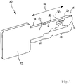
- FIG. 1 shows a lock cylinder key which is designated as a whole by the reference numeral 10.
- the lock cylinder key 10 has a key bow 12 and a key shaft 16 extending along an axial direction 14.
- the key shaft 16 has a half 18 axially facing away from the key head 12 (front half 18 of the key shaft 16) and a half 20 axially facing the key head 12 (rear half 20 of the key shaft 16).
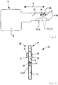
- the key shaft 16 has a stabilization insert 22 in its half 18 axially facing away from the key head 12 (see FIG Figure 2 ).
- the stabilization insert 22 has a higher strength than the material of the key shaft 16.
- the stabilization insert 22 is pressed into a passage 24 formed, in particular punched, in the key shaft 16.
- the stabilization insert 22 can be pressed in directly when the lock cylinder key 10 is punched.
- the passage 24 projects from one side 26 of the key shaft 16 to the other side 28 of the key shaft 16.
- the longitudinal axis 30 of the passage 24 is oriented transversely or orthogonally to the axial direction 14 (see FIG Figure 1 ).
- the cross section of the passage 24 can be reduced within the passage 24 (not shown). This can be done by means of a shoulder which is set back to form a key shank side surface 32, 34 and which reduces the cross section of the passage 24.
- the stabilization insert 22 can have a spherical or convex cross section.
- the stabilization insert 22 has a protrusion 36, 38 that protrudes on both sides from the key shaft 16 and is used for locking coding (see FIG Figures 2 and 3 and 6th ).
- This projection 36, 38 can interact with additional lock codes in the associated lock cylinder.
- the stabilization insert 22 can only have a protrusion 36, 38 protruding on one side or can be arranged flush or recessed in relation to the key shaft side surfaces 32, 34 (not shown).
- the key shaft 16 can have at least one further insert which is arranged axially between the key head 12 and the stabilizing insert 22 (not shown).
- the further use can take on further functions as a functional use.
- the further insert can have a projection protruding from the key shaft 16 on one or both sides and used for locking coding, a color coding, a pictogram and / or an RFID transponder, as described above.
- the side surfaces 32, 34 of the key shank 16 are oriented parallel to one another and are free of profiles. In other words, the side surfaces 32, 34 are flat and free from axial depressions or elevations.
- the key shank 16 has recesses 40, 41 (notches) serving for lock coding, a continuous outer edge 42 being formed in the area of the recesses 40 serving for lock coding.
- the continuous outer edge 42 is formed by a web 44 which extends in the axial direction 14 and to which the recesses 40, 41 for locking coding are arranged on both sides.
- Through the recesses 40, 41 is a two-row design of the recesses formed with the web 44 as an intermediate element (two rows of locking codes 40, 1 with an intermediate web 44).
- the web 44 is arranged in particular in the middle with respect to the material thickness of the key shaft 16.
- the lock cylinder key 10 is in the present case designed as a bit key (“conventional profile cylinder key”). As a bit key, the lock cylinder key 10 can only be inserted into an associated lock cylinder in one orientation.
- the cylinder lock key 10, in particular the key bow 12 and the key shaft 16, can have a material thickness of 1.5 mm to 2.5 mm, preferably 1.7 mm to 2.3 mm, more preferably 1.8 mm to 2.2 mm, even more preferably 2, 0mm.
- the lock cylinder key 10 is formed from a low-nickel metal or a low-nickel metal alloy, as described above.
- FIG 4 shows a further embodiment of a lock cylinder key, which is designated as a whole by the reference numeral 10.
- the present cylinder lock key 10 corresponds to a large extent to that in connection with Figure 1-3 described embodiment. To avoid repetition, reference is therefore made to the statements above.
- the lock cylinder key 10 is designed as a reversible key.
- the lock cylinder key 10 can be inserted into an associated lock cylinder in several, in the present case in two, orientations.
- the stabilization insert 22 can be in the front half 18 of the key shaft 16 or, as shown here, be arranged in the front third of the key shaft 16.
- the method for producing a cylinder lock key 10 with a key head 12 and a key shaft 16 axially extending from the key head 12 can proceed as follows:
- the cylinder lock key 10 is formed by a punching process, that is to say is given its shape by a punching process, which includes the key head 12 and the key shaft 16 (punched key blank).
- a stabilizing insert 22 with a higher strength than the material of the key shaft 16 is introduced into the half 18 of the key shaft 16 facing away from the key head 12. This is done in particular by pressing the stabilization insert 22 into the key shaft 16. It is also conceivable to introduce it into the front third of the key shaft 16.
- the passage 24 into which the stabilizing insert 22 is inserted is also formed during the punching process.
- a further insert can also be introduced into the key shank 16, in particular pressed into it.
- the further insert can take on additional functions as described above.
Landscapes
- Lock And Its Accessories (AREA)
Priority Applications (9)
| Application Number | Priority Date | Filing Date | Title |
|---|---|---|---|
| PL20183489T PL3739153T3 (pl) | 2017-11-09 | 2017-11-09 | Klucz wkładki zamka i sposób jego wytwarzania |
| SI201730891T SI3739153T1 (sl) | 2017-11-09 | 2017-11-09 | Ključ za cilindrično ključavnico in postopek za njegovo proizvodnjo |
| HUE20183489A HUE055569T2 (hu) | 2017-11-09 | 2017-11-09 | Zárhenger-kulcs és eljárás annak elõállítására |
| ES20183489T ES2887099T3 (es) | 2017-11-09 | 2017-11-09 | Llave de cilindro de cierre y procedimiento para su fabricación |
| EP20183489.2A EP3739153B1 (de) | 2017-11-09 | 2017-11-09 | Schliesszylinderschlüssel und verfahren zu dessen herstellung |
| PT20183489T PT3739153T (pt) | 2017-11-09 | 2017-11-09 | Chave de cilindro de frchadura e processo para o seu fabrico |
| RS20211147A RS62391B1 (sr) | 2017-11-09 | 2017-11-09 | Ključ za cilindar brave i postupak za njegovu proizvodnju |
| EP17200896.3A EP3483363B1 (de) | 2017-11-09 | 2017-11-09 | Schliesszylinderschlüssel und verfahren zu dessen herstellung |
| HRP20211463TT HRP20211463T1 (hr) | 2017-11-09 | 2017-11-09 | Ključ za cilindar brave i postupak njegove proizvodnje |
Applications Claiming Priority (1)
| Application Number | Priority Date | Filing Date | Title |
|---|---|---|---|
| EP17200896.3A EP3483363B1 (de) | 2017-11-09 | 2017-11-09 | Schliesszylinderschlüssel und verfahren zu dessen herstellung |
Related Child Applications (2)
| Application Number | Title | Priority Date | Filing Date |
|---|---|---|---|
| EP20183489.2A Division EP3739153B1 (de) | 2017-11-09 | 2017-11-09 | Schliesszylinderschlüssel und verfahren zu dessen herstellung |
| EP20183489.2A Division-Into EP3739153B1 (de) | 2017-11-09 | 2017-11-09 | Schliesszylinderschlüssel und verfahren zu dessen herstellung |
Publications (2)
| Publication Number | Publication Date |
|---|---|
| EP3483363A1 EP3483363A1 (de) | 2019-05-15 |
| EP3483363B1 true EP3483363B1 (de) | 2020-12-30 |
Family
ID=60301842
Family Applications (2)
| Application Number | Title | Priority Date | Filing Date |
|---|---|---|---|
| EP17200896.3A Active EP3483363B1 (de) | 2017-11-09 | 2017-11-09 | Schliesszylinderschlüssel und verfahren zu dessen herstellung |
| EP20183489.2A Active EP3739153B1 (de) | 2017-11-09 | 2017-11-09 | Schliesszylinderschlüssel und verfahren zu dessen herstellung |
Family Applications After (1)
| Application Number | Title | Priority Date | Filing Date |
|---|---|---|---|
| EP20183489.2A Active EP3739153B1 (de) | 2017-11-09 | 2017-11-09 | Schliesszylinderschlüssel und verfahren zu dessen herstellung |
Country Status (8)
| Country | Link |
|---|---|
| EP (2) | EP3483363B1 (pl) |
| ES (1) | ES2887099T3 (pl) |
| HR (1) | HRP20211463T1 (pl) |
| HU (1) | HUE055569T2 (pl) |
| PL (1) | PL3739153T3 (pl) |
| PT (1) | PT3739153T (pl) |
| RS (1) | RS62391B1 (pl) |
| SI (1) | SI3739153T1 (pl) |
Families Citing this family (1)
| Publication number | Priority date | Publication date | Assignee | Title |
|---|---|---|---|---|
| AT526389A1 (de) * | 2022-07-20 | 2024-02-15 | Evva Sicherheitstechnologie | Schlüssel für ein Zylinderschloss und Zylinderschloss |
Family Cites Families (11)
| Publication number | Priority date | Publication date | Assignee | Title |
|---|---|---|---|---|
| US103837A (en) * | 1870-06-07 | Improvement in door-keys | ||
| US89596A (en) * | 1869-05-04 | Improvement in door-keys | ||
| CH495488A (de) * | 1967-08-15 | 1970-08-31 | Dana Eugene | Schlüssel sowie Verfahren zu seiner Herstellung |
| AT371532B (de) * | 1978-12-15 | 1983-07-11 | Grundmann Gmbh Geb | Flachschluessel |
| JPH02128078A (ja) * | 1988-11-07 | 1990-05-16 | Masaji Terada | 鍵の製造方法及び鍵 |
| JPH04319034A (ja) * | 1991-04-17 | 1992-11-10 | Tokai Rika Co Ltd | 内溝キーの製造方法 |
| CN201826608U (zh) * | 2010-04-26 | 2011-05-11 | 杨子健 | 复合钥匙 |
| DE102010029167B4 (de) | 2010-05-20 | 2012-03-01 | Bks Gmbh | Profilzylinderschlüssel |
| US20150114058A1 (en) * | 2011-08-26 | 2015-04-30 | Ernst Keller | Rotary Locking Cylinder and Security Key |
| AT514254B1 (de) * | 2013-05-14 | 2016-06-15 | Evva Sicherheitstechnologie | Verfahren zur Herstellung eines Schlüssels sowie eine Vorrichtung zur Durchführung des Verfahrens |
| DE102013012102B4 (de) * | 2013-07-16 | 2015-10-15 | Assa Abloy Sicherheitstechnik Gmbh | Schloss-Schlüssel-System |
-
2017
- 2017-11-09 RS RS20211147A patent/RS62391B1/sr unknown
- 2017-11-09 ES ES20183489T patent/ES2887099T3/es active Active
- 2017-11-09 SI SI201730891T patent/SI3739153T1/sl unknown
- 2017-11-09 HU HUE20183489A patent/HUE055569T2/hu unknown
- 2017-11-09 HR HRP20211463TT patent/HRP20211463T1/hr unknown
- 2017-11-09 PL PL20183489T patent/PL3739153T3/pl unknown
- 2017-11-09 EP EP17200896.3A patent/EP3483363B1/de active Active
- 2017-11-09 EP EP20183489.2A patent/EP3739153B1/de active Active
- 2017-11-09 PT PT20183489T patent/PT3739153T/pt unknown
Non-Patent Citations (1)
| Title |
|---|
| None * |
Also Published As
| Publication number | Publication date |
|---|---|
| EP3739153B1 (de) | 2021-06-16 |
| HUE055569T2 (hu) | 2021-12-28 |
| PT3739153T (pt) | 2021-09-06 |
| PL3739153T3 (pl) | 2021-12-13 |
| HRP20211463T1 (hr) | 2022-02-04 |
| EP3739153A1 (de) | 2020-11-18 |
| RS62391B1 (sr) | 2021-10-29 |
| SI3739153T1 (sl) | 2021-10-29 |
| EP3483363A1 (de) | 2019-05-15 |
| ES2887099T3 (es) | 2021-12-21 |
Similar Documents
| Publication | Publication Date | Title |
|---|---|---|
| EP2314807B1 (de) | Schliesssystem | |
| DE4035934C2 (de) | Aus Schlüssel und Schließzylinder bestehende Schließvorrichtung | |
| DE8035193U1 (de) | Schluessel fuer einen schliesszylinder | |
| EP1420919B1 (de) | Spannfutter für werkzeuge, insbesondere schraubendreherbits | |
| EP2803793A2 (de) | Schließzylinder mit Zugstift, an dem ein von der Breitseite des Schlüssels abragender Vorsprung angreift | |
| DE69704774T2 (de) | Verfahren zum herstellen einer versteifungsleiste für eine extrudierte wischlippe eines scheibenwischers | |
| EP3739153B1 (de) | Schliesszylinderschlüssel und verfahren zu dessen herstellung | |
| EP0662733B1 (de) | Kontaktfeder-Anordnung | |
| EP1048804B1 (de) | Schliesssystem | |
| EP3483365B1 (de) | Schlüssel zur betätigung eines schliesszylinders und schliesssystem mit schlüssel und schliesszylinder | |
| DE3736129A1 (de) | Schliesszylinder mit stiftzuhaltungen | |
| EP2759666B1 (de) | Beschlaganordnung mit einem Profilelement | |
| EP3604718B1 (de) | Schlüssel zur betätigung eines schliesszylinders | |
| EP3483364B1 (de) | Schlüssel zur betätigung eines schliesszylinders und schliesssystem mit schlüssel und schliesszylinder | |
| AT412812B (de) | Gleitlagerschale | |
| DE4437712B4 (de) | Schließeinrichtung mit einem Zylinderschloß und einem Wendeflachschlüssel | |
| EP2295686A1 (de) | Schließzapfen für einen Fenster- oder Türverriegelungsbeschlag | |
| DE102008014527A1 (de) | Werkzeuggriff | |
| EP0478886B1 (de) | Zugglied | |
| EP2295685B1 (de) | Schließzapfen für einen Fenster- oder Türverriegelungsbeschlag | |
| EP3640416B1 (de) | Schlüssel für einen schliesszylinder und schliesssystem | |
| EP3489451B1 (de) | Verbund eines rollladenkastens mit einem rahmen | |
| DE102007041964B3 (de) | Schloss-Schlüsselkombination | |
| EP3640417B1 (de) | Schlüssel für einen schliesszylinder | |
| DE19640119C2 (de) | Biegewerkzeug |
Legal Events
| Date | Code | Title | Description |
|---|---|---|---|
| PUAI | Public reference made under article 153(3) epc to a published international application that has entered the european phase |
Free format text: ORIGINAL CODE: 0009012 |
|
| STAA | Information on the status of an ep patent application or granted ep patent |
Free format text: STATUS: REQUEST FOR EXAMINATION WAS MADE |
|
| 17P | Request for examination filed |
Effective date: 20180515 |
|
| AK | Designated contracting states |
Kind code of ref document: A1 Designated state(s): AL AT BE BG CH CY CZ DE DK EE ES FI FR GB GR HR HU IE IS IT LI LT LU LV MC MK MT NL NO PL PT RO RS SE SI SK SM TR |
|
| AX | Request for extension of the european patent |
Extension state: BA ME |
|
| GRAP | Despatch of communication of intention to grant a patent |
Free format text: ORIGINAL CODE: EPIDOSNIGR1 |
|
| STAA | Information on the status of an ep patent application or granted ep patent |
Free format text: STATUS: GRANT OF PATENT IS INTENDED |
|
| INTG | Intention to grant announced |
Effective date: 20191203 |
|
| GRAJ | Information related to disapproval of communication of intention to grant by the applicant or resumption of examination proceedings by the epo deleted |
Free format text: ORIGINAL CODE: EPIDOSDIGR1 |
|
| STAA | Information on the status of an ep patent application or granted ep patent |
Free format text: STATUS: REQUEST FOR EXAMINATION WAS MADE |
|
| INTC | Intention to grant announced (deleted) | ||
| GRAP | Despatch of communication of intention to grant a patent |
Free format text: ORIGINAL CODE: EPIDOSNIGR1 |
|
| STAA | Information on the status of an ep patent application or granted ep patent |
Free format text: STATUS: GRANT OF PATENT IS INTENDED |
|
| INTG | Intention to grant announced |
Effective date: 20200622 |
|
| GRAS | Grant fee paid |
Free format text: ORIGINAL CODE: EPIDOSNIGR3 |
|
| GRAA | (expected) grant |
Free format text: ORIGINAL CODE: 0009210 |
|
| STAA | Information on the status of an ep patent application or granted ep patent |
Free format text: STATUS: THE PATENT HAS BEEN GRANTED |
|
| AK | Designated contracting states |
Kind code of ref document: B1 Designated state(s): AL AT BE BG CH CY CZ DE DK EE ES FI FR GB GR HR HU IE IS IT LI LT LU LV MC MK MT NL NO PL PT RO RS SE SI SK SM TR |
|
| REG | Reference to a national code |
Ref country code: GB Ref legal event code: FG4D Free format text: NOT ENGLISH |
|
| REG | Reference to a national code |
Ref country code: DE Ref legal event code: R096 Ref document number: 502017008827 Country of ref document: DE |
|
| REG | Reference to a national code |
Ref country code: AT Ref legal event code: REF Ref document number: 1350066 Country of ref document: AT Kind code of ref document: T Effective date: 20210115 |
|
| REG | Reference to a national code |
Ref country code: IE Ref legal event code: FG4D Free format text: LANGUAGE OF EP DOCUMENT: GERMAN |
|
| REG | Reference to a national code |
Ref country code: NL Ref legal event code: FP |
|
| PG25 | Lapsed in a contracting state [announced via postgrant information from national office to epo] |
Ref country code: GR Free format text: LAPSE BECAUSE OF FAILURE TO SUBMIT A TRANSLATION OF THE DESCRIPTION OR TO PAY THE FEE WITHIN THE PRESCRIBED TIME-LIMIT Effective date: 20210331 Ref country code: FI Free format text: LAPSE BECAUSE OF FAILURE TO SUBMIT A TRANSLATION OF THE DESCRIPTION OR TO PAY THE FEE WITHIN THE PRESCRIBED TIME-LIMIT Effective date: 20201230 Ref country code: NO Free format text: LAPSE BECAUSE OF FAILURE TO SUBMIT A TRANSLATION OF THE DESCRIPTION OR TO PAY THE FEE WITHIN THE PRESCRIBED TIME-LIMIT Effective date: 20210330 Ref country code: RS Free format text: LAPSE BECAUSE OF FAILURE TO SUBMIT A TRANSLATION OF THE DESCRIPTION OR TO PAY THE FEE WITHIN THE PRESCRIBED TIME-LIMIT Effective date: 20201230 |
|
| PG25 | Lapsed in a contracting state [announced via postgrant information from national office to epo] |
Ref country code: SE Free format text: LAPSE BECAUSE OF FAILURE TO SUBMIT A TRANSLATION OF THE DESCRIPTION OR TO PAY THE FEE WITHIN THE PRESCRIBED TIME-LIMIT Effective date: 20201230 Ref country code: BG Free format text: LAPSE BECAUSE OF FAILURE TO SUBMIT A TRANSLATION OF THE DESCRIPTION OR TO PAY THE FEE WITHIN THE PRESCRIBED TIME-LIMIT Effective date: 20210330 Ref country code: LV Free format text: LAPSE BECAUSE OF FAILURE TO SUBMIT A TRANSLATION OF THE DESCRIPTION OR TO PAY THE FEE WITHIN THE PRESCRIBED TIME-LIMIT Effective date: 20201230 |
|
| PG25 | Lapsed in a contracting state [announced via postgrant information from national office to epo] |
Ref country code: HR Free format text: LAPSE BECAUSE OF FAILURE TO SUBMIT A TRANSLATION OF THE DESCRIPTION OR TO PAY THE FEE WITHIN THE PRESCRIBED TIME-LIMIT Effective date: 20201230 |
|
| REG | Reference to a national code |
Ref country code: LT Ref legal event code: MG9D |
|
| PG25 | Lapsed in a contracting state [announced via postgrant information from national office to epo] |
Ref country code: PT Free format text: LAPSE BECAUSE OF FAILURE TO SUBMIT A TRANSLATION OF THE DESCRIPTION OR TO PAY THE FEE WITHIN THE PRESCRIBED TIME-LIMIT Effective date: 20210430 Ref country code: SK Free format text: LAPSE BECAUSE OF FAILURE TO SUBMIT A TRANSLATION OF THE DESCRIPTION OR TO PAY THE FEE WITHIN THE PRESCRIBED TIME-LIMIT Effective date: 20201230 Ref country code: RO Free format text: LAPSE BECAUSE OF FAILURE TO SUBMIT A TRANSLATION OF THE DESCRIPTION OR TO PAY THE FEE WITHIN THE PRESCRIBED TIME-LIMIT Effective date: 20201230 Ref country code: EE Free format text: LAPSE BECAUSE OF FAILURE TO SUBMIT A TRANSLATION OF THE DESCRIPTION OR TO PAY THE FEE WITHIN THE PRESCRIBED TIME-LIMIT Effective date: 20201230 Ref country code: CZ Free format text: LAPSE BECAUSE OF FAILURE TO SUBMIT A TRANSLATION OF THE DESCRIPTION OR TO PAY THE FEE WITHIN THE PRESCRIBED TIME-LIMIT Effective date: 20201230 Ref country code: LT Free format text: LAPSE BECAUSE OF FAILURE TO SUBMIT A TRANSLATION OF THE DESCRIPTION OR TO PAY THE FEE WITHIN THE PRESCRIBED TIME-LIMIT Effective date: 20201230 |
|
| PG25 | Lapsed in a contracting state [announced via postgrant information from national office to epo] |
Ref country code: PL Free format text: LAPSE BECAUSE OF FAILURE TO SUBMIT A TRANSLATION OF THE DESCRIPTION OR TO PAY THE FEE WITHIN THE PRESCRIBED TIME-LIMIT Effective date: 20201230 |
|
| PG25 | Lapsed in a contracting state [announced via postgrant information from national office to epo] |
Ref country code: IS Free format text: LAPSE BECAUSE OF FAILURE TO SUBMIT A TRANSLATION OF THE DESCRIPTION OR TO PAY THE FEE WITHIN THE PRESCRIBED TIME-LIMIT Effective date: 20210430 |
|
| REG | Reference to a national code |
Ref country code: DE Ref legal event code: R097 Ref document number: 502017008827 Country of ref document: DE |
|
| PG25 | Lapsed in a contracting state [announced via postgrant information from national office to epo] |
Ref country code: IT Free format text: LAPSE BECAUSE OF FAILURE TO SUBMIT A TRANSLATION OF THE DESCRIPTION OR TO PAY THE FEE WITHIN THE PRESCRIBED TIME-LIMIT Effective date: 20201230 Ref country code: AL Free format text: LAPSE BECAUSE OF FAILURE TO SUBMIT A TRANSLATION OF THE DESCRIPTION OR TO PAY THE FEE WITHIN THE PRESCRIBED TIME-LIMIT Effective date: 20201230 |
|
| PLBE | No opposition filed within time limit |
Free format text: ORIGINAL CODE: 0009261 |
|
| STAA | Information on the status of an ep patent application or granted ep patent |
Free format text: STATUS: NO OPPOSITION FILED WITHIN TIME LIMIT |
|
| PG25 | Lapsed in a contracting state [announced via postgrant information from national office to epo] |
Ref country code: DK Free format text: LAPSE BECAUSE OF FAILURE TO SUBMIT A TRANSLATION OF THE DESCRIPTION OR TO PAY THE FEE WITHIN THE PRESCRIBED TIME-LIMIT Effective date: 20201230 |
|
| 26N | No opposition filed |
Effective date: 20211001 |
|
| REG | Reference to a national code |
Ref country code: DE Ref legal event code: R082 Ref document number: 502017008827 Country of ref document: DE |
|
| PG25 | Lapsed in a contracting state [announced via postgrant information from national office to epo] |
Ref country code: ES Free format text: LAPSE BECAUSE OF FAILURE TO SUBMIT A TRANSLATION OF THE DESCRIPTION OR TO PAY THE FEE WITHIN THE PRESCRIBED TIME-LIMIT Effective date: 20201230 |
|
| PG25 | Lapsed in a contracting state [announced via postgrant information from national office to epo] |
Ref country code: SI Free format text: LAPSE BECAUSE OF FAILURE TO SUBMIT A TRANSLATION OF THE DESCRIPTION OR TO PAY THE FEE WITHIN THE PRESCRIBED TIME-LIMIT Effective date: 20201230 |
|
| PG25 | Lapsed in a contracting state [announced via postgrant information from national office to epo] |
Ref country code: IS Free format text: LAPSE BECAUSE OF FAILURE TO SUBMIT A TRANSLATION OF THE DESCRIPTION OR TO PAY THE FEE WITHIN THE PRESCRIBED TIME-LIMIT Effective date: 20210430 |
|
| PG25 | Lapsed in a contracting state [announced via postgrant information from national office to epo] |
Ref country code: MC Free format text: LAPSE BECAUSE OF FAILURE TO SUBMIT A TRANSLATION OF THE DESCRIPTION OR TO PAY THE FEE WITHIN THE PRESCRIBED TIME-LIMIT Effective date: 20201230 |
|
| REG | Reference to a national code |
Ref country code: CH Ref legal event code: PL |
|
| GBPC | Gb: european patent ceased through non-payment of renewal fee |
Effective date: 20211109 |
|
| PG25 | Lapsed in a contracting state [announced via postgrant information from national office to epo] |
Ref country code: LU Free format text: LAPSE BECAUSE OF NON-PAYMENT OF DUE FEES Effective date: 20211109 |
|
| PG25 | Lapsed in a contracting state [announced via postgrant information from national office to epo] |
Ref country code: LI Free format text: LAPSE BECAUSE OF NON-PAYMENT OF DUE FEES Effective date: 20211130 Ref country code: CH Free format text: LAPSE BECAUSE OF NON-PAYMENT OF DUE FEES Effective date: 20211130 |
|
| PG25 | Lapsed in a contracting state [announced via postgrant information from national office to epo] |
Ref country code: IE Free format text: LAPSE BECAUSE OF NON-PAYMENT OF DUE FEES Effective date: 20211109 Ref country code: GB Free format text: LAPSE BECAUSE OF NON-PAYMENT OF DUE FEES Effective date: 20211109 |
|
| P01 | Opt-out of the competence of the unified patent court (upc) registered |
Effective date: 20230509 |
|
| PG25 | Lapsed in a contracting state [announced via postgrant information from national office to epo] |
Ref country code: CY Free format text: LAPSE BECAUSE OF FAILURE TO SUBMIT A TRANSLATION OF THE DESCRIPTION OR TO PAY THE FEE WITHIN THE PRESCRIBED TIME-LIMIT Effective date: 20201230 |
|
| PG25 | Lapsed in a contracting state [announced via postgrant information from national office to epo] |
Ref country code: SM Free format text: LAPSE BECAUSE OF FAILURE TO SUBMIT A TRANSLATION OF THE DESCRIPTION OR TO PAY THE FEE WITHIN THE PRESCRIBED TIME-LIMIT Effective date: 20201230 Ref country code: HU Free format text: LAPSE BECAUSE OF FAILURE TO SUBMIT A TRANSLATION OF THE DESCRIPTION OR TO PAY THE FEE WITHIN THE PRESCRIBED TIME-LIMIT; INVALID AB INITIO Effective date: 20171109 |
|
| PG25 | Lapsed in a contracting state [announced via postgrant information from national office to epo] |
Ref country code: MK Free format text: LAPSE BECAUSE OF FAILURE TO SUBMIT A TRANSLATION OF THE DESCRIPTION OR TO PAY THE FEE WITHIN THE PRESCRIBED TIME-LIMIT Effective date: 20201230 |
|
| PG25 | Lapsed in a contracting state [announced via postgrant information from national office to epo] |
Ref country code: TR Free format text: LAPSE BECAUSE OF FAILURE TO SUBMIT A TRANSLATION OF THE DESCRIPTION OR TO PAY THE FEE WITHIN THE PRESCRIBED TIME-LIMIT Effective date: 20201230 |
|
| PG25 | Lapsed in a contracting state [announced via postgrant information from national office to epo] |
Ref country code: MT Free format text: LAPSE BECAUSE OF FAILURE TO SUBMIT A TRANSLATION OF THE DESCRIPTION OR TO PAY THE FEE WITHIN THE PRESCRIBED TIME-LIMIT Effective date: 20201230 |
|
| PGFP | Annual fee paid to national office [announced via postgrant information from national office to epo] |
Ref country code: NL Payment date: 20251119 Year of fee payment: 9 |
|
| PGFP | Annual fee paid to national office [announced via postgrant information from national office to epo] |
Ref country code: DE Payment date: 20251119 Year of fee payment: 9 |
|
| PGFP | Annual fee paid to national office [announced via postgrant information from national office to epo] |
Ref country code: AT Payment date: 20251120 Year of fee payment: 9 |
|
| PGFP | Annual fee paid to national office [announced via postgrant information from national office to epo] |
Ref country code: FR Payment date: 20251126 Year of fee payment: 9 |
|
| PGFP | Annual fee paid to national office [announced via postgrant information from national office to epo] |
Ref country code: BE Payment date: 20251119 Year of fee payment: 9 |