EP3481576B1 - Verwendung einer legierung als hartlötlegierung für eine elektrische schalterlötverbindung, elektrische schalterlötverbindung, elektrischer schalter und verfahren zur herstellung einer elektrischen schalterlötverbindung - Google Patents
Verwendung einer legierung als hartlötlegierung für eine elektrische schalterlötverbindung, elektrische schalterlötverbindung, elektrischer schalter und verfahren zur herstellung einer elektrischen schalterlötverbindung Download PDFInfo
- Publication number
- EP3481576B1 EP3481576B1 EP17735156.6A EP17735156A EP3481576B1 EP 3481576 B1 EP3481576 B1 EP 3481576B1 EP 17735156 A EP17735156 A EP 17735156A EP 3481576 B1 EP3481576 B1 EP 3481576B1
- Authority
- EP
- European Patent Office
- Prior art keywords
- alloy
- brazing
- electric switch
- group
- braze joint
- Prior art date
- Legal status (The legal status is an assumption and is not a legal conclusion. Google has not performed a legal analysis and makes no representation as to the accuracy of the status listed.)
- Active
Links
Images


Classifications
-
- B—PERFORMING OPERATIONS; TRANSPORTING
- B23—MACHINE TOOLS; METAL-WORKING NOT OTHERWISE PROVIDED FOR
- B23K—SOLDERING OR UNSOLDERING; WELDING; CLADDING OR PLATING BY SOLDERING OR WELDING; CUTTING BY APPLYING HEAT LOCALLY, e.g. FLAME CUTTING; WORKING BY LASER BEAM
- B23K35/00—Rods, electrodes, materials, or media, for use in soldering, welding, or cutting
- B23K35/22—Rods, electrodes, materials, or media, for use in soldering, welding, or cutting characterised by the composition or nature of the material
- B23K35/24—Selection of soldering or welding materials proper
- B23K35/30—Selection of soldering or welding materials proper with the principal constituent melting at less than 1550 degrees C
- B23K35/302—Cu as the principal constituent
-
- B—PERFORMING OPERATIONS; TRANSPORTING
- B23—MACHINE TOOLS; METAL-WORKING NOT OTHERWISE PROVIDED FOR
- B23K—SOLDERING OR UNSOLDERING; WELDING; CLADDING OR PLATING BY SOLDERING OR WELDING; CUTTING BY APPLYING HEAT LOCALLY, e.g. FLAME CUTTING; WORKING BY LASER BEAM
- B23K1/00—Soldering, e.g. brazing, or unsoldering
- B23K1/0008—Soldering, e.g. brazing, or unsoldering specially adapted for particular articles or work
- B23K1/0016—Brazing of electronic components
-
- B—PERFORMING OPERATIONS; TRANSPORTING
- B23—MACHINE TOOLS; METAL-WORKING NOT OTHERWISE PROVIDED FOR
- B23K—SOLDERING OR UNSOLDERING; WELDING; CLADDING OR PLATING BY SOLDERING OR WELDING; CUTTING BY APPLYING HEAT LOCALLY, e.g. FLAME CUTTING; WORKING BY LASER BEAM
- B23K35/00—Rods, electrodes, materials, or media, for use in soldering, welding, or cutting
- B23K35/02—Rods, electrodes, materials, or media, for use in soldering, welding, or cutting characterised by mechanical features, e.g. shape
- B23K35/0222—Rods, electrodes, materials, or media, for use in soldering, welding, or cutting characterised by mechanical features, e.g. shape for use in soldering, brazing
- B23K35/0233—Sheets, foils
- B23K35/0238—Sheets, foils layered
-
- B—PERFORMING OPERATIONS; TRANSPORTING
- B23—MACHINE TOOLS; METAL-WORKING NOT OTHERWISE PROVIDED FOR
- B23K—SOLDERING OR UNSOLDERING; WELDING; CLADDING OR PLATING BY SOLDERING OR WELDING; CUTTING BY APPLYING HEAT LOCALLY, e.g. FLAME CUTTING; WORKING BY LASER BEAM
- B23K35/00—Rods, electrodes, materials, or media, for use in soldering, welding, or cutting
- B23K35/22—Rods, electrodes, materials, or media, for use in soldering, welding, or cutting characterised by the composition or nature of the material
- B23K35/24—Selection of soldering or welding materials proper
- B23K35/26—Selection of soldering or welding materials proper with the principal constituent melting at less than 400 degrees C
- B23K35/262—Sn as the principal constituent
-
- B—PERFORMING OPERATIONS; TRANSPORTING
- B23—MACHINE TOOLS; METAL-WORKING NOT OTHERWISE PROVIDED FOR
- B23K—SOLDERING OR UNSOLDERING; WELDING; CLADDING OR PLATING BY SOLDERING OR WELDING; CUTTING BY APPLYING HEAT LOCALLY, e.g. FLAME CUTTING; WORKING BY LASER BEAM
- B23K35/00—Rods, electrodes, materials, or media, for use in soldering, welding, or cutting
- B23K35/22—Rods, electrodes, materials, or media, for use in soldering, welding, or cutting characterised by the composition or nature of the material
- B23K35/24—Selection of soldering or welding materials proper
- B23K35/26—Selection of soldering or welding materials proper with the principal constituent melting at less than 400 degrees C
- B23K35/264—Bi as the principal constituent
-
- B—PERFORMING OPERATIONS; TRANSPORTING
- B23—MACHINE TOOLS; METAL-WORKING NOT OTHERWISE PROVIDED FOR
- B23K—SOLDERING OR UNSOLDERING; WELDING; CLADDING OR PLATING BY SOLDERING OR WELDING; CUTTING BY APPLYING HEAT LOCALLY, e.g. FLAME CUTTING; WORKING BY LASER BEAM
- B23K35/00—Rods, electrodes, materials, or media, for use in soldering, welding, or cutting
- B23K35/22—Rods, electrodes, materials, or media, for use in soldering, welding, or cutting characterised by the composition or nature of the material
- B23K35/24—Selection of soldering or welding materials proper
- B23K35/26—Selection of soldering or welding materials proper with the principal constituent melting at less than 400 degrees C
- B23K35/266—Cd as the principal constituent
-
- B—PERFORMING OPERATIONS; TRANSPORTING
- B23—MACHINE TOOLS; METAL-WORKING NOT OTHERWISE PROVIDED FOR
- B23K—SOLDERING OR UNSOLDERING; WELDING; CLADDING OR PLATING BY SOLDERING OR WELDING; CUTTING BY APPLYING HEAT LOCALLY, e.g. FLAME CUTTING; WORKING BY LASER BEAM
- B23K35/00—Rods, electrodes, materials, or media, for use in soldering, welding, or cutting
- B23K35/22—Rods, electrodes, materials, or media, for use in soldering, welding, or cutting characterised by the composition or nature of the material
- B23K35/24—Selection of soldering or welding materials proper
- B23K35/28—Selection of soldering or welding materials proper with the principal constituent melting at less than 950 degrees C
- B23K35/282—Zn as the principal constituent
-
- B—PERFORMING OPERATIONS; TRANSPORTING
- B23—MACHINE TOOLS; METAL-WORKING NOT OTHERWISE PROVIDED FOR
- B23K—SOLDERING OR UNSOLDERING; WELDING; CLADDING OR PLATING BY SOLDERING OR WELDING; CUTTING BY APPLYING HEAT LOCALLY, e.g. FLAME CUTTING; WORKING BY LASER BEAM
- B23K35/00—Rods, electrodes, materials, or media, for use in soldering, welding, or cutting
- B23K35/22—Rods, electrodes, materials, or media, for use in soldering, welding, or cutting characterised by the composition or nature of the material
- B23K35/24—Selection of soldering or welding materials proper
- B23K35/30—Selection of soldering or welding materials proper with the principal constituent melting at less than 1550 degrees C
- B23K35/3006—Ag as the principal constituent
-
- B—PERFORMING OPERATIONS; TRANSPORTING
- B23—MACHINE TOOLS; METAL-WORKING NOT OTHERWISE PROVIDED FOR
- B23K—SOLDERING OR UNSOLDERING; WELDING; CLADDING OR PLATING BY SOLDERING OR WELDING; CUTTING BY APPLYING HEAT LOCALLY, e.g. FLAME CUTTING; WORKING BY LASER BEAM
- B23K35/00—Rods, electrodes, materials, or media, for use in soldering, welding, or cutting
- B23K35/22—Rods, electrodes, materials, or media, for use in soldering, welding, or cutting characterised by the composition or nature of the material
- B23K35/24—Selection of soldering or welding materials proper
- B23K35/30—Selection of soldering or welding materials proper with the principal constituent melting at less than 1550 degrees C
- B23K35/3026—Mn as the principal constituent
-
- B—PERFORMING OPERATIONS; TRANSPORTING
- B23—MACHINE TOOLS; METAL-WORKING NOT OTHERWISE PROVIDED FOR
- B23K—SOLDERING OR UNSOLDERING; WELDING; CLADDING OR PLATING BY SOLDERING OR WELDING; CUTTING BY APPLYING HEAT LOCALLY, e.g. FLAME CUTTING; WORKING BY LASER BEAM
- B23K35/00—Rods, electrodes, materials, or media, for use in soldering, welding, or cutting
- B23K35/22—Rods, electrodes, materials, or media, for use in soldering, welding, or cutting characterised by the composition or nature of the material
- B23K35/24—Selection of soldering or welding materials proper
- B23K35/30—Selection of soldering or welding materials proper with the principal constituent melting at less than 1550 degrees C
- B23K35/3033—Ni as the principal constituent
-
- B—PERFORMING OPERATIONS; TRANSPORTING
- B32—LAYERED PRODUCTS
- B32B—LAYERED PRODUCTS, i.e. PRODUCTS BUILT-UP OF STRATA OF FLAT OR NON-FLAT, e.g. CELLULAR OR HONEYCOMB, FORM
- B32B15/00—Layered products comprising a layer of metal
-
- B—PERFORMING OPERATIONS; TRANSPORTING
- B32—LAYERED PRODUCTS
- B32B—LAYERED PRODUCTS, i.e. PRODUCTS BUILT-UP OF STRATA OF FLAT OR NON-FLAT, e.g. CELLULAR OR HONEYCOMB, FORM
- B32B15/00—Layered products comprising a layer of metal
- B32B15/01—Layered products comprising a layer of metal all layers being exclusively metallic
-
- C—CHEMISTRY; METALLURGY
- C22—METALLURGY; FERROUS OR NON-FERROUS ALLOYS; TREATMENT OF ALLOYS OR NON-FERROUS METALS
- C22C—ALLOYS
- C22C30/00—Alloys containing less than 50% by weight of each constituent
- C22C30/02—Alloys containing less than 50% by weight of each constituent containing copper
-
- C—CHEMISTRY; METALLURGY
- C22—METALLURGY; FERROUS OR NON-FERROUS ALLOYS; TREATMENT OF ALLOYS OR NON-FERROUS METALS
- C22C—ALLOYS
- C22C30/00—Alloys containing less than 50% by weight of each constituent
- C22C30/06—Alloys containing less than 50% by weight of each constituent containing zinc
-
- C—CHEMISTRY; METALLURGY
- C22—METALLURGY; FERROUS OR NON-FERROUS ALLOYS; TREATMENT OF ALLOYS OR NON-FERROUS METALS
- C22C—ALLOYS
- C22C5/00—Alloys based on noble metals
- C22C5/06—Alloys based on silver
-
- C—CHEMISTRY; METALLURGY
- C22—METALLURGY; FERROUS OR NON-FERROUS ALLOYS; TREATMENT OF ALLOYS OR NON-FERROUS METALS
- C22C—ALLOYS
- C22C9/00—Alloys based on copper
-
- B—PERFORMING OPERATIONS; TRANSPORTING
- B23—MACHINE TOOLS; METAL-WORKING NOT OTHERWISE PROVIDED FOR
- B23K—SOLDERING OR UNSOLDERING; WELDING; CLADDING OR PLATING BY SOLDERING OR WELDING; CUTTING BY APPLYING HEAT LOCALLY, e.g. FLAME CUTTING; WORKING BY LASER BEAM
- B23K2101/00—Articles made by soldering, welding or cutting
- B23K2101/36—Electric or electronic devices
Definitions
- Embodiments of the present disclosure relate to a use of an alloy as a brazing alloy for an electric switch braze joint, an electric switch braze joint, an electric switch and a method of producing an electric switch braze joint.
- An electric switch usually has two conductive pieces (contacts). For closing (breaking) the circuit the contacts touch and for opening (breaking) the circuit the contacts separate.
- the conductive pieces are usually connected to an external circuit via carriers (contact carriers).
- the connection between a contact and a carrier can, for example, be made by brazing.
- the material of a contact of an electric switch needs to meet specific requirements. Besides the properties for good contacting, such as high arc erosion resistance, low contact resistance and, depending on the switch type, good arc moving properties and good arc extinguishing capability, the contact material should satisfy further physical, mechanical, and chemical properties, such as high electrical and thermal conductivity, sufficient hardness to resist abrasive wear and mechanical strength, high corrosion resistance. Furthermore, the contact material should have good mechanical workability, sufficient hardness to resist to abrasive wear, mechanical strength. In addition, the contact material should be environmentally friendly and a low-cost material. For this reason, the choice of possible contact materials for electric switches is limited. However, there is hardly any material which meets all of the above-mentioned requirements. Typically, as contact materials in low voltage applications, silver (Ag) based composite materials, such as Ag-metal oxides, are used. Ag-based composite materials exhibit very good contact and switching properties, such as high resistance against welding, low contact resistance and high arc erosion resistance.
- the carrier material should exhibit high electrical and thermal conductivity, good mechanical strength even at elevated temperatures and a high resistance against corrosion.
- copper (Cu) based materials are used as carrier material.
- brazing materials For bonding of the contact to the carrier, various brazing materials can be used. Most of the commonly used brazing materials, such as Cu- and Ag- based brazing materials, exhibit insufficient wetting properties on Ag-metal oxide (in the following also referred to as Ag-MeO) based contact materials. Hence, for improving the wetting behavior, a pure silver backing layer is commonly used to bond the contact material with the carrier material.
- Ag-MeO Ag-metal oxide
- Fig. 1 a schematic assembly of a braze joint is exemplarily shown.
- the assembly 11 includes a contact material 2, a carrier material 3, a silver backing layer 12 and a brazing alloy 14.
- the silver backing layer 12 is used for ensuring sufficient wetting of the brazing alloy 14 on the contact material 2.
- the brazing alloy 14 melts and joins the carrier material 3 and the silver backing layer 12 to form a braze joint between the carrier material 3 and ultimately the contact material 2.
- JP2003055058A discloses a ceramic body consisting essentially of aluminum nitride or silicon nitride and the copper plate are laminated via a brazing filler metal containing 50 to 89% silver, 1 to 30% copper, 0.05 to 0.7% bismuth and 10 to 30% at least one of active metal selected from titanium, zirconium and hafnium as metallic components and joined by pressurizing under a pressure of ⁇ 1.0 MPa in a nitrogen atmosphere containing 100 to 1000 ppm oxygen at ⁇ 5.5°C temperature rising rate and temperature descending rate. It is preferable for the brazing filler metal to contain further 0.5 to 30% tin.
- SU407691A1 discloses solder for soldering metal with metal and metal with ceramics containing silver, copper, nickel, characterized in that, in order to increase the strength and heat resistance of soldered joints, molybdenum is introduced in its amount in the amount of 0.1 - 1%, and the remaining components are taken in the following correlation, % copper 25-30; nickel 0.1-1; silver is the rest.
- DE3011821A1 discloses A method for soldering a silver-containing metal part to a further metal part consisting of copper, a copper alloy or copper or alloy and steel, thereby characterized in that a layer of AgP and AgCd is inserted between both metal parts after the two metal parts are cleaned as a brazing material and then melted at a brazing temperature.
- an alloy as a brazing alloy for an electric switch braze joint, an electric switch braze joint and a method of producing an electric switch braze joint are provided.
- an alloy as a brazing alloy for an electric switch braze joint.
- the alloy composition consists of at least one element selected from each of group I and group II listed below, the balance being impurities and at least one of Ag, Cu, and Zn: group I: Cd, Mn, Ni, P, Sb, Si, Sn, Ti, and oxides thereof in a total amount of 0.5 to 45.0 wt.%; and group II: Bi, Mo, Te, W, and oxides thereof, oxides of Cu and Zn in a total amount of 0.1 to 15.0 wt.%.
- an electric switch braze joint includes an Ag-metal oxide contact material, a carrier material, and a brazed interlayer between the Ag-metal oxide contact material and the carrier material, the electric switch braze joint being formed by brazing with an alloy as a brazing alloy having a composition consisting of: at least one element selected from each of group I and group II listed below, the balance being impurities and at least one of Ag, Cu, and Zn (and preferably Ag and at least one of Cu and Zn, more preferably Ag and Cu, and more preferably at least one of Zn and P from group I): group I: Cd, Mn, Ni, P, Sb, Si, Sn, Ti, and oxides thereof in a total amount of 0.5 to 45.0 wt.%; and group II: Bi, Mo, Te, W, and oxides thereof, oxides of Cu and Zn in a total amount of 0.1 to 15.0 wt.%.
- group I Cd, Mn, Ni, P, Sb, Si, Sn, Ti, and
- an electric switch is provided.
- the electric switch has the above-described braze joint.
- a method of producing an electric switch braze joint includes providing an Ag-metal oxide contact material, providing a carrier material, providing an alloy between the Ag-metal oxide contact material and the carrier material, joining the Ag-metal oxide contact material and the carrier material by brazing with the alloy as a brazing alloy, wherein the alloy composition consists of: at least one element selected from each of group I and group II listed below, the balance being impurities and at least one of Ag, Cu, and Zn (and preferably Ag and at least one of Cu and Zn, more preferably Ag and Cu, and more preferably at least one of Zn and P from group I): group I: Cd, Mn, Ni, P, Sb, Si, Sn, Ti, and oxides thereof in a total amount of 0.5 to 45.0 wt.%; and group II: Bi, Mo, Te, W, and oxides thereof, oxides of Cu and Zn in a total amount of 0.1 to 15.0 wt
- a braze joint as used herein refers to a joining area which is obtained by joining at least two materials together by brazing.
- a braze joint as used herein comprises the materials to be joined and a brazing alloy.
- the materials to be joined are, for example, the Ag-metal oxide contact material and the carrier material.
- the braze joint includes an interlayer which is formed from the brazing alloy and at least one of the materials to be joined.
- the interlayer includes the brazing alloy and at least one of the materials to be joined as such or a compound formed of the brazing alloy and at least one of the materials to be joined.
- the interlayer may include an intermetallic phase or compound which is formed by the brazing alloy with at least one of the materials to be joined.
- the interlayer may further include a reaction layer which is formed by the brazing alloy with at least one of the materials to be joined at the interface between the brazing alloy and the respective material(s) to be joined.
- Brazing refers to a joining process of two (or more) materials to be joined using a brazing alloy which blends with the materials to be joined upon melting.
- the melting temperature of the brazing alloy is lower than the melting temperature of the materials to be joined.
- the liquefied/molten brazing alloy interacts with the materials to be joined and forms the braze joint during cooling.
- the interaction of the brazing alloy and the materials to be joined can be described by diffusion processes and formation processes of intermetallic phases and other compounds.
- the brazing may be performed in vacuum or protective atmosphere.
- a flux may be used during brazing in order to remove oxides from the brazing surfaces of the materials to be joined and to prevent the formation of oxides during brazing, thereby allowing a thorough wetting of the surfaces of the materials to be joined by the liquefied/molten brazing alloy.
- a fluxless braze is preferred .
- the fluxless brazing alloy for Ag and Cu base alloys may, for example, contain P.
- An electric switch as used herein refers to an electrical component that can disconnect and/or break an electrical circuit, for example for isolating a circuit portion, for interrupting the current or diverting it from one conductor to another.
- the electric switch has two contacts (conductive pieces) which are connected to an external circuit via carriers (contact carriers). For disconnecting and/or breaking the electrical circuit the contacts separate from each other. For closing the circuit the contacts touch each other.
- the electric switch as used herein comprises low- and medium-voltage switching devices.
- Low voltage as used herein refers to a voltage of less than 1 kV AC and medium voltage as used herein refers to a voltage of 1 kV AC to approximately 75 kV AC.
- Low voltage electrical switching devices comprise, for example, relays, installation and distribution switches, appliances, industrial controls, motor controls, and protective devices.
- Medium voltage electrical switching devices comprise, for example, load-break switches, motor controls, protective devices, and circuit-breakers for rolling stock.
- the electric switch may, for example, include a contactor which can be a low- or medium-voltage switching device.
- Impurities as used herein refer to typical unavoidable traces of elements which occur during the production process of brazing alloys. Such elements are, for example, : C, Fe, P, Si, and S.
- the upper limit of the total amount of impurities is 1.0 wt.%, preferably 0.5 wt.%, and more preferably 0.15 wt.%. These traces of elements do not contribute to or modify the actual purpose of the brazing alloy.
- Braze filler materials based on the Cu-Ag-P system are widely used to form braze joints between carrier materials and electrical contacts. If an Ag-MeO based contact material with a pure Ag backing layer is used, the brazed joint formed between the backing layer and the carrier is able to sustain the required number of operations for most devices and electrical test duties. Such a brazed joint typically exhibits bonded areas in the range of 95% or more, depending on the brazing process used. On the other hand, if the same braze filler is used to directly braze the Ag-MeO based contact material, the bonded area will be in the range of 50% or less, again depending on the parameters. Further experiments were carried out by using Ag-Cu-Zn braze fillers, which showed a similar behavior.
- the wetting behavior of the braze fillers on the Ag-MeO based contact material is significantly inferior compared to pure Cu, Ag and various other alloys. This inferior wetting behavior can be explained by the influence of the metal-oxidic compound used in the Ag-MeO based contact material.
- the inventors carried out experiments using brazing alloys which have at least one of Cu, Ag and Zn as basis. They found out that the wetting behavior can be greatly increased by adding certain additives.
- These additives can be divided into two groups, the groups consisting of the following elements: group I: Cd, Mn, Ni, P, Sb, Si, Sn, Ti, and oxides thereof; and group II: Bi, Mo, Te, W, and oxides thereof, oxides of Cu and Zn.
- the effects of the additives of the first group are primarily based on: reducing the melting temperature, removing surface oxides and improving the flowability of the brazing alloy.
- the effect of the additives of the second group is based on the improved wetting behavior of the brazing alloy on Ag-MeO based materials, which directly increases the bonded area fraction in the formed braze joint.
- the inventors found that the wetting behavior and flowability of the resulting alloy can be drastically improved and that the application of a silver backing layer can be omitted when this alloy is used as a brazing alloy.
- Chemical reactions between the brazing alloy, containing the aforementioned additives, and the Ag-MeO based contact material lead to formation of intermetallic phases and chemical compounds along the interface between the brazing alloy and the Ag-MeO based contact material during the brazing process. These compounds can improve the wetting behavior even further.
- the alloy composition includes at least one element selected from group I in a total amount of 0.5 to 45.0 wt.%.
- the lower limit of the total amount is 5.0, more preferably 10.0 wt.%, and even more preferably 15.0 wt.%.
- the upper limit of the total amount is 20.0, more preferably 15.0 wt.%, and even more preferably 10.0 wt.%.
- the alloy composition includes at least one element selected from group I in a total amount 5.0 to 20.0 wt.%.
- the alloy composition includes at least one element selected from group II in a total amount of 0.1 to 15.0 wt.%.
- the lower limit of the total amount is 0.5 wt.%,, more preferably 1.0 wt.%, and even more preferably 1.5 wt.%.
- the upper limit of the total amount is 8.0, more preferably 6.0 wt.%, and even more preferably 4.0 wt.%.
- the alloy composition includes at least one element selected from group II in a total amount 0.5 to 8.0 wt.%.
- the preferred additives from group II are at least one of Bi, Mo, Te, W, oxides thereof, and oxides of Cu and Zn.
- such preferred oxides include Bi2O3, MoO3, TeO2, WO3, CuO, and ZnO.
- Group II preferably consists of Bi, Mo, Te, W, and oxides thereof, and even more preferably of Mo and W and oxides thereof.
- Typical oxides of group II include: Bi 2 O 3 , CuO, MoOs, TeO 2 , WO 3 , and ZnO.
- the balance of the alloy composition consists of impurities and at least one of Ag, Cu, and Zn.
- the total amount of the at least one of Ag, Cu, and Zn is 20.0 to 80.0 wt.%, more preferably 30.0 to 70.0 wt.%.
- the amount of Zn in the balance is 5.0 to 40.0 wt.%, preferably 10.0 to 30.0 wt.%.
- the alloy composition has optionally Zn: up to 40.0 wt% (preferably at least 5.0 wt%, 10.0 wt% or 15.0 wt%, and preferably up to 35.0 wt% or up to 30.0 wt%); optionally P: up to 15.0 wt% (preferably at least 1.0 wt%, 3.0 wt% or 5.0 wt%, and preferably at most 11.0 wt% or 8.0 wt%); optionally one or more other elements from group I: total amount up to 15.0 wt% (preferably at least 0.2 wt% or 0.5 wt%; preferably at most 15.0 wt%, 12.0 wt% or 10.0 wt%); optionally at least one of the elements from group II: total amount up to 10.0 wt% (preferably at least 0.1 wt% or 0.5 wt%; preferably at most 10.0 wt% or 6.0 wt%), and a balance of Ag and
- the total amount of Ag and Cu (and optionally Zn) is preferably 20.0 wt% to 80.0 wt%.
- the total Cu and Ag content is preferably at least 40.0 wt% or even 50.0 wt%; and preferably at most 95.0 wt%.
- the Ag content is preferably at least 20.0 wt%, and the Cu content is preferably at least 15.0 wt%.
- the Ag content is preferably at least 10.0 wt%, and the Cu content is preferably at least 50.0 wt%.
- the above-described alloy is used for a braze joint which is formed with an Ag-metal oxide contact material and a carrier material.
- the braze joint is formed by interaction of the alloy with a portion of the Ag-MeO contact material and a portion of the carrier material.
- one component of the base material i.e. the Ag-MeO contact material and the carrier material, respectively, must be at least partially soluble in one or more components of the brazing alloy.
- Typical reactions between the brazing alloy and the carrier include, for example, limited dissolution of the carrier material in the brazing alloy and formation of complex solid solutions, for example a Cu-rich Cu-Ag-P or Ag-Cu-Zn phase.
- Typical reactions between the brazing alloy and the Ag-MeO contact material include dissolution of the Ag in the brazing alloy and formation of complex solid solutions for example an Ag-rich Cu-Ag-P or Ag-Cu-Zn phase.
- the metal oxide component can form complex oxides including additives from group I and group II.
- solid solutions of Ag, Cu, Zn, P and additives from group I and group II may be formed near or at the interface of the braze joint to the Ag-MeO contact material and/or the carrier material.
- the Ag-metal oxide contact material and the carrier material, and hence the braze joint preferably form a portion of the electric switch.
- the Ag-metal oxide contact material comprises at least one of the following: Ag-CdO, Ag-SnO 2 , and Ag-ZnO.
- the Ag-metal oxide contact material is doped with at least one of the following dopants: Bi 2 O 3 , CuO, MgO, MoOs, RuO 2 , Sb 2 O 3 , TaC, Ta 2 O5, TeO 2 , WO 3 , and ZnO.
- the total amount of dopants in the Ag-metal oxide contact material is 3.0 wt.% or less, preferably 2.0 wt.% or less, more preferably 1.0 wt.% or less.
- the lower limit of the total amount of dopants in the Ag-metal oxide contact material is 0.001 wt.%, preferably 0.01 wt.%, more preferably 0.1 wt.%.
- the carrier material comprises at least one of the following: Al, Al-based alloy, Cu, Cu-based alloy, Fe-based alloy, and steel.
- the carrier material is plated with one of the following: Ag, Cu, Ni, and Sn.
- an electric switch braze joint includes the above-described Ag-metal oxide contact material, the above-described carrier material, and a brazed interlayer between the Ag-metal oxide contact material and the carrier material, the electric switch braze joint being formed by brazing with an alloy having a composition as described above.
- the brazed interlayer is a blend of the contact material, the carrier material and the brazing alloy which is formed at the time when the contact material is joined with the carrier material by brazing using the above-described brazing alloy.
- the brazed interlayer may have a structure, for example microstructure and/or composition, different from the brazing alloy before brazing.
- the brazed interlayer may include intermetallic phases and chemical compounds formed from the brazing alloy with at least one of the contact material and the carrier material. These intermetallic phases and chemical compounds are preferably formed at the interface of the brazed interlayer and the Ag-MeO contact material and/or the carrier material.
- the brazed interlayer may further include a reaction layer formed from the brazing alloy with at least one of the Ag-MeO contact material and the carrier material at the interface between the brazing alloy and the Ag-MeO contact material and/or the carrier material.
- the reaction layer may include intermetallic phases and chemical compounds. The formation of such a reaction layer may further improve the wetting behavior of the brazing alloy.
- a common feature for characterizing brazing alloys are the solidus and liquidus temperatures. These temperatures are directly determined by the chemical composition of the alloy, and are important for the behavior of the alloy during the joint formation.
- the brazing alloys used in the present invention for electric switch braze joints preferably have a solidus temperature of at least 600 °C and/or a liquidus temperatures of not more than 950 °C.
- Preferred solidus temperatures are at least 650 °C preferably 700 °C, more preferably 750 °C.
- the liquidus temperatures are typically not more than 900 °C, preferably not more than 850, more preferably not more than 800 °C.
- the ranges of solidus and liquidus temperatures are between 650-850 °C and 600-750 °C, respectively.
- the melting range i.e. the temperature range between the liquidus and solidus temperature influences the application of the brazing alloy.
- the melting range has an impact on brazing alloy flowability.
- the melting range of the brazing alloy is preferably at most 150 °C, preferably at most 100 °C, more preferably at most 80 °C, more preferably at most 50 °C.
- a preferred lower limit for the melting range is 20 °C or 30 °C.
- the joint can be formed by any brazing method; preferred brazing methods include resistance brazing and induction brazing.
- Fig. 2 shows a schematic assembly for the formation of an electric switch braze joint according to embodiments described herein.
- the assembly 1 of Fig. 2 includes a contact material, i.e. an Ag-metal oxide contact material 2, (in the following referred to as "contact material"), a carrier material 3, and a brazing alloy 4 in between.
- the brazing alloy 4 melts upon heating and blends with at least a portion of the carrier material 3 and at least a portion of the contact material 2 without the need of a silver backing layer.
- Fig. 3 an electric switch braze joint 1' according to embodiments described herein is schematically illustrated.
- the electric switch braze joint 1' may, for example, result from brazing the assembly 1 according to Fig. 2 using the brazing alloy 4 shown in Fig. 2 .
- the electric switch braze joint 1' is formed from the contact material 2, the carrier material 3, and a brazed interlayer 5 between the contact material 2 and the carrier material 3.
- the brazed interlayer 5 is preferably formed from at least a portion of the contact material 2, at least a portion of the carrier material 3, and the brazing alloy 4.
- the brazed interlayer 5 is a blend of the contact material 2, the carrier material 3 and the brazing alloy 4.
- the brazed interlayer 5 has structure, in particular a microstructure and a composition being different from the brazing alloy 4 in a state before brazing.
- an electric switch has the braze joint as described above.
- a method of producing an electric switch braze joint includes providing an Ag-metal oxide contact material, for example the above-described Ag-metal oxide contact material, providing a carrier material, for example the above-described carrier material, providing the above-described alloy between the Ag-metal oxide contact material and the carrier material, joining the Ag-metal oxide contact material and the carrier material by brazing with the alloy as a brazing alloy.
- the brazing in the above-described method of producing an electric switch braze joint is performed by induction brazing, resistance brazing, torch brazing, manual torch brazing or furnace brazing.
- the heat for melting the brazing alloy is generated by an induction coil fed by a medium frequency generator.
- the created electromagnetic alternating field heats all conductive materials in the joint components, such as the contact material, the carrier material and the brazing alloy.
- an induction brazing apparatus is used for induction brazing according to embodiments described herein.
- a resistance welding apparatus is used according to embodiments described herein.
- the source of heat is the resistive heating under electric currents.
- An electric current flows through at least one of the carrier material, the contact material and the brazing alloy.
- Direct resistance brazing refers to heating of the brazing alloy using resistive heating under electric currents.
- Indirect resistance brazing refers to heating of the contact material and/or the carrier material using resistive heating under electric currents. Both direct and indirect resistance brazing is used to melt the brazing alloy.
- Torch brazing refers to manual, machine, or automatic torch brazing. Torch brazing is a brazing process in which the heat is applied by a gas flame placed on or near the material to be brazed.
- the materials to be brazed and the brazing alloy are placed in a furnace. Through the heat the alloy melts and forms a firm bond between the materials to be brazed and the brazing alloy.
- a specific atmosphere is used. This atmosphere depends on the contact material, the carrier and the brazing alloy. Typical atmospheres include inert gas, vacuum or reducing atmospheres, for example hydrogen.
- a flux is optionally applied in order to prevent oxidation.
- the above-described brazing process has an average brazing time of 0.1-5 seconds, except for torch brazing and furnace brazing.
- the average brazing time is 3-100 seconds, and in the furnace brazing process the average brazing time is 100-1000 seconds.
- the alloy before brazing, may be in the form of one of the following: a rod, a wire, a foil, a powder, a paste, a tape, a strip and a preform.
- Contact material substrate parts were prepared by a press-sinter-repress process.
- the brazing alloys were produced by mixing the respective powders and pressing them into small pellets with a diameter of 6 mm or less. The pressed pellets were placed on the substrates and heated to their respective melting temperature. These samples were then cooled down and characterized.
- the wetting angle was measured, as well as the interfacial area, in particular a reaction depth of the brazing alloy, was analyzed (see Table 1).
- Fig. 4 shows a schematic illustration of the measured features of the respective tested brazing alloy during testing of their wetting behavior. In detail, Fig. 4 shows the brazing alloy 24, the contact material 22 and the features of the wetting angle 20 measured in °, and the reaction depth of the brazing alloy 23 measured in ⁇ m.
- the commercial brazing alloy BCuP-5 serves as a reference and comparative example (labeled as material A in Table 1 and Fig. 5 ). Its composition is 80 wt.% Cu, 15 wt.% Ag and 5 wt.% P.
- different oxide additives were added to the basic brazing alloy (labeled as materials B-E in Table 1 and Fig. 5 ). These brazing alloys were tested in order to study the influence of the oxide additives on the wetting behavior compared to the reference brazing material A. In Table 1, the results of this experiment are shown.
- the wetting angle can be measured in-situ or, after the experiment, by metallographic analysis, while the reaction depth can only be measured by metallographic analysis.
- a wetting angle in the range ⁇ 30° was evaluated as good wetting behavior of the respective brazing alloy, whereas a wetting angle > 80° is considered as bad wetting behavior.
- the reaction depth should be small so as to limit the influence on the contact material and the consumption of the contact material.
- Table 1 Composition [wt%] Label Mean wetting angle [°] Maximum reaction depth [ ⁇ m] Cu-Ag-P (BCuP-5) A 76 10 Cu-Ag-P + CuO B 48 200 Cu-Ag-P + Bi 2 O 3 C 88 430 Cu-Ag-P + CuO + Bi 2 O 3 D 49 490 Cu-Ag-P + WO 3 E 20 70
- micrographs in Fig. 5 show gas pores (black circular portions) in the solder alloy and the interface between the solder alloy and the contact material. Furthermore, the micrograph depicting solder alloy C shows an artifact in the solder alloy region which occurred during metallographic preparation of the respective sample.
- brazing alloys for the use as a brazing alloy for an electric switch braze joint are given in the following.
- Examples 1, 2, 4 and 5 are according to the invention; example 3 is a reference example, not according to the claimed invention.
- These brazing alloys have a chemical composition having a Cu-Ag-P and/or Ag-Cu-Zn alloy as a base system, and in addition they contain additives according to the invention as described below: Ex. 1: 74%Cu, 18Ag% 6%P, 1%WO3, 1% Bi2O3 Ex. 2: 77.5%Cu, 14.5Ag%, 5%P, 2%CuO, 1% Bi2O3 Ex.
- % is equivalent to wt%.
- brazing alloys according to the examples 1 to 5 were found to exhibit advantageous wettability properties suitable for electric switch braze joints on Ag-SnO2 composite material.
- Figures 6 and 7 show side views of electric switch braze joints using the alloy of examples 1 and 2, respectively. As can be seen, a reliable joint without excessive defects is formed.
- the braze fillet shown in Figs. 6 and 7 indicate good flowability and wetting angle, and the Figures also show a limited penetration depth (no visible electrode erosion). Hence, these Figures show that a reliable joint could be formed by using the soder alloy according to the invention, even without a Ag layer on the parts to be soldered.
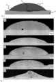
- Figure 8a shows a top view of a part surface of a contact material of an electric switch, bonded using the alloy of example 2.
- the white square corresponds to the contact surface and thereby also to the joint area.
- Figure 8b shows an image of a joint area of the electric switch braze joint of the electric switch of Figure 8a .
- the Figure 8b shows the measurement of the bonded area obtained by ultrasonic testing.
- the black portions indicate the bonded area;
- the white spots indicate defects (here: pores) within the braze joint.
- the Figure 8b reveals about 95% bonded area, which is an indication of an excellent bond.
Landscapes
- Engineering & Computer Science (AREA)
- Mechanical Engineering (AREA)
- Chemical & Material Sciences (AREA)
- Materials Engineering (AREA)
- Metallurgy (AREA)
- Organic Chemistry (AREA)
- Contacts (AREA)
Claims (20)
- Verwendung einer Legierung als Hartlötlegierung für eine Elektrischer-Schalter-Hartlötverbindung,
wobei die Legierungszusammensetzung aus Folgendem besteht:wenigstens einem Element ausgewählt aus einer der nachstehend aufgelisteten Gruppe I und Gruppe II,wobei der Rest Ag, optional wenigstens eines von Cu und Zn, und Verunreinigungen ist;Gruppe I: Cd, Mn, Ni, P, Sb, Si, Sn, Ti und Oxide davon in einer Gesamtmenge von 0,5 bis 45,0 Gew.-%; undGruppe II: Bi, Mo, Te, W und Oxide davon, Oxide von Cu und Zn, in einer Gesamtmenge von 0,1 bis 15,0 Gew.-%. - Verwendung einer Legierung gemäß Anspruch 1, wobei der Rest Ag und Cu, gegebenenfalls Zn, und Verunreinigungen ist.
- Verwendung einer Legierung gemäß Anspruch 1 oder 2, wobei
Gruppe I: Cd, Mn, Ni, P, Sb, Si, Sn, Ti und Oxide davon in einer Gesamtmenge von bis zu 15,0 Gew.-%. - Verwendung einer Legierung gemäß einem der vorstehenden Ansprüche, wobeider Rest Cu-Ag, gegebenenfalls Zn, und Verunreinigungen ist;
unddas Element ausgewählt aus Gruppe I wenigstens P einschließt. - Verwendung einer Legierung gemäß Anspruch 4, wobei Gruppe II: Bi2O3, CuO, MoO3, TeO2, WO3 und ZnO in einer Gesamtmenge von 0,1 bis 15,0 Gew.-%.
- Verwendung einer Legierung gemäß Anspruch 1, wobei die Solidustemperatur wenigstens 600 °C beträgt und eine Liquidustemperatur weniger als 950 °C beträgt.
- Verwendung einer Legierung gemäß Anspruch 1, wobei die Hartlötlegierung ohne Flussmittel verwendet werden kann.
- Verwendung einer Legierung gemäß einem der vorstehenden Ansprüche, wobei
Gruppe I aus Cd, Mn, Ni, P, Sb, Si, Sn, Ti und Oxiden davon in einer Gesamtmenge von 5,0 bis 20,0 Gew.-% besteht. - Verwendung einer Legierung gemäß einem der vorstehenden Ansprüche, wobei
Gruppe II aus Bi, Mo, Te, W und Oxiden davon, Oxiden von Cu und Zn, in einer Gesamtmenge von 0,5 bis 8,0 Gew.-% besteht. - Verwendung einer Legierung gemäß einem der vorstehenden Ansprüche, wobei
Gruppe II aus Bi, Mo, Te, W und Oxiden davon, Oxiden von Cu und Zn, in einer Gesamtmenge von 0,5 bis 8,0 Gew.-% besteht. - Verwendung einer Legierung gemäß einem der vorstehenden Ansprüche, wobei
die Gesamtmenge des wenigstens einen von Cu, Ag und Zn 20,0 bis 80,0 Gew.-% beträgt. - Verwendung einer Legierung gemäß einem der vorstehenden Ansprüche, wobei
die Menge von Zn in dem Rest 5,0 bis 40,0 Gew.-% beträgt. - Verwendung einer Legierung gemäß einem der vorstehenden Ansprüche, wobeidie Hartlötverbindung zwischen einem Ag-Metalloxid-Kontaktmaterial und einem Trägermaterial gebildet wird, wobei das Trägermaterial wenigstens eines von Al, einer Legierung auf Al-Basis, Cu, einer Legierung auf Cu-Basis, einer Legierung auf Fe-Basis und Stahl gebildet wird, und wobeidas Ag-Metalloxid-Kontaktmaterial wenigstens eines der folgenden umfasst: Ag-CdO, Ag-SnO2 und Ag-ZnO.
- Elektrischer-Schalter-Hartlötverbindung, umfassend:ein Ag-Metalloxid-Kontaktmaterial,ein Trägermaterial undeine hartgelötete Zwischenschicht zwischen dem Ag-Metalloxid-Kontaktmaterial und dem Trägermaterial,wobei die Elektrischer-Schalter-Hartlötverbindung durch Hartlöten mit einer Legierung als Hartlötlegierung gebildet wird, die eine Zusammensetzung aufweist, die besteht aus:wenigstens einem Element ausgewählt aus einer der nachstehend aufgelisteten Gruppe I und Gruppe II,wobei der Rest Ag, Verunreinigungen und wenigstens eines von Cu und Zn ist;Gruppe I: Cd, Mn, Ni, P, Sb, Si, Sn, Ti und Oxide davon in einer Gesamtmenge von 0,5 bis 45,0 Gew.-%; undGruppe II: Bi, Mo, Te, W und Oxide davon, Oxide von Cu und Zn, in einer Gesamtmenge von 0,1 bis 15,0 Gew.-%.
- Elektrischer-Schalter-Hartlötverbindung gemäß Anspruch 14, wobei
wenigstens eines von a) und b) erfüllt ist:a) das Ag-Metalloxid-Kontaktmaterial umfasst wenigstens eines der folgenden: Ag-CdO, Ag-SnO2 und Ag-ZnO; undb) das Trägermaterial umfasst wenigstens eines der folgenden: Al, Legierung auf Al-Basis, Cu, Legierung auf Cu-Basis, Legierung auf Fe-Basis und Stahl. - Elektrischer Schalter,
mit der Hartlötverbindung gemäß Anspruch 14 oder 15. - Verfahren zur Herstellung einer Elektrischer-Schalter-Hartlötverbindung, umfassendBereitstellen eines Ag-Metalloxid-Kontaktmaterials, Bereitstellen eines Trägermaterials,Bereitstellen einer Legierung zwischen dem Ag-Metalloxid-Kontaktmaterial und dem Trägermaterial, Verbinden des Ag-Metalloxid-Kontaktmaterials und des Trägermaterials durch Hartlöten mit der Legierung als Hartlötverbindung, wobeidie Legierungszusammensetzung besteht aus:wenigstens einem Element ausgewählt aus einer der nachstehend aufgelisteten Gruppe I und Gruppe II,wobei der Rest Ag, wenigstens eines von Cu und Zn, und Verunreinigungen ist;Gruppe I: Cd, Mn, Ni, P, Sb, Si, Sn, Ti und Oxide davon in einer Gesamtmenge von 0,5 bis 45,0 Gew.-%; undGruppe II: Bi, Mo, Te, W und Oxide davon, Oxide von Cu und Zn, in einer Gesamtmenge von 0,1 bis 15,0 Gew.-%.
- Verfahren zur Herstellung einer Elektrischer-Schalter-Hartlötverbindung gemäß Anspruch 17, wobei wenigstens eines von a) und b) erfüllt ist:a) das Ag-Metalloxid-Kontaktmaterial umfasst wenigstens eines der folgenden: Ag-CdO, Ag-SnO2 und Ag-ZnO; undb) das Trägermaterial umfasst wenigstens eines der folgenden: Al, Legierung auf Al-Basis, Cu, Legierung auf Cu-Basis, Legierung auf Fe-Basis und Stahl.
- Verfahren zur Herstellung einer Elektrischer-Schalter-Hartlötverbindung gemäß Anspruch 17 oder 18, wobei
das Hartlöten durch Induktionslöten, Widerstandslöten, Flammlöten oder Ofenlöten durchgeführt wird. - Verfahren zur Herstellung einer Elektrischer-Schalter-Hartlötverbindung gemäß einem der Ansprüche 17 bis 19, wobei die Hartlötlegierung gemäß einem der Ansprüche 1 bis 13 verwendet wird.
Applications Claiming Priority (2)
| Application Number | Priority Date | Filing Date | Title |
|---|---|---|---|
| EP16178564 | 2016-07-08 | ||
| PCT/EP2017/066928 WO2018007520A1 (en) | 2016-07-08 | 2017-07-06 | Use of an alloy as a brazing alloy for an electric switch braze joint, an electric switch braze joint, an electric switch and a method of producing an electric switch braze joint |
Publications (2)
| Publication Number | Publication Date |
|---|---|
| EP3481576A1 EP3481576A1 (de) | 2019-05-15 |
| EP3481576B1 true EP3481576B1 (de) | 2024-09-04 |
Family
ID=56372828
Family Applications (1)
| Application Number | Title | Priority Date | Filing Date |
|---|---|---|---|
| EP17735156.6A Active EP3481576B1 (de) | 2016-07-08 | 2017-07-06 | Verwendung einer legierung als hartlötlegierung für eine elektrische schalterlötverbindung, elektrische schalterlötverbindung, elektrischer schalter und verfahren zur herstellung einer elektrischen schalterlötverbindung |
Country Status (4)
| Country | Link |
|---|---|
| US (1) | US11052492B2 (de) |
| EP (1) | EP3481576B1 (de) |
| CN (1) | CN109414777B (de) |
| WO (1) | WO2018007520A1 (de) |
Families Citing this family (2)
| Publication number | Priority date | Publication date | Assignee | Title |
|---|---|---|---|---|
| CN108465975B (zh) * | 2018-03-22 | 2020-08-25 | 哈尔滨工业大学 | 一种钇铁石榴石铁氧体高温空气连接钎料的连接方法 |
| CN115815726B (zh) * | 2022-12-02 | 2023-09-22 | 哈尔滨工业大学 | 一种用Ag基钎料在空气下连接YSZ陶瓷与Crofer22H不锈钢的方法 |
Citations (3)
| Publication number | Priority date | Publication date | Assignee | Title |
|---|---|---|---|---|
| SU407691A1 (ru) * | 1972-04-07 | 1973-12-10 | О п и с а н изобретения407691 | |
| DE3011821A1 (de) * | 1980-03-27 | 1981-10-01 | Brown, Boveri & Cie Ag, 6800 Mannheim | Verfahren zum aufloeten zweier metallteile |
| JP2003055058A (ja) * | 2001-08-23 | 2003-02-26 | Denki Kagaku Kogyo Kk | セラミック体と銅板の接合方法 |
Family Cites Families (14)
| Publication number | Priority date | Publication date | Assignee | Title |
|---|---|---|---|---|
| DE1187333B (de) * | 1958-11-05 | 1965-02-18 | Siemens Ag | Elektrischer Kontakt mit grosser Schweisssicherheit, hoher Abbrandfestigkeit und guter Haftfestigkeit der Kontaktschicht auf dem Kontakttraeger |
| US4009027A (en) * | 1974-11-21 | 1977-02-22 | Jury Vladimirovich Naidich | Alloy for metallization and brazing of abrasive materials |
| FR2298609A1 (fr) * | 1975-01-22 | 1976-08-20 | Inst Materialovedeni | Alliage pour la metallisation et le brasage des materiaux abrasifs |
| US4409181A (en) * | 1981-08-24 | 1983-10-11 | Gte Products Corporation | Brazing compositions |
| JPS59232693A (ja) | 1983-06-17 | 1984-12-27 | Ngk Spark Plug Co Ltd | セラミツクと金属等との接合用クラツドろう材及びこれを用いたセラミツクと金属等との複合体 |
| JPS6313691A (ja) * | 1986-07-03 | 1988-01-20 | Ishifuku Kinzoku Kogyo Kk | 銀ろう材 |
| CN1008151B (zh) * | 1987-06-08 | 1990-05-30 | 津市市电工合金材料研究所 | 带预制钎料层电触头的制造方法 |
| EP0331500B1 (de) * | 1988-03-04 | 1993-01-07 | Kabushiki Kaisha Toshiba | Hartlötpaste zum Verbinden von Metalle und keramische Materialien |
| DE4118217A1 (de) * | 1990-07-04 | 1992-01-23 | Degussa | Lotlegierung |
| TW516984B (en) * | 1999-12-28 | 2003-01-11 | Toshiba Corp | Solder material, device using the same and manufacturing process thereof |
| DE102009059686A1 (de) * | 2009-12-19 | 2011-06-22 | Umicore AG & Co. KG, 63457 | Legierung |
| JP5645307B2 (ja) * | 2010-12-09 | 2014-12-24 | 日本発條株式会社 | 大気接合用ろう材、接合体、および、集電材料 |
| US8783544B2 (en) * | 2012-03-20 | 2014-07-22 | Joseph W. Harris | Brazing alloys and methods of brazing |
| CN106233409B (zh) * | 2014-04-16 | 2018-10-19 | Abb瑞士股份有限公司 | 用于开关应用的电触头顶端和电开关装置 |
-
2017
- 2017-07-06 CN CN201780042238.2A patent/CN109414777B/zh active Active
- 2017-07-06 WO PCT/EP2017/066928 patent/WO2018007520A1/en not_active Ceased
- 2017-07-06 EP EP17735156.6A patent/EP3481576B1/de active Active
-
2019
- 2019-01-08 US US16/242,450 patent/US11052492B2/en active Active
Patent Citations (3)
| Publication number | Priority date | Publication date | Assignee | Title |
|---|---|---|---|---|
| SU407691A1 (ru) * | 1972-04-07 | 1973-12-10 | О п и с а н изобретения407691 | |
| DE3011821A1 (de) * | 1980-03-27 | 1981-10-01 | Brown, Boveri & Cie Ag, 6800 Mannheim | Verfahren zum aufloeten zweier metallteile |
| JP2003055058A (ja) * | 2001-08-23 | 2003-02-26 | Denki Kagaku Kogyo Kk | セラミック体と銅板の接合方法 |
Also Published As
| Publication number | Publication date |
|---|---|
| US20190134760A1 (en) | 2019-05-09 |
| CN109414777A (zh) | 2019-03-01 |
| US11052492B2 (en) | 2021-07-06 |
| EP3481576A1 (de) | 2019-05-15 |
| CN109414777B (zh) | 2022-04-01 |
| WO2018007520A1 (en) | 2018-01-11 |
Similar Documents
| Publication | Publication Date | Title |
|---|---|---|
| KR100412765B1 (ko) | 납땜재, 그 납땜재를 사용한 디바이스 및 그 납땜재를 사용한 디바이스의 제조방법 | |
| KR101285958B1 (ko) | 땜납 합금 및 반도체 장치 | |
| KR102207301B1 (ko) | 고신뢰성의 무연 납땜 합금 | |
| KR102204246B1 (ko) | 땜납 합금 | |
| CN108971793B (zh) | 一种低温无铅焊料 | |
| CN106216872A (zh) | 一种SnBiSb系低温无铅焊料及其制备方法 | |
| US6299835B1 (en) | Cadmium-free silver alloy as low-melting brazing filler material | |
| WO2021124923A1 (ja) | 銅/セラミックス接合体、及び、絶縁回路基板 | |
| JP3736819B2 (ja) | 無鉛はんだ合金 | |
| EP3481576B1 (de) | Verwendung einer legierung als hartlötlegierung für eine elektrische schalterlötverbindung, elektrische schalterlötverbindung, elektrischer schalter und verfahren zur herstellung einer elektrischen schalterlötverbindung | |
| US20110244252A1 (en) | Solder alloy | |
| JP2021165227A (ja) | 銅/セラミックス接合体、及び、絶縁回路基板 | |
| EP3369520B1 (de) | Lötlegierung zur verhinderung von eisenerosion, harzflussmittelgefülltes lot, drahtlot, harzflussmittelgefülltes drahtlot, flussmittelbeschichtetes lot, lötverbindung und lötverfahren | |
| US3078562A (en) | Method for attaching silver-cadmium oxide bodies to a supporting member | |
| CN100464931C (zh) | 高强度高韧性含镍SnAgCuRE无铅钎料及制备方法 | |
| CN114393309B (zh) | 激光与电弧复合制备钛-钢梯度结构用焊接材料及方法 | |
| JP2021098641A (ja) | 銅/セラミックス接合体、及び、絶縁回路基板 | |
| JP6887183B1 (ja) | はんだ合金および成形はんだ | |
| EP4074678B1 (de) | Kupfer-/keramikanordnung und isolierte leiterplatte | |
| CN1255564C (zh) | 用作电器开关触头的铜基金属陶瓷材料 | |
| CN117038368A (zh) | 一种钨铜复合触点的制备方法 | |
| JP5722915B2 (ja) | 電気接点材料およびその製造方法 | |
| CN120516262A (zh) | 一种Ag-Al-Cu-In-Sm-Ti多主元共晶钎料及其制备方法和应用 | |
| Mo et al. | Resistance Microwelding of Au/Ni-Plated Phosphor Bronze Sheet to Insulated Cu Wire | |
| JPH02179368A (ja) | Ag―酸化物系複合接点材料およびその製造方法 |
Legal Events
| Date | Code | Title | Description |
|---|---|---|---|
| STAA | Information on the status of an ep patent application or granted ep patent |
Free format text: STATUS: UNKNOWN |
|
| STAA | Information on the status of an ep patent application or granted ep patent |
Free format text: STATUS: THE INTERNATIONAL PUBLICATION HAS BEEN MADE |
|
| PUAI | Public reference made under article 153(3) epc to a published international application that has entered the european phase |
Free format text: ORIGINAL CODE: 0009012 |
|
| STAA | Information on the status of an ep patent application or granted ep patent |
Free format text: STATUS: REQUEST FOR EXAMINATION WAS MADE |
|
| 17P | Request for examination filed |
Effective date: 20190208 |
|
| AK | Designated contracting states |
Kind code of ref document: A1 Designated state(s): AL AT BE BG CH CY CZ DE DK EE ES FI FR GB GR HR HU IE IS IT LI LT LU LV MC MK MT NL NO PL PT RO RS SE SI SK SM TR |
|
| AX | Request for extension of the european patent |
Extension state: BA ME |
|
| DAV | Request for validation of the european patent (deleted) | ||
| DAX | Request for extension of the european patent (deleted) | ||
| STAA | Information on the status of an ep patent application or granted ep patent |
Free format text: STATUS: EXAMINATION IS IN PROGRESS |
|
| 17Q | First examination report despatched |
Effective date: 20210812 |
|
| GRAP | Despatch of communication of intention to grant a patent |
Free format text: ORIGINAL CODE: EPIDOSNIGR1 |
|
| STAA | Information on the status of an ep patent application or granted ep patent |
Free format text: STATUS: GRANT OF PATENT IS INTENDED |
|
| RIC1 | Information provided on ipc code assigned before grant |
Ipc: C22C 30/06 20060101ALI20240129BHEP Ipc: C22C 30/02 20060101ALI20240129BHEP Ipc: C22C 9/00 20060101ALI20240129BHEP Ipc: C22C 5/06 20060101ALI20240129BHEP Ipc: B32B 15/01 20060101ALI20240129BHEP Ipc: B32B 15/00 20060101ALI20240129BHEP Ipc: B23K 35/02 20060101ALI20240129BHEP Ipc: B23K 35/30 20060101ALI20240129BHEP Ipc: B23K 35/28 20060101ALI20240129BHEP Ipc: B23K 35/26 20060101ALI20240129BHEP Ipc: B23K 1/00 20060101AFI20240129BHEP |
|
| INTG | Intention to grant announced |
Effective date: 20240216 |
|
| GRAS | Grant fee paid |
Free format text: ORIGINAL CODE: EPIDOSNIGR3 |
|
| GRAA | (expected) grant |
Free format text: ORIGINAL CODE: 0009210 |
|
| STAA | Information on the status of an ep patent application or granted ep patent |
Free format text: STATUS: THE PATENT HAS BEEN GRANTED |
|
| AK | Designated contracting states |
Kind code of ref document: B1 Designated state(s): AL AT BE BG CH CY CZ DE DK EE ES FI FR GB GR HR HU IE IS IT LI LT LU LV MC MK MT NL NO PL PT RO RS SE SI SK SM TR |
|
| REG | Reference to a national code |
Ref country code: GB Ref legal event code: FG4D |
|
| REG | Reference to a national code |
Ref country code: CH Ref legal event code: PK Free format text: BERICHTIGUNGEN Ref country code: CH Ref legal event code: EP |
|
| RAP4 | Party data changed (patent owner data changed or rights of a patent transferred) |
Owner name: ABB SCHWEIZ AG |
|
| REG | Reference to a national code |
Ref country code: IE Ref legal event code: FG4D |
|
| REG | Reference to a national code |
Ref country code: DE Ref legal event code: R096 Ref document number: 602017084624 Country of ref document: DE |
|
| REG | Reference to a national code |
Ref country code: CH Ref legal event code: PK Free format text: BERICHTIGUNGEN |
|
| RIN2 | Information on inventor provided after grant (corrected) |
Inventor name: JOHANSSON, GUNNAR Inventor name: SCHMOELZER, THOMAS Inventor name: BOEHM, MORITZ |
|
| RIN2 | Information on inventor provided after grant (corrected) |
Inventor name: JOHANSSON, GUNNAR Inventor name: SCHMOELZER, THOMAS Inventor name: BOEHM, MORITZ |
|
| RIN2 | Information on inventor provided after grant (corrected) |
Inventor name: JOHANSSON, GUNNAR Inventor name: SCHMOELZER, THOMAS Inventor name: BOEHM, MORITZ |
|
| REG | Reference to a national code |
Ref country code: LT Ref legal event code: MG9D |
|
| REG | Reference to a national code |
Ref country code: NL Ref legal event code: MP Effective date: 20240904 |
|
| PG25 | Lapsed in a contracting state [announced via postgrant information from national office to epo] |
Ref country code: NO Free format text: LAPSE BECAUSE OF FAILURE TO SUBMIT A TRANSLATION OF THE DESCRIPTION OR TO PAY THE FEE WITHIN THE PRESCRIBED TIME-LIMIT Effective date: 20241204 |
|
| PG25 | Lapsed in a contracting state [announced via postgrant information from national office to epo] |
Ref country code: GR Free format text: LAPSE BECAUSE OF FAILURE TO SUBMIT A TRANSLATION OF THE DESCRIPTION OR TO PAY THE FEE WITHIN THE PRESCRIBED TIME-LIMIT Effective date: 20241205 Ref country code: FI Free format text: LAPSE BECAUSE OF FAILURE TO SUBMIT A TRANSLATION OF THE DESCRIPTION OR TO PAY THE FEE WITHIN THE PRESCRIBED TIME-LIMIT Effective date: 20240904 Ref country code: PL Free format text: LAPSE BECAUSE OF FAILURE TO SUBMIT A TRANSLATION OF THE DESCRIPTION OR TO PAY THE FEE WITHIN THE PRESCRIBED TIME-LIMIT Effective date: 20240904 |
|
| PG25 | Lapsed in a contracting state [announced via postgrant information from national office to epo] |
Ref country code: BG Free format text: LAPSE BECAUSE OF FAILURE TO SUBMIT A TRANSLATION OF THE DESCRIPTION OR TO PAY THE FEE WITHIN THE PRESCRIBED TIME-LIMIT Effective date: 20240904 |
|
| PG25 | Lapsed in a contracting state [announced via postgrant information from national office to epo] |
Ref country code: LV Free format text: LAPSE BECAUSE OF FAILURE TO SUBMIT A TRANSLATION OF THE DESCRIPTION OR TO PAY THE FEE WITHIN THE PRESCRIBED TIME-LIMIT Effective date: 20240904 |
|
| PG25 | Lapsed in a contracting state [announced via postgrant information from national office to epo] |
Ref country code: HR Free format text: LAPSE BECAUSE OF FAILURE TO SUBMIT A TRANSLATION OF THE DESCRIPTION OR TO PAY THE FEE WITHIN THE PRESCRIBED TIME-LIMIT Effective date: 20240904 |
|
| PG25 | Lapsed in a contracting state [announced via postgrant information from national office to epo] |
Ref country code: ES Free format text: LAPSE BECAUSE OF FAILURE TO SUBMIT A TRANSLATION OF THE DESCRIPTION OR TO PAY THE FEE WITHIN THE PRESCRIBED TIME-LIMIT Effective date: 20240904 Ref country code: RS Free format text: LAPSE BECAUSE OF FAILURE TO SUBMIT A TRANSLATION OF THE DESCRIPTION OR TO PAY THE FEE WITHIN THE PRESCRIBED TIME-LIMIT Effective date: 20241204 |
|
| PG25 | Lapsed in a contracting state [announced via postgrant information from national office to epo] |
Ref country code: RS Free format text: LAPSE BECAUSE OF FAILURE TO SUBMIT A TRANSLATION OF THE DESCRIPTION OR TO PAY THE FEE WITHIN THE PRESCRIBED TIME-LIMIT Effective date: 20241204 Ref country code: PL Free format text: LAPSE BECAUSE OF FAILURE TO SUBMIT A TRANSLATION OF THE DESCRIPTION OR TO PAY THE FEE WITHIN THE PRESCRIBED TIME-LIMIT Effective date: 20240904 Ref country code: NO Free format text: LAPSE BECAUSE OF FAILURE TO SUBMIT A TRANSLATION OF THE DESCRIPTION OR TO PAY THE FEE WITHIN THE PRESCRIBED TIME-LIMIT Effective date: 20241204 Ref country code: LV Free format text: LAPSE BECAUSE OF FAILURE TO SUBMIT A TRANSLATION OF THE DESCRIPTION OR TO PAY THE FEE WITHIN THE PRESCRIBED TIME-LIMIT Effective date: 20240904 Ref country code: HR Free format text: LAPSE BECAUSE OF FAILURE TO SUBMIT A TRANSLATION OF THE DESCRIPTION OR TO PAY THE FEE WITHIN THE PRESCRIBED TIME-LIMIT Effective date: 20240904 Ref country code: GR Free format text: LAPSE BECAUSE OF FAILURE TO SUBMIT A TRANSLATION OF THE DESCRIPTION OR TO PAY THE FEE WITHIN THE PRESCRIBED TIME-LIMIT Effective date: 20241205 Ref country code: FI Free format text: LAPSE BECAUSE OF FAILURE TO SUBMIT A TRANSLATION OF THE DESCRIPTION OR TO PAY THE FEE WITHIN THE PRESCRIBED TIME-LIMIT Effective date: 20240904 Ref country code: ES Free format text: LAPSE BECAUSE OF FAILURE TO SUBMIT A TRANSLATION OF THE DESCRIPTION OR TO PAY THE FEE WITHIN THE PRESCRIBED TIME-LIMIT Effective date: 20240904 Ref country code: BG Free format text: LAPSE BECAUSE OF FAILURE TO SUBMIT A TRANSLATION OF THE DESCRIPTION OR TO PAY THE FEE WITHIN THE PRESCRIBED TIME-LIMIT Effective date: 20240904 |
|
| REG | Reference to a national code |
Ref country code: AT Ref legal event code: MK05 Ref document number: 1719841 Country of ref document: AT Kind code of ref document: T Effective date: 20240904 |
|
| PG25 | Lapsed in a contracting state [announced via postgrant information from national office to epo] |
Ref country code: NL Free format text: LAPSE BECAUSE OF FAILURE TO SUBMIT A TRANSLATION OF THE DESCRIPTION OR TO PAY THE FEE WITHIN THE PRESCRIBED TIME-LIMIT Effective date: 20240904 |
|
| PG25 | Lapsed in a contracting state [announced via postgrant information from national office to epo] |
Ref country code: PT Free format text: LAPSE BECAUSE OF FAILURE TO SUBMIT A TRANSLATION OF THE DESCRIPTION OR TO PAY THE FEE WITHIN THE PRESCRIBED TIME-LIMIT Effective date: 20250106 Ref country code: IS Free format text: LAPSE BECAUSE OF FAILURE TO SUBMIT A TRANSLATION OF THE DESCRIPTION OR TO PAY THE FEE WITHIN THE PRESCRIBED TIME-LIMIT Effective date: 20250104 |
|
| PG25 | Lapsed in a contracting state [announced via postgrant information from national office to epo] |
Ref country code: RO Free format text: LAPSE BECAUSE OF FAILURE TO SUBMIT A TRANSLATION OF THE DESCRIPTION OR TO PAY THE FEE WITHIN THE PRESCRIBED TIME-LIMIT Effective date: 20240904 Ref country code: SM Free format text: LAPSE BECAUSE OF FAILURE TO SUBMIT A TRANSLATION OF THE DESCRIPTION OR TO PAY THE FEE WITHIN THE PRESCRIBED TIME-LIMIT Effective date: 20240904 |
|
| PG25 | Lapsed in a contracting state [announced via postgrant information from national office to epo] |
Ref country code: EE Free format text: LAPSE BECAUSE OF FAILURE TO SUBMIT A TRANSLATION OF THE DESCRIPTION OR TO PAY THE FEE WITHIN THE PRESCRIBED TIME-LIMIT Effective date: 20240904 Ref country code: AT Free format text: LAPSE BECAUSE OF FAILURE TO SUBMIT A TRANSLATION OF THE DESCRIPTION OR TO PAY THE FEE WITHIN THE PRESCRIBED TIME-LIMIT Effective date: 20240904 |
|
| PG25 | Lapsed in a contracting state [announced via postgrant information from national office to epo] |
Ref country code: CZ Free format text: LAPSE BECAUSE OF FAILURE TO SUBMIT A TRANSLATION OF THE DESCRIPTION OR TO PAY THE FEE WITHIN THE PRESCRIBED TIME-LIMIT Effective date: 20240904 |
|
| PG25 | Lapsed in a contracting state [announced via postgrant information from national office to epo] |
Ref country code: IT Free format text: LAPSE BECAUSE OF FAILURE TO SUBMIT A TRANSLATION OF THE DESCRIPTION OR TO PAY THE FEE WITHIN THE PRESCRIBED TIME-LIMIT Effective date: 20240904 Ref country code: SK Free format text: LAPSE BECAUSE OF FAILURE TO SUBMIT A TRANSLATION OF THE DESCRIPTION OR TO PAY THE FEE WITHIN THE PRESCRIBED TIME-LIMIT Effective date: 20240904 |
|
| REG | Reference to a national code |
Ref country code: DE Ref legal event code: R097 Ref document number: 602017084624 Country of ref document: DE |
|
| PG25 | Lapsed in a contracting state [announced via postgrant information from national office to epo] |
Ref country code: DK Free format text: LAPSE BECAUSE OF FAILURE TO SUBMIT A TRANSLATION OF THE DESCRIPTION OR TO PAY THE FEE WITHIN THE PRESCRIBED TIME-LIMIT Effective date: 20240904 |
|
| PLBE | No opposition filed within time limit |
Free format text: ORIGINAL CODE: 0009261 |
|
| STAA | Information on the status of an ep patent application or granted ep patent |
Free format text: STATUS: NO OPPOSITION FILED WITHIN TIME LIMIT |
|
| 26N | No opposition filed |
Effective date: 20250605 |
|
| PG25 | Lapsed in a contracting state [announced via postgrant information from national office to epo] |
Ref country code: SE Free format text: LAPSE BECAUSE OF FAILURE TO SUBMIT A TRANSLATION OF THE DESCRIPTION OR TO PAY THE FEE WITHIN THE PRESCRIBED TIME-LIMIT Effective date: 20240904 |
|
| PGFP | Annual fee paid to national office [announced via postgrant information from national office to epo] |
Ref country code: DE Payment date: 20250722 Year of fee payment: 9 |
|
| PGFP | Annual fee paid to national office [announced via postgrant information from national office to epo] |
Ref country code: FR Payment date: 20250725 Year of fee payment: 9 |